


Compliance Test
System
User Manual
CTS 3.0
Contact Information
Telephone: 800 733 5427 (toll free in North America) 858 450 0085 (direct)
Fax: 858 458 0267 Email:
Domestic Sales: domorders.sd@ametek.com International Sales: intlorders.sd@ametek.com Customer Service: service.ppd@ametek.com Web: www.programmablepower.com
March 2011 |
Document No. 5004-984 Rev. R |


About AMETEK
AMETEK Programmable Power, Inc., a Division of AMETEK, Inc., is a global leader in the design and manufacture of precision, programmable power supplies for R&D, test and measurement, process control, power bus simulation and power conditioning applications across diverse industrial segments. From bench top supplies to rack-mounted industrial power subsystems, AMETEK Programmable Power is the proud manufacturer of Elgar, Sorensen, California Instruments and Power Ten brand power supplies.
AMETEK, Inc. is a leading global manufacturer of electronic instruments and electromechanical devices with annualized sales of $2.5 billion. The Company has over 11,000 colleagues working at more than 80 manufacturing facilities and more than 80 sales and service centers in the United States and around the world.
Trademarks
AMETEK is a registered trademark of AMETEK, Inc.
Other trademarks, registered trademarks, and product names are the property of their respective owners and are used herein for identification purposes only.
Notice of Copyright
Compliance Test System, User Manual © 2010 AMETEK Programmable Power, Inc. All rights reserved.
Exclusion for Documentation
UNLESS SPECIFICALLY AGREED TO IN WRITING, AMETEK PROGRAMMABLE POWER, INC.
(“AMETEK”):
(a)MAKES NO WARRANTY AS TO THE ACCURACY, SUFFICIENCY OR SUITABILITY OF ANY TECHNICAL OR OTHER INFORMATION PROVIDED IN ITS MANUALS OR OTHER DOCUMENTATION.
(b)ASSUMES NO RESPONSIBILITY OR LIABILITY FOR LOSSES, DAMAGES, COSTS OR EXPENSES, WHETHER SPECIAL, DIRECT, INDIRECT, CONSEQUENTIAL OR INCIDENTAL, WHICH MIGHT ARISE OUT OF THE USE OF SUCH INFORMATION. THE USE OF ANY SUCH
INFORMATION WILL BE ENTIRELY AT THE USER’S RISK, AND
(c)REMINDS YOU THAT IF THIS MANUAL IS IN ANY LANGUAGE OTHER THAN ENGLISH, ALTHOUGH STEPS HAVE BEEN TAKEN TO MAINTAIN THE ACCURACY OF THE TRANSLATION, THE ACCURACY CANNOT BE GUARANTEED. APPROVED AMETEK CONTENT IS CONTAINED WITH THE ENGLISH LANGUAGE VERSION, WHICH IS POSTED AT WWW.PROGRAMMABLEPOWER.COM.
Date and Revision
March 2011 Revision R
Part Number
5004-984
Contact Information
Telephone: 800 733 5427 (toll free in North America) 858 450 0085 (direct)
Fax: 858 458 0267
Email: sales@programmablepower.com service@programmablepower.com
Web: www.programmablepower.com
i

This page intentionally left blank.
ii
Important Safety Instructions
Before applying power to the system, verify that your product is configured properly for your particular application.
Hazardous voltages may be present when covers are removed. Qualified personnel must use extreme caution when servicing this equipment.
Circuit boards, test points, and output voltages also may be floating above WARNING (below) chassis ground.
The equipment used contains ESD sensitive ports. When installing equipment, follow ESD Safety Procedures. Electrostatic discharges might
WARNING cause damage to the equipment.
Only qualified personnel who deal with attendant hazards in power supplies, are allowed to perform installation and servicing.
Ensure that the AC power line ground is connected properly to the Power Rack input connector or chassis. Similarly, other power ground lines including those to application and maintenance equipment must be grounded properly for both personnel and equipment safety.
Always ensure that facility AC input power is de-energized prior to connecting or disconnecting any cable.
In normal operation, the operator does not have access to hazardous voltages within the chassis. However, depending on the user’s application configuration, HIGH VOLTAGES HAZARDOUS TO HUMAN SAFETY may be normally generated on the output terminals. The customer/user must ensure that the output power lines are labeled properly as to the safety hazards and that any inadvertent contact with hazardous voltages is eliminated.
Guard against risks of electrical shock during open cover checks by not touching any portion of the electrical circuits. Even when power is off, capacitors may retain an electrical charge. Use safety glasses during open cover checks to avoid personal injury by any sudden component failure.
Neither AMETEK Programmable Power Inc., San Diego, California, USA, nor any of the subsidiary sales organizations can accept any responsibility for personnel, material or inconsequential injury, loss or damage that results from improper use of the equipment and accessories.
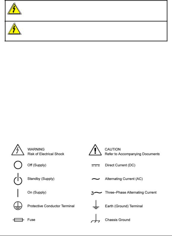
SAFETY SYMBOLS
iii

Product Family: CTS 3.0
Warranty Period: One Year
WARRANTY TERMS
AMETEK Programmable Power, Inc. (“AMETEK”), provides this written warranty covering the
Product stated above, and if the Buyer discovers and notifies AMETEK in writing of any defect in material or workmanship within the applicable warranty period stated above, then AMETEK may, at its option: repair or replace the Product; or issue a credit note for the defective Product; or provide the Buyer with replacement parts for the Product.
The Buyer will, at its expense, return the defective Product or parts thereof to AMETEK in accordance with the return procedure specified below. AMETEK will, at its expense, deliver the repaired or replaced Product or parts to the Buyer. Any warranty of AMETEK will not apply if the Buyer is in default under the Purchase Order Agreement or where the Product or any part thereof:
is damaged by misuse, accident, negligence or failure to maintain the same as specified or required by AMETEK;
is damaged by modifications, alterations or attachments thereto which are not authorized by AMETEK;
is installed or operated contrary to the instructions of AMETEK;
is opened, modified or disassembled in any way without AMETEK’s consent; or
is used in combination with items, articles or materials not authorized by AMETEK.
The Buyer may not assert any claim that the Products are not in conformity with any warranty until the Buyer has made all payments to AMETEK provided for in the Purchase Order Agreement.
PRODUCT RETURN PROCEDURE
1.Request a Return Material Authorization (RMA) number from the repair facility (must be done in the country in which it was purchased):
In the USA, contact the AMETEK Repair Department prior to the return of the product to AMETEK for repair:
Telephone: 800-733-5427, ext. 2295 or ext. 2463 (toll free North America) 858-450-0085, ext. 2295 or ext. 2463 (direct)
Outside the United States, contact the nearest Authorized Service Center (ASC). A full listing can be found either through your local distributor or our website, www.programmablepower.com, by clicking Support and going to the Service Centers tab.
2.When requesting an RMA, have the following information ready:  Model number
Serial number
Description of the problem
NOTE: Unauthorized returns will not be accepted and will be returned at the shipper’s expense.
NOTE: A returned product found upon inspection by AMETEK, to be in specification is subject to an evaluation fee and applicable freight charges.
iv

User Manual |
Compliance Test System 3.0 |
|
|
Table of Contents
1. |
Introduction ........................................................................................................................................... |
10 |
|
|
1.1 |
Manual Organization ................................................................................................................................ |
10 |
|
1.2 |
Compliance Test System Description ...................................................................................................... |
11 |
2. |
IEC Testing ........................................................................................................................................... |
16 |
|
|
2.1 |
About This Chapter .................................................................................................................................. |
16 |
|
2.2 |
The EMC Directive ................................................................................................................................... |
16 |
|
2.3 |
The IEC 61000-3-2:2000 Standard .......................................................................................................... |
17 |
|
2.4 |
The IEC 61000-3-2 Ed 2.2:2004 Standard............................................................................................... |
20 |
|
2.5 |
The IEC 61000-3-2 Ed 3.0:2005 Standard............................................................................................... |
23 |
|
2.6 |
IEC 61000-3-3 Flicker .............................................................................................................................. |
23 |
|
2.7 |
IEC 61000-4-11 Voltage Dips and Variations .......................................................................................... |
24 |
|
2.8 |
IEC 61000-4-13 Interharmonics and Harmonics Immunity Test .............................................................. |
25 |
|
2.9 |
IEC 61000-4-14 Voltage Fluctuations ...................................................................................................... |
25 |
|
2.10 |
IEC 61000-4-17 DC Ripple ...................................................................................................................... |
25 |
|
2.11 |
IEC 61000-4-27p Three Phase Voltage Unbalance ................................................................................. |
25 |
|
2.12 |
IEC 61000-4-28 Voltage Frequency Variations........................................................................................ |
26 |
|
2.13 |
IEC 61000-4-29p DC Voltage Dips, Interruptions and Variations ............................................................ |
26 |
|
2.14 |
References............................................................................................................................................... |
27 |
3. |
System Installation................................................................................................................................ |
28 |
|
|
3.1 |
About This Chapter .................................................................................................................................. |
28 |
|
3.2 |
Hardware Installation ............................................................................................................................... |
28 |
|
3.3 |
PC Requirements..................................................................................................................................... |
29 |
|
3.4 |
PACS Unit ................................................................................................................................................ |
30 |
|
3.5 |
Functional Test......................................................................................................................................... |
31 |
|
3.6 |
Front Panel Connections and Controls .................................................................................................... |
38 |
|
3.7 |
Rear Panel Connections and Controls..................................................................................................... |
42 |
|
3.8 |
Data Acquisition Card Installation - PCI Card Version ............................................................................. |
43 |
|
3.9 |
Data Acquisition Card Installation – Legacy ISA Card Version................................................................ |
53 |
|
3.10 |
CTS 3.0 Software Installation................................................................................................................... |
58 |
|
3.11 |
AC Source Control Software Installation .................................................................................................. |
59 |
|
3.12 |
Upgrading from a CTS 1.X or CTS 2.0 System........................................................................................ |
61 |
4. |
Program Menus .................................................................................................................................... |
63 |
|
|
4.1 |
About this Chapter ................................................................................................................................... |
63 |
|
4.2 |
Main Menus.............................................................................................................................................. |
63 |
|
4.3 |
File Menu ................................................................................................................................................. |
63 |
|
4.4 |
Edit Menu ................................................................................................................................................. |
64 |
|
4.5 |
View Menu ............................................................................................................................................... |
65 |
|
4.6 |
Options Menu........................................................................................................................................... |
65 |
|
4.7 |
Test Menu ................................................................................................................................................ |
66 |
5. |
Harmonics Testing................................................................................................................................ |
67 |
|
|
5.1 |
About This Chapter .................................................................................................................................. |
67 |
|
5.2 |
Test Standard Selection........................................................................................................................... |
67 |
|
5.3 |
Device Classes ........................................................................................................................................ |
67 |
|
5.4 |
Stationary or Transitory Harmonics Test.................................................................................................. |
70 |
|
5.5 |
Running a Harmonics Test....................................................................................................................... |
71 |
|
5.6 |
Additional Setup Parameters for Harmonics ............................................................................................ |
73 |
|
5.7 |
Main Harmonics Test Window Operation................................................................................................. |
75 |
|
5.8 |
Running the Harmonics Test.................................................................................................................... |
78 |
|
5.9 |
Printing Results ........................................................................................................................................ |
79 |
|
5.10 |
Harmonics Test Data Files....................................................................................................................... |
79 |
|
5.11 |
Three Phase Testing................................................................................................................................ |
79 |
|
5.12 |
Replay Mode ............................................................................................................................................ |
79 |
5

Compliance Test System 3.0 User Manual
6. |
Flicker Testing ...................................................................................................................................... |
82 |
|
|
6.1 |
About This Chapter .................................................................................................................................. |
82 |
|
6.2 |
Principle of Operation............................................................................................................................... |
82 |
|
6.3 |
Flicker Test Options ................................................................................................................................. |
82 |
|
6.4 |
Running a Flicker Test ............................................................................................................................. |
84 |
|
6.5 |
Printing Results ........................................................................................................................................ |
88 |
|
6.6 |
Flicker Replay Mode ................................................................................................................................ |
88 |
7. |
IEC 61000-4-11 Voltage Dips and Variations Immunity Testing........................................................... |
91 |
|
|
7.1 |
About This Chapter .................................................................................................................................. |
91 |
|
7.2 |
Standard Revisions and EUT Classes ..................................................................................................... |
91 |
|
7.3 |
Compliance Statement............................................................................................................................. |
91 |
|
7.4 |
Specifying Test Sequences for Dips and Variations ................................................................................ |
92 |
|
7.5 |
Test Setup................................................................................................................................................ |
95 |
|
7.6 |
Test Options............................................................................................................................................. |
96 |
|
7.7 |
Test Results ............................................................................................................................................. |
96 |
|
7.8 |
Report Format411 Test Files ................................................................................................................. |
97 |
8. |
IEC 61000-4-13 Harmonics and Interharmonics Immunity Test .......................................................... |
98 |
|
|
8.1 |
About this Chapter ................................................................................................................................... |
98 |
|
8.2 |
Tab Controls............................................................................................................................................. |
99 |
|
8.3 |
Test Setup................................................................................................................................................ |
99 |
|
8.4 |
Test Sequence ....................................................................................................................................... |
101 |
|
8.5 |
Test Results ........................................................................................................................................... |
104 |
|
8.6 |
Measurements ....................................................................................................................................... |
105 |
|
8.7 |
IEC 61000-4-13 Test Reports ................................................................................................................ |
105 |
9. |
IEC 61000-4-14 Voltage Fluctuations Immunity Testing .................................................................... |
106 |
|
|
9.1 |
About This Chapter ................................................................................................................................ |
106 |
|
9.2 |
Test Setup.............................................................................................................................................. |
107 |
|
9.3 |
Test Options........................................................................................................................................... |
107 |
|
9.4 |
Test Sequence ....................................................................................................................................... |
108 |
|
9.5 |
Test Levels............................................................................................................................................. |
109 |
|
9.6 |
Voltage Fluctuation ................................................................................................................................ |
110 |
|
9.7 |
Test Execution ....................................................................................................................................... |
111 |
|
9.8 |
Test Parameter File Creation and Limits................................................................................................ |
111 |
|
9.9 |
Test Results ........................................................................................................................................... |
111 |
|
9.10 |
Report Format414 Test Files ............................................................................................................... |
111 |
10. |
IEC 61000-4-17 DC Ripple Immunity Testing..................................................................................... |
113 |
|
|
10.1 |
About This Chapter ................................................................................................................................ |
113 |
|
10.2 |
Test Setup.............................................................................................................................................. |
114 |
|
10.3 |
Test Sequence ....................................................................................................................................... |
114 |
|
10.4 |
Waveform Display.................................................................................................................................. |
115 |
|
10.5 |
Test Results ........................................................................................................................................... |
115 |
|
10.6 |
User Observations ................................................................................................................................. |
116 |
|
10.7 |
Report Format417 Test Files ............................................................................................................... |
116 |
|
10.8 |
Saving and Loading Test Setups ........................................................................................................... |
116 |
11. |
IEC 61000-4-27p Voltage Unbalance Immunity Testing..................................................................... |
117 |
|
|
11.1 |
About This Chapter ................................................................................................................................ |
117 |
|
11.2 |
Test Setup.............................................................................................................................................. |
118 |
|
11.3 |
Equipment Classifications ...................................................................................................................... |
118 |
|
11.4 |
Test Levels............................................................................................................................................. |
120 |
|
11.5 |
Waveform Display Tab........................................................................................................................... |
120 |
|
11.6 |
Operator Observations Tab.................................................................................................................... |
120 |
|
11.7 |
Source Regulation.................................................................................................................................. |
121 |
|
11.8 |
Test execution........................................................................................................................................ |
121 |
|
11.9 |
Test Implementation and Test Sequence .............................................................................................. |
121 |
|
11.10 |
Test Reports........................................................................................................................................... |
121 |
6
User Manual |
Compliance Test System 3.0 |
||
12. IEC 61000-4-28 Frequency Variations Immunity Testing ................................................................... |
|
123 |
|
12.1 |
About This Chapter ................................................................................................................................ |
|
123 |
12.2 |
Test Setup.............................................................................................................................................. |
|
124 |
12.3 |
Test Sequence ....................................................................................................................................... |
|
125 |
12.4 |
Test Levels............................................................................................................................................. |
|
126 |
12.5 |
Test Options........................................................................................................................................... |
|
126 |
12.6 |
Test Results ........................................................................................................................................... |
|
126 |
12.7 |
Test Reports........................................................................................................................................... |
|
127 |
13. IEC 61000-4-29p DC Dips and Interruptions Immunity Test (Pre-compliance).................................. |
128 |
||
13.1 |
Test Setup.............................................................................................................................................. |
|
129 |
13.2 |
Setting nominal values ........................................................................................................................... |
|
130 |
13.3 |
Test sequence........................................................................................................................................ |
|
130 |
13.4 |
Test Options........................................................................................................................................... |
|
131 |
13.5 |
Test Execution ....................................................................................................................................... |
|
131 |
13.6 |
Test Results ........................................................................................................................................... |
|
131 |
13.7 |
IEC 61000-4-29 Test Reports ................................................................................................................ |
|
132 |
13.8 |
Source Requirements ............................................................................................................................ |
|
133 |
14. Customizing IEC 61000-4 Test Parameters ....................................................................................... |
|
134 |
|
14.1 |
About This Chapter ................................................................................................................................ |
|
134 |
14.2 |
IEC 61000-4-11 Implementations .......................................................................................................... |
|
134 |
14.3 |
Sample File IEC411.411 ........................................................................................................................ |
|
136 |
14.4 |
Sample File IEC413.413 ........................................................................................................................ |
|
137 |
15. Specifications...................................................................................................................................... |
|
138 |
|
15.1 |
About This Chapter ................................................................................................................................ |
|
138 |
15.2 |
Measurement System Specifications ..................................................................................................... |
|
138 |
15.3 |
PACS Specification ................................................................................................................................ |
|
140 |
15.4 |
Environmental ........................................................................................................................................ |
|
141 |
15.5 |
Regulatory.............................................................................................................................................. |
|
141 |
15.6 |
Flicker Reference Impedance ................................................................................................................ |
|
142 |
16. Configuration Options ......................................................................................................................... |
|
144 |
|
16.1 |
About this Chapter ................................................................................................................................. |
|
144 |
16.2 |
Accessing the Calibration and Configuration Database......................................................................... |
|
144 |
17. Calibration........................................................................................................................................... |
|
147 |
|
17.1 |
About This Chapter ................................................................................................................................ |
|
147 |
17.2 |
Calibration .............................................................................................................................................. |
|
147 |
17.3 |
Install A/D Card in PC ............................................................................................................................ |
|
148 |
17.4 |
PACS-x Calibration Setup ...................................................................................................................... |
|
148 |
17.5 |
Configuration Procedure ........................................................................................................................ |
|
149 |
17.6 |
Installing New CTS 3.0 Calibration Data ................................................................................................ |
|
152 |
18. Principle Of Operation ........................................................................................................................ |
|
153 |
|
18.1 |
General .................................................................................................................................................. |
|
153 |
18.2 |
AC Power ............................................................................................................................................... |
|
153 |
18.3 |
PACS1 or PACS3 Measurement Unit .................................................................................................... |
|
153 |
18.4 |
CTS 3.0 Software ................................................................................................................................... |
|
153 |
19. Service ................................................................................................................................................ |
|
155 |
|
19.1 |
Cleaning ................................................................................................................................................. |
|
155 |
19.2 |
General .................................................................................................................................................. |
|
155 |
19.3 |
Basic Operation...................................................................................................................................... |
|
155 |
19.4 |
Advanced Troubleshooting .................................................................................................................... |
|
158 |
Index.......................................................................................................................................................... |
|
|
160 |
7

Compliance Test System 3.0 |
User Manual |
|
List of Tables |
|
|
Table 1-1: CTS AC Source Models................................................................................................. |
12 |
|
Table 2-1: IEC 61000-3-2 Class Limits ........................................................................................... |
18 |
|
Table 2-2: Harmonics Amendment 14 Test Times ......................................................................... |
19 |
|
Table 2-3: IEC 61000-3-2 Class Descriptions................................................................................. |
21 |
|
Table 2-4: Average public utility disturbances per annum in Europe .............................................. |
24 |
|
Table 3-1: PC Pentium/Athlon Processor Clock Speed Requirement ............................................ |
29 |
|
Table 3-2: Reserved PC I/O Address Locations ............................................................................. |
55 |
|
Table 5-1 |
: IEC Harmonics Setup Parameters ............................................................................... |
72 |
Table 5-2 |
: IEC Harmonics Advanced Setup Parameters .............................................................. |
74 |
Table 5-3 |
: IEC Harmonics Replay Settings ................................................................................... |
81 |
Table 6-1 |
: IEC Flicker Replay Settings .......................................................................................... |
90 |
Table 15-1 PACS Specifications ................................................................................................... |
140 |
|
Table 17-1: Required Calibration Equipment................................................................................ |
147 |
|
8

User Manual |
Compliance Test System 3.0 |
|
List of Figures |
|
|
Figure 3-1: EUT Connection distance and wire gauge. .................................................................. |
|
30 |
Figure 3-2: Functional Test Setup................................................................................................... |
|
32 |
Figure 3-3: Single-phase configuration 5001iX-CTS ...................................................................... |
|
33 |
Figure 3-4: Single-phase configuration 1251RP-CTS..................................................................... |
|
34 |
Figure 3-5: Power Connections for PACS-1 for a single-phase CTS. ............................................ |
|
35 |
Figure 3-6: Three-phase configuration 15003iX-CTS..................................................................... |
|
36 |
Figure 3-7: Power Connections for PACS-3 in a three-phase CTS. ............................................... |
|
37 |
Figure 3-8: Switch Settings for Remote Impedance Control (Factory Default) |
............................... 39 |
|
Figure 3-9: Switch Settings for Manual Impedance Control............................................................ |
|
39 |
Figure 3-10: Front and Rear Panel Views of the PACS-1 Module. ................................................. |
|
40 |
Figure 3-11: Front and Rear Panel Views of the PACS-3 Module. ................................................. |
|
41 |
Figure 3-12: Exacq Control Center Screen..................................................................................... |
|
46 |
Figure 3-13: Exacq Card Device Number ....................................................................................... |
|
47 |
Figure 3-14: Exacq Test Panel ....................................................................................................... |
|
48 |
Figure 3-15: Exacq DMM Screen.................................................................................................... |
|
49 |
Figure 3-16: Exacq Scope Test Panel ............................................................................................ |
|
50 |
Figure 3-17: NI E Series Explorer Panel ......................................................................................... |
|
51 |
Figure 3-18: Figure 3 .................................................................. |
|
51 |
Figure 3-19: Jumper and DIP switch location on the A/D Card ...................................................... |
|
53 |
Figure 3-20: A/D Card JMP 11 Settings.......................................................................................... |
|
54 |
Figure 3-21: A/D Card JMP 13 Settings.......................................................................................... |
|
54 |
Figure 3-22: A/D Card Base I/O Address DIP................................................................................. |
|
56 |
Figure 5-1: Class D Current Wave Shape Template ...................................................................... |
|
68 |
Figure 5-2: EUT Class Determination Flowchart ............................................................................ |
|
69 |
Figure 5-3: Typical Class A test setup ............................................................................................ |
|
71 |
Figure 5-4: Additonal Settings for Harmonics Test ......................................................................... |
|
73 |
Figure 5-5: Harmonics Test Window .............................................................................................. |
|
75 |
Figure 6-1: Flicker Test Window ..................................................................................................... |
|
84 |
Figure 7-1: IEC 61000-4-11 Test Window ...................................................................................... |
|
92 |
Figure 7-2: IEC 61000-4-11 Voltage Variation specificationEdition 1.0 ........................................ |
|
93 |
Figure 7-3: IEC 61000-4-11 Voltage Variation specificationEdition 2.0 ........................................ |
|
93 |
Figure 7-4: IEC 61000-4-11 Setup screen ...................................................................................... |
|
95 |
Figure 8-1: IEC 61000-4-13 Test Window ...................................................................................... |
|
98 |
Figure 8-2: IEC 61000-4-13 Flow Chart Class 1 and 2. ................................................................ |
|
101 |
Figure 8-3: IEC 61000-4-13 Flow Chart Class 3........................................................................... |
|
102 |
Figure 9-1: IEC 61000-4-14 Test Window .................................................................................... |
|
106 |
Figure 9-2: IEC 61000-4-14 Test Sequence ................................................................................. |
|
108 |
Figure 10-1: IEC 61000-4-17 Test Window .................................................................................. |
|
113 |
Figure 10-2: IEC 61000-4-17 Waveform Acquisition Window ...................................................... |
|
115 |
Figure 10-3: IEC 61000-4-17 User Observation Data Entry Window ........................................... |
|
116 |
Figure 11-1: IEC 61000-4-27 Test Window .................................................................................. |
|
117 |
Figure 12-1: IEC 61000-4-28 Test Window .................................................................................. |
|
123 |
Figure 12-2: IEC 61000-4-28 Test Sequence ............................................................................... |
|
125 |
Figure 13-1: IEC 61000-4-29 Test Window .................................................................................. |
|
128 |
Figure 17-1 : CTS 3.0 Calibration Program Main Screen ............................................................. |
|
148 |
Figure 17-2: Single Phase Calibration Setup ................................................................................ |
|
150 |
Figure 17-3: Three Phase Calibration Setup ................................................................................ |
|
151 |
Figure 19-1: Location of AC Sensor Assy. 5004-700 in PACS-x .................................................. |
|
157 |
9

Compliance Test System 3.0 |
User Manual |
|
|
1.Introduction
1.1Manual Organization
This manual describes the operation of the California Instruments Compliance Test System Software when used in conjunction with the CTS hardware. Its primary function is as a reference manual. If you have a question about a specific screen or how to perform a certain task, turn to the appropriate section of the manual. The manual is organized in accordance with the normal test procedure you would follow when testing for IEC compliance.
Some assumptions were made when producing this documentation. Specifically, it is assumed that you are familiar with the IEC 61000-3-2 and IEC 61000-3-3 standards and their requirements. Some background information on the IEC standards covered by the CTS system is included in chapter 2. This information is subject to change however as standards do change. We recommend you stay current with evolving test standards and regulations. Furthermore, it is also assumed that you are familiar with operating a personal computer under the Microsoft Windows™ environment.
The manual is organized as follows:
Chapter 1 describes the organization of the user manual and provides a brief overview of the CTS system components.
Chapter 2 provides an overview of the relevant IEC regulations and how compliance testing to these regulations is implemented in the CTS 3.0 Software.
Chapter 3 covers installation of the hardware and software components required to operate the CTS system. Proper installation of both hardware and software is essential. This chapter walks the user through the hardware setup and the software installation, process one step at a time.
Chapter 4 Overview of the program's menu structure
Chapter 5 covers IEC 61000-3-2 harmonics testing. This chapter provides step by step instructions on how to set up the correct test mode and perform the necessary steps to perform a quasi-stationary or transitory Harmonics test on the EUT.
Chapter 6 covers IEC 61000-3-3 Voltage fluctuations testing. This chapter provides step by step instructions on running a voltage fluctuation or flicker test.
Chapter 7 covers IEC 61000-4-11 Voltage Dips and Variations immunity testing.
Chapter 8 covers IEC 61000-4-13 standard Voltage Fluctuations immunity testing. [Draft version]
Chapter 9 covers IEC 61000-4-14 standard Voltage Fluctuations immunity testing.
Chapter 10 covers IEC 61000-4-17 standard DC Ripple immunity testing.
Chapter 11 covers IEC 61000-4-27p standard Voltage Unbalance immunity testing.
Chapter 12 covers IEC 61000-4-28 standard Frequency Variations immunity testing.
Chapter 13 covers IEC 61000-4-29p DC Voltage dips and Variations immunity testing.
Chapter 14 covers IEC 61000-4 customization to allow for future revisions of these standards and to accommodate different product categories.
10

User Manual |
Compliance Test System 3.0 |
|
|
Chapter 15 provides the technical specifications for the Power Analysis and Conditioning System (PACS) unit, which is a key component of the CTS system. For technical specifications on the AC source supplied with the CTS system, refer to the AC source manual provided.
Chapter 16 overview of available configuration options.
Chapter 17 overview of calibration procedures
Chapter 18 provides theory of operation information.
Chapter 19 provides service and troubleshooting procedures.
1.2Compliance Test System Description
The California Instruments Compliance Test System is a complete IEC AC power test system that covers many of the IEC regulatory test standards involving AC and/or DC powered equipment.
To ensure maximum flexibility of both the hardware and the software required to create a turn-key system, the CTS system uses a modular structure consisting of the following components:
Programmable AC power source. The AC source provides precise, isolated and low distortion AC power at the user specified frequency and voltage. The AC source also offers over current protection to avoid damaging a load that exhibits a failure. The AC source can either be a single-phase or three-phase unit. For some DC tests, iX Series based CTS systems also provide DC output.
Power Analysis and Conditioning System unit. The PACS unit creates the electrical and mechanical interface between the AC source, the Equipment Under Test (EUT) and the PC based data acquisition system. It provides the necessary signal conditioning and isolation for the acquisition system.
PC Based data acquisition system. The data acquisition system uses a fast Analog to Digital conversion card that plugs into an available card slot in the user‟s PC. The CTS 3.0 software controls all aspects of the A/D card and processes the data for IEC test purposes.
CTS 3.0 Software. The CTS 3.0 software implements the harmonics and flicker IEC tests. In addition to the CTS 3.0 Software, the California Instruments CIGUI32 (Series I iX) or CIGuiSII (Series II iX) Windows program is used to control the AC and DC source used and to implement those IEC tests that run on the AC source, specifically the IEC 61000-4 immunity tests.
The AC source output is connected to the rear of the PACS unit. For single-phase applications the user only needs to connect the EUT to the IEC/77 connector located on the front panel of the PACS unit to set up his test hardware. For three phase applications the rear terminals are used. All user interactions with the CTS system are accomplished through the CTS 3.0 and CIGUI32 or CIGuiSII software. There are virtually no front panel controls required to operate the CTS system.
11
Compliance Test System 3.0 |
User Manual |
|
|
1.2.1AC Source Models
The CTS system is supplied with different programmable AC power sources depending on the configuration. The following AC sources are supplied with each CTS system:
Table 1-1: CTS AC Source Models
|
Model |
|
|
VA Power |
|
|
AC Source |
|
|
IEC |
|
|
PACS |
|
|
|
|
|
|
|
|
|
|
|
|
||||||
|
|
|
|
|
|
|
|
|
|
|
61000-4 |
|
|
model |
|
|
|
|
|
|
|
|
|
|
|
|
|||||
|
|
|
|
|
|
|
|
|
|
|
|
|
|
|
|
|
Single Phase Systems |
|
|
|
|
|
|
|
|
|
|
|
|
|
|
|
|
|
|
|
|
|
|
|
|
|
|
|
|||
|
100-CTS |
|
AC Line |
|
|
none |
|
- |
|
|
PACS-1 |
|
|||
|
|
|
|
|
|
|
|
|
|
|
|
|
|||
|
1251RP-CTS |
|
1250 VA |
|
|
1251RP |
|
- |
|
|
PACS-1RP |
|
|||
|
|
|
|
|
|
|
|
|
|
|
|
|
|
||
|
3001iX-CTS |
|
3000 VA |
|
|
3001iX |
|
|
|
|
|
PACS-1 |
|
||
|
|
|
|
|
|
|
|
|
|
|
|
|
|
||
|
5001iX-CTS (-400) |
5000 |
VA |
|
|
5001iX (-400) |
|
|
|
|
|
PACS-1 |
|
||
|
|
|
|
|
|
|
|
|
|
|
|
|
|
||
|
10001iX-CTS (-400) |
10000 |
VA |
|
|
10001iX (-400) |
|
|
|
|
|
PACS-1-75 |
|
||
|
|
|
|
|
|
|
|
(See note below) |
|
|
|
|
|
|
|
|
|
|
|
|
|
|
|
|
|
|
|
|
|
|
|
|
Three Phase Systems |
|
|
|
|
|
|
|
|
|
|
|
|
|
|
|
|
|
|
|
|
|
|
|
|
|
|
||||
|
300-CTS-75 |
|
AC Line |
|
|
none |
|
- |
|
|
PACS-3-75 |
|
|||
|
|
|
|
|
|
|
|
|
|
|
|
|
|
||
|
15003iX-CTS (-400) |
15000 |
VA |
|
|
15003iX |
|
|
|
|
|
PACS-3 |
|
||
|
|
|
|
|
|
|
|
|
|
|
|
|
|
||
|
30003iX-CTS (-400) |
15000 |
VA |
|
|
30003iX-400 |
|
|
|
|
|
PACS-3-75 |
|
||
|
|
|
|
|
|
|
|
(See note below) |
|
|
|
|
|
|
|
|
|
|
|
|
|
|
|
|
|
|
|
|
|
|
|
If you plan to use the AC line and are using a PACS-1 or PACS-3 system, you can skip this paragraph as there is no AC source included with the system. If you are using any of the other CTS configurations, the AC source includes its own user manual. We recommend you familiarize yourself with the operation of the AC source and the included Windows Graphical User Interface (CIGUI32 or CIGuiSII) for it before you start using the CTS system.
Note: PACS-1 and PACS-3 based CTS systems are rated for a maximum current of 40 amps rms per phase. Higher current versions, PACS-1-75 and PACS-3-75, are available. Existing 10001iX-CTS and 30003iX-CTS systems may not have been shipped with these -75 model versions however. Damage to the standard PACS units can occur if higher currents are present. Care must be taken to not exceed this rating when using the system directly with the utility line or with the higher power sources. When using a 10001iX-CTS or 30003iX-CTS system, the lower voltage/higher current output range should not be used unless the AC source‟s current limit has been set to 40 amps or less or the system was supplied with the -75 version of the PACS.
12

User Manual |
Compliance Test System 3.0 |
|
|
1.2.2PACS Unit
The Power Analysis and Conditioning System provides the required electrical and mechanical interface between the AC source, the user‟s equipment under test and the data acquisition PC system. This allows all signal connections to be made easily and conveniently. The PACS can be single phase or three phase, depending on the CTS system configuration in use. Single phase PACS units may also contain the required reference impedance for making flicker measurements when a power source without programmable impedance is used. PACS units with the reference impedance built-in have a Bypass and Flicker mode that is controlled through the A/D card digital I/O from the CTS 3.0 software. The front panel controls for Bypass and Flicker mode are disabled. The mode of operation (Bypass for harmonics measurements and Flicker for flicker measurements) is indicated with a set of LED‟s.
The PACS unit has several AC power input and output connections as well as an interface connector to the PC based data acquisition system.
For higher power systems, the CTS system can be configured with the 75 A per phase versions of the PACS unit. (Standard on 30003iX-CTS system).
13
Compliance Test System 3.0 |
User Manual |
|
|
1.2.3PC Based Data Acquisition System (updated for new PCI data acquisition)
All measurements required for IEC testing are performed by the data acquisition system that resides on the user‟s PC. The measurement card needs to be installed in an available slot and the software needs to be installed. All signal connections between the PC and the PACS unit are made with a single 37-pin cable supplied with the system.
The following data acquisition cards are supported by the CTS 3.0 software:
CI400PCI |
PCI card |
NI 6032/4E. No longer provided on new system shipments but |
|
|
still supported by CTS30 software revision 3.2.X |
CI401PCI |
PCI card |
Exacq Technologies CM2110 PCI A/D card, 250 Ks/sec for |
|
|
single phase systems (P/N 250803) |
CI403PCI |
PCI card |
Exacq Technologies CM2210 PCI A/D card, 1 Ms/sec for three |
|
|
phase systems (P/N 250797) |
All CTS systems are delivered with a PCI bus A/D card. Older systems may use the –ISA or -MC cards. The CTS 3.0 software installation differs for each of these legacy A/D cards. For new installations, only the PCI card should be used however.
The data acquisition system samples all voltage and current channels at a high sampling rate and provides the data to the CTS 3.0 software for further processing. The PACS provides a single voltage input channel and three current input channels for each phase, to the PC. This allows for current range changing on the fly. There is no need for the user to select a current range as the software automatically uses the most suitable range available for the current signal.
1.2.4CTS 3.0 Software Functions
The CTS 3.0 software application supports IEC 61000-3-2 and IEC 61000-3-3 compliance testing requirements using an intuitive graphical user-interface from which you can:
Set up and run compliance-level tests. The setting up of many IEC details is facilitated through the use of embedded standards expertise.
Collect real-time test data from the CTS System.
Display and monitor real-time test results.
Save test results to disk for analysis using other programs.
Replay previously recorded test data and single step through the data frame by frame.
Print reports and graphs in MS Word™ formats.
1.2.5AC Source GUI Functions
If the CTS system in use was supplied with an AC source, it also includes an AC source control software package. This Graphical User Interface program can be used to control the AC source from the same PC using either the RS232C or IEEE-488 interface. An IEEE-488 interface is not included with the CTS system. The PC must have an available RS232C port to use the RS232C control interface to the source.
In the absence of a suitable interface, the user can operate the AC source from the front panel.
This does not affect the ability to run harmonics and flicker tests. It does however preclude the use of the IEC 61000-4 immunity tests, which are only available through the CIGUI321 or CIGuiSII AC source control program.
1 IEC 61000-4 tests are pre-compliance only on the 1251-CTS.
14

User Manual |
Compliance Test System 3.0 |
|
|
Note on Interface conflicts:
If the CIGUI32 or CIGuiSII program is set up to use the same serial or IEEE-488 port (any address) to communicate with the AC source as the CTS 3.0 software, it is not possible to have both the CTS 3.0 Software and the CIGUI32 or CIGuiSII software running at the same time. This is due to the fact that both programs would attempt to use the same interface to control the AC source. If this is the case, close one program before opening the other.
If IEEE-488 is used to control the AC source with the CIGUI32 or CIGuiSII and RS232C is selected on the CTS 3.0 or vice versa, both programs can be open at the same time but care should be taken not to control the source from both programs at the same time. This setup is not recommended however.
For best results, use either program in turn depending on the task at hand (CTS 3.0 for IEC 61000-3 and CIGUI32 or CIGuiSII for IEC 61000-4)
15
Compliance Test System 3.0 |
User Manual |
|
|
2.IEC Testing
2.1About This Chapter
This chapter provides some background information on the various IEC test standards that apply to AC powered products. It also reviews some of the test equipment requirements that are important when testing for IEC compliance. Note that this information is subject to change as IEC standards change over time. This overview is by no means comprehensive and is only provided for reference. If the reader is not familiar with IEC test requirements for AC powered products, we strongly recommend consulting information on this subject that is available through other sources. References are provided at the end of this chapter.
The standards covered in this chapter include those, which the CTS system is capable of testing, specifically:
IEC 61000-3-2 Quasi Static and Transitory Harmonics
IEC 61000-3-3 Flicker
IEC 61000-4-11 Voltage Dips and Variations (requires option -411 and EOS1 or EOS3)
IEC 61000-4-13 Interharmonics and Harmonics Immunity Test [Draft standard] (requires option -413)
IEC 61000-4-14 Voltage Fluctuations
IEC 61000-4-17 DC Ripple
IEC 61000-4-27p AC Voltage Unbalance (pre-compliance)
IEC 61000-4-28 Frequency Variations
IEC 61000-4-29p DC Voltage Dips and Variations (pre-compliance)
2.2The EMC Directive
As the world population grows and the overall energy consumption increases, industrialized nations have become increasingly concerned with the future availability of energy. Reducing energy consumption by using more energy efficient lighting and motor drive systems is one approach being taken by European, US and Japanese governments. The need of more efficient electrical systems however typically requires the use of sophisticated semi-conductor based electronic circuits that produce current harmonics. This in turn effects power quality which is an increasing problem on public utility networks. As lighting systems with electronic ballasts and equipment with switching power supplies such as computers, TV‟s, fax machines and printers proliferate, power quality deteriorates. The same is true for PWM controller motor drives. The International Electrical Committee (IEC) has released standards dealing with the low frequency public supply system. Initial standards were 555.2 (Harmonics) and 555.3 (Flicker) which have since been refined and are now available as IEC 61000-3-2 and IEC 61000-3-3 respectively. Effective January 1, 1996, most electrical devices sold within the member countries of the European Union (EU) must meet these standards as governed by the EMC directive.
16
User Manual |
Compliance Test System 3.0 |
|
|
2.2.1Why do you have to test?
In general, these IEC directives do not have the legal force of law. However, the European Union (EU) has issued Euro Norms in the context of these IEC directives that are legally binding and are enforced by the EMC Police. The relevant enforceable standards are IEC 61000-3-2 and IEC 61000-3-3, which supersede EN60555.2 and EN60555.3 respectively. These standards are also known under the IEC designator IEC 61000-3-2 and IEC 61000-3-3. Recently, the universal IEC 61000 convention has been adopted for all IEC standards.
Individual member countries have issued identical national norms, either in their native language or in English, which carry the same legal enforceability. Other countries such as Japan and the USA are in the process of adopting similar standards. Penalties for violating these norms range from hefty fines to jail time. In cases where the manufacturer is not located in the EU, his distributor or authorized agent will be held liable. Local customs agencies can stop equipment that does not meet these IEC norms at the border. Compliance testing of equipment is performed by accredited laboratories run by European government agencies assigned with enforcing these norms. Also, competing vendors have been known to submit failing test results on competitors' products to local governments to force prosecution and gain a competitive advantage in the market place.
Conformance to the EMC low voltage directive is indicated by the CE mark. Note however, that the CE mark includes MORE than just IEC 61000-3-2 and IEC 61000-3-3.
2.3The IEC 61000-3-2:2000 Standard
This standard is often referred to as Amendment 14. It is less stringent for class C and D products compared to the 1998 standard. Effective January 2001, products may be evaluated against this standard.
2.3.1Test Classes
CENELEC-A14 changes the definition of Class-D products. Per the amendment, only TV‟s, PC‟s and PC monitors are to be tested per Class-D limits. This means that many products migrate to Class-A. Note that there is no change in classification for Class-A, B, and C products, but the harmonic analysis method for products with fluctuating power is affected by A-14 for these products as well.
The limits for Class-C & D are proportional. Whereas this doesn‟t cause any difficulties for products with a constant current/power level, the situation was less clear for products with fluctuating load levels. Most test systems implemented so-called dynamic limits, with the limits constantly being adjusted per the measured power (or the fundamental current for Class-C) while others used some average power level to set the limits. The latter systems determine this average power/current using some arbitrary method, and pre-test period. Thus different test systems implement different limits for the same (fluctuating power) products, which can result in one system PASSING a product while the other REJECTS it.
A second issue for fluctuating loads is the way the existing standard (1998 edition) defines criteria for passing and failing the harmonics test. The existing standard permits the unit under test to occasionally exceed the 100 % limit, provided the harmonics never exceed 150 % of the limit. In fact, the unit under test is allowed to exceed the 100 % level for 10 % of the test time. The test time for fluctuating loads is to be at least 2.5 minutes, i.e. the harmonics can exceed the 100 % limit for 15 seconds in every 150-second (2.5 min) period. For longer test times, one can perform this test in 2.5 minutes “time blocks” but another interpretation is to just take 10 % of the overall test time. Thus, the testing method for fluctuating loads was somewhat subject to interpretation by the test equipment manufacturer.
17

Compliance Test System 3.0 |
User Manual |
|
|
Pass/Fail criteria under the new standard are as follows:
The average value for the individual harmonic currents, taken over the entire test observation period shall be less than or equal to the applicable limits.
For each harmonic order, all 1,5 s smoothed r.m.s. harmonic current values shall be less than or equal to 150% of the applicable limits.
Harmonic currents less than 0,6% of the input current measured under the test conditions, or less than 5 mA, whichever is greater, are disregarded.
For the 21st and higher odd order harmonics, the average values obtained for each individual odd harmonic over the full observation period, calculated from the 1,5 s smoothed values may exceed the applicable limits by 50% provided that the following conditions are met:
The measured partial odd harmonic current does not exceed the partial odd harmonic current, which can be calculated from the applicable limits.
All 1,5 s smoothed individual harmonic current values shall be less than or equal to 150% of the applicable limits.
2.3.2IEC 61000-3-2 Test Limits
The following table summarizes the current harmonic limits for each device class that are presently in effect. The limits are generally built into IEC test software programs such as California
Instruments‟ CTS 3.0 Test System software. If the power level of a class D device drops below 75
W (configurable - see System Administrator Manual P/N 5004-985), no harmonic current limits are applied and the result will always show a pass.
Table 2-1: IEC 61000-3-2 Class Limits
|
Harmonic no. (n) |
|
|
Class A |
|
|
Class B |
|
|
Class C |
|
|
Class D |
|
|
IEC 555-2 |
|
|
|
|
|
|
|
|
|
|
|
|
|
||||||
|
|
|
|
|
|
|
|
|
|
|
|
|
|
|
|
|
|
|
|
|
|
A RMS |
|
|
A RMS |
|
|
% of |
|
|
mA/Watt of |
|
|
A RMS |
|
|
|
|
|
|
|
|
|
|
|
fundamental |
|
|
input power |
|
|
TV Receivers |
|
|
|
|
|
|
|
|
|
|
|
RMS current |
|
|
(75 - 600 W) |
|
|
> 165 W |
|
|
|
|
|
|
|
|
|
|
|
|
|
|
|
|
|
||
|
|
|
|
|
|
|
|
|
|
|
|
||||||
2 |
|
1.080 |
|
1.620 |
|
2 |
|
- |
|
0.300 |
|
||||||
|
|
|
|
|
|
|
|
|
|
|
|
|
|||||
3 |
|
2.300 |
|
3.450 |
|
|
30 x PF |
|
3.400 |
|
0.800 |
|
|||||
|
|
|
|
|
|
|
|
|
|
|
|
||||||
4 |
|
0.430 |
|
0.645 |
|
- |
|
- |
|
0.150 |
|
||||||
|
|
|
|
|
|
|
|
|
|
|
|
||||||
5 |
|
1.140 |
|
1.710 |
|
10 |
|
1.900 |
|
0.600 |
|
||||||
|
|
|
|
|
|
|
|
|
|
|
|
||||||
6 |
|
0.300 |
|
0.450 |
|
- |
|
- |
|
- |
|
||||||
|
|
|
|
|
|
|
|
|
|
|
|
||||||
7 |
|
0.770 |
|
1.155 |
|
7 |
|
1.000 |
|
0.450 |
|
||||||
|
|
|
|
|
|
|
|
|
|
|
|
||||||
8 |
|
0.230 |
|
0.345 |
|
- |
|
- |
|
- |
|
||||||
|
|
|
|
|
|
|
|
|
|
|
|
||||||
9 |
|
0.400 |
|
0.600 |
|
5 |
|
0.500 |
|
0.300 |
|
||||||
|
|
|
|
|
|
|
|
|
|
|
|
||||||
10 |
|
0.184 |
|
0.276 |
|
- |
|
- |
|
- |
|
||||||
|
|
|
|
|
|
|
|
|
|
|
|
||||||
11 |
|
0.330 |
|
0.495 |
|
3 |
|
0.350 |
|
0.170 |
|
||||||
|
|
|
|
|
|
|
|
|
|
|
|
||||||
12 |
|
0.153 |
|
0.230 |
|
- |
|
- |
|
- |
|
||||||
|
|
|
|
|
|
|
|
|
|
|
|
||||||
13 |
|
0.210 |
|
0.315 |
|
3 |
|
0.296 |
|
0.120 |
|
||||||
|
|
|
|
|
|
|
|
|
|
|
|
|
|
|
|||
|
Even 14-40 |
|
|
1.84 / n |
|
|
2.760 / n |
|
- |
|
- |
|
- |
|
|||
|
|
|
|
|
|
|
|
|
|
|
|
|
|
|
|
|
|
|
Odd 15-39 |
|
|
2.25 / n |
|
|
3.338 / n |
|
3 |
|
|
3.850 / n |
|
|
1.500 / n |
|
|
|
|
|
|
|
|
|
|
|
|
|
|
|
|
|
|
|
|
The actual class limits for all classes have not changed with amendment 14. The power levels for Class D on which these limits are calculated however and the fundament current and power factor for class C have been changed however.
First of all, the manufacturer is required to declare the rated power (the fundamental current and Power Factor for Class-C) for the product. This “rated power” (current & PF) will be used as the
18

User Manual |
Compliance Test System 3.0 |
|
|
basis for the limit calculation of Class-D (Class-C). Thus, a “rated power” of 150 Watt for example, will yield a third harmonic limit of 150 x 3.4 = 510 mA. Similarly, a rated fundamental current of 0.4 Amp, and a rated PF of 0.98 for an electronic ballast will result in a third harmonic limit of 0.4 x 0.3 x 0.98 = 117.6 mA. Thus, the amendment requires that an automated compliance test system must allow the user to enter this rated power or rated current. Also, the test system must verify the power (fundamental current and PF) because these “rated vales” as declared by the manufacturer must be within +/- 10 % of the actual values. If not, the actually measured values are to be used for the limit calculation. The method to measure these actual power, fundamental current and PF differ from the “average method” used in existing test systems, and of course differ also from the “dynamic limit method”.
The Pass/Fail criterion is given above. The “10 % of the time over 100 % of the limits” no longer exists. The average harmonic level during the whole test must simply be below the limit, and individual values in each acquisition window (after 1.5 sec filtering) must be below 150 % of the limit. There is also an extra allowance for the higher harmonics from H 21 - H 39 .
The CTS fully supports and implements Amendment 14.
2.3.3IEC 61000-3-2:2000 Test Time
Under the new test standard, four test times (observation periods) are allowed depending on the nature of the EUT. All are aimed at ensuring repeatability of test results when tests are performed under the same conditions and on the same test system. Repeatability for this purpose is defined as results that are within 5 %. Available observation periods shown in the table below.
Table 2-2: Harmonics Amendment 14 Test Times
Type of equipment |
Observation period |
behavior |
|
|
|
Quasi-stationary |
Tobs of sufficient duration to meet the requirements for |
|
repeatability. |
|
|
Short cycles (Tcycle < 2.5 |
Tobs > 10 cycles (reference method) or Tobs of sufficient duration |
min) |
or synchronization to meet the requirements for repeatability. |
|
'Synchronization' means that the total observation period is |
|
sufficiently close to including an exact integral number of |
|
equipment cycles such that the requirements for repeatability are |
|
met. |
|
|
Random |
Tobs of sufficient duration to meet the requirements for |
|
repeatability. |
|
|
Long cyclic (Tcycle > 2.5 |
Full equipment program cycle (reference method) or a |
min) |
representative 2.5-min period considered by the manufacturer as |
|
the operating period with the highest total harmonic content. |
|
|
19

Compliance Test System 3.0 |
User Manual |
|
|
2.4The IEC 61000-3-2 Ed 2.2:2004 Standard
This section covers the 2004 standard which incorporates amendments 1 and 2 and amendment 14. This standard must be to test products since January 2004..
The purpose of enforcing the IEC 61000-3-2 standard is to limit the amount of current harmonics produced by electronic loads. Since harmonic currents caused by a load in turn produce voltage harmonics across the public utilities impedance, they affect other equipment connected to the same circuit. In fact, most public utilities exhibit voltage distortion caused by non-linear loads. Because harmonics can have serious effects on many electrical devices, efforts to set standards to limit their presence date back to the 1930‟s. This resulted in the IEC‟s Technical Committee
(TC) setting standards dealing with current harmonics as far back as 1977. These standards became the basis for IEC standards 1000-3-2 and 1000-3-3 adopted in 1993. Because of their long history, many people still refer to these standards as 555.2 and 555.3 although there are some differences between the older and newer versions and tests performed today should be done according to the new standards, not the old ones.
Another confusing issue that is rooted in history is the nature of the products that fall under these IEC norms. While the original 555 specifications focused primarily on consumer products and excluded many professional and industrial products, the new IEC 1000-3 norms expanded coverage to include all electrical products with a rated input current up to 16 A rms per phase. Presently, only products with a line input voltage of 220 V and above are included. Japan and the US are working towards similar requirements that would cover products that require 100 Volts and up. Due to the original scope of the IEC 555 norms, many manufacturers are still under the impression that their products are exempt since they are not considered consumer products. Especially manufacturers of switching power supplies - some of the worst “offenders” when it comes to generating harmonics currents - have been caught off guard.
20

User Manual |
Compliance Test System 3.0 |
|
|
2.4.1Test Classes
The standard divides products to be tested in to four classes, A, B, C and D. Each class has its own harmonic current limits. Class A is the default class, meaning if a product does not fall into the categories for class B, C or D, it is by default class A. The product classes are defined as follows:
|
|
|
|
Table 2-3: IEC 61000-3-2 Class Descriptions |
|
|
|
|
|
|
|
|
Class |
|
|
Description |
|
|
|
|
|
|
|
|
A |
|
|
All motor driven equipment, most “domestic” appliances and |
|
|
|
|
|
virtually all 3 phase equipment (<16 A rms per phase) |
|
|
|
|
|
|
|
|
B |
|
|
All portable electric tools |
|
|
|
|
|
|
|
|
C |
|
|
All lighting products, including dimmers, with an active input |
|
|
|
|
|
power above 25 Watts. |
|
|
|
|
|
|
|
|
D |
|
|
Products having a power range from 75 to 600 Watts AND a |
|
|
|
|
|
current waveform that has a special wave shape. |
|
|
|
|
|
|
|
Test limits are most stringent for Class-C and Class-D equipment. These classes were established to cover the wide range of products that uses “cheap” switching power supplies with a rectifier capacitor input. These units typically exhibit relatively high odd harmonics. Since this type of supply is so commonly used, the effect of a large quantity of products like this can add up to significant problems. To limit this effect, the current harmonic limits for class-D equipment are specified in mA/W instead of an absolute current value as is done for class A and B. Many consumer and professional devices such as TV‟s, VCR‟s, stereos, PC‟s, fax machines, printers etc. may fall into the more stringent class D category.
Class-C limits are not specified in absolute values either but rather as a percentage of the fundamental current. The third harmonic limit is also a function of the power factor so is harder to meet as the power factor decreases. Neither class C nor D devices have to meet even current harmonics limits.
Since class C and D limits are load dependent, the power level and power factor have to be determined for each test. In case of fluctuating power levels, it may be necessary to measure the power level during the test and adjust the limits used to pass or fail the unit under test dynamically.
This dynamic nature of the class C and D limits has resulting in some confusion and a possible problem of inconsistent test results when using IEC test systems for different vendors. The Standards body working group for harmonics is in the process of clarifying some of the class and limit issues and these efforts are likely to result in a revision of classes and limit calculations sometime in the year 2001. Until a new standard is established, the CTS 3.0 software maintains a database of test limit values than can be updated over time if needed without changing the core program.
CTS 3.0 software makes dynamic classification for Classes A and D. The classification follows the following principle. If during either a Class A or D test the EUT becomes a Class A device, the EUT will be considered a Class A device. If the EUT is a Class D device through out the test, then the device is a Class D device. In other words, Class A is a latching classification. Please note that even though the classification may change during a test, a Class A (or D) test will still be performed according to Class A (or D) specification.
2.4.2Steady State versus Transitory Harmonics
Two types of harmonics testing are called for in the IEC 61000-3-2:1998 standard, a quasi steady state and a transitory one. The transitory harmonics tests allow for equipment that has power demands that vary over time to temporarily exceed the harmonic current limits by as much as 50 %, as long as such elevated levels do not occur for more than 10 % of the test period. Since the
21

Compliance Test System 3.0 |
User Manual |
|
|
minimum test time required is 2.5 minutes or 150 seconds, this means the current harmonics can be as high as 150% of the standard limits for no more than 15 seconds in any 150 second period. This requirement imposes more demands on the power analyzer being used than it does on the AC power source.
Steady state harmonics are those exhibited by equipment that has a constant current draw such as a fluorescent lighting fixture. Many pieces of equipment, such as Laser printers that have a heating element that kicks in any time a page is printed, have fluctuating power demands and may require transitory harmonics testing.
Note that Amendment 14 does away with the distinction between stationary and transitory harmonics.
2.4.3IEC 61000-4-7 Inter Harmonics Evaluation.
IEC61000-3-2 Edition 2.2 (2004-11) references measurement methods per IEC61000-4-7 and Edition 2.0 of this measurement standard specifies the inclusion of inter harmonics. For the assessment of harmonics, the harmonic and inter-harmonic current levels are grouped to be the sum of squared intermediate lines between two adjacent harmonics according to the equation below, as visualized also in the accompanying figure. The resulting harmonic group component of order n (corresponding to the center line in the hatched area) has the magnitude C (rms value).
In these equations, “c” is the modulus of the spectral component corresponding to an output bin of the Fourier Transform of the data obtained from the 200 ms acquisition period , and “C” is the resulting modulus of the harmonic which is to be compared against the limits in IEC61000-3-2 for the selected test class.
This inter harmonics measurement is not mandatory as of this writing, as the use of equipment meeting the previous version of IEC61000-4-7 (the older Edition 1) is permitted for a short period (until the existing IEC61000-4-7 Edition 2 has gone through its maintenance cycle). Therefore the user has the option to either disregard inter harmonics, or to group them into the assessment by selecting the appropriate field in the “Test Category” settings.
It should be noted that selecting this “inter harmonics grouping” has little impact on the measurement results for the vast majority of products. Only products with active power factor correction AND highly fluctuating power consumption will produce inter harmonic levels that would add to the level of “C” as given above. Most products do not produce inter harmonics, and therefore the measured harmonic currents will be the same either way.
22

User Manual |
Compliance Test System 3.0 |
|
|
2.5The IEC 61000-3-2 Ed 3.0:2005 Standard
The newer standard allows Class A test to exceed 150% limit and less than or equal to 200% of the applicable limits under the following conditions, which apply all together:
1)The EUT belongs to Class A for harmonics.
2)The excursion beyond 150% of the applicable limits lasts less then 10% of the test observation period or in total 10 min (within the test observation period), whichever is smaller, and
3)The average value of the harmonic current, taken over the entire test observation period, is less than 90% of the applicable limits.
2.6IEC 61000-3-3 Flicker
Flicker standards are imposed to limit voltage variations caused by loads connected to the low voltage supply network that would cause lights connected to the same circuit to flicker. A complex measurement approach outlined in IEC 868, was devised to correlate voltage fluctuations to a human perceptibility factor (P). The IEC 61000-3-3 standard sets limits for voltage fluctuations caused by electrical apparatus with a current level up to 16 Amps per phase. The standard describes a human flicker perceptibility curve that defines the upper limit for acceptable flicker. This curve plots the percentage of voltage fluctuation against the amount of voltage fluctuations per minute.
As is the case for the Harmonics standards, the Flicker standard dates back several years and was rooted in the IEC 555.3 specification. Today however, the IEC 61000-3-3 standard should be used to evaluate equipment. Note that low power equipment generally does not cause Flicker and therefore often can be exempted from this requirement. The standard permits the equipment manufacturer to prove via analysis that their products are unlikely to cause voltage fluctuations. This analysis becomes part of a Technical Construction File (TCF) which in turn may be used to obtain product certification.
2.6.1IEC 61000-3-3 Flicker Test AC Source Requirements
As is the case with Harmonics testing, the IEC 61000-3-3 standard imposes requirements on the AC source that is used. Some of these requirements are similar and less severe than those imposed under IEC 61000-3-2. For example, total harmonic distortion of the voltage can be 3 % for Flicker testing as opposed to only 1.25% for harmonics testing. The voltage regulation needs to be better than 2 % which is not a problem for most AC sources. In rare cases, the line voltage may even be used for this purpose. More often than not, however, the use of an AC source with well-defined specifications is recommended to obtain repetitive test data and eliminate the possibility of flicker caused by line fluctuations, not load current fluctuations. California Instruments offers AC power sources in both single and three phase configurations that meet these requirements. The same AC power source described under IEC 61000-3-2 (Harmonics) AC source requirements can be used for Flicker test applications.
To simulate the resistance and inductance of the low voltage distribution systems, the IEC 61000- 3-3 requires a specific AC source output impedance to be used. This reference impedance, as specified in IEC-725, is defined in such a way that it approximates a typical distribution network impedance. Individual countries may require the use of a different reference impedance that more closely resembles the actual impedance of that countries‟ specific distribution network. Most
European countries use the specified reference impedance value however.
The required reference impedance for Flicker testing is either built into the PACS unit of the single phase CTS systems or provided through a programmable output impedance of the AC Source. This is determined by the AC Source model used. Optionally, a lumped reference impedance option is available for customers who prefer to use this approach over the programmable output impedance method.
Note that the lumped reference impedance option for the CTS system is exactly matched to the
California Instruments‟ power source output impedance with which they are used. Do not use third
23

Compliance Test System 3.0 |
User Manual |
|
|
party reference impedance networks with the CTS system as the combined AC source and network impedance may not match the IEC 61000-3-3 requirement. The 1251RP-CTS is always supplied with a lumped reference impedance built in to the PACS-1 unit as these AC Source models do not offer programmable output impedance.
In general, programmable output impedance of the AC Source yields higher accuracy compared to a physical lumped impedance. It also allows testing against other national flicker standards such as those in Japan where different reference impedance values are called out.
2.6.2When to Test for IEC 61000-3-3
As mentioned, it may not be necessary to test every product for IEC 61000-3-3. If it can be shown that maximum power consumption of the unit under test is low, and the surge current level at turnon is limited, it can be shown that the product causes insignificant Flicker levels across the reference impedance. For loads having an rms current draw of more than 5 Amps, it is generally recommended to verify conformance to IEC 61000-3-3 however.
2.7IEC 61000-4-11 Voltage Dips and Variations
The IEC 61000-4-11 is an immunity test for low voltage equipment to ensure reliable operation when connected to the public distribution system. This test requires an AC source that is capable of generating specific voltage variations and voltage dips. The unit under test must not sustain any damage from such occurrences nor cause unsafe conditions.
Table 2-4: Average public utility disturbances per annum in Europe
|
DEPTH |
|
|
|
DURATION |
|
|
|
|
|
|
|
|||
|
(Voltage drop in % of |
|
10 to < 100 ms |
|
100 to < 500 |
500 ms to 1 |
1 sec to > 3 |
|
nominal Ut) |
|
|
|
ms |
sec |
sec |
|
|
|
|
|
|
|
|
|
10 %o < 30 % |
|
61 |
|
66 |
12 |
6 |
|
|
|
|
|
|
|
|
30 % < 60 % |
|
8 |
|
36 |
4 |
1 |
|
|
|
|
|
|
|
|
|
60 % < 100 % |
|
2 |
|
17 |
3 |
2 |
|
|
|
|
|
|
|
|
|
100 % |
|
0 |
|
12 |
24 |
5 |
|
|
|
|
|
|
|
|
|
|
|
|
|
Number of disturbances per year |
|
||
|
|
|
|
|
|
|
|
The need to test for immunity of products against voltage dips and interruptions was prompted by studies of electric utility availability. The results shown in Table 2-4 were found in this study (UNIPEDE study 91 en 50.02). From this data it is clear that most disruptions are short in nature (about 5 to 10 periods) and no more than 60 % below nominal. Occasionally however, extended periods of complete power loss occur. It is suggested that this test data also be used as a guide in selecting appropriate test levels.
2.7.1Why Do You Have to Test?
The IEC 61000-4-11 affects a large set of products, specifically; "Electrical and electronic equipment having a rated input current not exceeding 16 A per phase." Thus, most single and three phase AC powered equipment used in domestic and light industrial settings fall in this category. In fact, around 95 % of all electrical equipment in household and light industrial applications, require no more than 16 A per phase. In Europe, this implies real apparent levels of 230 V * 16 A = 3680 VA, with real power either at the same or a lower level. Specifically excluded are all DC powered products (battery operated devices) and 400 Hz AC equipment. (Avionics) These products will be covered in future IEC standards. At this time meeting the IEC 61000-4-11 standard is required for most products to obtain the CE Mark, required to market products in the European Union.
24

User Manual |
Compliance Test System 3.0 |
|
|
California Instruments‟ CTS system supports IEC 61000-4-11 testing using an iX Series AC power source. For full AC Source compliance, the EOS1 or EOS3 Electronic Output Switch option is required. Non iX Series based CTS systems offer pre-compliance testing of IEC 61000-4-11 only. The test sequencer and report generation for IEC 61000-4-11 is provided through the CIGUI32 or CIGuiSII Windows software. To accommodate changes in the specification, test levels and duration can be set by the operator or loaded from disk if needed.
2.8IEC 61000-4-13 Interharmonics and Harmonics Immunity Test
The IEC413 option is capable of performing IEC 61000-4 section 13 Harmonics and inter harmonics low frequency immunity tests. The tests are based on IEC 61000-4-13:2002-03, First Edition. It is assumed that the user has a copy of the test standard available. This manual section only cover operation of the –413 option from the front-panel of the iX Series power source.
Note 1: The initial release of the –413 option for the iX Series power sources was based on a draft version (CDV) of the IEC 61000-4-13 standard. Minor changes were made between the CDV draft and the final released version. Units with firmware revision 2.37 or higher conform to the official released IEC standard. Units with older firmware conform to the draft version. A firmware upgrade can be ordered through California Instruments‟ service department by contacting support@calinst.com and requesting part number CIC463. Provide the model and serial number of the unit (master unit in multi-box systems) to ensure the correct firmware is provided. The firmware revision is displayed on the LCD screen immediately after power up for a few seconds. It can also be queried over the bus using the “*IDN?” command.
Where relevant, the requirement for the correct firmware revision to obtain specific test modes is indicated in this manual.
Note 2: The –413 option is only available on iX Series AC power sources, not i Series. It is possible to upgrade most i Series AC source to an iX Series and add the –413 option. Contact the California Instruments service department for information. support@calinst.com
2.9IEC 61000-4-14 Voltage Fluctuations
The IEC 61000-4-14 is aimed at testing a product for immunity against voltage fluctuations that can occur on the public utility. The nature of the voltage fluctuations is different from those tested under IEC 61000-4-11 however. The fluctuations covered in this standard are less severe and involve typical high and low line conditions.
California Instruments‟ CTS system supports full compliance IEC 61000-4-14 testing on all iX Series based CTS systems. The IEC 61000-4-14 test is implemented in the CIGUI32 or CIGuiSII Windows software. To accommodate changes in the specification, test levels and duration can be changed by the operator or loaded from disk if needed. Non iX Series based CTS systems offer pre-compliance testing of IEC 61000-4-14 only.
2.10IEC 61000-4-17 DC Ripple
The IEC 61000-4-17 is aimed at testing a DC powered product for immunity against voltage ripple. Ripple is often caused by feed-through from the AC input section of a DC supply and exhibits itself as a small AC signal riding on the DC output. The IEC 61000-4-17 standards covers test levels and frequencies for testing the immunity of DC products against such phenomena.
The CTS system supports full compliance IEC 61000-4-17 testing (iX Series based CTS systems only). The IEC 61000-4-17 test is implemented in the CIGUI32 or CIGuiSII Windows software. To accommodate changes in the specification, test levels and duration can be changed by the operator or loaded from disk if needed. Non iX Series based CTS systems do not offer this test.
2.11IEC 61000-4-27p Three Phase Voltage Unbalance
Three phase CTS systems support pre-compliance IEC 61000-4-27 testing. The IEC 61000-4-27 test is implemented in the CIGUI32 OR CIGUISII Windows software. To accommodate changes in the specification, test levels and duration can be changed by the operator or loaded from disk if needed.
25

Compliance Test System 3.0 |
User Manual |
|
|
2.12IEC 61000-4-28 Voltage Frequency Variations
The CTS system supports full compliance IEC 61000-4-28 testing (iX Series based CTS systems only). The IEC 61000-4-28 test is implemented in the CIGui32 OR CIGuiSII Windows software. To accommodate changes in the specification, test levels and duration can be changed by the operator or loaded from disk if needed. Non iX Series based CTS systems offer pre-compliance testing of IEC 61000-4-28 only.
2.13IEC 61000-4-29p DC Voltage Dips, Interruptions and Variations
The CTS system supports pre-compliance IEC 61000-4-29 testing (iX Series based CTS systems only). The IEC 61000-4-29 test is implemented in the CIGui32 or CIGuiSII Windows software. To accommodate changes in the specification, test levels and duration can be changed by the operator or loaded from disk if needed. Non iX Series based CTS systems do not support testing to IEC 61000-4-29.
26
 Loading...