


 Loading...
Asterion Series User Manual – 14U Models |
California Instruments |
|||||||||||||||||||
|
|
|
|
|
|
|
|
|
|
|
|
|
|
|
|
|
|
|
|
|
|
|
|
|
|
|
|
|
|
|
|
|
|
|
|
|
|
|
|
|
|
|
|
|
|
|
|
|
|
|
|
|
|
|
|
|
|
|
|
|
|
|
|
|
|
|
|
|
|
|
|
|
|
|
|
|
|
|
|
|
|
|
|
|
|
|
|
|
|
|
|
|
|
|
|
|
|
|
|
|
|
|
|
|
Asterion Series
AC/DC Power Source
14U Models
User Manual
M330511-01, REV-B |
1 |

Asterion Series User Manual – 14U Models |
California Instruments |
About AMETEK
AMETEK Programmable Power, Inc., a Division of AMETEK, Inc., is a global leader in the design and manufacture of precision, programmable power supplies for R&D, test and measurement, process control, power bus simulation and power conditioning applications across diverse industrial segments. From bench top supplies to rack mounted industrial power subsystems, AMETEK Programmable Power is the proud manufacturer of VTI, Elgar, Sorensen, California Instruments, Amrel brand power supplies.
AMETEK, Inc. is a leading global manufacturer of electronic instruments and electromechanical devices with annualized sales of $5 billion. The Company has over 18,000 colleagues working at nearly 150 manufacturing facilities and nearly 150 sales and service centers in the United States and 30 other countries around the world.
Trademarks
AMETEK is a registered trademark of AMETEK, Inc. California Instruments is a trademark owned by AMETEK, Inc. Other trademarks, registered trademarks, and product names are the property of their respective owners and are used herein for identification purposes only.
Notice of Copyright
Asterion Series User Manual © 2019 AMETEK Programmable Power, Inc. All rights reserved.
Exclusion for Documentation
UNLESS SPECIFICALLY AGREED TO IN WRITING, AMETEK PROGRAMMABLE POWER, INC. (“AMETEK”):
(a)MAKES NO WARRANTY AS TO THE ACCURACY, SUFFICIENCY OR SUITABILITY OF ANY TECHNICAL OR OTHER INFORMATION PROVIDED IN ITS MANUALS OR OTHER DOCUMENTATION.
(b)ASSUMES NO RESPONSIBILITY OR LIABILITY FOR LOSSES, DAMAGES, COSTS OR EXPENSES, WHETHER SPECIAL, DIRECT, INDIRECT, CONSEQUENTIAL OR INCIDENTAL, WHICH MIGHT ARISE OUT OF THE USE OF SUCH INFORMATION. THE USE OF ANY SUCH INFORMATION WILL BE ENTIRELY AT THE USER’S RISK, AND
(c)GIVES NOTIFICATION THAT, IF THIS MANUAL IS IN ANY LANGUAGE OTHER THAN ENGLISH, ALTHOUGH STEPS HAVE BEEN TAKEN TO MAINTAIN THE ACCURACY OF THE TRANSLATION, THE ACCURACY CANNOT BE GUARANTEED. APPROVED AMETEK CONTENT IS WITHIN THE ENGLISH LANGUAGE VERSION, WHICH IS POSTED AT WWW.PROGRAMMABLEPOWER.COM.
Part Number
M330511-01
Revision and Date
Revision B, October 2019
Contact Information
Telephone: |
800 733 5427 |
(toll free in North America) |
Fax: |
858 450 0085 |
(direct) |
858 458 0267 |
|
|
Email: |
sales.ppd@ametek.com |
|
Web: |
service.ppd@ametek.com |
|
www.programmablepower.com |
||
M330511-01, REV-B |
3 |
Important Safety Instructions
Before applying power to the system, verify that your product is configured properly for your application.
Hazardous voltages may be present when covers are removed. Qualified personnel must use extreme caution when servicing this equipment. Circuit boards, test points, and output voltages also may be floating at a
WARNING high voltage relative to chassis ground.
The equipment used contains ESD sensitive parts. When installing equipment, follow ESD Safety Procedures. Electrostatic discharges might
WARNING cause damage to the equipment.
Only qualified personnel, who deal with attendant hazards in power supplies, are allowed to perform installation and servicing.
Ensure that the AC input power line ground is connected properly to the unit safety ground chassis. Similarly, other AC power ground lines, including those to application and maintenance equipment, must be grounded properly for both personnel safety and equipment protection.
Always ensure that facility AC input power is de-energized prior to connecting or disconnecting any cable.
In normal operation, the operator does not have access to hazardous voltages within the chassis. However, depending on the user’s application configuration, HIGH VOLTAGES HAZARDOUS TO HUMAN SAFETY may be normally generated on the output terminals. The customer/user must ensure that the output power lines are labeled properly as to the safety hazards and that any inadvertent contact with hazardous voltages is prevented.
Guard against risks of electrical shock during open cover checks by not touching any portion of the electrical circuits. Even when power is off, capacitors may retain an electrical charge. Use safety glasses and protective clothing during open cover checks to avoid personal injury by any sudden component failure.
AMETEK Programmable Power Inc., San Diego, California, USA, or any of the subsidiary sales organizations, cannot accept any responsibility for personnel, material or inconsequential injury, loss or damage that results from improper use of the equipment and accessories.
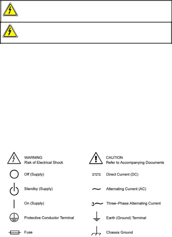
Safety Symbols
Product: Asterion Series Power Source

Asterion Series User Manual – 14U Models |
California Instruments |
Warranty Period: 1 Year
Warranty Terms
AMETEK Programmable Power, Inc. (“AMETEK”), provides this written warranty covering the Product stated above, and if the Buyer discovers and notifies AMETEK in writing of any defect in material or workmanship within the applicable warranty period stated above, then AMETEK may, at its option: repair or replace the Product; or issue a credit note for the defective Product; or provide the Buyer with replacement parts for the Product.
The Buyer will, at its expense, return the defective Product or parts thereof to AMETEK in accordance with the return procedure specified below. AMETEK will, at its expense, deliver the repaired or replaced Product or parts to the Buyer. Any warranty of AMETEK will not apply if the Buyer is in default under the Purchase Order Agreement or where the Product, or any part thereof, is as follows:
•damaged by misuse, accident, negligence or failure to maintain the same as specified or required by AMETEK;
•damaged by modifications, alterations or attachments thereto which are not authorized by AMETEK;
•installed or operated contrary to the instructions of AMETEK;
•opened, modified, or disassembled in any way without AMETEK’s consent;
•used in combination with items, articles or materials not authorized by AMETEK.
The Buyer may not assert any claim that the Products are not in conformity with any warranty until the Buyer has made all payments to AMETEK provided for in the Purchase Order Agreement.
Product Return Procedure
Request a Return Material Authorization (RMA) number from the repair facility (must be done in the country in which it was purchased):
•In the USA, contact the AMETEK Customer Service Department prior to the return of the product to AMETEK for repair:
Telephone: 800-733-5427, ext. 2295 or ext. 2463 (toll free North America) 858-450-0085, ext. 2295 or ext. 2463 (direct)
•Outside the United States, contact the nearest Authorized Service Center (ASC). A full listing can be found either through your local distributor, or on our website, www.programmablepower.com, by tapping Support button or going to the Service Centers tab.
When requesting an RMA, have the following information ready:
•Model number
•Serial number
•Description of the problem
NOTE: Unauthorized returns will not be accepted and will be returned at the shipper’s expense.
NOTE: A returned product found upon inspection by AMETEK to be in specification is subject to an evaluation fee and applicable freight charges.
M330511-01, REV-B |
5 |

Table of Contents
1. |
Introduction................................................................................................................................. |
13 |
||
|
1.1 |
General Description............................................................................................................................. |
14 |
|
|
1.2 |
Asterion Series Models ....................................................................................................................... |
15 |
|
2. |
Specifications ............................................................................................................................. |
17 |
||
|
2.1 |
Electrical Characteristics ..................................................................................................................... |
17 |
|
|
|
2.1.1 |
AC/DC Output Specifications .................................................................................................. |
17 |
|
|
2.1.2 iX2TM Constant-Power Mode Output Characteristic ................................................................ |
19 |
|
|
|
2.1.3 |
AC Input Specifications........................................................................................................... |
20 |
|
|
2.1.4 |
AC Output Measurements....................................................................................................... |
22 |
|
|
2.1.5 |
DC Output Measurements ...................................................................................................... |
23 |
|
|
2.1.6 |
Harmonics Measurements ...................................................................................................... |
24 |
|
|
2.1.7 |
Protection Function Characteristics ........................................................................................ |
24 |
|
2.2 |
Regulatory Agency Compliance .......................................................................................................... |
25 |
|
|
2.3 |
Environmental Specifications .............................................................................................................. |
25 |
|
|
2.4 |
Mechanical Specifications ................................................................................................................... |
26 |
|
|
2.5 |
Remote Control Digital Interface Characteristics................................................................................. |
26 |
|
|
2.6 |
Remote Control Analog/Digital Signal Characteristics......................................................................... |
27 |
|
|
2.7 |
Operational Characteristics ................................................................................................................. |
28 |
|
|
2.8 |
Front Panel Controls/Indicators ........................................................................................................... |
29 |
|
|
2.9 |
Rear Panel Connectors ....................................................................................................................... |
30 |
|
|
2.10 Firmware/Software Options ................................................................................................................. |
31 |
||
3. |
Installation................................................................................................................................... |
33 |
||
|
3.1 |
Unpacking ........................................................................................................................................... |
33 |
|
|
|
3.1.1 |
Contents of Shipment ............................................................................................................. |
33 |
|
3.2 |
Mechanical Installation ........................................................................................................................ |
34 |
|
|
|
3.2.1 |
Handling.................................................................................................................................. |
34 |
|
|
3.2.2 |
Rackmounting ......................................................................................................................... |
36 |
|
3.3 |
Outline Drawings ................................................................................................................................. |
38 |
|
|
3.4 |
Rear Panel Protective Covers ............................................................................................................. |
38 |
|
|
3.5 |
Input/output Connections .................................................................................................................... |
42 |
|
|
3.6 |
AC Input Connection ........................................................................................................................... |
43 |
|
|
|
3.6.1 AC Input Overcurrent Protection ............................................................................................. |
43 |
|
|
|
3.6.2 AC Input Safety Disconnect Device ........................................................................................ |
44 |
|
|
|
3.6.3 |
AC Input Connector ................................................................................................................ |
44 |
|
3.7 |
AC/DC Output Connection .................................................................................................................. |
47 |
|
|
|
3.7.1 Output Connection for 3-Phase Load...................................................................................... |
48 |
|
|
|
3.7.2 Output Connection for 1-Phase Load...................................................................................... |
49 |
|
|
3.8 |
Remote Sense Connection.................................................................................................................. |
50 |
|
|
3.9 |
Remote Sense..................................................................................................................................... |
51 |
|
|
3.10 Noise and Impedance Effects.............................................................................................................. |
51 |
||
|
3.11 Wire Gauge Selection ......................................................................................................................... |
52 |
||
|
|
3.11.1 |
Wire Size............................................................................................................................... |
52 |
|
3.12 Rear Panel User Interface Connectors................................................................................................ |
54 |
||
|
|
3.12.1 External Input/Output Control Signal Connector ................................................................... |
54 |
|
|
|
3.12.2 Summary Fault Signal (DFI).................................................................................................. |
57 |
|
|
|
3.12.3 |
Remote Inhibit Signal............................................................................................................ |
57 |
|
|
3.12.4 |
External Relay Interface........................................................................................................ |
58 |
|
|
3.12.5 External Interface Signal Connector ..................................................................................... |
59 |
|
|
|
3.12.6 Command Monitor and Trigger Output Connectors .............................................................. |
60 |
|
|
|
3.12.7 Clock and Lock Connectors (Option) .................................................................................... |
60 |
|
|
|
3.12.8 Master/Auxiliary System Interface Connectors ..................................................................... |
61 |
|
|
|
3.12.9 RS-232C Serial Interface Connector..................................................................................... |
62 |
|
|
|
3.12.10 |
USB Interface...................................................................................................................... |
63 |
|
|
3.12.11 |
LAN Interface (Ethernet) ..................................................................................................... |
64 |
|
3.13 Multiple Chassis System Configurations ............................................................................................. |
65 |
||
|
|
3.13.1 |
Multi-Phase System .............................................................................................................. |
65 |
|
|
3.13.2 |
Parallel System ..................................................................................................................... |
65 |

Asterion Series User Manual – 14U Models |
California Instruments |
|||
4. |
Operation |
.................................................................................................................................... |
69 |
|
|
4.1 |
Front Panel Operation ......................................................................................................................... |
69 |
|
|
|
4.1.1 .........................................................Front Panel Controls and Indicators, Enhanced Models |
70 |
|
|
|
4.1.2 ...................................................................Front Panel Controls and Indicators ATE Models |
71 |
|
|
4.2 |
Basic Output ..................................................................................................................Programming |
73 |
|
|
|
4.2.1 ...............................................................................................Front Panel Display Navigation |
73 |
|
|
|
4.2.2 ...................................................Selecting Output Characteristics and Adjusting Parameters |
73 |
|
|
4.3 |
Basic Functional ..........................................................................................................................Test |
74 |
|
|
4.4 |
Output ................................................................................................................Power Characteristic |
75 |
|
|
4.5 |
Front Panel ......................................................................................................Touch-Screen Display |
76 |
|
|
|
4.5.1 .............................................................................................. |
Touch - Screen Numeric Keypad |
77 |
|
|
4.5.2 ....................................................................................................................... |
Rotary Encoder |
77 |
|
4.6 |
Front Panel ..................................................................................................................Display Menus |
80 |
|
|
|
4.6.1 ..................................................................................DASHBOARD Screen Top-Level Menu |
82 |
|
|
|
4.6.2 .....................................................................OUTPUT PROGRAM Screen Top Level Menus |
84 |
|
|
|
4.6.3 .........................................................................MEASUREMENTS Screen Top-Level Menus |
89 |
|
|
|
4.6.4 ..................................................................................TRANSIENTS Screen Top-Level Menu |
95 |
|
|
|
4.6.5 .................................................................................................... |
CONFIGURATION Screen |
111 |
|
|
4.6.6 ........................................................................................... |
CONTROL INTERFACE Screen |
119 |
|
|
4.6.7 .......................................................................................................... |
PROTECTION Screen |
124 |
|
|
4.6.8 ........................................................................................................ |
APPLICATIONS Screen |
125 |
|
|
4.6.9 ................................................................................................ |
SYSTEM SETTINGS Screen |
126 |
5. |
Waveform ...........................................................................................................Management |
129 |
||
|
5.1 |
Standard .........................................................................................................................Waveforms |
129 |
|
|
5.2 |
Creating .............................................................................................................Custom Waveforms |
129 |
|
|
|
5.2.1 ..........................................................................Viewing Custom Waveforms on the Display |
130 |
|
|
5.3 |
RMS Amplitude ..............................................................................................................Restrictions |
130 |
|
|
5.4 |
Frequency .....................................................................................................Response Restrictions |
131 |
|
|
5.5 |
Transient ..................................................................................................................List Waveforms |
131 |
|
6. |
Standard Measurements ......................................................................................................... |
133 |
||
|
6.1 |
Parameter .................................................................................................................Measurements |
133 |
|
|
|
6.1.1 ....................................................................................................... |
Accuracy Considerations |
134 |
|
6.2 |
Advanced ..................................................................................................................Measurements |
134 |
|
|
|
6.2.1 ................................................................................................................. |
Harmonic Analysis |
134 |
|
|
6.2.2 ................................................................................................................ |
Acquiring FFT data |
134 |
|
|
6.2.3 ............................................................................................................... |
Analyzing FFT Data |
135 |
|
6.3 |
Triggering ..................................................................................................................Measurements |
136 |
|
|
|
6.3.1 ......................................................................................................................... |
Trigger Mode |
136 |
|
|
6.3.2 ....................................................................................................................... |
Trigger source |
136 |
|
|
6.3.3 ......................................................................................................................... |
Trigger delay |
137 |
7. |
Transient ..........................................................................................................Programming |
139 |
||
|
7.1 |
Using Transient ......................................................................................................................Modes |
139 |
|
|
|
7.1.1 ..................................................................................................................... |
Step Transients |
140 |
|
|
7.1.2 ................................................................................................................... |
Pulse Transients |
140 |
|
|
7.1.3 ....................................................................................................................... |
List Transients |
141 |
|
7.2 |
Programming ..................................................................................................................Slew Rates |
142 |
|
|
7.3 |
Switching ............................................................................................Waveforms in Transient Lists |
143 |
|
|
7.4 |
Saving .........................................................................................................Transient List Programs |
144 |
|
8. |
Calibration ................................................................................................................................ |
145 |
||
|
8.1 |
Calibration .......................................................................................................................Equipment |
145 |
|
|
8.2 |
Calibration ......................................................................................................................Procedures |
145 |
|
|
|
8.2.1 .................................................................................................... |
Preparation for Calibration |
145 |
|
|
8.2.2 ......................................................................Output Voltage AC Zero Alignment, AC-Mode |
146 |
|
|
|
8.2.3 ......................................................................Output Voltage DC Zero Alignment, DC-Mode |
146 |
|
|
|
8.2.4 ...........................................Output Voltage Gain Initial Alignment, AC-Mode and DC-Mode |
147 |
|
|
|
8.2.5 ...............................................Output Voltage Measurement AC Gain Alignment, AC-Mode |
148 |
|
M330511-01, REV-B |
7 |
|
8.2.6 Output Voltage Measurement DC-Positive Gain Alignment, DC-Mode................................. |
148 |
|
|
8.2.7 Output Voltage Measurement DC-Negative Gain Alignment, DC-Mode ............................... |
149 |
|
|
8.2.8 Output Current Measurement AC Low-Range Gain Alignment, AC-Mode............................ |
149 |
|
|
8.2.9 Output Current Measurement AC High-Range Gain Alignment, AC-Mode........................... |
150 |
|
|
8.2.10 Output Current Measurement AC Low-Range Offset Alignment, AC-Mode........................ |
151 |
|
|
8.2.11 Output Current Measurement AC High-Range Offset Alignment, AC-Mode....................... |
151 |
|
|
8.2.12 Output Current Measurement DC-Positive Low-Range Gain Alignment, DC-Mode............ |
152 |
|
|
8.2.13 Output Current Measurement DC-Positive High-Range Gain Alignment, DC-Mode........... |
152 |
|
|
8.2.14 Output Current Measurement DC-Negative Low-Range Gain Alignment, DC-Mode .......... |
153 |
|
|
8.2.15 Output Current Measurement DC-Negative High-Range Gain Alignment, DC-Mode ......... |
153 |
|
|
8.2.16 Output Current Measurement Low-Range Offset Alignment, DC-Mode ............................. |
154 |
|
|
8.2.17 Output Current Measurement High-Range Offset Alignment, DC-Mode............................. |
155 |
|
|
8.2.18 Output Phase-A Alignment, Output Relative to External SYNC.......................................... |
156 |
|
|
8.2.19 Output Phase-A Alignment, Auxiliary Unit Relative to Master Unit (LKS Option Only)........ |
156 |
|
|
8.2.20 Output Phase-B and Phase-C Alignment Relative to Phase-A ........................................... |
157 |
|
|
8.2.21 Alignment of External Programming Signal for Output Voltage Waveform/Amplitude ........ |
158 |
|
|
8.2.22 Alignment of External Programming Signal for Output Voltage Amplitude, DC Output....... |
159 |
|
|
8.2.23 Alignment of External Programming Signal for Output Voltage Amplitude, AC output........ |
160 |
|
9. Service....................................................................................................................................... |
|
163 |
|
9.1 |
Cleaning ............................................................................................................................................ |
163 |
|
9.2 |
Basic Troubleshooting....................................................................................................................... |
163 |
|
|
9.2.1 |
Excessive Output Voltage..................................................................................................... |
163 |
|
9.2.2 Poor Output Voltage Regulation ........................................................................................... |
163 |
|
|
9.2.3 FAULT LED is On ................................................................................................................. |
163 |
|
|
9.2.4 |
Distorted Output.................................................................................................................... |
164 |
|
9.2.5 Unit Shuts Down after Short Interval..................................................................................... |
164 |
|
|
9.2.6 No Output and Front Panel Display/LEDs are Off................................................................. |
164 |
|
|
9.2.7 No Output and Front Panel Display/LEDs are On................................................................. |
164 |
|
|
9.2.8 Setting of AC/DC Mode or Voltage Range is Not Accepted.................................................. |
164 |
|
|
9.2.9 Parallel Group Faults When Master Output Switch is Turned On ......................................... |
164 |
|
10. Error and Status Messages..................................................................................................... |
165 |
||
Index ................................................................................................................................................. |
|
|
171 |

Asterion Series User Manual – 14U Models |
California Instruments |
|
List of Figures |
|
|
Figure 1-1. 14U-Asterion Series Front View ........................................................................................................ |
|
13 |
Figure 2-1. iX2TM Constant-Power: Output Current Versus Voltage, AST 12K3 and AST18K3........................... |
19 |
|
Figure 3-1. Shipping Strap Installation................................................................................................................. |
|
35 |
Figure 3-2. Rackmounting Installation ................................................................................................................. |
|
36 |
Figure 3-3. Rackmount Kit Installation (Option)................................................................................................... |
|
37 |
Figure 3-4. Rear Panel Output Sense Protective Cover Installation .................................................................... |
|
38 |
Figure 3-5. Rear Panel Input/Output Protective Cover Installation ...................................................................... |
|
39 |
Figure 3-6. Installation Drawing, Enhanced Model .............................................................................................. |
|
40 |
Figure 3-7. Installation Drawing ATE Models ...................................................................................................... |
|
41 |
Figure 3-8. Rear Panel View (with GPIB and LKM/LKS options)......................................................................... |
|
42 |
Figure 3-9. AC Input Connector and Safety-Ground Stud, for 3-Wire plus Ground Input .................................... |
|
44 |
Figure 3-10. AC Input Connector and Safety-Ground Stud, for 4-Wire (with Neutral) plus Ground Input ............ |
45 |
|
Figure 3-11. AC/DC Output Connector and Functional-Ground .......................................................................... |
|
47 |
Figure 3-12. Output Connection to 3-Phase Load ............................................................................................... |
|
48 |
Figure 3-13. Output Connection to 1-Phase Load ............................................................................................... |
|
49 |
Figure 3-14. Remote Sense Connector and Functional-Ground ......................................................................... |
|
50 |
Figure 3-15. External Input/Output Control Connector ........................................................................................ |
|
54 |
Figure 3-16. External Relay Interface Connector................................................................................................. |
|
58 |
Figure 3-17. External Relay Interface for 1-Phase Relay Control ........................................................................ |
|
59 |
Figure 3-18. External Interface Signal Connector................................................................................................ |
|
59 |
Figure 3-19. External Command Monitor and Trigger Output Connectors .......................................................... |
|
60 |
Figure 3-20. External Clock/Lock Interface Connectors (Option)......................................................................... |
|
60 |
Figure 3-21. External Master/Auxiliary System Interface Connectors.................................................................. |
|
61 |
Figure 3-22. RS-232C Interface Connector ......................................................................................................... |
|
62 |
Figure 3-23. USB Interface Connector ................................................................................................................ |
|
63 |
Figure 3-24. LAN Interface 8P8C Modular Connector ......................................................................................... |
|
64 |
Figure 3-25. Connections for 3-Phase Parallel Group ......................................................................................... |
|
67 |
Figure 3-26. Connections for 3-Phase Master/Auxiliary Multi-Phase Group........................................................ |
|
68 |
Figure 4-1. Front Panel, Enhanced Models ......................................................................................................... |
|
69 |
Figure 4-2. Front Panel, ATE Models .................................................................................................................. |
|
71 |
Figure 4-3. iX2TM Constant-Power Output Characteristic .................................................................................... |
|
75 |
Figure 4-4. HOME Screen ................................................................................................................................... |
|
76 |
Figure 4-5. DASHBOARD Screen Menu with Voltage Selection-Field Active ..................................................... |
|
76 |
Figure 4-6. Menu with Only Phase-A Selected.................................................................................................... |
|
77 |
Figure 4-7. Touch-Screen Numeric Keypad ........................................................................................................ |
|
77 |
Figure 4-8. Rotary Encoder ................................................................................................................................. |
|
78 |
Figure 4-9. Output Program Menu Selection-Fields with Phase Number Highlighted ......................................... |
|
78 |
Figure 4-10. Highlighted Voltage Selection-Field with Value Window ................................................................. |
|
79 |
Figure 4-11. Power-On Screens .......................................................................................................................... |
|
80 |
Figure 4-12. HOME Screen ................................................................................................................................. |
|
81 |
Figure 4-13. DASHBORD Screen Top-Level Menu............................................................................................. |
|
82 |
Figure 4-14. Real-Time, Immediate Output Parameter Adjustment..................................................................... |
|
83 |
Figure 4-15. Default Screen ................................................................................................................................ |
|
84 |
Figure 4-16. OUTPUT PROGRAM Screen Top-Level Menu............................................................................... |
|
84 |
Figure 4-17. MEASUREMENTS Screen Top-Level Menu................................................................................... |
|
89 |
Figure 4-18. HARMONICS Menu ........................................................................................................................ |
|
92 |
Figure 4-19. HARMONICS Menu, Table View..................................................................................................... |
|
94 |
Figure 4-20. HARMONICS Menu, Bar Graph View ............................................................................................. |
|
94 |
Figure 4-21. TRANSIENTS Screen Top-Level Menu .......................................................................................... |
|
95 |
Figure 4-22. SETTINGS Menu ............................................................................................................................ |
|
95 |
Figure 4-23. SETTINGS Screen, TRIGGER Sub-Menu ...................................................................................... |
|
97 |
Figure 4-24. VIEW Menu, With Empty Buffer ...................................................................................................... |
|
98 |
Figure 4-25. VIEW Menu, With Transient List Entry ............................................................................................ |
|
98 |
Figure 4-26. VIEW Menu, ADD Sub-Menu .......................................................................................................... |
|
99 |
Figure 4-27. VIEW Menu, VOLTAGE DROP Sub-Menu ................................................................................... |
|
102 |
Figure 4-28. VIEW Menu, VOLTAGE SWEEP/STEP Sub-Menu....................................................................... |
|
103 |
Figure 4-29. VIEW Menu, VOLTAGE SURGE/SAG Sub-Menu......................................................................... |
|
104 |
Figure 4-30. VIEW Menu, FREQUENCY SWEEP/STEP Sub-Menu ................................................................. |
|
105 |
Figure 4-31. VIEW Menu, FREQUENCY SURGE/SAG Sub-Menu ................................................................... |
|
106 |
Figure 4-32. VIEW Menu, VOLT/FREQ SWEEP/STEP Sub-Menu ................................................................... |
|
107 |
M330511-01, REV-B |
9 |
Figure 4-33. VIEW Menu, VOLT/FREQ SURGE/SAG Sub-Menu..................................................................... |
108 |
Figure 4-34. VIEW Menu, DELAY Sub-Menu.................................................................................................... |
109 |
Figure 4-35. RUN Menu .................................................................................................................................... |
110 |
Figure 4-36. CONFIGURATION Screen Top-Level Menu................................................................................. |
111 |
Figure 4-37. CONFIGURATION Menu, PROFILES Sub-Menu......................................................................... |
112 |
Figure 4-38. PROFILES Menu, NAME Sub-Menu ............................................................................................ |
112 |
Figure 4-39. CONFIGURATION Menu, PONS Menu-1/2.................................................................................. |
114 |
Figure 4-40. CONTROL INTERFACE Screen................................................................................................... |
119 |
Figure 4-41. CONTROL INTERFACE Menu, ANALOG Sub-Menu................................................................... |
120 |
Figure 4-42. CONTROL INTERFACE Menu, RS232 Sub-Menu....................................................................... |
120 |
Figure 4-43. CONTROL INTERFACE Menu, GPIB Sub-Menu ......................................................................... |
121 |
Figure 4-44. CONTROL INTERFACE, LAN Menu ............................................................................................ |
121 |
Figure 4-45. CONTROL INTERFACE, LAN CONFIGURE Sub-Menu .............................................................. |
122 |
Figure 4-46. CONTROL INTERFACE REMOTE INHIBIT Menu ....................................................................... |
124 |
Figure 4-47. PROTECTION Screen .................................................................................................................. |
124 |
Figure 4-48. APPLICATIONS Screen, Output Impedance Example ................................................................. |
125 |
Figure 4-49. SYSTEM SETTINGS Screen ........................................................................................................ |
126 |
Figure 4-50. SYSTEM SETTINGS Menu, LCD Menu ....................................................................................... |
127 |
Figure 5-1. HARMONICS Screen, Waveform Information................................................................................. |
130 |
Figure 6-1. HARMONICS Menu ........................................................................................................................ |
134 |
Figure 6-2. FFT data in Tabular Format ............................................................................................................ |
135 |
Figure 6-3. FFT data in Bar Graph Format........................................................................................................ |
135 |
Figure 6-4. HARMONICS Menu, Triggering ...................................................................................................... |
136 |
Figure 6-5. Post-Trigger (Positive Delay) .......................................................................................................... |
137 |
Figure 6-6. Pre-Trigger (Negative Delay ........................................................................................................... |
138 |
Figure 7-1. Output Transient Modes.................................................................................................................. |
140 |
Figure 7-2. Pulse Transients ............................................................................................................................. |
141 |
Figure 7-3. List Transients................................................................................................................................. |
141 |
Figure 7-4. Switching Waveforms in a Transient List Transient Execution........................................................ |
143 |
Figure 7-5. RUN Menu: Start and Abort Fields.................................................................................................. |
143 |
Figure 7-6. CONFIGURATION Menu, PROFILES Selection............................................................................. |
144 |
Asterion Series User Manual – 14U Models |
California Instruments |
|
List of Tables |
|
|
Table 3-1. Rackmount Kit Parts List (Option) ...................................................................................................... |
|
38 |
Table 3-2. AC Input Connector Pinout and Safety-Ground, for 3-Wire plus Ground Input................................... |
|
45 |
Table 3-3. AC Input Connector Pinout and Safety-Ground, for 4-Wire (with Neutral) plus Ground Input |
............46 |
|
Table 3-4. AC Input Connector Type ................................................................................................................... |
|
46 |
Table 3-5. AC/DC Output Connector Pinout and Functional-Ground .................................................................. |
|
47 |
Table 3-6. AC/DC Output Connector Type and Functional-Ground..................................................................... |
|
48 |
Table 3-7. Remote Sense Connector Pinout ....................................................................................................... |
|
50 |
Table 3-8. Remote Sense Connector Type ......................................................................................................... |
|
50 |
Table 3-9. Minimum Wire Size............................................................................................................................. |
|
52 |
Table 3-10. Wire Resistance and Voltage Drop, 20 °C........................................................................................ |
|
53 |
Table 3-11. External Input/Output Control Connector Type................................................................................. |
|
54 |
Table 3-12. External Input/Output Control Functions........................................................................................... |
|
55 |
Table 3-13. External Input/ Output Control Connector Pinout ............................................................................. |
|
56 |
Table 3-14. External Relay Interface Connector Type......................................................................................... |
|
58 |
Table 3-15. External relay interface Connector Pinout. ....................................................................................... |
|
58 |
Table 3-16. External Interface Signal Connector Type ........................................................................................ |
|
59 |
Table 3-17. External Command Monitors and Trigger Output Characteristics .................................................... |
|
60 |
Table 3-18. External Clock/Lock Interface Characteristics (Option) .................................................................... |
|
61 |
Table 3-19. External Master/Auxiliary System Interface Connector Type............................................................ |
|
61 |
Table 3-20. External Master/Auxiliary System Interface Characteristics ............................................................. |
|
62 |
Table 3-21. RS-232C Interface Connector Type ................................................................................................. |
|
62 |
Table 3-22. RS-232C Interface Connector Pinout ............................................................................................... |
|
62 |
Table 3-23. USB Interface Connector Pinout ...................................................................................................... |
|
63 |
Table 3-24. LAN Interface 8P8C Modular Connector Pinout ............................................................................... |
|
64 |
Table 4-1. Front Panel Controls and Indicators, Enhanced Models..................................................................... |
|
70 |
Table 4-2. Front Panel Controls and Indicators, ATE Models.............................................................................. |
|
72 |
Table 4-3. HOME Screen Menu Content............................................................................................................. |
|
81 |
Table 6-1. MEASUREMENTS Screen Parameters ........................................................................................... |
|
133 |
Table 6-2. MEASUREMENTS Parameter Value Derivation .............................................................................. |
|
133 |
Table 8-1. Calibration Equipment ...................................................................................................................... |
|
145 |
Table 8-2. Load Values for Output AC Current Alignment................................................................................. |
|
155 |
Table 8-3. Load Values for Output DC Current Alignment................................................................................. |
|
155 |
Table 10-1. Error and Status Messages ............................................................................................................ |
|
169 |
M330511-01, REV-B |
11 |

Asterion Series User Manual – 14U Models |
California Instruments |
1. Introduction
This instruction manual contains information on the installation, operation, and calibration of the
Asterion Series power source models with 1-phase/3-phase output in a 14U chassis. The Asterion Series is the latest generation of switched-mode power sources that provide precise output having high accuracy, low distortion, and fast dynamic response. With extensive programmability and user interface, it offers a rich feature set and functionality: AC and DC output capability, wide output frequency range, arbitrary and harmonic waveform generation, sequencing of transient lists, digital power analyzer measurements, real-time waveform display, and the capability to be configured in systems comprised of multi-phase and parallel groups.
Figure 1-1. 14U-Asterion Series Front View
M330511-01, REV-B |
13 |

Asterion Series User Manual – 14U Models |
California Instruments |
1.1 General Description
The Asterion Series power sources are available in a 14U chassis at power levels of 12000 VA and 18000 VA. Two AC output voltage ranges are provided, 0-200 VAC/0-400 VAC, with a frequency range of 16 Hz-1200 Hz (with up to 5000 Hz as an option), two DC output ranges, 0-250 VDC/0-500 VDC, and a combined AC+DC mode. A wide range of AC and DC loads could be powered, including reactive loads (inductive and capacitive) running at full rated apparent power, and non-linear loads drawing current with high crest factor, up to 5:1.
The output has an iX2TM constant-power characteristic that provides greater output current at reduced output voltage: up to 2X at 50% of full-scale voltage. The Asterion 14U models support two types of AC inputs, one type being 200-240 VAC, 3-phase, 3-wire plus ground, and the other being
220/380 VAC - 240/415 VAC, 3-phase, 4-wire (with neutral) plus ground. AC input frequency is either 50/60 Hz. The Asterion 14U models provide power factor correction of the AC input with low input current harmonics, producing PF of 0.95/0.98, 3-wire/4-wire. Two 14U units can be connected in parallel or in multi-phase groups, with outputs of up to 36 kVA.
Multiple remote digital communications interfaces are available: standard LAN (Ethernet), USB, and RS-232C, or the optional IEEE-488 (GPIB) interface. The Asterion Virtual Panels GUI program provides a convenient graphical user interface, and the SCPI command set allows access to the full programmability and functionality. Extensive remote analog and discrete digital control interfaces are also provided for specialized control applications. The front panel display has capability for control, programming, and measurements of the power source, and features a menu-based interface with touch-screen data/command entry.
Waveform generation includes standard sine wave and square wave, and extensive programmability to produce complex waveforms based on harmonics or arbitrary parameter value/time relationships. A transient generator could combine sequences of voltage, frequency, and wave shape to simulate real-world AC or DC disturbances and automate a complex profile of power stimulus to the unit under test.
The power analyzer utilizes DSP-based digitization of output parameters to implement measurement functions spanning single parameter values (voltage/current/frequency), power characteristics (true/apparent power, crest factor, power factor), and advanced computation using fast Fourier transform (FFT) derivation of the harmonics and distortion contained in the voltage and current waveforms. Real-time display of output waveforms is possible through the front panel display or the
Asterion Virtual Panels GUI.
14 |
M330511-01, REV-B |

Asterion Series User Manual – 14U Models |
California Instruments |
1.2 Asterion Series Models
AST 18K 3 A 1 C – E 0 0 0A 00
Series
Asterion
Output Power
12K = 12000 W
18K = 18000 W
Output Phases
3 = 3-Phase
Product Family
A = Standard, C= No Casters
Number of Chassis
1 = 1 Chassis, 2 = 2 Chassis
Input Voltage
C = 200-240 VAC, 3-Phase, 3-Wire + GND
D = 220/380 VAC-240/415 VAC, 3-Phase,
4-Wire (with Neutral) + GND
Front Panel
E = Enhanced
Interface Options
0 = None
1 = GPIB
2 = GPIB - MC
Avionics Test Options |
|
|
|
|
|
|
|||
|
|
|
|
|
|
||||
0 |
= None |
6 = B787 – MC |
C= AVSTD & AMD |
|
|
||||
1 |
= B787 |
7 = AMD – MC |
D= AVSTD & B787-MC |
|
|
||||
2 |
= AMD |
8 = B787 - AMD – MC |
E= AVSTD & AMD -MC |
|
|
||||
3 |
= B787 - AMD |
9 = AVSTD - MC |
|
|
|
|
|||
4 |
= AVSTD |
A = AVALL - MC |
|
|
|
|
|||
5 |
= AVALL |
B= AVSTD & B787 |
|
|
|
|
|||
Frequency and Clock/Lock Options |
|
|
|
|
|
||||
|
|
|
|
|
|||||
0A |
= None |
2B = HF – LKM 3B = HF - FC - LKS |
|
|
|||||
1A |
= HF |
2C = HF - LKS |
|
|
|
|
|||
1B |
= LF |
2D = LF - LKM |
|
|
|
|
|||
1C = FC |
2E = LF - LKS |
|
|
|
|
||||
1D = LKM |
2F = FC - LKM |
|
|
|
|
||||
1E |
= LKS |
2G = FC - LKS |
|
|
|
|
|||
2A |
= HF - FC |
3A = HF - FC - LKM |
|
|
|
|
|||
Other Options |
|
|
|
|
|
|
|
||
|
|
|
|
|
|
|
|||
0A |
= None |
1G = 1399 - MC |
2G = 411 - 1399 |
3C = MB - 411 - 1399 |
|||||
1A |
= 411 |
2A = 411 - 413 |
2H = 413 - 1399 |
3D = MB - 41 - 1399 - MC |
|||||
1B |
= 413 |
2B = MB - 411 |
2I = MB - 1399 |
3E = MB - 413 - 1399 |
|||||
1C = MB |
2C = MB - 413 |
2J = 411 - 1399 - MC |
3F = MB - 413 - 1399 – MC |
||||||
1D = 411 - MC |
2D = 411 - 413 - MC |
2K = 413 - 1399 - MC |
3G = 411 & 4131399 |
||||||
1E |
= 413 - MC |
2E = MB - 411 - MC |
2L = MB - 1399 - MC |
3H = 411 & 4131399 - MC |
|||||
1F = 1399 |
2F = MB - 413 - MC |
3A = MB - 411 - 413 |
4A = MB - 411 - 413 - 1399 |
||||||
|
|
|
|
|
|
3B = MB - 411 - 413 - MC |
4B = MB - 411 - 413 - 1399 - MC |
||
M330511-01, REV-B |
15 |

Asterion Series User Manual – 14U Models |
California Instruments |
2. Specifications
Unless otherwise noted, the specifications are valid under the following conditions:
1.Ambient temperature of 25 ± 5°C, after a 30-minute warm-up, and at fixed AC input line and load;
2.Individual unit and individual output phase, with sine wave output, and into a resistive load;
3.For system configurations, specifications are for phase output, line-to-neutral; phase angle specifications are valid under balanced resistive load conditions.
2.1 Electrical Characteristics
2.1.1AC/DC Output Specifications
Model |
|
AST 12K3 |
|
AST 18K3 |
|
|
|
|
|
Enclosure |
14U |
14U |
||
|
|
|
|
|
Output Phase |
|
1-Phase/3-Phase |
|
1-Phase/3-Phase |
|
|
|
||
Output Power |
12,000 VA/12000 W; |
18,000 VA/ 18,000 W; |
||
|
4000 W, maximum per phase |
6,000 W, maximum per phase |
||
|
|
|
|
|
|
|
Low-Range: |
|
Low-Range: |
|
|
20 A(RMS) at 200 VAC; |
|
30 A (RMS) at 200 VAC; |
AC and AC+DC |
|
40 A1 (RMS) at 100 VAC |
|
60 A1 (RMS) at 100 VAC |
Output Current, |
|
High-Range: |
|
High-Range: |
Full-Scale, |
|
|
||
|
10 A(RMS) at 400 VAC; |
|
15 A (RMS) at 400 VAC; |
|
per Phase |
|
|
||
|
|
20 A(1) (RMS) at 200 VAC |
|
30 A1 (RMS) at 200 VAC |
|
1-Phase output mode: rating times 3. |
1-Phase output mode: rating times 3. |
||
|
|
|
|
|
|
|
Low-Range: |
Low-Range: |
|
DC Output Current, |
|
16 ADC at 250 VDC; |
24 ADC at 250 VDC; |
|
|
32 ADC1 at 125 VDC |
48 ADC1 at 125 VDC |
||
Full-Scale, |
|
High-Range: |
|
High-Range: |
per Phase |
|
|
||
|
8 ADC at 500 VDC; |
|
12 ADC at 500 VDC; |
|
|
|
|
||
|
|
16 ADC1 at 250 VDC |
|
24 ADC1 at 250 VDC |
|
|
1-Phase output mode: rating times 3. |
|
1-Phase output mode: rating times 3. |
|
|
|
||
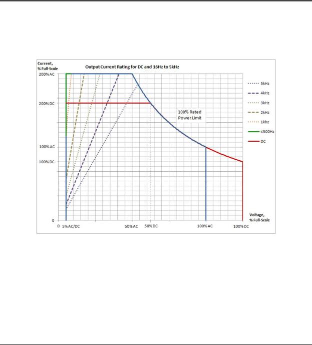
1 Refer to “iX2TM Constant-Power Mode Output Characteristic” on Section 2.1.2. |
||||
|
|
All Models |
|
|
Output Current, |
200% of the full-scale RMS current at ≤50% of full-scale voltage. Refer to Figure 2-1 for |
|||
Maximum RMS |
|
current rating as a function of output voltage and frequency. |
||
|
Constant-Power output capability in each output voltage range with full rated output |
|||
iX2TM |
|
power from 50% of full-scale output voltage to 100% of full-scale; the output current |
||
Constant-Power |
|
increases to 200% of rated current at 50% full-scale output voltage from 100% rated |
||
Mode |
|
current at 100% of full-scale voltage. Refer to Figure 2-1 for current rating as a function |
||
|
|
of output frequency. |
|
|
AC and AC+DC |
|
Low-Range: 0 to 200 V(RMS); High-Range: 0 to 400 V(RMS) |
||
Output Voltage, |
HF Option: derate full-scale output voltage from 4 kHz to 5 kHz, as follows. |
|||
Full-Scale |
|
|
|
|
DC Output Voltage, |
Low-Range: 0 to 250 VDC; High-Range: 0 to 500 VDC |
|||
Full-Scale |
|
|
|
|
|
|
|
|
|
M330511-01, REV-B |
17 |
Asterion Series User Manual – 14U Models |
California Instruments |
||||||
|
|
|
|
|
|
|
|
|
DC Offset Voltage, |
±20 mVDC, ≥40 Hz |
|
|
|
|
|
|
Typical |
|
|
|
|
|
|
|
Output Float Voltage |
566 V(PK), maximum from either output terminal to chassis |
|
|
|
||
|
|
|
|
||||
|
|
|
± (0.1% of actual + 0.2% of full-scale) for DC, and AC 16 Hz to 1.2 kHz, add ±0.1% of full |
||||
|
Voltage Accuracy |
scale for AC+DC mode; >1.2 kHz, add ±0.2% of full-scale/kHz; Valid from 5% of |
|||||
|
full-scale to 200 VAC(RMS)/250 VDC in low-range and 400 VAC(RMS)/500 VDC in |
||||||
|
|
|
|||||
|
|
|
high-range; with sense leads connected. |
|
|
|
|
|
|
|
|
|
|
|
|
|
Voltage Resolution |
≤0.02 V, AC, DC, and AC+DC mode |
|
|
|
|
|
|
|
|
|
|
|
|
|
|
Voltage Temperature |
≤100 ppm/°C of full-scale |
|
|
|
|
|
|
Coefficient, Typical |
|
|
|
|
|
|
|
Voltage Stability, |
±0.1% of full-scale over 8 hours; with constant line, load, and temperature; |
|||||
|
Typical |
with sense leads connected |
|
|
|
|
|
|
Voltage Distortion |
0.25% maximum, 16 Hz to 100 Hz; 0.5% maximum, >100Hz to 500 Hz; and |
|||||
|
1% maximum, >500 Hz to 1.2 kHz, plus 0.5%/kHz to 5 kHz; at full linear load or no load; |
||||||
|
|
|
valid for output voltage >5% of full-scale at full load, and >15% of full-scale at no load. |
||||
|
|
|
|
|
|
|
|
|
Voltage Slew Rate, |
≥10 V/µs with full-scale programmed voltage step |
|
|
|
|
|
|
Typical |
|
|
|
|
|
|
|
|
|
|
||||
|
Current |
Programmable from zero to 200% of full-scale rating in each output range. Refer to |
|||||
|
Programming Range |
Figure 2-1 for current rating as a function of output voltage and frequency. |
|||||
|
|
|
±(0.3% of actual + 0.5% of full-scale) for DC, and AC 16 Hz to 1.2 kHz; add ±0.1% of |
||||
|
Current |
full-scale for AC+DC mode. Valid from 5% of full-scale to 100% of full-scale. |
|||||
|
HF option: for High-Range, add 1.2% of maximum/kHz; for Low-Range, add 0.1% of |
||||||
|
Programming |
||||||
|
Accuracy |
chassis. |
√1.5 |
|
|
||
|
maximum/kHz. Valid from 20% of full-scale to 200% of full-scale. |
|
|
||||
|
|
|
For multi-chassis configurations, multiply the accuracy by |
|
, where |
is number of |
|
|
|
|
|
||||
|
Line Regulation |
±0.015% of full-scale voltage, for a ±10% input line change; DC, or 40 Hz to 5 kHz. |
|||||
|
|
|
|
||||
|
Load Regulation |
±0.025% of full-scale voltage, for 100% of rated resistive load change; DC, or 40 Hz to |
|||||
|
1.2 kHz, above 1.2 kHz, add ±0.015% of full-scale/kHz |
|
|
|
|
||
|
|
|
|
|
|
|
|
|
V/I Programming |
1% of full-scale |
|
|
|
|
|
|
Overrange, Typical |
|
|
|
|
|
|
|
|
|
AC output: 450 mV(RMS), low-range; 750 mV(RMS), high-range; |
|
|
||
|
Noise Level, Typical |
at ≥40 Hz output frequency; bandwidth, 20 kHz to 1 MHz; |
|
|
|
|
|
|
DC output: 400 mV(RMS), low-range; 700 mV(RMS), high-range; |
|
|
||||
|
|
|
|
|
|||
|
|
|
bandwidth, 20 Hz to 1 MHz. |
|
|
|
|
|
|
|
|
|
|
|
|
|
Remote Sense |
5 V(RMS), maximum total output lead drop |
|
|
|
|
|
|
|
|
|
||||
|
Crest Factor |
AST12K3, AST18K3: 5:1 of full-scale current in each output range (ratio of peak output |
|||||
|
current to RMS full-scale output current). |
|
|
|
|
||
|
|
|
|
|
|
|
|
|
Power Factor |
0, lagging to 0, leading |
|
|
|
|
|
|
|
|
|
|
|
|
|
|
Frequency Range |
Standard models: DC, and 16 Hz to 1.2 kHz; |
|
|
|
|
|
|
LF option: DC, and 16 Hz to 550 Hz; |
|
|
|
|
||
|
|
|
|
|
|
|
|
|
|
|
HF option: DC, and 16 Hz to 5 kHz. |
|
|
|
|
|
|
|
|
|
|
|
|
|
Frequency Accuracy |
|
Standard models: ±(0.01% of actual + frequency resolution/2) |
|
|
|
|
|
|
FC option: ±0.25% |
|
|
|
|
|
|
|
|
|
|
|
|
|
|
|
|
|
|
|
|
|
|
|
|
0.01 Hz resolution, 16-81.91 Hz; |
|
|
|
|
|
Frequency |
|
0.1 Hz resolution, 82-819.1 Hz; |
|
|
|
|
|
Resolution |
|
1 Hz resolution, 820-5000 Hz; |
|
|
|
|
|
|
|
with LKM/LKS option: 1 Hz resolution, 16-5000 Hz. |
|
|
|
|
18 |
M330511-01, REV-B |
Asterion Series User Manual – 14U Models |
California Instruments |
|||
|
|
|
|
|
|
Frequency |
10 ppm/ºC of full-scale in each range |
|
|
|
Temperature |
|
|
|
|
Coefficient, Typical |
|
|
|
|
Phase Programming |
0.0 º to 360.0 º, relative to external synchronization signal; in multi-phase group, Auxiliary |
||
|
unit output voltage is relative to the Master unit output voltage, with the Master unit as |
|||
|
Range |
|||
|
reference 0°. |
|
|
|
|
|
|
|
|
|
|
|
||
|
Phase Accuracy |
±1º, 16 Hz to 100 Hz; ±2º >100 Hz to 1.2 kHz, plus ±1º/kHz above 1.2 kHz |
||
|
|
|
|
|
|
Phase Programming |
±0.4º |
|
|
|
Resolution |
|
|
|
2.1.2iX2TM Constant-Power Mode Output Characteristic
The iX2TM Constant-Power mode has an output characteristic where full rated output power is available from 50% of full-scale output voltage to 100% of full-scale output voltage, as depicted in the graph of Figure 2-1. The output current versus output voltage follows a constant-power relation where the output current would be 200% of the full-scale value when the output voltage is 50% of full-scale. The current ratings are also a function of output frequency, as shown in Figure 2-1 above 500 Hz for the AST12K3 and AST18K3 units.
Figure 2-1. iX2TM Constant-Power: Output Current Versus Voltage, AST 12K3 and
AST18K3
M330511-01, REV-B |
19 |

Asterion Series User Manual – 14U Models |
California Instruments |
2.1.3AC Input Specifications
|
Model |
|
AST 12K3 |
|
AST 18K3 |
|
|
|
|
|
|
|
|
|
Enclosure |
14U |
14U |
|||
|
|
|
|
|
||
|
Input Voltage type |
|
3-Phase, 3-Wire + GND, or |
3-Phase, 3-Wire + GND, or |
||
|
(Only Factory |
3-Phase, 4-Wire (with Neutral) + GND |
3-Phase, 4-Wire (with Neutral) + GND |
|||
Configurable) |
||||||
|
|
|
|
|||
|
Input Voltage, |
|
200-240 VAC, 3-Phase, Line-Line |
|
200-240 VAC, 3-Phase, Line-Line |
|
|
Nominal Rating for |
|
|
|
|
|
|
3-phase, 3-Wire + GND |
|
|
|
|
|
|
Input |
|
|
|
|
|
|
Input Voltage, |
|
180-264 VAC, 3-Phase, |
|
180-264 VAC, 3-Phase, |
|
|
Operating Range for |
|
3-Wire, Line-Line |
|
3-Wire, Line-Line |
|
|
3-phase, 3-Wire + GND |
|
|
|
|
|
|
Input |
|
|
|
|
|
|
Input Voltage, |
220/380 VAC-240/415 VAC, 3-Phase, |
|
220/380 VAC-240/415 VAC, 3-Phase, |
||
|
Nominal Rating for |
4-Wire, Neutral required |
|
4-Wire, Neutral required |
||
|
3-Phase, 4-Wire (with |
|
|
|
|
|
Neutral) + GND Input |
|
|
|
|
||
|
Input Voltage, |
|
197/342 VAC-264/457 VAC, 3-Phase, |
|
197/342 VAC-264/457 VAC, 3-Phase, |
|
|
Operating Range for |
|
4-Wire, Neutral required |
|
4-Wire, Neutral required |
|
|
3-phase, 4-Wire (with |
|
|
|||
|
|
|
|
|
||
|
Neutral) + GND Input |
|
|
|
|
|
|
Input Current, |
|
56 A(RMS) at 180 VAC |
|
64 A(RMS) at 180 VAC |
|
|
Maximum with |
|
|
|
|
|
|
3-Phase, 3-Wire + GND |
|
|
|
|
|
|
Input |
|
|
|
|
|
|
Input Current, |
|
28 A(RMS) at 197/342 VAC |
|
42 A(RMS) at 197/342 VAC |
|
|
Maximum with |
|
|
|
|
|
|
3-Phase, 4-Wire (with |
|
|
|
|
|
|
Neutral) + GND Input |
|
|
|
|
|
|
Input Frequency, |
|
50 Hz, 60 Hz |
|
|
|
|
Nominal Rating |
|
|
|
|
|
|
Input Frequency Range |
|
47-63 Hz |
|
|
|
|
Inrush Current, Typical |
|
a) 55 A(PK) at 264 VAC, line-line for 3-phase, 3-wire + GND input |
|||
|
|
b) 55 A(PK) at 264/457 VAC line-line for 3-phase, 4-wire (with neutral) + GND input |
||||
|
|
|
||||
|
|
|
|
|
||
|
Efficiency1, Typical |
76% |
|
|
||
|
Power Factor2, Typical |
|
4-Wire Input: 0.98; active PFC |
4-Wire Input: 0.98; active PFC |
||
|
|
3-Wire Input: 0.95; active PFC |
3-Wire Input: 0.95; active PFC |
|||
|
|
|
||||
|
|
|
|
|
|
|
|
Hold-Up Time3, Typical |
|
≥10 ms |
|
≥10 ms |
|
|
Isolation Voltage |
|
2200 VAC, input to output; 1350 VAC, input to chassis |
|||
|
|
|
|
|
|
|
1 a) At full load and DC or 16 Hz to 1.2 kHz output frequency, with AC input voltage of 208 V(RMS) and 50/60 Hz input frequency for 3-Phase, 3-Wire + Ground models;
b) At full load and DC or 16 Hz to 1.2 kHz output frequency, with AC input voltage of 400 V(RMS) and 50/60 Hz input frequency for 3-Phase, 4-Wire (with Neutral) + Ground models.
20 |
M330511-01, REV-B |
Asterion Series User Manual – 14U Models |
California Instruments |
2a) At full load and with AC input voltage of 208 V(RMS) and 50/60 Hz input frequency for 3-Phase, 3-Wire + Ground models;
b)At full load and with AC input voltage of 208 V(RMS) and 50/60 Hz input frequency for 3-Phase, 4-Wire (with Neutral), 4-Wire + Ground models.
3a) At full load and with AC input voltage of 208 V(RMS) and 50/60 Hz input frequency for 3-Phase, 3-Wire + Ground models;
b)At full load and with AC input voltage of 208 V(RMS) and 50/60 Hz input frequency for 3-Phase, 4-Wire (with Neutral) + Ground models.
M330511-01, REV-B |
21 |

Asterion Series User Manual – 14U Models |
California Instruments |
2.1.4AC Output Measurements
|
Parameter |
|
Specification1 |
|
|
|
|
|
Voltage Range, Full-Scale |
|
AC and AC+DC output: 0-500 V(RMS) |
|
|
|
|
|
|
|
±(0.1% of actual + 0.2% of full-scale) for AC 16 Hz to 1.2 kHz; >1.2 |
|
Voltage Accuracy |
kHz, add ±0.2% of full-scale/kHz; add ±0.1% of full-scale for AC+DC |
|
|
mode. Valid from 5% of full-scale to 200 VAC(RMS) in low-range and |
||
|
|
||
|
|
400 VAC(RMS) in high-range; with sense leads connected. |
|
|
|
|
|
|
Voltage Resolution |
20 mV |
|
|
|
|
|
|
Current Range, |
AST 12K3: ± 0-45 A(RMS) per phase; |
|
|
AST 18K3: ± 0-67.5 A(RMS) per phase; |
||
|
Maximum |
||
|
1-Phase output mode in 3-Phase models: rating times 3 |
||
|
|
||
|
|
|
|
|
Current Accuracy |
|
±(0.3% of actual + 0.5% of maximum) for AC 16 Hz to 1.2 kHz; add |
|
|
±0.3% of maximum/kHz; add ±0.1% of maximum for AC+DC mode. |
|
|
|
|
Valid from 5% of full-scale to 100% of full-scale. |
|
Current Resolution |
2 mA; 1-Phase output mode in 3-Phase models: 6 mA. |
|
|
|
|
|
|
Peak Current Range, |
|
AST 12K3: ± 0-225 A(PK) per phase; |
|
|
AST 18K3: ± 0-337.5 A(PK) per phase; |
|
|
Full-Scale |
|
|
|
|
1-Phase output mode in 3-Phase models: rating times 3. |
|
|
|
|
|
|
|
|
|
|
|
|
±(0.5% of actual + 0.7% of maximum) for AC 16 Hz to 1.2 kHz; add |
|
|
|
±0.1% of maximum for AC+DC mode. Valid from 5% of full-scale to |
|
Peak Current Accuracy |
|
100% of full-scale. |
|
|
HF Option: for High-Range, add 1% of maximum/kHz; for |
|
|
|
|
|
|
|
|
Low-Range, add 0.1% of maximum/kHz. Valid from 20% of full-scale |
|
|
|
to 200% of full-scale. |
|
Peak Current Resolution |
|
5 mA; 1-Phase output mode in 3-Phase models: 15 mA. |
|
|
|
|
|
Frequency Range |
16 Hz to 5.0 kHz |
|
|
|
|
|
|
Frequency Accuracy |
|
±(0.01% of actual + frequency resolution/2) |
|
|
|
|
|
Frequency Resolution |
|
0.01 Hz: 16-81.91 Hz; 0.1 Hz: 82.0-819.1 Hz; 1 Hz: 820-5.0 kHz |
|
|
|
|
|
Phase Range |
0-360° |
|
|
|
|
|
|
Phase Accuracy |
|
±1°, 16 Hz to 100 Hz; ±2°, >100 Hz to 1.2 kHz; ±5°, >1.2 kHz |
|
|
|
|
|
Phase Resolution |
0.1°, 16-100 Hz; 1°, >100 Hz to 5 kHz |
|
|
|
|
|
|
Real Power Range, Full-Scale |
|
Output power rating of model. |
|
|
|
|
|
Real Power Accuracy |
|
±(0.4% of actual + 0.7% of full-scale) for AC 16 Hz to 1.2 kHz; |
|
>1.2 kHz, add ±0.4% of full-scale/kHz; add ±0.2% of full-scale for |
||
|
|
|
AC+DC mode. |
|
|
|
|
|
Real Power Resolution |
|
1 W |
|
|
|
|
|
Apparent Power |
|
Output power rating of model. |
|
|
|
|
|
Apparent Power Accuracy |
|
±(0.4% of actual + 0.7% of full-scale) for AC 16 Hz to 1.2 kHz; >1.2 |
|
|
kHz, add ±0.4% of full-scale/kHz; add ±0.2% of full-scale for AC+DC |
|
|
|
|
mode. |
|
|
|
|
|
Apparent Power Resolution |
|
1 VA |
|
|
|
|
|
Power Factor Range |
0-1 |
|
|
|
|
|
|
Power Factor Accuracy |
|
±2% of full-scale |
|
|
|
|
22 |
M330511-01, REV-B |

Asterion Series User Manual – 14U Models |
California Instruments |
|||||
|
|
|
|
|
|
|
|
Parameter |
Specification1 |
|
|
|
|
|
|
|
|
|
|
|
|
Power Factor Resolution |
0.01 |
|
|
|
|
|
|
|
|
|||
|
1Accuracy specifications apply above 100 counts of resolution; for multi-chassis configurations, multiply the |
|
||||
|
output current and power by the number of chassis, and their accuracy specifications by |
|
, where |
is |
|
|
|
number of chassis; power factor accuracy applies for PF > 0.5 and output apparent power > 50% of maximum |
|
||||
|
rating; frequency measurement specifications valid for output voltage >5% of full-scale. |
√1.5 |
|
|
|
|
2.1.5DC Output Measurements
|
Parameter |
|
Specification1 |
|
Voltage Range, Full-Scale |
|
±500 VDC |
|
|
|
|
|
Voltage Accuracy |
|
±(0.1% of actual + 0.2% of full-scale); valid in low-range from 5% of |
|
full-scale to 250 VDC, and in high-range from 5% of full-scale to |
||
|
|
|
500 VDC; with sense leads connected. |
|
|
|
|
|
Voltage Resolution |
25 mV |
|
|
|
|
|
|
|
AST 12K3: ± 0-45 A(RMS) per phase; |
|
|
Current Range, Maximum |
AST 18K3: ± 0-67.5 A(RMS) per phase; |
|
|
|
1-Phase output mode in 3-Phase models: rating times 3. |
|
|
|
|
|
|
Current Accuracy |
|
±(0.5% of actual + 0.5% of full-scale); valid from 5% of full-scale to |
|
|
100% of full-scale. |
|
|
|
|
|
|
|
|
|
|
Current Resolution |
2 mA; 1-Phase output mode in 3-Phase models: 6 mA. |
|
|
|
|
|
|
Peak Current Range, |
AST 12K3: ± 0-225 A(PK) per phase; |
|
|
AST 18K3: ± 0-337.5 A(PK) per phase; |
||
|
Full-Scale |
||
|
1-Phase output mode in 3-Phase models: rating times 3. |
||
|
|
||
|
|
|
|
|
Peak Current Accuracy |
|
±(0.5% of actual + 0.7% of maximum); valid from 5% of full-scale to |
|
100% of full-scale. |
||
|
|
||
|
Peak Current Resolution |
|
5 mA; 1-Phase output mode in 3-Phase models: 15 mA. |
|
|
|
|
|
Power Range, Full-Scale |
Output power rating of model. |
|
|
|
|
|
|
Power Accuracy |
|
±(0.4% of actual + 0.7% of full-scale) |
|
|
|
|
|
Power Resolution |
|
1 W |
|
|
|
|
1Accuracy specifications apply above 100 counts of resolution; for multi-chassis configurations,√1.5 multiply the
output current and power by the number of chassis, and their accuracy specifications by , where is number of chassis.
M330511-01, REV-B |
23 |

Asterion Series User Manual – 14U Models |
California Instruments |
|||||
2.1.6 Harmonics Measurements |
|
|
||||
|
|
|
|
|
|
|
|
Parameter |
|
|
Specification1 |
|
|
|
|
|
|
|
|
|
|
Frequency, Fundamental |
|
|
16-81.91 Hz, 82.0-819.1 Hz, 820-960 Hz |
|
|
|
|
|
|
|||
|
Fundamental Frequency Resolution |
0.01 Hz: 16-81.91 Hz; 0.1 Hz: 82.0-819.1 Hz; 1 Hz: 820-960 Hz |
|
|||
|
|
|
|
|
|
|
|
Harmonic Frequency |
|
|
|
32 Hz to 48 kHz; 2nd to 50th harmonic |
|
|
|
|
|
|
|
|
|
Fundamental Voltage Accuracy |
|
|
±(0.2% of actual + 0.3% of full-scale) for 16 Hz to 960 Hz. |
|
|
|
|
|
|
|
||
|
Fundamental Voltage Resolution |
|
20 mV |
|
||
|
|
|
|
|
|
|
|
Harmonic Voltage Accuracy |
|
|
±(0.2% of actual + 0.3% of full-scale + 0.3% of full-scale/kHz). |
|
|
|
|
|
|
|
|
|
|
Harmonic Voltage Resolution |
|
|
20 mV |
|
|
|
|
|
|
|
|
|
|
Fundamental Current Accuracy |
|
|
±(0.4% of actual + 0.6% of full-scale). |
|
|
|
|
|
|
|
||
|
Fundamental Current Resolution |
|
2 mA; 1-Phase output mode in 3-Phase models: 6 mA. |
|
||
|
|
|
|
|
|
|
|
Harmonic Current Accuracy |
|
|
±(0.4% of actual + 0.6% of full-scale + 0.4% of maximum/kHz). |
|
|
|
|
|
|
|
|
|
|
Harmonic Current Resolution |
|
|
2 mA; 1-Phase output mode in 3-Phase models: 6 mA. |
|
|
|
|
|
|
|||
|
1Accuracy specifications apply above 100 counts of resolution; for multi-chassis configurations, multiply the |
|
||||
|
current accuracy by |
, where |
|
is number of chassis. Voltage and current measurements are valid from 5% |
|
|
|
of full-scale. |
|
|
|
||
|
of full-scale to 100%√1.5 |
|
|
|
|
|
2.1.7Protection Function Characteristics
|
Function |
|
Characteristic |
|
|
|
|
|
Output Overvoltage Protection (OVP) |
|
Programmable to 115% of full-scale output voltage; |
|
|
exceeding OVP threshold results in shutdown of output. |
|
|
|
|
|
|
|
|
|
|
|
|
User-selectable constant-current mode or current-limit mode, with |
|
|
|
programmable current setpoint; |
|
Output Current Limit Protection |
|
in constant-current mode, output current is regulated to setpoint; |
|
|
in current-limit mode, exceeding current-limit setpoint results in |
|
|
|
|
|
|
|
|
shutdown of output; |
|
|
|
current limit delay: programmable from 100 ms to 10s. |
|
|
|
|
|
Output Short-Circuit Protection |
|
Instantaneous and RMS current-limit |
|
|
|
|
|
AC Input Overcurrent Protection |
|
Internal fuses in each phase for fault isolation; not user replaceable |
|
|
|
|
|
AC Input Undervoltage Protection |
|
Automatic shutdown for insufficient AC input voltage |
|
|
|
|
|
AC Input Transient Protection |
|
Protection to withstand EN61326-1, Class-A surge levels |
|
|
|
|
|
Overtemperature Protection (OTP) |
|
Internal temperature monitors cause shutdown of output if |
|
|
temperature thresholds are exceeded |
|
|
|
|
24 |
M330511-01, REV-B |

Asterion Series User Manual – 14U Models California Instruments
2.2 Regulatory Agency Compliance
|
Parameter |
|
Specification |
|
|
|
|
|
EMC |
|
CE marked for EMC Directive 89/336/EEC per EN61326-1:2013, Class-A for |
|
|
emissions and immunity as required for the EU CE Mark. |
|
|
|
|
|
|
Safety |
|
CE marked for LVD compliance 2006/95/EC to EN 61010-1 Third Edition as |
|
|
required for the EU CE mark. |
|
|
|
|
|
|
|
|
|
|
CE Mark LVD Categories |
|
Installation Overvoltage Category: ΙΙ; Pollution Degree: 2; Class II equipment; |
|
|
indoor use only. |
|
|
|
|
|
|
|
|
|
|
RoHS |
|
CE marked for compliance with EU Directive 2011/65/EU for Restriction of |
|
|
Hazardous Substances in Electrical and Electronic Equipment. |
|
|
|
|
2.3 Environmental Specifications
|
Parameter |
|
Specification |
|
|
|
|
|
Operating Temperature |
|
0°C to 40°C (32° F to 104° F) |
|
|
|
|
|
Storage Temperature |
|
-40°C to 85°C ( -40°F to 185° F) |
|
|
|
|
|
Altitude |
|
2000 m (6,562 ft) |
|
|
|
|
|
Relative Humidity |
|
5-95 %, non-condensing |
|
|
|
|
|
Vibration |
|
MIL-PRF-28800F, Class 3; 5-500 Hz per Paragraph 4.5.5.3.1. |
|
|
|
|
|
Shock |
|
MIL-PRF-28800F, Class 3; 15G half-sine with 11ms duration per |
|
|
Paragraph 4.5.5.4.1. |
|
|
|
|
|
|
Transportation Integrity |
|
ISTA Test Procedure 1A |
|
|
|
|
M330511-01, REV-B |
25 |

Asterion Series User Manual – 14U Models California Instruments
2.4 Mechanical Specifications
|
Parameter |
|
|
Specification |
|
|
|
|
|
|
Dimensions |
|
Rackmount: H, 24.5” (622 mm); W, 17.44” (443 mm); D, 29.6” (752 mm) |
|
|
Standalone (with casters): H, 28.5” (724 mm); W, 17.44” (443 mm); D, 29.6” (752 mm) |
|||
|
|
|||
|
|
|
|
|
|
Unit Weight |
|
AST 12K3: |
305 lb / 138.3 kg; |
|
|
AST 18K3: |
401 lb / 181.9 kg. |
|
|
|
|
||
|
|
|
|
|
|
Shipping Weight |
|
AST 12K3: |
460 lb / 208.7 kg; |
|
AST 18K3: |
556 lb / 252.2 kg. |
||
|
|
|||
|
|
|
|
|
|
Chassis Material |
|
Steel with plastic front panel |
|
|
|
|
|
|
|
Chassis Finish |
|
Black power-coat chassis with galvanized-zinc (G90) panels |
|
|
|
|
|
|
|
Installation |
|
Protective covers are provided for AC input, AC/DC output, and output sense; |
|
|
|
rackmount: per ANSI-EIA-310-D; optional front panel mounting flanges and chassis |
||
|
|
L-brackets. |
|
|
|
Cooling |
|
Force-air cooling; linear, variable fan speed control; air intake at front and exhaust at |
|
|
rear. |
|
||
|
|
|
||
|
Acoustic Noise |
|
68 dBA, maximum; measured at 1 m with A-weighting. |
|
|
|
|
|
|
2.5 Remote Control Digital Interface Characteristics
|
Interface |
|
Characteristic |
|
|
|
|
|
LAN |
|
Ethernet 10BASE-T and 100BASE-T over twisted-pair cables compliant with IEEE 802.3; |
|
|
Connector: 8P8C modular jack. |
|
|
|
|
|
|
|
|
|
|
USB |
|
Serial interface compliant to USB 2.0; |
|
|
Connector: Type-B receptacle. |
|
|
|
|
|
|
|
|
|
|
|
|
Serial interface compliant to RS-232C; |
|
RS-232C |
|
Protocol: data bits, 7 with parity and 8 without parity; stop bits, 2; baud rate, 9600 to |
|
|
115200; handshake, CTS and RTS; |
|
|
|
|
|
|
|
|
Connector: Subminiature-D, 9-contact receptacle. |
|
|
|
|
|
|
|
Parallel interface complies with IEEE-488.1, IEEE-488.2, and the SCPI command |
|
IEEE-488 (Option) |
|
specification; |
|
|
command execution response time, 10 ms, typical; |
|
|
|
|
|
|
|
|
connector: IEEE-488.1 compliant. |
|
|
|
|
|
Firmware Upgrade |
|
Firmware could be upgraded through the LAN, USB, or RS-232 interfaces. Upgrade |
|
|
through IEEE-488 is not supported. |
|
|
|
|
|
|
|
|
|
26 |
M330511-01, REV-B |

Asterion Series User Manual – 14U Models California Instruments
2.6 Remote Control Analog/Digital Signal Characteristics
|
Function |
|
Characteristics |
|
|
|
|
|
|
|
Signal input for output voltage waveform programming by external analog reference; |
|
External Analog |
|
AC or DC input signal: 0V to user-selectable maximum range value within ±2.5 V(PK) to |
|
Programming of |
±10 V(PK), corresponding to maximum range of 1.77 V(RMS) to 7.07 V(RMS), for zero to |
|
|
Output Voltage |
full-scale RMS output voltage; with AC waveform, from 16 Hz to 5 kHz (option dependent); |
|
|
Waveform |
programming accuracy, ±2% of full-scale output; |
|
|
|
input impedance, 40 kΩ, typical. |
|
|
|
|
|
|
|
|
Signal input for output voltage amplitude programming; waveform is set by internal |
|
External Analog |
|
controller reference; |
|
|
DC input signal: 0V to user-selectable maximum range value within 2.5 VDC to10 VDC, for |
|
|
Programming of |
|
|
|
Output Voltage |
|
zero to full-scale RMS of internally programmed output voltage waveform; |
|
Amplitude |
|
programming accuracy, ±2% of full-scale output; |
|
|
|
input impedance, 40 kΩ, typical. |
|
|
|
|
|
|
|
Signal input for output voltage modulation; waveform is set by internal controller reference; |
|
External Analog |
|
AC or DC input signal with 0V to ±7.07 V(PK), 0-5 V(RMS) for 0-20% of full-scale output |
|
Modulation of |
|
voltage amplitude modulation; |
|
Output Voltage |
|
programming accuracy, ±2% of full-scale output; |
|
|
|
input impedance, 40 kΩ, typical. |
|
|
|
|
|
|
|
Signal output with dual function: user-selectable as either function trigger or list trigger; |
|
Trigger Output |
|
function trigger provides a pulse for any programmable change in output voltage or |
|
|
frequency; list trigger provides a pulse if programmed as part of list transients; |
|
|
|
|
|
|
|
|
logic level, active-low pulse with duration of 550 µs, typical. |
|
|
|
|
|
|
|
Signal outputs for each output phase for monitoring the waveforms of the command signals |
|
Output Voltage |
|
of the output amplifiers; |
|
|
0-5 V(RMS), typical |
|
|
Monitor Outputs |
|
|
|
|
|
|
|
|
|
, signal range for zero to full-scale output voltage. |
|
|
|
|
|
Trigger Input |
|
Signal input for external trigger for execution of programmed values or transient lists; |
|
|
logic level, TTL-compatible. |
|
|
|
|
|
|
|
|
|
|
Synchronization |
|
Signal input for external square wave to control the output frequency and phase, with |
|
Signal (SYNC) |
|
waveform generated by the internal reference; |
|
Input |
|
logic level, TTL-compatible. |
|
|
|
|
|
Remote Inhibit |
|
Signal input to turn the output off/on; logic level, TTL-compatible; user-selectable as |
|
Input |
|
active-high or active-low. |
|
|
|
Switch output indicating that a Summary Fault (DFI) condition is present; |
|
Summary Fault |
|
normally-closed, bidirectional AC/DC solid-state switch; |
|
|
closed-circuit for fault or when unit is turned off (open-circuit for no fault present); |
|
|
Switch Output |
|
|
|
|
switch ratings: ±12V, maximum peak voltage; 0.1A, maximum current; 2.5Ω, maximum |
|
|
|
|
|
|
|
|
closed resistance; 6µA, maximum open-circuit leakage current at 12V. |
|
|
|
|
|
|
|
Signal outputs for Master Clock and Lock signals used in synchronizing two or more power |
|
LKM (Option) |
|
sources; |
|
|
|
logic level, TTL-compatible. |
|
|
|
|
|
|
|
Signal inputs for Auxiliary Clock and Lock signals used in synchronizing two or more power |
|
LKS (Option) |
|
sources; |
|
|
|
logic level, TTL-compatible. |
|
|
|
|
M330511-01, REV-B |
27 |

Asterion Series User Manual – 14U Models California Instruments
2.7 Operational Characteristics
|
Parameter |
|
Characteristic |
|
|
|
|
|
|
|
Multi-chassis configurations could be formed by paralleling units in 1-Phase |
|
|
|
or multi-phase groups using one Master unit and one auxiliary unit. |
|
Parallel Operation |
|
Maximum power that can be obtained by paralleling is limited to 36 kW. |
|
|
Setup of the multi-chassis configuration is automatically accomplished when |
|
|
|
|
|
|
|
|
the chassis are interconnected with the interface cables, and require no user |
|
|
|
setup, except to wire the outputs. |
|
|
|
|
|
Output Relays |
|
Isolation and range relays are provided internally to automatically configure |
|
|
the outputs, turn the output on/off, and disconnect the load from the output |
|
|
|
|
amplifier when in the off state. |
|
|
|
|
|
|
|
User-selectable 1-Phase or 3-Phase outputs with automatic configuration of |
|
|
|
all phases. |
|
Automatic 1-Phase/3-Phase |
|
In 1-Phase mode, user must connect together the output phases A, B, C |
|
and the three return terminals in order to draw full power from the unit. To |
||
|
Outputs |
||
|
interface the relay to connect the phases outside the unit, a relay control |
||
|
|
||
|
|
|
signal output for 1-Phase operation is provided in 14U Models. Refer to |
|
|
|
Section 3.7.2 and Section 3.12.4 for more details. |
|
Non-Volatile Memory |
|
16 complete instrument setups and transient lists, 100 events per list. |
|
|
|
|
|
|
|
Output could be controlled to produce transient events with 500 µs |
|
|
|
programming resolution: |
|
Transient Generator |
|
Voltage: drop, step, sag, surge, sweep; |
|
|
|
Frequency: step, sag, surge, sweep; |
|
|
|
Voltage and Frequency: step, sweep. |
|
|
|
|
|
Calibration |
|
Calibration interval is 1 year; calibration is firmware-based through the digital |
|
|
interface or Virtual Panels GUI. |
|
|
|
|
|
|
Fault Identification |
|
On-board diagnostics identify when an assembly has experienced a fault. |
|
|
|
|
|
XLOAD Output Characteristic |
|
User-selectable XLOAD mode provides revised regulation characteristics for |
|
|
additional stability margins when driving large capacitive loads. |
|
|
|
|
|
|
Automatic Level Control (ALC) |
|
User-selectable ALC operation enables a digitally implemented feedback |
|
control loop to provide precise regulation of the RMS value of the output |
||
|
|
|
voltage. |
|
LF, option |
|
Low frequency option: output frequency range of 16 Hz to 550 Hz. |
|
|
|
|
|
HF, option |
|
High frequency option: output frequency range of 16 Hz to 5 kHz. |
|
|
|
|
|
FC, option |
|
Reduced frequency control option: ±0.25% accuracy of output frequency; |
|
|
deletes external waveform programming signal. |
|
|
|
|
|
|
LKM, option |
|
Clock and Lock interface option, Master unit. |
|
|
|
|
|
|
|
|
|
LKS, option |
|
Clock and Lock interface option, Auxiliary unit. |
|
|
|
|
|
MB, option |
|
Upgrades all chassis to Enhanced models in a multi-chassis configuration. |
|
|
|
|
28 |
M330511-01, REV-B |

Asterion Series User Manual – 14U Models |
California Instruments |
2.8 Front Panel Controls/Indicators
|
Model Type |
|
Controls/Indicators |
|
|
|
|
|
|
|
Touch-Panel, TFT color LCD display with menu-based control; |
|
|
|
rotary encoder for menu navigation and parameter adjustment and entry, with |
|
|
|
integrated selection switch. |
|
|
|
POWER switch: turns unit on/off. |
|
|
|
OUTPUT switch: turns output of the unit on/off. |
|
|
|
OUTPUT LED: integrated into the OUTPUT switch; indicates that the output of the unit |
|
|
|
has been turned on. |
|
Enhanced |
|
CC LED: indicates that the unit is in constant-current mode and the output current is |
|
|
being regulated. |
|
|
|
|
|
|
|
|
CV LED; indicates that the unit is in constant-voltage mode and the output voltage is |
|
|
|
being regulated. |
|
|
|
HI RNG LED: indicates that the high-voltage output range has been selected; |
|
|
|
FAULT LED: indicates that an internal fault has been detected and the output has been |
|
|
|
shut down. |
|
|
|
REM LED: indicates that the unit is under control of the remote digital interface. |
|
|
|
LXI LED: LXI status annunciation. |
|
|
|
|
|
|
|
No front-panel display; only status indicators. |
|
|
|
POWER switch: turns unit on/off. |
|
|
|
UPDATE switch: enables bootloader for firmware upgrade. |
|
|
|
POWER LED: indicates that the POWER switch has turned the unit on. |
|
|
|
OUTPUT LED: indicates that the output of the unit has been turned on. |
|
|
|
CC LED: indicates that the unit is in constant-current mode and the output current is |
|
ATE |
|
being regulated. |
|
|
CV LED; indicates that the unit is in constant-voltage mode and the output voltage is |
|
|
|
|
|
|
|
|
being regulated. |
|
|
|
HI RNG LED: indicates that the high-voltage output range has been selected. |
|
|
|
FAULT LED: indicates that an internal fault has been detected and the output has been |
|
|
|
shut down. |
|
|
|
REM/LAN LED: indicates that the unit is under control of the remote digital interface, |
|
|
|
and LXI status annunciation. |
|
|
|
|
M330511-01, REV-B |
29 |

Asterion Series User Manual – 14U Models California Instruments
2.9 Rear Panel Connectors
|
Connector |
|
Description |
|
|
|
|
|
|
|
3-Phase, 3-Wire AC input: L1, L2, and L3; |
|
AC Input |
|
3-Phase, 4-Wire AC input: L1, L2, L3 and NEU; |
|
|
|
connector: X4 feedthrough terminals; Phoenix P/N HDFKV 50/708522. |
|
|
|
|
|
Safety-Ground |
M5-0.8 x 15 chassis stud |
|
|
|
|
|
|
AC/DC Output |
|
Phase-A/B/C (Line) and RTN (Return); |
|
|
connector: X6 feedthrough terminals; Phoenix P/N HDFKV 50/708522. |
|
|
|
|
|
|
|
|
|
|
AC/DC Output |
|
Phase-A/B/C (Line) and RTN (Return); |
|
Remote Sense |
|
connector: X4 feedthrough terminal terminals; Phoenix P/N: 0706605. |
|
|
|
|
|
Functional-Ground |
|
M5-0.8 x 15 mm chassis stud |
|
|
|
|
|
External Interface |
|
Control signal interface to external chassis; connector: high-density, 15-contact, female |
|
|
Subminiature-D. |
|
|
|
|
|
|
|
|
|
|
External |
Control analog/digital signal interface for user remote control; |
|
|
safety isolation SELV-rated; connector: high-density, 15-contact, female |
||
|
Input/output Control |
||
|
Subminiature-D. |
||
|
|
||
|
|
|
|
|
External Relay |
|
Relay contact interface (isolated) indicating 1-Phase output mode of operation; |
|
Interface |
connector: Molex P/N 43045-0613. Refer to Section 3.12.4 |
|
|
Auxiliary Interface |
|
Control signal interface on Auxiliary unit coming from Master unit for multi-chassis |
|
|
operation; connector, high-density, 26-contact, female Subminiature-D. |
|
|
|
|
|
|
Master Interface |
|
Control signal interface on Master unit going to Auxiliary unit for multi-chassis |
|
|
operation; connector: high-density, 26-contact, female Subminiature-D. |
|
|
|
|
|
|
|
|
|
|
Clock and Lock |
|
Signal control interfaces for synchronization of multiple units; |
|
(LKM and LKS |
|
signal outputs on Master unit, and signal inputs on Auxiliary units; |
|
options) |
|
safety isolation SELV-rated; connectors: individual BNC. |
|
|
|
|
|
Command Monitor |
|
Signal outputs of each output phase for monitoring waveforms of command signals to |
|
|
internal output amplifiers; |
|
|
Outputs |
|
|
|
safety isolation SELV-rated; connector: individual BNC. |
||
|
|
||
|
|
|
|
|
Trigger Output |
|
Signal output with dual function, either function trigger or list trigger; |
|
|
safety isolation SELV-rated; connector: BNC. |
|
|
|
|
|
|
|
|
|
|
LAN Interface |
|
Ethernet 10BASE-T and 100BASE-T; |
|
|
safety isolation SELV-rated, referenced to chassis; connector: 8P8C modular jack. |
|
|
|
|
|
|
|
|
|
|
RS-232C Interface |
|
Serial interface to RS-232C; |
|
|
safety isolation SELV-rated, referenced to chassis; connector: Subminiature-D, |
|
|
|
9-contact receptacle. |
|
|
USB Interface |
|
Serial interface to USB 2.0; |
|
|
safety isolation SELV-rated, referenced to chassis; connector: Type-B. |
|
|
|
|
|
|
|
|
|
|
IEEE-488 Interface |
|
Parallel interface to IEEE-488.1, IEEE-488.2; |
|
(Option) |
|
safety isolation SELV-rated, referenced to chassis; connector: IEEE-488.1 compliant. |
|
|
|
|
30 |
M330511-01, REV-B |
Loading...