


CW-M SERIES
AC POWER SOURCE
Operation Manual
This manual covers models:
CW 801M
CW 1251M
CW 2501M
Contact Information
Telephone: 800 733 5427 (toll free in North America) 858 450 0085 (direct)
Fax: 858 458 0267 Email:
Domestic Sales: domorders.sd@ametek.com International Sales: intlorders.sd@ametek.com Customer Service: service.ppd@ametek.com Web: www.programmablepower.com
October 2013 |
Document No. M161570-01 Rev H |

About AMETEK
AMETEK Programmable Power, Inc., a Division of AMETEK, Inc., is a global leader in the design and manufacture of precision, programmable power supplies for R&D, test and measurement, process control, power bus simulation and power conditioning applications across diverse industrial segments. From bench top supplies to rack-mounted industrial power subsystems, AMETEK Programmable Power is the proud manufacturer of Elgar, Sorensen, California Instruments and Power Ten brand power supplies.
AMETEK, Inc. is a leading global manufacturer of electronic instruments and electromechanical devices with annualized sales of $2.5 billion. The Company has over 11,000 colleagues working at more than 80 manufacturing facilities and more than 80 sales and service centers in the United States and around the world.
Trademarks
AMETEK is a registered trademark of AMETEK, Inc.
Other trademarks, registered trademarks, and product names are the property of their respective owners and are used herein for identification purposes only.
Notice of Copyright
CW-M Series AC Power Source, Operation Manual © 2010 AMETEK Programmable Power, Inc. All rights reserved.
Exclusion for Documentation
UNLESS SPECIFICALLY AGREED TO IN WRITING, AMETEK PROGRAMMABLE POWER, INC.
(“AMETEK”):
(a)MAKES NO WARRANTY AS TO THE ACCURACY, SUFFICIENCY OR SUITABILITY OF ANY TECHNICAL OR OTHER INFORMATION PROVIDED IN ITS MANUALS OR OTHER DOCUMENTATION.
(b)ASSUMES NO RESPONSIBILITY OR LIABILITY FOR LOSSES, DAMAGES, COSTS OR EXPENSES, WHETHER SPECIAL, DIRECT, INDIRECT, CONSEQUENTIAL OR INCIDENTAL, WHICH MIGHT ARISE OUT OF THE USE OF SUCH INFORMATION. THE USE OF ANY SUCH
INFORMATION WILL BE ENTIRELY AT THE USER’S RISK, AND
(c)REMINDS YOU THAT IF THIS MANUAL IS IN ANY LANGUAGE OTHER THAN ENGLISH, ALTHOUGH STEPS HAVE BEEN TAKEN TO MAINTAIN THE ACCURACY OF THE TRANSLATION, THE ACCURACY CANNOT BE GUARANTEED. APPROVED AMETEK CONTENT IS CONTAINED WITH THE ENGLISH LANGUAGE VERSION, WHICH IS POSTED AT WWW.PROGRAMMABLEPOWER.COM.
Date and Revision
October 2013 Revision H
Part Number
M161570-01
Contact Information
Telephone: 800 733 5427 (toll free in North America) 858 450 0085 (direct)
Fax: 858 458 0267
Email: sales.ppd@ametek.com service.ppd@ametek.com
Web: www.programmablepower.com
i

This page intentionally left blank.
ii

Important Safety Instructions
Before applying power to the system, verify that your product is configured properly for your particular application.
Hazardous voltages may be present when covers are removed. Qualified personnel must use extreme caution when servicing this equipment.
Circuit boards, test points, and output voltages also may be floating above WARNING (below) chassis ground.
The equipment used contains ESD sensitive ports. When installing equipment, follow ESD Safety Procedures. Electrostatic discharges might
WARNING cause damage to the equipment.
Only qualified personnel who deal with attendant hazards in power supplies, are allowed to perform installation and servicing.
Ensure that the AC power line ground is connected properly to the Power Rack input connector or chassis. Similarly, other power ground lines including those to application and maintenance equipment must be grounded properly for both personnel and equipment safety.
Always ensure that facility AC input power is de-energized prior to connecting or disconnecting any cable.
In normal operation, the operator does not have access to hazardous voltages within the chassis.
However, depending on the user’s application configuration, HIGH VOLTAGES HAZARDOUS TO HUMAN SAFETY may be normally generated on the output terminals. The customer/user must ensure that the output power lines are labeled properly as to the safety hazards and that any inadvertent contact with hazardous voltages is eliminated.
Guard against risks of electrical shock during open cover checks by not touching any portion of the electrical circuits. Even when power is off, capacitors may retain an electrical charge. Use safety glasses during open cover checks to avoid personal injury by any sudden component failure.
Neither AMETEK Programmable Power Inc., San Diego, California, USA, nor any of the subsidiary sales organizations can accept any responsibility for personnel, material or inconsequential injury, loss or damage that results from improper use of the equipment and accessories.
SAFETY SYMBOLS
iii

Product Family: CW 801M, CW 1251M, CW 2501M
Warranty Period: One Year
WARRANTY TERMS
AMETEK Programmable Power, Inc. (“AMETEK”), provides this written warranty covering the
Product stated above, and if the Buyer discovers and notifies AMETEK in writing of any defect in material or workmanship within the applicable warranty period stated above, then AMETEK may, at its option: repair or replace the Product; or issue a credit note for the defective Product; or provide the Buyer with replacement parts for the Product.
The Buyer will, at its expense, return the defective Product or parts thereof to AMETEK in accordance with the return procedure specified below. AMETEK will, at its expense, deliver the repaired or replaced Product or parts to the Buyer. Any warranty of AMETEK will not apply if the Buyer is in default under the Purchase Order Agreement or where the Product or any part thereof:
is damaged by misuse, accident, negligence or failure to maintain the same as specified or required by AMETEK;
is damaged by modifications, alterations or attachments thereto which are not authorized by AMETEK;
is installed or operated contrary to the instructions of AMETEK;
is opened, modified or disassembled in any way without AMETEK’s consent; or
is used in combination with items, articles or materials not authorized by AMETEK.
The Buyer may not assert any claim that the Products are not in conformity with any warranty until the Buyer has made all payments to AMETEK provided for in the Purchase Order Agreement.
PRODUCT RETURN PROCEDURE
1.Request a Return Material Authorization (RMA) number from the repair facility (must be done in the country in which it was purchased):
In the USA, contact the AMETEK Repair Department prior to the return of the product to AMETEK for repair:
Telephone: 800-733-5427, ext. 2295 or ext. 2463 (toll free North America) 858-450-0085, ext. 2295 or ext. 2463 (direct)
Outside the United States, contact the nearest Authorized Service Center (ASC). A full listing can be found either through your local distributor or our website, www.programmablepower.com, by clicking Support and going to the Service Centers tab.
2.When requesting an RMA, have the following information ready:
Model number
Serial number
Description of the problem
NOTE: Unauthorized returns will not be accepted and will be returned at the shipper’s expense.
NOTE: A returned product found upon inspection by AMETEK, to be in specification is subject to an evaluation fee and applicable freight charges.
iv

CONTENTS
1 |
INTRODUCTION ............................................................ |
1-1 |
|
2 |
SPECIFICATIONS .......................................................... |
2-1 |
|
|
2.1 |
Output ..................................................................................................... |
2-1 |
|
2.2 |
Current .................................................................................................... |
2-2 |
|
2.3 |
Measurement .......................................................................................... |
2-2 |
|
2.4 |
Front Panel.............................................................................................. |
2-3 |
|
2.5 |
Rear Panel Connections ......................................................................... |
2-4 |
|
2.6 |
Input ........................................................................................................ |
2-4 |
|
2.7 |
General ................................................................................................... |
2-5 |
|
2.8 |
Options and Accessories ........................................................................ |
2-5 |
3 |
INSTALLATION ............................................................. |
3-1 |
|
|
3.1 |
Unpacking ............................................................................................... |
3-1 |
|
3.2 |
Wire Gauge Selection ............................................................................. |
3-2 |
|
3.3 |
Mounting Instructions .............................................................................. |
3-5 |
|
3.4 |
Cooling .................................................................................................. |
3-10 |
|
3.5 |
Power In Connections ........................................................................... |
3-10 |
|
3.6 |
Power Out Connections ........................................................................ |
3-12 |
|
3.7 |
Sense Connections ............................................................................... |
3-14 |
|
3.8 |
Parallel Connected Units....................................................................... |
3-16 |
|
3.9 |
Multiphase Connected Units ................................................................. |
3-16 |
4 |
SET-UP .......................................................................... |
4-1 |
|
|
4.1 |
CONFIG Dipswitch .................................................................................. |
4-1 |
|
4.2 |
Setting the CONFIG Dipswitch................................................................ |
4-2 |
|
4.3 |
Parallel and Multiphase Configurations ................................................... |
4-3 |
M161570-01 |
v |

|
|
Elgar CW-M Series |
|
|
|
|
|
|
4.4 Setting the Phase Angle ......................................................................... |
4-8 |
|
5 |
OPERATION................................................................... |
5-1 |
|
|
5.1 Parallel and Multiphase Operation.......................................................... |
5-4 |
|
|
5.2 |
Remote Control Signals .......................................................................... |
5-5 |
6 |
MAINTENANCE.............................................................. |
6-1 |
|
|
6.1 |
Periodic Service ...................................................................................... |
6-1 |
|
6.2 |
Fuse Replacement.................................................................................. |
6-1 |
List of Figures |
|
||
Figure 1-1. ContinuousWave (Model CW1251M) Front Panel ......................................... |
1-2 |
||
Figure 3-1. |
Slide Mounting ............................................................................................... |
3-5 |
|
Figure 3-2. Mounting Dimensions, Front and Rear Views (CW 801M, CW 1251M) ......... |
3-6 |
||
Figure 3-3. Mounting Dimensions, Front and Rear Views (CW 2501M)........................... |
3-7 |
||
Figure 3-4. Mounting Dimensions, Top and Side Views (CW 801M, CW 1251M)............ |
3-8 |
||
Figure 3-5. Mounting Dimensions, Top and Side Views (CW 2501M) ............................. |
3-9 |
||
Figure 3-6. |
Input Power Connections ............................................................................. |
3-10 |
|
Figure 3-7. |
Output Power Connections .......................................................................... |
3-13 |
|
Figure 3-8. |
Output Voltage Sensing Configuration ......................................................... |
3-14 |
|
Figure 3-9. |
Sense Connections ...................................................................................... |
3-15 |
|
Figure 4-1. CW Rear Panel .............................................................................................. |
4-1 |
||
Figure 4-2. |
Config Dipswitch, Factory Default Settings .................................................... |
4-1 |
|
Figure 4-3. |
Dipswitch Default Setting, Example 1 ............................................................ |
4-2 |
|
Figure 4-4. |
Dipswitch Default Setting, Example 2 ............................................................ |
4-2 |
|
Figure 4-5. |
Dipswitch Settings for 3-Phase, 2-Paralleled Each, Configuration................. |
4-3 |
|
Figure 4-6. |
Dipswitch Settings for 6-Parallel Configuration .............................................. |
4-4 |
|
Figure 4-7. |
Dipswitch Settings for 6-Phase Configuration ................................................ |
4-5 |
|
Figure 4-8. |
Dipswitch Settings for 2-Phase Configuration ................................................ |
4-6 |
|
Figure 4-9. |
Dipswitch Settings for 3-Phase Configuration ................................................ |
4-7 |
|
Figure 5-1. |
CW Front Panel Controls ............................................................................... |
5-1 |
|
Figure 5-2. |
External Control Connector............................................................................ |
5-5 |
|
List of Tables |
|
||
Table 3–1. Recommended Wire Gauge Selection Guide............................................ |
3-3 |
||
Table 3–2. Recommended Cables ............................................................................ |
3-11 |
||
Table 4–1. CONFIG Dipswitch Functions.................................................................... |
4-2 |
||
Table 4–2. Phase Angles ............................................................................................ |
4-8 |
||
Table 6–1. Replacement Fuses .................................................................................. |
6-1 |
||
iv |
M161570-01 |

SECTION 1
INTRODUCTION
Elgar's ContinuousWave™ (CW) Series power sources deliver up to 1250
VA in a 2U high (3.5 inches) rackmount chassis, and 2500 VA in a 5.25 inch chassis. This low profile design is also suitable for benchtop use. The CW Series models have three power ratings: 800 VA, 1250 VA, and 2500 VA. The switchmode, Power Factor Corrected (PFC) design efficiently delivers clean AC power.
Voltage, current, and frequency settings are quickly adjusted from the front panel knobs (10–turn potentiometers). Also, the sources can be programmed remotely from the rear panel analog port. The output is protected against overvoltage, overcurrent, and overtemperature conditions. They can be easily paralleled in the field with an additional parallel cable. A two-speed fan results in quieter operation at lower power levels.
Key features of the CW Series AC power sources include:High performance/value design
Output available at front or rear panel
Full rated current for two output voltage ranges: 0 to 135 VAC and 0 to 270 VAC
Low profile 2U (3.5") rack height for CW 801M and CW 1251M, and 5.25" rack height for CW 2501M
Single phase AC output: 45 to 500 Hz
Multi phase and paralleling
Measures output voltage, current, and frequency
Side air intake, exhaust to rear
Two large 4-digit, 7-segment LED displays
M161570-01 |
1-1 |
Elgar CW-M Series
Transformer coupled output, 500 VRMS isolation voltage between either output terminal to chassis
Power-up to previous front panel setting or 0 Volts (switch selectable)
Universal Input:
90–264 VAC (CW 801M),
103–264 VAC (CW 1251M),
180–264 VAC (CW 2501M)
Optional front panel locking knobs
1–year calibration interval
CE Mark
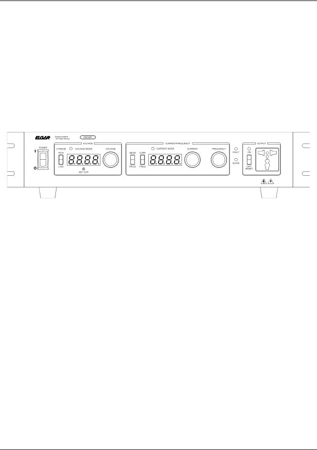
Figure 1-1. ContinuousWave (Model CW1251M) Front Panel
1-2 |
M161570-01 |
SECTION 2
SPECIFICATIONS
Note: Product specifications are subject to change without notice.
2.1OUTPUT
Power
CW 801M: 800 VA
CW 1251M: 1250 VA
CW 2501M: 2500 VA
Power Factor of Load: 0 lag to 0 lead
Phase: All models single phase output
Voltage
Ranges: 0 to 135 VAC RMS or 0 to 270 VAC RMS manual switch (consult factory for custom output voltages)
Accuracy: 1% of range for voltages >5V
Resolution: 0.1V
Total Harmonic Distortion: 0.65% maximum up to 60 Hz; add 0.05%/10 Hz from 60 Hz to 100 Hz; add 0.4%/100 Hz from >100 Hz
AC Noise Level: <50m VRMS typical for CW 801M and CW 1251M, 100m VRMS typical for CW 2501M
Amplitude Stability: ±0.1% of full scale over 8 hours at constant line, load and temperature after 15 minute warm-up
M161570-01 |
2-1 |

Elgar CW-M Series
Load Regulation: ±0.1% of full scale voltage for a full resistive load to no load
Line Regulation: ±0.1% of full scale for a ±10% line change from nominal line voltage
Remote Voltage Sense: 5 VRMS total lead voltage drop
2.2CURRENT
CW 801M: 6.00 ARMS in 135 VAC range or 3.00 ARMS in 270 VAC range
CW 1251M: 9.40 ARMS in 135 VAC range or 4.70 ARMS in 270 VAC range
CW 2501M: 18.60 ARMS in 135 VAC range or 9.30 ARMS in 270 VAC range
Frequency
Range: 45 to 500 Hz
Accuracy: ±0.5% typical
Resolution: 0.1 Hz
2.3MEASUREMENT
Voltage
Range: 0 to 135/270 VRMS
Accuracy: ±1% of range for voltages >5V, measured at point of sense Resolution of Display: 0.1V
Current
Range: 0 to 6.0 ARMS (CW 801M) 0 to 9.4 ARMS (CW 1251M)
0 to 18.6 ARMS (CW 2501M)
Accuracy: ±2% of range for linear loads with current >0.2A for CW 801M and CW 1251M, >0.4A for CW 2501M
Resolution of Display: 0.1A
Frequency
Range: 45 to 500 Hz
Accuracy: ±0.5% of reading
Resolution of display: 0.1 Hz
2-2 |
M161570-01 |

Elgar CW-M Series
2.4FRONT PANEL
Controls
Power On/Off switch
Output On/Off/Reset switch: Operates output isolation relays. Off also resets faults.
Voltage Range switch: Selects 135 Vmax or 270 Vmax range (Output switch must be off to change range)
Meter Select switch: Current/frequency select
Output Voltage: Adjusted using 10–turn potentiometer Output Current: Adjusted using 10–turn potentiometer Output Frequency: Adjusted using 10–turn potentiometer
Overvoltage Protection: Settable 5 to 300 VRMS using a 15–turn screwdriver adjust potentiometer
Displays
Voltage: 4–digit, 7–segment large, green LED display
Current or Frequency: 4–digit, 7–segment large, green LED display
Protection and Isolation
Overvoltage: Set screw adjustable Overcurrent: 10–turn potentiometer
Accuracy: ±2% of range for linear loads with current >0.2 A for CW801M and CW1251M, >0.4A for CW2501M.
Overtemperature: Internal monitor
Isolation Rating: 500V between either output terminal and chassis
Indicators
Output On: Green LED Voltage Mode: Green LED Current Mode: Green LED Slave Mode: Green LED Fault Mode: Red LED
Output Connector
Universal single socket connector for front panel power out on CW 801M and CW 1251M
Line and neutral terminals can be switched through rear connector interconnect
M161570-01 |
2-3 |

Elgar CW-M Series
2.5REAR PANEL CONNECTIONS
Input Connector: Covered barrier terminal strip with strain relief
Output Connector: Covered barrier terminal strip with strain relief
Remote output voltage sense: 5 VRMS max total lead voltage drop
Remote Analog Control:
Output voltage control 0 to 5 VDC
Output frequency control 0 to 5 VDC (max slew rate 5V/second)
Dip Switches (see Section SECTION 4 on page 4-1):
Master or Slave field configuration
Output disable/enable at power-up
Overcurrent shutdown enable/disable
2.6INPUT
Voltage and Frequency
CW 801M: 90 to 264 VAC, 47 to 63 Hz, single-phase CW 1251M: 103 to 264 VAC, 47 to 63 Hz, single-phase CW 2501M: 180 to 264 VAC, 47 to 63 Hz, single-phase
Neutral should be connected to ground at building entrance Max neutral to chassis voltage: 132V RMS
Current
CW 801M: 13 ARMS max CW 1251M: 18.5 ARMS max CW 2501M: 19.5 ARMS max
Power Factor
>0.95 at full load nominal line
Efficiency
>70% at full load
2-4 |
M161570-01 |

Elgar CW-M Series
2.7GENERAL
Dimensions
CW 801M: 3.5" H (89 mm) x 19" W (483 mm) x 20.6" D (524 mm) CW 1251M: 3.5" H (89 mm) x 19" W (483 mm) x 20.6" D (524 mm) CW 2501M: 5.25" H (133 mm) x 19" W (483 mm) x 20.6" D (524 mm)
Weight
CW 801M: 48 lbs. (22 kg)
CW 1251M: 53 lbs. (24 kg)
CW 2501M: 86 lbs. (39 kg)
Shipping Weight
CW 801M: 56 lbs. (25 kg)
CW 1251M: 61 lbs. (28 kg)
CW 2501M: 94 lbs. (43 kg)
Regulatory Compliance
CE mark
LVD: EN61010-1:1993 + Amendment 2
EMC: EN55011:1991 Group 1, Class A, EN50082-1:1992
Environmental
Cooling: Dual fan speed with side air intake, exhaust to rear
Operating Temperature: 0 to 40°C
Storage Temperature: -40 to +70°C
Humidity: 0 to 85% at 25°C derate to 50% above 40°C (non-condensing)
Altitude: Operating full power available up to 6,000 feet, non-operating to 40,000 feet
Installation Category III, Pollution Degree 2
FOR INDOOR USE ONLY
2.8OPTIONS AND ACCESSORIES
L:Locking knobs (front panel potentiometers)
Rack Slide Kit (Elgar part number K161570-01)
Parallel Cable (Elgar part number 890-497-40)
M161570-01 |
2-5 |
 Loading...