


Ametek RTC-125A, RTC-157A, RTC-158A, RTC-159A, RTC-187A Operating Manual
...User Manual
Reference/Professional Temperature Calibrator
Jofra RTC-125/157/158/159/187/250/700 A/B/C
Jofra PTC-125/155/350/425/660 A/B/C

User Manual
Reference/ Professional Temperature Calibrator
JOFRA RTC-156/157/158/159/187/250/700 A/B/C
JOFRA PTC-125/155/350/425/660 A/B/C
Copyright 2012 AMETEK Denmark A/S

2 |
2018-03-13 |
128206 06 |

List of contents
1.0 |
Introduction ............................................................................ |
5 |
||
|
1.1 |
List of equipment received ........................................................ |
6 |
|
2.0 |
Safety instructions ................................................................. |
8 |
||
3.0 Setting up the calibrator ...................................................... |
15 |
|||
|
3.1 |
Before use ............................................................................... |
15 |
|
|
|
3.1.1 |
Setting up a dry-block calibrator .................................... |
18 |
|
|
3.1.2 |
Setting up a liquid bath calibrator (RTC-158/250 only).. |
20 |
|
3.2 |
During use ............................................................................... |
24 |
|
|
3.3 |
Programming intelligent sensors ................................................ |
25 |
|
|
3.4 |
Keyboard..................................................................................... |
25 |
|
|
3.5 |
Main screen display .................................................................... |
27 |
|
|
3.6 |
Standard connections ................................................................. |
31 |
|
|
3.7 |
Input modules (B and C versions only)....................................... |
32 |
|
|
3.8 |
Stability of temperature values ................................................... |
33 |
|
4.0 |
Operating the Calibrator ...................................................... |
34 |
||
|
4.1 |
Operating principle...................................................................... |
34 |
|
|
|
4.1.1 |
Horizontal Menu............................................................. |
35 |
|
|
4.1.2 |
Vertical Menu ................................................................. |
35 |
|
|
4.4.3 |
Parameter Fields............................................................ |
36 |
|
|
4.4.4 |
Working with lists ........................................................... |
38 |
|
4.5 |
Starting the calibrator.................................................................. |
40 |
|
|
4.6 |
Setting the temperature .............................................................. |
40 |
|
|
4.7 |
Calibration (optional - PTC) ........................................................ |
41 |
|
|
|
4.7.1 |
Running a calibration ..................................................... |
42 |
|
|
4.7.2 |
Viewing calibration results ............................................. |
46 |
|
|
4.7.3 |
Displaying calibration information .................................. |
47 |
|
|
4.7.4 |
Deleting workorders ....................................................... |
49 |
|
4.8 |
Switch test menu ........................................................................ |
50 |
|
|
|
4.8.1 |
Running a switch test..................................................... |
50 |
|
|
4.8.2 |
Showing switch test results............................................ |
52 |
|
4.9 |
Auto step menu........................................................................... |
54 |
|
|
|
4.9.1 |
Running an Auto step calibration ................................... |
54 |
|
|
4.9.2 |
Auto Step test results..................................................... |
57 |
|
4.10 Sensor Setup menu .................................................................... |
58 |
||
|
|
4.10.1 |
Setting the additional stability time (A version) .............. |
58 |
|
|
4.10.2 |
Setting the parameters for TRUE – reference sensor (B |
|
|
|
|
and C versions only) ...................................................... |
59 |
|
|
4.10.3 |
Setting the parameters for DLC– dynamic load |
|
128206 |
06 |
2018-03-13 |
3 |
|

|
compensation – (RTC, B and C versions only).............. |
61 |
4.10.4 Setting the parameters for SUT– Sensor under test (B |
|
|
|
versions only) ................................................................. |
61 |
4.10.5 Viewing the Reference and DLC data (B and C versions |
||
|
only) ............................................................................... |
64 |
4.11 Calibrator Setup menu................................................................ |
65 |
|
4.11.1 Setting the temperature parameters .............................. |
65 |
|
4.11.2 Setting the temperature resolution................................. |
67 |
|
4.11.3 Setting the sound, volume and operating mode ............ |
68 |
|
4.11.4 |
Setting calibration interval.............................................. |
68 |
4.11.5 Changing the date and time........................................... |
68 |
|
4.11.6 Choosing a language (optional) ..................................... |
69 |
|
4.11.7 |
Saving a setup ............................................................... |
69 |
4.11.8 |
Loading a setup ............................................................. |
70 |
4.11.9 Resetting the instrument setup to factory defaults......... |
70 |
|
4.11.10 Network Configuration (for service use only)................. |
71 |
|
4.12 Selecting the stirrer speed (RTC-158/250 only) ........................ |
72 |
|
4.13 Information Screen ..................................................................... |
73 |
|
4.14 About the calibrator..................................................................... |
74 |
|
5.0 Setting the mains voltage and replacing the main fuses... |
75 |
|
6.0 After use................................................................................ |
|
77 |
6.1 Storing and transporting the calibrators...................................... |
77 |
|
6.2 Handling the dry-block calibrator ................................................ |
78 |
|
6.3 Handling the liquid-bath calibrator (RTC158/250 only) ............ |
79 |
|
4 |
2018-03-13 |
128206 06 |

1.0Introduction
This user manual applies to the following instruments:
Reference Temperature Calibrators
∙JOFRA RTC-156 A - Temperature calibrator
∙JOFRA RTC-156 B - Temperature calibrator with sensor and
reference inputs
∙JOFRA RTC-156 C - Temperature calibrator with reference input
∙JOFRA RTC-157 A - Temperature calibrator
∙JOFRA RTC-157 B - Temperature calibrator with sensor and
reference inputs
∙JOFRA RTC-157 C - Temperature calibrator with reference input
∙JOFRA RTC-158 A - Temperature calibrator
∙JOFRA RTC-158 B - Temperature calibrator with sensor and
reference inputs
∙JOFRA RTC-158 C - Temperature calibrator with reference input
∙JOFRA RTC-159 A – Temperature calibrator
∙JOFRA RTC-159 B – Temperature calibrator with sensor and
reference inputs
∙JOFRA RTC-159 C - Temperature calibrator with reference input
∙JOFRA RTC-187 A - Temperature calibrator
∙JOFRA RTC-187 B - Temperature calibrator with sensor and
reference inputs
∙JOFRA RTC-187 C - Temperature calibrator with reference input
∙JOFRA RTC-250 A - Temperature calibrator
∙JOFRA RTC-250 B - Temperature calibrator with sensor and
reference inputs
∙JOFRA RTC-250 C - Temperature calibrator with reference input
∙JOFRA RTC-700 A - Temperature calibrator
∙JOFRA RTC-700 B - Temperature calibrator with sensor and
reference inputs
∙JOFRA RTC-700 C - Temperature calibrator with reference input
Professional Temperature Calibrators
∙JOFRA PTC-125 A - Temperature calibrator
∙JOFRA PTC-125 B - Temperature calibrator with sensor and
reference inputs
∙JOFRA PTC-125 C - Temperature calibrator with reference input
∙JOFRA PTC-155 A - Temperature calibrator
128206 06 |
2018-03-13 |
5 |

∙JOFRA PTC-155 B - Temperature calibrator with sensor and
reference inputs
∙JOFRA PTC-155 C - Temperature calibrator with reference input
∙JOFRA PTC-350 A - Temperature calibrator
∙JOFRA PTC-350 B - Temperature calibrator with sensor and
reference inputs
∙JOFRA PTC-350 C - Temperature calibrator with reference input
∙JOFRA PTC-425 A – Temperature calibrator
∙JOFRA PTC-425 B – Temperature calibrator with sensor and
reference inputs
∙JOFRA PTC-425 C - Temperature calibrator with reference input
∙JOFRA PTC-660 A - Temperature calibrator
∙JOFRA PTC-660 B - Temperature calibrator with sensor and
reference inputs
∙JOFRA PTC-660 C - Temperature calibrator with reference input
These instruments are temperature calibrators designed to calibrate temperature sensors and thermostats.
The RTC-156/157/159/187/700 A/B/C instruments and the PTC-series are all designed as dry-block calibrators, where as the RTC-158/250 A/B/C instruments are designed to be used both as dry-block calibrators and liquid baths.
Read this manual carefully before using the instrument and ensure that all safety instructions and warnings are observed.
1.1List of equipment received
When you receive the instrument, the following should be enclosed:
∙1 calibrator
∙1 mains cable
∙2 sets of test cables (2 black, 2 red –B versions only)
∙1 software package “JOFRACAL” and reference manual
∙1 USB cable
∙1 tool for insertion tube
∙1 traceable certificate (A versions)
∙2 traceable certificates (C versions)
∙3 traceable certificates (B versions)
6 |
2018-03-13 |
128206 06 |

∙1 set of silicone plugs for insulation plugs (RTC156/157/158/159/187/250 and PTC-125/155 only)
∙1 insulation collar (RTC-156 only)
∙1 protection shield (RTC-700 and PTC-660 only)
Caution
Do not use the RTC-158 insulation plug (black POM) with the RTC-250 instrument due to the risk of melting.
Always use the correct - yellow/brown PEEK - insulation plug with the RTC-250 instrument.
RTC-158/250 A/B/C only (liquid bath) - OPTIONAL
∙1 liquid bath kit consisting of :
-1 sensor basket
-2 lids for transportation / calibration
-1 stirring magnet
-1 stirring magnet remover
-1 liquid drainage syringe
-1 bottom shield
-1 silicone oil
-1 oil material safety data sheet
128206 06 |
2018-03-13 |
7 |
2.0Safety instructions
Read this manual carefully before using the instrument!
In order to avoid any personal injuries and/or damage to the instrument all safety instructions and warnings must be observed.
The screen menus shown in this manual represent the menus displayed when using a B-version.
Disposal – WEEE Directive
These calibrators contain Electrical and Electronic circuits and must be recycled or disposed of properly (in accordance with the WEEE Directive 2012/19/EU).
Warning
About the use:
∙The calibrator must not be used for any purposes other than those described in this manual, as it might cause a hazard.
∙The calibrator has been designed for indoor use only and is not to be used in wet locations.
∙The calibrator is not to be used in hazardous areas, where vapour or gas leaks, etc. may constitute a danger of explosion.
∙The calibrator is not designed for operation in altitudes above 2000 meters.
∙The calibrator is a CLASS I product and must be connected to a mains outlet with a protective earth connection. Ensure the ground connection of the calibrator is properly connected to the protective earth before switching on the calibrator. Always use a mains power cable with a mains plug that connects to the protective earth.
8 |
2018-03-13 |
128206 06 |

∙To ensure the connection to protective earth any extension cord used must also have a protective earth conductor.
∙Only use a mains power cord with a current rating as specified by the calibrator and which is approved for the voltage and plug configuration in your area.
∙Before switching on the calibrator make sure that it is set to the voltage of the mains electricity supply.
∙Always position the calibrator to enable easy and quick disconnection of the power source (mains inlet socket).
∙The calibrator must be kept free within an area of 20 cm on all sides and 1 metre above the calibrator due to fire hazard.
∙After transport or storage in humid conditions or if the calibrator has not been heated up to minimum 100°C within the last 10 days, the instrument needs to be operated with a well temperature of at least 140°C for 2 hours before it can be assumed to meet all safety requirements of EN61010-1 (PTC-350/425/660 and RTC-250/700 only).
∙If the calibrator is wet or has been in a wet environment, do not apply power until the moisture has been removed for example by storage at 50°C in a low humidity environment for at least 4 hours.
∙Never use heat transfer fluids such as silicone, oil, paste, etc. in the dry-block calibrators. These fluids may penetrate the calibrator and cause electrical hazard, damage or create poisonous fumes.
∙The calibrator must be switched off before any attempt to service the instrument is made. There are no user serviceable parts inside the calibrator.
∙When cleaning the well or the insertion tube, REMEMBER to wear goggles when using compressed air in the dry-block calibrator and cleaning oil in the liquid bath calibrator.
∙Use protection shield when calibrating at high temperatures (RTC-700 and PTC-660)
128206 06 |
2018-03-13 |
9 |
∙The RTC-159 and PTC-125 contains R-1270 and R- 704 under pressure. The calibrator must under no conditions be stored at ambient temperatures above
50°C ( 122°F) or operated at ambient temperatures above 40°C (104°F). Doing so may cause a hazard.
About the front panel:
∙For B and C versions only, the sockets on the input module must NEVER be connected to voltages exceeding 30V with reference to ground.
∙Thermostats must not be connected to any other voltage sources during test.
About insertion tubes, insulation plugs, well and sensor:
∙Never leave hot insertion tubes which have been removed from the calibrator unsupervised – they may constitute a fire hazard or personal injury.
If you intend to store the calibrator in the optional carrying case after use, you must ensure that the instrument has cooled down to a temperature below 100°C/212°F before placing it in the carrying case.
∙Never place a hot insertion tube in the optional carrying case.
About the fuses:
∙The fuse box must not be removed from the power control switch until the mains cable has been disconnected.
∙The two main fuses must have the specified current and voltage rating and be of the specified type. The use of makeshift fuses and the short-circuiting of fuse holders are prohibited and may cause a hazard.
About the liquid bath (RTC-158/250 A/B/C only):
∙For liquid bath ensure that the sensor is absolutely clean and dry as a few drops of water in the well (liquid baths) might cause a steam explosion.
10 |
2018-03-13 |
128206 06 |

∙Do not pour cold fluid into a hot well – it might cause an explosion.
∙AMETEK Denmark A/S does not take any responsibility, if the well is filled with other fluids than those recommended.
∙Liquid baths should only be operated by trained personal.
∙Heat transfer fluids must only be used in calibrators prepared as a liquid bath. If these fluids are heated above specified temperature they will create noxious or toxic fumes. Proper ventilation must be used.
∙To avoid hazards from treating fluids in a wrong manner, always reduce the "Max. SET-temperature allowed” in the CALIBRATOR SETUP MENU according to the specifications of the fluid to be used.
If using a calibrator outside of the fluids specifications there is a risk of fire hazards, personal Injury or chemical release.
By reducing the "Max. SET-temperature allowed”, the calibrator cannot be used outside this temperature range.
Be aware of the flash point, the boiling point and other fluid properties applicable to the usage when setting the Max. SET-temperature. Read the MSDS (Material Safety Data Sheet) of the liquid before use.
∙Always remove the liquid from the calibrator before transportation.
∙Product information on the fluid must be carefully investigated before use.
∙Do not handle hot fluid.
∙If the oil is heated beyond the flash point, it may constitute a fire hazard.
∙Do not pour water or any other fluids into a bath filled with hot oil, because only a few drops of water might cause a steam explosion, if poured into above 100°C hot oil.
∙Do not under any circumstances pour water on burning oil. It might cause a dangerous steam explosion.
128206 06 |
2018-03-13 |
11 |

Caution – Hot surface
This symbol is engraved in the grid plate.
∙Do not touch the grid plate, the well or the insertion tube when the calibrator is heating up – they may be very hot and cause burns.
∙Do not touch the lid or the spill tray when the calibrator is heating up – they may be very hot and cause burns (RTC-158/250 A/B/C only).
∙Do not touch the tip of the sensor when it is removed from the insertion tube/well – it may be very hot and cause burns.
∙Do not touch the handle of the calibrator during use – it may be very hot and cause burns.
∙Over 50°C/122°F
If the calibrator has been heated up to temperatures above 50°C/122°F, you must wait until the instrument reaches a temperature below 50°C/122°F before you switch it off.
∙Do not remove the insert from the calibrator before the insert has cooled down to less than 50°C/122°F.
Caution – Cold surface
Below 0°C/32°F
(applies only to the RTC-156/157/158/159/187 A/B/C and PTC-125/155 A/B/C models)
∙Do not touch the well or insertion tube when these are below 0°C/32°F - they might create frostbite.
∙If the calibrator has reached a temperature below 0°C/32°F, ice crystals may form on the insertion tube and on the well. This, in turn, may cause the material surfaces to oxidize.
To prevent this from happening, the insertion tube and the well must be dried. This is done by heating up the calibrator to min. 100°C/212°F until all water left has evaporated.
Remove the insulation plug while heating up.
12 |
2018-03-13 |
128206 06 |

∙It is very important that humidity in the well and insertion tube is removed to prevent corrosion and frost expansion damages.
Caution…
About the use:
∙Do not use the instrument if the internal fan is out of order.
∙Before cleaning the calibrator, you must switch it off, allow it to cool down and remove all cables.
About the liquid bath (RTC-158/250 A/B/C only):
∙Be careful not to overfill the well with oil.
∙Avoid getting silicone oil on the clothes. It is impossible to wash off.
∙The oil level rises several centimetres when the temperature is rising. Please read instructions in section 3.1.2 about oil level. To stop overflow switch off the main power and the oil level will decrease when cooled down.
∙Carefully wipe off all silicone oil from the sensor under test to avoid spreading of the silicone oil.
∙Be careful to select the right oil for the right task. Using other than the recommended oils might cause damage to the calibrator or degrade the performance.
∙Remove excess hot fluid with the outmost care, as it might be very hot.
∙Do not attempt to remove hot fluid with the liquid drainage tube, as it might melt.
About the well, insertion tube and sensor:
∙The well and the insertion tube must be clean and dry before use.
∙Do not pour any form of liquids into the well. It might damage the well or cause a hazard.
∙Do not use any alkali, acid or ionic fluids in the aluminium well as it might be damaged.
128206 06 |
2018-03-13 |
13 |

∙Scratches and other damage to the insertion tubes should be avoided by storing the insertion tubes carefully when not in use.
∙The insertion tube must never be forced into the well.
The well could be damaged as a result, and the insertion tube may get stuck.
∙Before using new insertion tubes for the calibration, the insertion tubes must be heated up to maximum temperature – 250°C (482°F) / 700°C (1292°F) (RTC250/700 A/B/C only) and 350°C (662°F) / 425°C
(797°F) / 660°C (1220°F) (PTC-350/660 A/B/C only) - for a period of minimum 30 minutes.
∙The insertion tube must always be removed from the calibrator after use.
The humidity in the air may cause corrosion oxidation on the insertion tube inside the instrument. There is a risk that the insertion tube may get stuck if this is allowed to happen.
∙If the calibrator is to be transported, the insertion tube must be removed from the well to avoid damage to the instrument.
∙The tip of the sensor should rest at the bottom of the sensor basket for optimum results (liquid baths only).
∙Be careful not to submerge the handle or wire inlet of the sensor-under-test in the fluid, as this might damage the sensor (liquid baths only).
Note…
The product liability only applies if the instrument is subject to a manufacturing defect. This liability becomes void if the user fails to follow the instructions set out in this manual or uses unauthorized spare parts.
14 |
2018-03-13 |
128206 06 |

3.0Setting up the calibrator
3.1Before use
The RTC/PTC-B-versions have a precision reference input. To achieve the high precision, a set of sensor coefficients relating to the specific sensor must be present in the RTC/PTC. Before use of the RTC/PTC, ensure that the correct coefficients in the RTC/PTC are equal to those from the sensors calibration certificate. This is done with the included PC software JOFRACAL. Please read how to do in the chapter “Reference Sensors” in the JOFRACAL user manual.
Warning
∙ The calibrator must not be used for any purposes other than those described in this manual, as it might cause a hazard.
∙The calibrator has been designed for indoor use only and is not to be used in wet locations.
∙The calibrator is not to be used in hazardous areas, where vapour or gas leaks, etc. may constitute a danger of explosion.
∙The calibrator is not designed for operation in altitudes above 2000 meters.
∙The calibrator is a CLASS I product and must be connected to a mains outlet with a protective earth connection. Ensure the ground connection of the calibrator is properly connected to the protective earth before switching on the calibrator. Always use a mains power cable with a mains plug that connects to the protective earth.
∙To ensure the connection to protective earth any extension cord used must also have a protective earth conductor.
∙Only use a mains power cord with a current rating as specified by the calibrator and which is approved for the voltage and plug configuration in your area.
128206 06 |
2018-03-13 |
15 |

∙Before switching on the calibrator make sure that it is set to the voltage of the mains electricity supply.
∙Always position the calibrator to enable easy and quick disconnection of the power source (mains inlet socket).
∙The calibrator must be kept free within an area of 20 cm on all sides and 1 metre above the calibrator due to fire hazard.
∙Never use heat transfer fluids such as silicone, oil, paste, etc. in the dry-block calibrators. These fluids may penetrate the calibrator and cause electrical hazard, damage or create poisonous fumes.
∙Use protection shield when calibrating at high temperatures (RTC-700 and PTC-660)
∙The RTC-159 and PTC-125 contains R-1270 and R-704 under pressure. The calibrator must under no conditions be stored at ambient temperatures above
50°C ( 122°F) or operated at ambient temperatures above 40°C (104°F). Doing so may cause a hazard.
About the front panel:
∙For B and C versions only, the sockets on the input module must NEVER be connected to voltages exceeding 30V with reference to ground. Thermostats must not be connected to any other voltage sources during test.
About the liquid bath (RTC-158/250 A/B/C only):
∙For liquid bath ensure that the sensor is absolutely clean and dry as a few drops of water in the well (liquid baths) might cause a steam explosion.
∙Do not pour cold fluid into a hot well – it might cause an explosion.
∙AMETEK Denmark A/S does not take any responsibility, if the well is filled with other fluids than those recommended.
∙Liquid baths should only be operated by trained personal.
∙Heat transfer fluids must only be used in calibrators prepared as a liquid bath. If these fluids are heated
16 |
2018-03-13 |
128206 06 |

above specified temperature they will create noxious or toxic fumes. Proper ventilation must be used.
∙To avoid hazards from treating fluids in a wrong manner, always reduce the "Max. SET-temperature allowed” in the CALIBRATOR SETUP MENU according to the specifications of the fluid to be used.
If using a calibrator outside of the fluids specifications there is a risk of fire hazards, personal Injury or chemical release.
By reducing the "Max. SET-temperature allowed”, the
calibrator cannot be used outside this temperature range.
Be aware of the flash point, the boiling point and other fluid properties applicable to the usage when setting the Max. SET-temperature. Read the MSDS (Material Safety Data Sheet) of the liquid before use. The Max. SET-temperature must never exceed (liquid flash point – 50°C).
∙Product information on the fluid must be carefully investigated before use.
∙Do not handle hot fluid.
∙If the oil is heated beyond the flash point, it may constitute a fire hazard.
∙Do not pour water or any other fluids into a bath filled with hot oil, because only a few drops of water might cause a steam explosion, if poured into above 100°C hot oil.
∙Do not under any circumstances pour water on burning oil. It might cause a dangerous steam explosion.
Note…
The instrument must not be exposed to draughts.
128206 06 |
2018-03-13 |
17 |
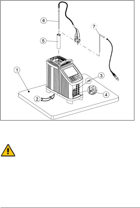
3.1.1Setting up a dry-block calibrator
Fig. 1a – This image shows the RTC-model
Follow the instructions below before using the calibrator (cf. fig. 1a)
Warning
Always position the calibrator to enable easy and quick disconnection of the power source (mains inlet socket).
1.Place the calibrator on an even horizontal surface where you intend to use it (pos. 1).
18 |
2018-03-13 |
128206 06 |

Caution…
∙Do not use the instrument if the internal fan is out of order.
∙The well must be clean before use.
2.Ensure a free supply of air to the internal fan located at the bottom of the instrument (pos. 2)
The area around the calibrator should be free of draught, dirt, flammable substances, etc.
3.Check that the voltage setting, shown on the power control switch (pos. 3), is identical to the mains voltage used.
4.Check that the earth connection for the instrument is present and attach the cable below the power control switch (pos. 4).
5.Select an insertion tube (pos. 5) with a boring diameter matching the sensor (pos. 6) to be calibrated. Ensure that both the well and the insertion tube are clean. Insert the tube into the well.
6.Place the sensor (pos. 6) and the reference sensor – if available (pos. 7) in the insertion tube (pos. 5) as shown in fig. 1a.
128206 06 |
2018-03-13 |
19 |

3.1.2Setting up a liquid bath calibrator (RTC-158/250 only)
10 |
11 |
9
Oil
6 
5 

4 

3
1 |
7 |
|


 8 2
8 2 


Fig. 1b
Follow the instructions below before using the calibrator (cf. fig. 1b)
Warning
Always position the calibrator to enable easy and quick disconnection of the power source (mains inlet socket).
1.Place the calibrator on an even horizontal surface where you intend to use it. Place it in a way that will minimize the risk of tilting (pos. 1). It is recommended to cover the surface with a disposable cover in order to protect the surface against the silicone oil, if spilled.
20 |
2018-03-13 |
128206 06 |

It is also recommendable to have a sufficient amount of disposable paper towels within reach.
Caution…
∙Do not use the instrument if the internal fan is out of order. Ensure a free supply of air to the internal fan located at the bottom of the instrument (pos. 2).
∙The well must be clean before use.
2.The area around the calibrator should be free of draught, dirt, flammable substances, etc.
3.Place the parts from the liquid bath kit in the well in the following order:
∙Bottom shield (pos. 3) – It is very important that the bottom shield is placed in the well before any calibration is attempted, as the bottom shield protects the well from being damaged during calibration.
∙Stirring magnet (pos. 4) – It is very important that the stirring magnet is in place and spinning before any calibration is attempted. The stirring magnet ensures minimum temperature gradient in the fluid. The magnets teflon cover will over time be worn down, leaving the magnet flat on one side. This will reduce the spinning ability. A magnet with a flat side must therefore be replaced.
∙Sensor basket (pos. 5) – It is very important to place the sensor basket in the well, as it ensures that the sensors encounter maximum temperature stability and ensures that the stirring magnet is not blocked.
∙Silicone oil (pos. 6) – Fill the well with oil according to the tables of recommended oil volume listed in the tables below. The recommended volumes must be adjusted to the actual job.
The sensor basket (pos. 4) is marked with an optimum fluid level mark (100%). When filling the well with fluid and placing the sensors, this mark must never be exceeded.
128206 06 |
2018-03-13 |
21 |
RTC-250 A/B/C For recommended
50 cSt oil
0°C - 50°C |
100% |
50°C - 100°C |
95% |
100°C - 150°C |
90% |
150°C - 200°C |
85% |
200°C - 250°C |
80% |
RTC-158 A/B/C For recommended 10 cSt oil
-20°C - 50°C |
100% |
50°C - 100°C |
95% |
100°C - 120°C |
90% |
120°C - 155°C |
85% |
Warning
∙Do not handle hot fluid.
∙Do not pour cold fluid into a hot well – it might cause an explosion
∙Do not pour water or any other fluids into a bath filled with hot oil, because only a few drops of water might cause a steam explosion, if poured into e.g. above 100°C hot oil.
∙If the fluid is heated beyond the flash point, it may constitute a fire hazard.
∙AMETEK Denmark A/S does not take any responsibility, if the well is filled with other fluids than those recommended.
If the fluid has caught fire, switch off the main power to prevent further heating of the fluid. Flames are best extinguished by cowering the well with a non-flammable lid.
Caution…
∙Be careful not to overfill the well with oil.
The oil level rises several centimetres when the temperature is rising to maximum. To stop the overflow switch off the main power and the oil level will decent.
∙Do not attempt to remove hot fluid with the liquid drainage syringe, as it might melt.
4.Check that the voltage setting, shown on the power control switch (pos. 7), is identical to the mains voltage used.
22 |
2018-03-13 |
128206 06 |
5.Plug in the mains cable below the power control switch (pos. 8) and check that the earth connection is present. Switch on the calibrator.
6.Start the stirring magnet by following the procedure in section 4.12.
Warning
Always set the “Max. SET-temperature” of the calibrator according to the specified temperature range of the liquid. The “Max. SET-temperature” must never exceed the flash point or the boiling point of the liquid.
7.Select a SET-temperature according to the tables of recommended oil volume by following the procedure in section 4.6.
8.Carefully monitor the oil level in the well, as the temperature rises, to prevent overflow.
9.Place the calibration lid (pos. 9) onto the well. Holes with a boring diameter matching the sensors to be calibrated must be drilled into the lid before using it.
10.Place the sensor (pos. 10) and the reference sensor – if available (pos. 11) - to be calibrated vertically into the well. It is recommended to use the optional support rod set for a correct position during calibration.
Caution…
∙The tip of the sensor should rest at the bottom of the sensor basket for optimum results.
∙Be careful not to submerge the handle or wire inlet of the sensor-under-test in the fluid, as this might damage the sensor.
Start the calibration of either the dry-block calibrator or the liquid bath calibrator following the calibration procedure in this manual.
128206 06 |
2018-03-13 |
23 |
3.2During use
Caution – Hot surface
This symbol is engraved in the grid plate. 


∙Do not touch the grid plate, the well or the insertion tube while the calibrator is heating up – they may be very hot and cause burns.
∙Do not touch the lid or the spill tray when the calibrator is heating up – they may be very hot and cause burns (liquid baths only).
∙Do not touch the tip of the sensor when it is removed from the insertion tube – it may be very hot and cause burns.
∙Do not touch the handle of the calibrator during use – it may be very hot and cause burns.
∙Do not remove the insert from the calibrator before the insert has cooled down to less than 50°C/122°F.
Caution – Cold surface
∙If the calibrator has reached a temperature below 0°C/32°F, ice crystals may form on the insertion tube and on the well. This, in turn, may cause the material
surfaces to oxidize.
To prevent this from happening, the insertion tube and the well must be dried. This is done by heating up the calibrator to min. 100°C/212°F until all water left has evaporated.
Remove the insulation plug while heating up.
It is very important that humidity in the well and insertion tube is removed to prevent corrosion and frost expansion damages.
∙Do not touch the well or insertion tube when these are below 0°C/32°F – they might create frostbite.
Caution…(liquid baths only)
∙ Be careful to select the right fluid for the right task. Using other than the recommended fluids might cause damage to the calibrator or degrade the performance.
24 |
2018-03-13 |
128206 06 |
 Loading...