


Ametek CTC-155A, CTC-350A, CTC-652A, CTC-660A, CTC-155C Operating Manual
...Reference Manual
Compact Temperature Calibrator
Jofra CTC-155/350/660 A/C
Reference Manual
Compact Temperature Calibrator
JOFRA CTC-155/350/660 A/C
Copyright 2016 AMETEK Denmark A/S

About this manual….
The structure of the manual
This reference manual is aimed at users who are familiar with AMETEK calibrators, as well as those who are not. The manual is divided into 11 sections which describe how to set up, operate, service and maintain the calibrator. The technical specifications are described and accessories may be ordered from the list of accessories.
Safety symbols
This manual contains a number of safety symbols designed to draw your attention to instructions which must be followed when using the instrument, as well as any risks involved.
Warning
Conditions and actions that may compromise the safe use of the instrument and result in considerable personal or material damage.
Caution…
Conditions and actions that may compromise the safe use of the instrument and result in slight personal or material damage.
Note…
Special situations which demand the user’s attention.
129375 00 |
2016-05-18 |
2 |

List of contents
1.0 |
Introduction ................................................................................................................................. |
4 |
||
|
1.1 |
Warranty................................................................................................................................................ |
5 |
|
|
1.2 |
Receiving the Compact Temperature Calibrator................................................................................... |
6 |
|
|
1.3 |
Dimensioning drawing........................................................................................................................... |
7 |
|
2.0 |
Safety instructions...................................................................................................................... |
8 |
||
3.0 |
Setting up the calibrator for use.............................................................................................. |
11 |
||
|
3.1 |
Preparing the calibrator....................................................................................................................... |
11 |
|
|
3.2 |
Choosing an insertion tube ................................................................................................................. |
12 |
|
|
|
3.2.1 |
Standard insertion tubes ........................................................................................................ |
13 |
|
3.3 |
Inserting the sensor............................................................................................................................. |
14 |
|
|
3.4 |
Programming intelligent STS sensors................................................................................................. |
16 |
|
4.0 |
Calibrator Interface ................................................................................................................... |
17 |
||
|
4.1 |
Keypad - Functions ............................................................................................................................. |
17 |
|
|
4.2 |
Display - Functions.............................................................................................................................. |
17 |
|
|
|
4.2.1 Main screen temperature values ............................................................................................ |
18 |
|
|
|
4.2.2 Stability of temperature values ............................................................................................... |
18 |
|
|
4.3 |
Input/Output Connections ................................................................................................................... |
19 |
|
5.0 |
Operating the calibrator ........................................................................................................... |
20 |
||
|
5.1 |
Operating principle .............................................................................................................................. |
20 |
|
|
|
5.1.1 |
System menu.......................................................................................................................... |
21 |
|
5.2 |
Starting the calibrator .......................................................................................................................... |
23 |
|
|
5.3 |
Selecting a TRUE – reference sensor (C-models only) ...................................................................... |
23 |
|
|
5.4 |
Stability setting .................................................................................................................................... |
25 |
|
|
5.5 |
Selecting the set-temperature ............................................................................................................. |
25 |
|
|
|
5.5.1 Editing the preset set-temperature......................................................................................... |
26 |
|
|
5.6 |
Auto Step function............................................................................................................................... |
28 |
|
|
|
5.6.1 Running an Auto Step test ..................................................................................................... |
28 |
|
|
|
5.6.2 The calibrator's Auto Step procedure..................................................................................... |
29 |
|
|
5.7 |
Switch Test function ............................................................................................................................ |
31 |
|
|
|
5.7.1 Running a Switch Test ........................................................................................................... |
31 |
|
|
|
5.7.2 The calibrator's Switch Test procedure .................................................................................. |
33 |
|
6.0 |
Storing and transporting the calibrator .................................................................................. |
34 |
||
7.0 |
Error messages (List of alarms) .............................................................................................. |
37 |
||
8.0 |
Returning the calibrator for service ........................................................................................ |
40 |
||
9.0 |
Maintenance .............................................................................................................................. |
42 |
||
|
9.1 |
Replacing the main fuses.................................................................................................................... |
42 |
|
|
9.2 |
Maintenance mode.............................................................................................................................. |
43 |
|
|
9.3 |
Cleaning .............................................................................................................................................. |
47 |
|
|
9.4 |
Adjusting and calibrating the instrument ............................................................................................. |
48 |
|
|
9.5 |
Maintenance of STS-reference sensor ............................................................................................... |
48 |
|
10.0 |
Technical specifications.......................................................................................................... |
49 |
||
11.0 |
List of accessories.................................................................................................................... |
56 |
||
129375 00 |
2016-05-18 |
3 |

1.0Introduction
Congratulations on your new AMETEK JOFRA CTC Calibrator!
With the AMETEK JOFRA Compact Temperature Calibrator, you have chosen an extremely effective instrument which we hope will live up to all your expectations.
This CTC calibrator is a fast, timesaving, and reliable true industrial temperature calibrator designed for on-site use.
During the past several years, we have acquired extensive knowledge of industrial temperature calibration. This expertise is reflected in our products which are all designed for daily use in an industrial environment. Please note that we would be very interested in hearing from you if you have any ideas or suggestions for changes to our products.
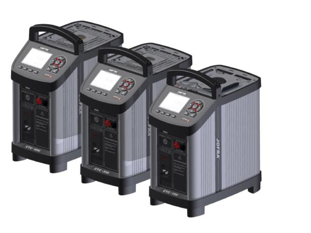
This reference manual applies to the following instruments:
JOFRA CTC-155 A – Temperature calibrator
JOFRA CTC-155 C – Temperature calibrator with reference sensor input
JOFRA CTC-350 A – Temperature calibrator
JOFRA CTC-350 C – Temperature calibrator with reference sensor input
JOFRA CTC-660 A – Temperature calibrator
JOFRA CTC-660 C – Temperature calibrator with reference sensor input
The calibrator has the following features and functions:
Wide temperature range
Fast heating and cooling time as well as a short stabilization time
Signal input for external reference sensor, which makes it possible to improve accuracy even more.
External sensor control for running in two modes.
Multi-Information colour Display and Function keys
Useful features such as Set function, Preset mode, Auto Switch Test and Auto Stepping
IRI – Intelligent Recalibration Information
Plug and play STS reference sensors with memory chip
Broad range of inserts
Reference sensor protection
Silent mode operation
JOFRACAL calibration software
Protective carrying case with compartments for inserts, cables, manuals, plugs etc.
ISO-9001 certified
AMETEK Denmark A/S was ISO-9001 certified in September 1994 by Bureau Veritas Certification Denmark.
129375 00 |
2016-05-18 |
4 |

CE-label
Your new temperature calibrator bears the CE label and conforms to the
Electromagnetic Compatibility (EMC) Directive and the Low Voltage Directive.
Technical assistance
Please contact the dealer from whom you acquired the instrument if you require technical assistance.
1.1Warranty
This instrument is warranted against defects in workmanship, material and design for two (2) years from date of delivery to the extent that AMETEK will, at its sole option, repair or replace the instrument or any part thereof which is defective, provided, however, that this warranty shall not apply to instruments subjected to tampering or, abuse, or exposed to highly corrosive conditions.
THIS WARRANTY IS IN LIEU OF ALL OTHER WARRANTIES WHETHER EXPRESS OR IMPLIED AND AMETEK HEREBY DISCLAIMS ALL OTHER WARRANTIES, INCLUDING,
WITHOUT LIMITATION, ANY WARRANTY OF FITNESS FOR A PARTICULAR PURPOSE OR
MERCHANTABILITY. AMETEK SHALL NOT BE LIABLE FOR ANY INCIDENTAL OR CONSEQUENTIAL DAMAGES, INCLUDING, BUT NOT LIMITED TO, ANY ANTICIPATED OR
LOST PROFITS.
This warranty is voidable if the purchaser fails to follow any and all instructions, warnings or cautions in the instrument’s User Manual.
If a manufacturing defect is found, AMETEK will replace or repair the instrument or replace any defective part thereof without charge; however, AMETEK’s obligation hereunder does not include the cost of transportation, which must be borne by the customer. AMETEK assumes no responsibility for damage in transit, and any claims for such damage should be presented to the carrier by the purchaser.
129375 00 |
2016-05-18 |
5 |

1.2Receiving the Compact Temperature Calibrator
When you receive the instrument…
1)Unpack and check the calibrator and the accessories carefully.
2)Check the parts according to the list shown below.
If any of the parts are missing or damaged, please contact the dealer who sold you the calibrator.
You should receive:
1 CTC Calibrator
1 USB memory stick containing electronic Reference manual and software package JOFRACAL
1 mains cable
1 sets of test leads and test clips (black and red)
Thermal protection shield (CTC-660 only)
1 tool for insertion tube
1 USB cable
1 Calibration certificate (International traceable)
When reordering, please specify the part numbers according to the list of accessories, section 11.0
129375 00 |
2016-05-18 |
6 |
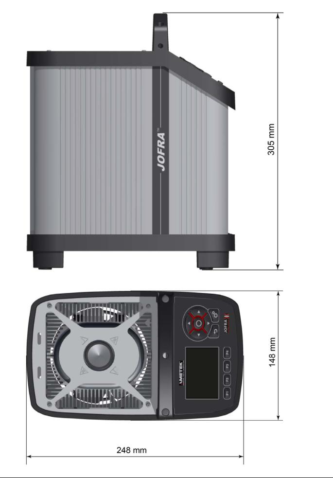
1.3Dimensioning drawing
129375 00 |
2016-05-18 |
7 |

2.0Safety instructions
Read this manual carefully before using the instrument!
Please follow the instructions and procedures described in this manual. They are designed to allow you to get the most out of your calibrator and avoid any personal injuries and/or damage to the instrument.
Disposal – WEEE Directive
These calibrators contain Electrical and Electronic circuits and must be recycled or disposed of properly (in accordance with the WEEE Directive 2002/96/EC).
Warning
About the use:
The calibrator must not be used for any purposes other than those described in this manual, as it might cause a hazard.
The calibrator has been designed for indoor use only and is not to be used in wet locations.
The calibrator is not to be used in hazardous areas, where vapour or gas leaks, etc. may constitute a danger of explosion.
The calibrator is not designed for operation in altitudes above 2000 meters.
The calibrator is a CLASS I product and must be connected to a mains outlet with a protective earth connection. Ensure the ground connection of the calibrator is properly connected to the protective earth before switching on the calibrator. Always use a mains power cable with a mains plug that connects to the protective earth.
To ensure the connection to protective earth any extension cord used must also have a protective earth conductor.
Only use a mains power cord with a current rating as specified by the calibrator and which is approved for the voltage and plug configuration in your area.
Before switching on the calibrator make sure that it is set to the voltage of the mains electricity supply.
Always position the calibrator to enable easy and quick disconnection of the power source (mains inlet socket).
The calibrator must be kept clear within an area of 20 cm on all sides and 1 metre above the calibrator due to fire hazard.
Never use heat transfer fluids such as silicone, oil, paste, etc. in the dry-block calibrators. These fluids may penetrate the calibrator and cause electrical hazard, damage or create poisonous fumes.
The calibrator must be switched off before any attempt to service the instrument is made. There are no user serviceable parts inside the calibrator.
When cleaning the well or the insertion tube, REMEMBER to wear goggles when using compressed air!
About the frontpanel:
The connectors, on the front panel of the calibrator, must NEVER be connected to a voltage source.
Thermostats connected to the switch test input must not be connected to any other voltage source during a test.
129375 00 |
2016-05-18 |
8 |
About insertion tubes and insulation plugs:
Never leave hot insertion tubes, which have been removed from the calibrator, unsupervised – they may constitute a fire hazard or personal injury.
If you intend to store the calibrator in the aluminium carrying case after use, you must ensure that the instrument has cooled down to a temperature below 50°C/122°F before placing it in the carrying case.
Never place a hot insertion tube in the optional carrying case.
Use only insulation plugs supplied by AMETEK Denmark A/S.
About the fuses:
The fuse box must not be removed from the power control switch until the mains cable has been disconnected.
The two main fuses must have the specified current and voltage rating and be of the specified type. The use of makeshift fuses and the short-circuiting of
fuse holders are prohibited and may cause a hazard.
Caution – Hot surface
This symbol is visible on the grid plate.
Do not touch the grid plate, the well or the insertion tube as the calibrator is heating up – they may be very hot and cause burns.
Do not touch the tip of the sensor when it is removed from the insertion tube/well
– it may be very hot and cause burns.
Do not touch the handle of the calibrator during use – it may be very hot and cause burns.
Over 50°C/122°F
If the calibrator has been heated up to temperatures above 50°C/122°F, you must wait until the instrument reaches a temperature below 50°C/122°F before you switch it off.
Do not remove the insert from the calibrator before the insert has cooled down to less than 50°C/122°F.
Caution – Cold surface
Below 0°C/32°F (applies only to the CTC-155 C models)
Do not touch the well or insertion tube when these are below 0°C/32°F - they might create frostbite.
If the calibrator has reached a temperature below 0°C/32°F, ice crystals may form on the insertion tube and the well. This, in turn, may cause the material surfaces to oxidize
To prevent this from happening the insertion tube and the well must be dried. This is done by heating up the calibrator to 100°C/212°F until all water left has evaporated.
Remove the insulation plug while heating up.
It is very important that humidity in the well and insertion tube is removed to prevent corrosion and frost expansion damages.
129375 00 |
2016-05-18 |
9 |
Caution…
About the use:
Do not use the instrument if the internal fan is out of order.
Before cleaning the calibrator, you must switch it off, allow it to cool down and remove all cables.
About the well, insertion tube and grid plate:
The well and the insertion tube must be clean and dry before use.
Do not pour any form of liquids into the well. It might damage the well or cause a hazard.
Scratches and other damage to the insertion tubes should be avoided by storing the insertion tubes carefully when not in use.
The insertion tube must never be forced into the well. The well could be damaged as a result, and the insertion tube may get stuck.
Before using new insertion tubes for the calibration, the insertion tubes must be heated up to maximum temperature 350°C(662°F) / 660°C (1220°F) for a period of minimum 30 minutes (CTC-350/660 only).
The insertion tube must always be removed from the calibrator after use.
The humidity in the air may cause corrosion oxidation on the insertion tube inside the instrument. There is a risk that the insertion tube may get stuck if this is allowed to happen.
If the calibrator is to be transported, the insertion tube must be removed from the well to avoid damage to the instrument.
Note…
The product liability only applies if the instrument is subject to a manufacturing defect. This liability becomes void if the user fails to follow the instructions set out in this manual or uses unauthorised spare parts.
129375 00 |
2016-05-18 |
10 |
3.0Setting up the calibrator for use
3.1Preparing the calibrator
Warning
The calibrator has been designed for indoor use only and is not to be used in wet locations.
The calibrator is not to be used in hazardous areas, where vapour or gas leaks, etc. may constitute a danger of explosion.
The calibrator is not designed for operation in altitudes above 2000 meters.
The calibrator is a CLASS I product and must be connected to a mains outlet with a protective earth connection. Ensure the ground connection of the calibrator is properly connected to the protective earth before switching on the calibrator.
Always use a mains power cable with a mains plug that connects to the protective earth.
To ensure the connection to protective earth any extension cord used must also have a protective earth conductor.
Only use a mains power cord with a current rating as specified by the calibrator and which is approved for the voltage and plug configuration in your area.
Before switching on the calibrator make sure that it is set to the voltage of the mains electricity supply.
Always position the calibrator to enable easy and quick disconnection of the power source (mains inlet socket).
The calibrator must be kept clear within an area of 20 cm on all sides and 1 metre above the calibrator due to fire hazard.
Note…
The instrument must not be exposed to draughts.
When setting up the calibrator, you must…
Place the calibrator on an even horizontal surface where you intend to use it.
Caution…
Do not use the instrument if the internal fan is out of order.
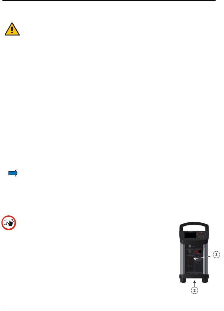
Ensure a free supply of air to the internal fan located at the bottom of the instrument (pos. 2). The area around the calibrator should be free of draught, dirt, flammable substances etc.
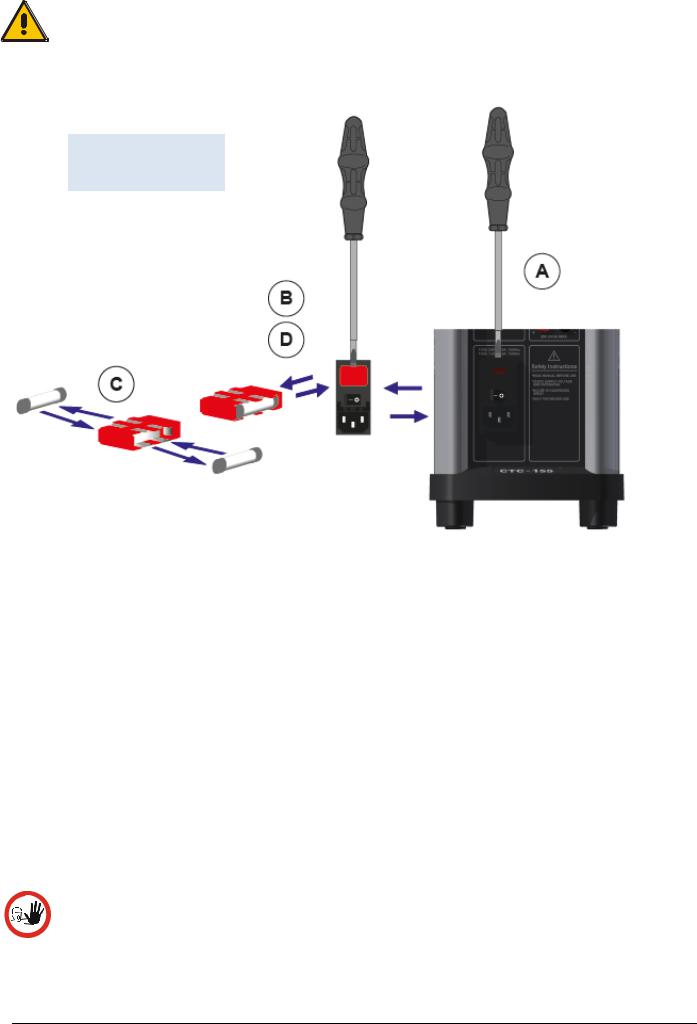
Check that the fuse size corresponds to the applied voltage on (pos. 3). The fuse is contained in the power control switch (on/off switch
(230V/115V)). To check; do as follows (see Fig. 1):
129375 00 |
2016-05-18 |
11 |
Warning
The two main fuses must have the specified current and voltage rating and be of the specified type. The use of makeshift fuses and the short-circuiting of fuse holders are prohibited and may cause a hazard.
Fig. 1
Changing fuses
A.Open the fuse box lid using a screwdriver.
B.Take out the fuse box.
C.Remove both fuses replacing them with two new fuses. These must be identical and should correspond to the line voltage. See section 11.0.
D.Slide the fuse box back into place.
Check that the earth connection for the instrument is present and attach the cable.
Select an insertion tube with the correct bore diameter. See section 3.2 for information on how to select insertion tubes.
The calibrator is now ready for use.
3.2Choosing an insertion tube
Caution…
To get the best results out of your calibrator, the insertion tube dimensions, tolerance and material are critical. We highly advise using the JOFRA insertion tubes, as they guarantee trouble free operation. Use of other insertion tubes may reduce performance of the calibrator and cause the insertion tube to get stuck.
129375 00 |
2016-05-18 |
12 |

Caution…
Before using new insertion tubes for the calibration in the CTC-350/660 instruments the insertion tubes must be heated up to maximum temperature 350°C(662°F) / 660°C (1220°F) for a period of minimum 30 minutes.
Insertion tubes are selected on the basis of the diameter of the sensor to be calibrated. Use the table for insertion tubes in section 3.2.1 to find the correct parts number.
Alternatively, you may order an undrilled insertion tube and drill the required hole yourself. The finished dimension should be as follows:
Sensor diameter ød+0.2 +0.05 / -0.00 mm.
Reference sensor hole ø4.2mm +0.05 / -0.00 mm
3.2.1Standard insertion tubes
Caution…
To get the best results out of your calibrator, the insertion tube dimensions, tolerance and material are critical. We highly advise using the JOFRA insertion tubes, as they guarantee trouble free operation. Use of other insertion tubes may reduce performance of the calibrator and cause the insertion tube to get stuck.
PARTS NO. FOR STANDARD INSERTION TUBES – SINGLE HOLES
|
Sensor |
CTC-155 |
CTC-350 |
CTC-660 |
Sensor |
CTC-155 |
CTC-350 |
CTC-660 |
|
size |
size |
||||||
|
|
|
|
|
|
|
||
|
3 mm |
129407 |
129429 |
129459 |
Undrilled |
129418 |
129445 |
129475 |
|
4 mm |
129408 |
129430 |
129460 |
Undrilled/ref. hole |
129419 |
129446 |
129476 |
|
5 mm |
129409 |
129431 |
129461 |
1/8” |
129420 |
129447 |
129477 |
|
6 mm |
129410 |
129432 |
129462 |
3/16” |
129421 |
129448 |
129478 |
|
7 mm |
129411 |
129433 |
129463 |
1/4” |
129422 |
129449 |
129479 |
|
8 mm |
129412 |
129434 |
129464 |
5/16” |
129423 |
129450 |
129480 |
|
9 mm |
129413 |
129435 |
129465 |
3/8” |
129424 |
129451 |
129481 |
|
10 mm |
129414 |
129436 |
129466 |
7/16” |
129425 |
129452 |
129482 |
|
11 mm |
129415 |
129437 |
129467 |
1/2” |
129426 |
129453 |
129483 |
|
12 mm |
129416 |
129438 |
129468 |
9/16” |
129427 |
129454 |
129484 |
|
13 mm |
129417 |
129439 |
129469 |
5/8” |
129428 |
129455 |
129485 |
|
14 mm |
- |
129440 |
129470 |
11/16”* |
- |
129456 |
129486 |
|
15 mm |
- |
129441 |
129471 |
13/16”* |
- |
129457 |
129487 |
|
16 mm* |
- |
129442 |
129472 |
3/4”* |
- |
129458 |
129488 |
|
18 mm* |
- |
129443 |
129473 |
|
|
|
|
|
20 mm* |
- |
129444 |
129474 |
|
|
|
|
|
|
|
|
|
|
|
|
|
The CTC-155 single-hole insertion tubes are delivered with a matching insulation plug.
*Note: Insertion tubes without reference holes.
129375 00 |
2016-05-18 |
13 |
PART NO. FOR STANDARD INSERTION TUBES – MULTI-HOLE
|
Description |
CTC-155 |
CTC-350 |
CTC-660 |
|
|
|
|
|
|
|
|
Metric Type 1 |
|
|
|
|
|
Sensor size |
|
|
|
|
|
3, 4, 5, 6, 9 mm and |
129489 |
129491 |
129493 |
|
|
4mm REF |
|
|
|
|
|
Inch Type 2 |
|
|
|
|
|
Sensor size |
129490 |
|
|
|
|
1/8”, 3/16”, 1/4”, 3/8” and |
129492 |
129494 |
|
|
|
4 mm REF |
|
|
|
|
The CTC-155 multi-hole insertion tubes are delivered with a matching insulation plug.
3.3Inserting the sensor
Before inserting the sensor and switching on the calibrator, please note the following important warning:
Warning
Never use heat transfer fluids such as silicone, oil, paste, etc. in the dry-block calibrators.
These fluids may penetrate the calibrator and cause electrical hazard, damage or create poisonous fumes.
Never try to modify the insulation plugs to make them fit the sensor. Use only insulation plugs supplied by AMETEK Denmark A/S.
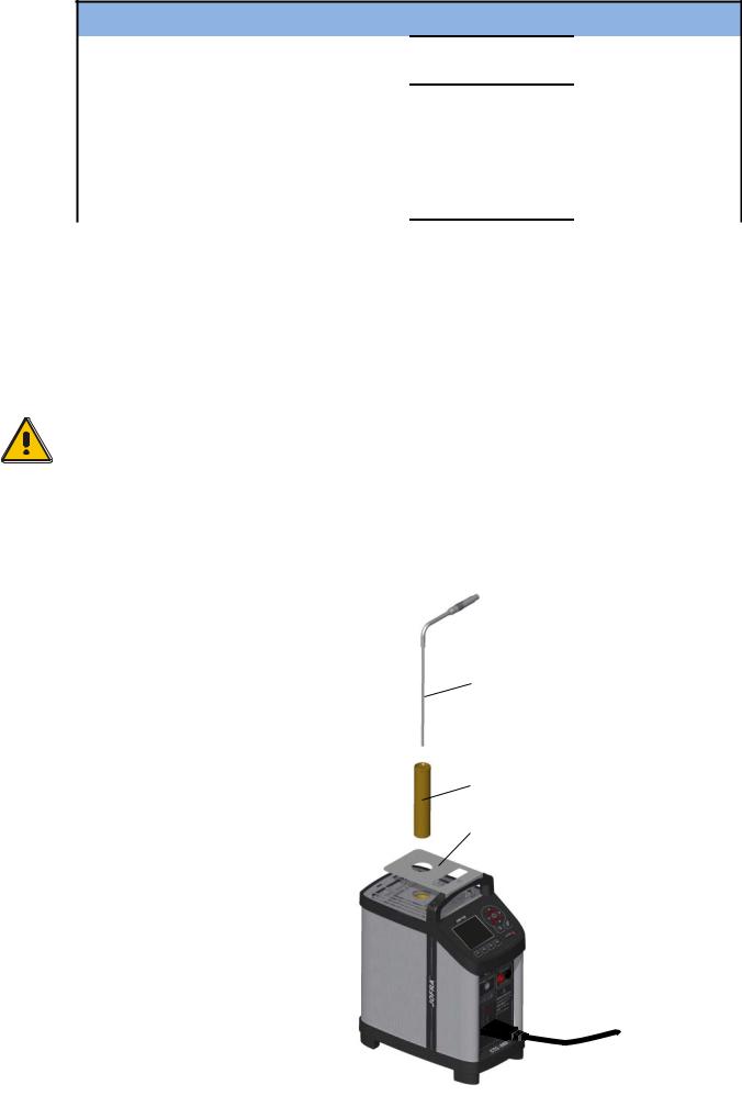
Insert the sensor as shown below in fig. 2.
Fig. 2 |
|
|
Inserting sensor and |
Sensor under test |
|
insertion tube |
||
|
||
|
|
Insertion tube
Thermal protection shield
|
|
|
|
129375 00 |
2016-05-18 |
14 |
|
Check that the insulation plug fits the diameter of the sensor. Otherwise replace it (CTC-155 only).
In order to spare the sensor and its connections it is recommended to use a thermal protection shield (129264) at high temperatures (CTC-350/660 only).
Caution…
The well and the insertion tube must be clean before use.
Do not pour any form of liquids in the well. It might damage the well.
Scratches and other damage to the insertion tubes should be avoided by storing the insertion tubes carefully when not in use.
The insertion tube must never be forced into the well. The well could be damaged as a result, and the insertion tube may get stuck.
Caution – Hot surface
Do not touch the grid plate, the well or the insertion tube as the calibrator is heating up – they may be very hot and cause burns.
Do not touch the tip of the sensor when it is removed from the insertion tube/well
– it may be very hot and cause burns.
Do not touch the handle of the calibrator during use – it may be very hot and cause burns.
Do not remove the insertion tube from the calibrator before the insertion tube has cooled down to less than 50°C/122°F.
Caution – Cold surface
Below 0°C/32°F (applies only to the CTC-155 models)
Do not touch the well or insertion tube when these are below 0°C/32°F - they might create frostbite.
If the calibrator has reached a temperature below 0°C/32°F, ice crystals may form on the insertion tube and the well. This, in turn, may cause the material surfaces to oxidize
To prevent this from happening the insertion tube and the well must be dried. This is done by heating up the calibrator to 100°C/212°F until all water left has evaporated.
Remove the insulation plug while heating up.
It is very important that humidity in the well and insertion tube is removed to prevent corrosion and frost expansion damages.
129375 00 |
2016-05-18 |
15 |

3.4Programming intelligent STS sensors
Use the configuration software CON050 supplied with CTC to program and to update calibration information in intelligent STS sensors.
For instructions read the software manual for CON050 installed on the USB key.
129375 00 |
2016-05-18 |
16 |

4.0Calibrator Interface
4.1Keypad - Functions
Function keys F1, F2, F3, F4
To operate the horizontal menu bar use the Functions keys.
System menu key
Press the key to enter the System menu.
Back key
Press the key to cancel a selection or return to previous menu.
Arrow Keys
Serve different functions depending on the mode of operation.
Navigation mode: Use the four keys to move the cursor in the desired direction.
Edit mode: The Up and Down Arrow keys scroll through the lists of options. If entering a number, the Left and Right Arrow keys move the cursor one character in the desired direction.
Action key / Enter key
Action function: Open and close edit fields or a menu button. The action key also accepts the selected option or entered value.
Enter function: Accept selected options or entered values. When a value is entered with the Enter Key the cursor selects the next configurable field in the list.
4.2Display - Functions
Reference sensor info |
|
Memory reading |
|
|
Warning/Error |
||
Shows the reference sensor |
|
Shows the current |
|
|
symbols. See 4.2.2 |
||
selected. The serial number |
|
memory selected |
|
|
|
|
|
|
|
|
|
|
|
||
of the external reference |
|
from the System |
|
|
Real Time Clock and |
||
sensor is read from the |
|
menu. |
|
|
date display. |
||
intelligent reference sensor |
|
|
|
|
|
|
|
|
|
|
|
|
|
||
and displayed in this field. |
|
|
|
|
|
|
|
|
|
|
|
|
|
|
|
|
|
|
|
|
|
|
|
“Time to stable” |
|
|
|
|
|
|
|
|
|
|
|
|
|
|
|
Selection |
|
|
|
|
|
|
|
Shows the selected |
|
|
|
|
|
|
|
specified stability criteria |
|
|
|
|
|
|
|
and states a time when the |
|
|
|
|
|
|
|
stable situation can be |
|
|
|
|
|
|
|
achieved. |
|
|
|
|
|
|
|
|
|
|
|
|
|
||
|
|
|
|
|
|
|
|
Process Indicator |
|
Horizontal menu bar |
|
|
|
||
Indicates the status of the |
|
Provides you with the relevant menu |
|||||
current process. |
|
options that can be selected at the |
|||||
|
|
present point. Each option can be |
|||||
|
|
||||||
selected and activated by pressing the function keys (F1, F2, F3 and F4).
True temperature reading
Shows the numeric value of the temperature being measured. Can be either the internal reference sensor or an external reference sensor.
Units
Shows the unit of the current measurement.
Internal Reference temperature reading
Shows the temperature of the well.
Set temperature reading
Shows the numeric value of the current set temperature selected.
129375 00 |
2016-05-18 |
17 |
 Loading...