


 Loading...
Reference Manual
Advanced Signal Calibrator
ASC-400

Reference Manual
Advanced Signal Calibrator
JOFRA ASC-400
Copyright 2014 AMETEK Denmark A/S
About this manual….
The structure of the manual
This reference manual is aimed at users who are familiar with AMETEK signal calibrators, as well as those who are not. The manual is divided into 12 chapters, which describe how to set up, operate, service and maintain the signal calibrator. The technical specifications are described and accessories may be ordered from the list of accessories.
Safety symbols
This manual contains a number of safety symbols designed to draw your attention to instructions, which must be followed when using the instrument, as well as any risks involved.
Warning
Conditions and actions that may compromise the safe use of the instrument and result in considerable personal or material damage.
Caution…
Conditions and actions that may compromise the safe use of the instrument and result in slight personal or material damage.
Note…
Special situations, which demand the user’s attention.
128797 03 |
2015-04-22 |
2 |

List of contents
1.0 |
Introduction ..................................................................................................................................... |
5 |
||
|
1.1 |
Warranty ..................................................................................................................................................... |
6 |
|
|
1.2 |
Receiving the Advanced Signal Calibrator ................................................................................................. |
6 |
|
|
1.3 |
Dimensioning drawing ................................................................................................................................ |
7 |
|
2.0 |
Safety instructions .......................................................................................................................... |
8 |
||
3.0 |
Calibrator Interface ....................................................................................................................... |
10 |
||
|
3.1 |
Input/Output Connections ......................................................................................................................... |
10 |
|
|
3.2 |
Keypad - Functions................................................................................................................................... |
11 |
|
|
3.3 |
Main display - Functions ........................................................................................................................... |
11 |
|
|
3.4 |
Upper display (Read-back display) - Functions........................................................................................ |
12 |
|
|
3.5 |
Lower display (Primary display) – Functions ............................................................................................ |
12 |
|
4.0 |
Operating the calibrator................................................................................................................ |
13 |
||
|
4.1 |
Basic operation (Setup) ............................................................................................................................ |
13 |
|
|
4.2 |
The principle of navigating through a Setup ............................................................................................. |
14 |
|
|
4.3 |
System Settings........................................................................................................................................ |
15 |
|
|
|
4.3.1 Power Saver (Auto off)................................................................................................................. |
16 |
|
5.0 Using measure modes (lower display)........................................................................................ |
18 |
|||
|
5.1 |
Measuring volts......................................................................................................................................... |
18 |
|
|
5.2 |
Measuring frequency ................................................................................................................................ |
19 |
|
|
5.3 |
Measuring mA........................................................................................................................................... |
20 |
|
|
5.4 |
Measuring Temperature ........................................................................................................................... |
21 |
|
|
|
5.4.1 |
Using Thermocouples (TC).......................................................................................................... |
21 |
|
|
5.4.2 |
Using Resistance-Temperature-Detectors (RTDs)...................................................................... |
22 |
|
5.5 |
Measuring Pressure.................................................................................................................................. |
25 |
|
|
|
5.5.1 Zeroing with Absolute Pressure Modules (APM S, H and Mk.II) ................................................. |
26 |
|
|
|
5.5.2 Using the BARO Module (optional).............................................................................................. |
26 |
|
6.0 Using Source modes (Lower Display)......................................................................................... |
28 |
|||
|
6.1 |
Sourcing mA (internal loop power supply)................................................................................................ |
28 |
|
|
6.2 |
mA Sink (external loop power supply) ...................................................................................................... |
29 |
|
|
6.3 |
Sourcing Voltage....................................................................................................................................... |
30 |
|
|
6.4 |
Sourcing Frequency.................................................................................................................................. |
31 |
|
|
6.5 |
Sourcing a Pulse Train ............................................................................................................................. |
31 |
|
|
6.6 |
Sourcing mV ............................................................................................................................................. |
32 |
|
|
6.7 |
Sourcing Thermocouples.......................................................................................................................... |
33 |
|
|
6.8 |
Sourcing Ohms/RTDs............................................................................................................................... |
34 |
|
|
6.9 |
Custom RTD ............................................................................................................................................. |
35 |
|
|
6.10 Using Auto Output functions ..................................................................................................................... |
36 |
||
|
|
6.10.1 Using the Step function................................................................................................................ |
36 |
|
|
|
6.10.2 Using the Ramp function.............................................................................................................. |
37 |
|
7.0 Using Isolated Measure Modes (Upper Display) ........................................................................ |
39 |
|||
|
7.1 |
Measuring mA (external loop supply) ....................................................................................................... |
39 |
|
|
7.2 |
Measuring current with internal loop power.............................................................................................. |
40 |
|
|
7.3 |
Measuring Voltage.................................................................................................................................... |
41 |
|
|
7.4 |
Measuring Pressure.................................................................................................................................. |
41 |
|
8.0 |
Using the Upper and Lower Display for Calibration and Testing ............................................ |
43 |
||
|
8.1 |
Performing a Temperature Switch Test.................................................................................................... |
43 |
|
|
8.2 |
Performing a Pressure Switch Test .......................................................................................................... |
45 |
|
|
8.3 |
Testing an Input or Indicating Device ....................................................................................................... |
47 |
|
|
8.4 |
Calibrating an I/P Device .......................................................................................................................... |
47 |
|
|
8.5 |
Calibrating a Transmitter (Signal Converter) ............................................................................................ |
49 |
|
|
8.6 |
Calibrating a Pressure Transmitter (loop powered 4-20 mA) ................................................................... |
50 |
|
|
|
|
|
|
128797 |
03 |
2015-04-22 |
3 |
|
|
8.7 |
Using Scaled Current or Voltage when testing or calibrating a T/I Transmitter |
.....................................52 |
|
8.8 |
Using Percent Error when testing or calibrating a T/I Transmitter............................................................ |
53 |
9.0 |
Maintenance................................................................................................................................... |
54 |
|
|
9.1 |
Returning the calibrator to service............................................................................................................ |
54 |
|
9.2 |
Replacing batteries ................................................................................................................................... |
56 |
|
9.3 |
Storing....................................................................................................................................................... |
57 |
|
9.4 |
Cleaning.................................................................................................................................................... |
57 |
10.0 |
Errors.............................................................................................................................................. |
58 |
|
11.0 |
Technical specifications............................................................................................................... |
59 |
|
12.0 |
List of accessories........................................................................................................................ |
67 |
|
128797 03 |
2015-04-22 |
4 |

1.0Introduction
Congratulations on your new AMETEK JOFRA Advanced Signal Calibrator!
With the AMETEK JOFRA Advanced Signal Calibrator, you have chosen an extremely effective instrument, which we are sure will perform according to your expectations.
This ASC-400 signal calibrator is a handheld, battery or DC adaptor powered instrument that measures and sources electrical and physical parameters.
During the past several years, we have acquired extensive knowledge of industrial signal calibration. This expertise is reflected in our products, which are all designed for daily use in an industrial environment. Please note that we would be very interested in hearing from you if you have any ideas or suggestions for changes to our products.
This reference manual applies to the following instrument:
JOFRA ASC-400
The calibrator has the following features and functions:
A dual colour display.
The upper display is used for the measurement of volts, current, pressure, %error, scaling and switch test
The lower display can be used to measure and source volts, millivolts, current, pressure, resistance, resistance temperature detectors (RTDs), thermocouples, frequency, and resistance, and to source pulse trains.
A thermocouple (TC) input/output terminal with automatic and manual reference-junction (cold junction) temperature compensation.
An interactive and intuitive user interface
USB interface for remote control
Isolated read back for transmitter calibration.
A BARO option turning any gauge measuring APM into an absolute measuring device.
Extended and comprehensive pressure measurement capabilities with JOFRA advanced pressure modules (APM)
ISO-9001 certified
AMETEK Denmark A/S was ISO-9001 certified in September 1994 by Bureau Veritas
Certification Denmark.
CE-label
Your new signal calibrator bears the CE label and conforms to the EMC
Directive.
128797 03 |
2015-04-22 |
5 |
Technical assistance
Please contact the dealer from whom you acquired the instrument if you require technical assistance.
1.1Warranty
This instrument is warranted against defects in workmanship, material and design for two (2) years from date of delivery to the extent that AMETEK will, at its sole option, repair or replace the instrument or any part thereof which is defective, provided, however, that this warranty shall not apply to instruments subjected to tampering or, abuse, or exposed to highly corrosive conditions.
THIS WARRANTY IS IN LIEU OF ALL OTHER WARRANTIES WHETHER EXPRESS OR IMPLIED AND AMETEK HEREBY DISCLAIMS ALL OTHER WARRANTIES,
INCLUDING, WITHOUT LIMITATION, ANY WARRANTY OF FITNESS FOR A PARTICULAR PURPOSE OR MERCHANTABILITY. AMETEK SHALL NOT BE LIABLE
FOR ANY INCIDENTAL OR CONSEQUENTIAL DAMAGES, INCLUDING, BUT NOT LIMITED TO, ANY ANTICIPATED OR LOST PROFITS.
This warranty is voidable if the purchaser fails to follow any and all instructions, warnings or cautions in the instrument’s User Manual.
If a manufacturing defect is found, AMETEK will replace or repair the instrument or replace any defective part thereof without charge; however, AMETEK’s obligation hereunder does not include the cost of transportation, which must be borne by the customer. AMETEK assumes no responsibility for damage in transit, and any claims for such damage should be presented to the carrier by the purchaser.
1.2Receiving the Advanced Signal Calibrator
When you receive the instrument…
1)Unpack and check the signal calibrator and the accessories carefully.
2)Check the parts according to the list shown below.
If any of the parts are missing or damaged, please contact the dealer who sold you the signal calibrator.
You should receive:
1 ASC-400 Calibrator
1 electronic Reference manual on USB memory stick
2 sets of test leads and test clips (black and red)
1 carrying soft bag
1 USB cable
6 x AA batteries
1 Calibration certificate (International traceable)
When reordering, please specify the part numbers according to the list of accessories, section 12.0
128797 03 |
2015-04-22 |
6 |
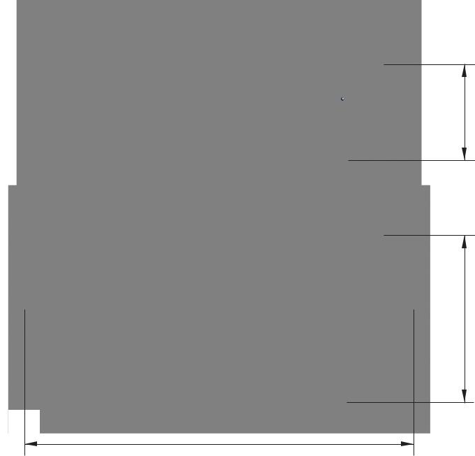
1.3Dimensioning drawing
55 mm
96 mm
220 mm
128797 03 |
2015-04-22 |
7 |
2.0Safety instructions
Read this manual carefully before using the instrument!
Please follow the instructions and procedures described in this manual. They are aimed at allowing you to make the best of your signal calibrator and avoid any personal injuries and/or damage to the instrument.
Disposal – WEEE Directive
The signal calibrator contains Electrical and Electronic circuits and must be properly recycled or disposed of (in accordance with the WEEE Directive 2002/96/EC).
Warning
The signal calibrator is designed to calibrate and measure low voltage process signals.
To ensure the safety of the operator and the instrument, DO NOT connect the signal calibrator to input voltages above 30 Volts.
To avoid possible electric shock or personal injury:
Do not apply more than the rated voltage. See specifications for supported ranges.
Follow all equipment safety procedures.
Never touch the probe to a voltage source when the test leads are plugged into the current terminals.
Do not use the calibrator if it is damaged. Before you use the calibrator, inspect the case. Look for cracks or missing plastic. Pay particular attention to the insulation surrounding the connectors.
Select the proper function and range for your measurement.
Make sure the battery cover is closed and latched before you operate the calibrator.
Remove test leads from the calibrator before you open the battery door.
Inspect the test leads for damaged insulation or exposed metal. Check test leads continuity. Replace damaged test leads before you use the calibrator.
When using the probes, keep your fingers away from the probe contacts. Keep your fingers behind the finger guards on the probes.
Connect the common test lead before you connect the live test lead.
When you disconnect test leads, disconnect the live test lead first.
Do not use the calibrator if it operates abnormally. Protection may be impaired. When in doubt, have the calibrator serviced.
Do not operate the calibrator around explosive gas, vapour, or dust.
When using a pressure module, make sure the process pressure line is shut off and depressurized before you connect it or disconnect it from the pressure module.
Disconnect test leads before changing to another measure or source function.
When servicing the calibrator, use only specified replacement parts.
To avoid false readings, which could lead to possible electric shock or personal injury, replace the battery as soon as the battery indicator appears.
To avoid a violent release of pressure in a pressurized system, shut off the valve and slowly bleed off the pressure before you attach the pressure module to the pressure line.
To avoid personal injury or damage to the calibrator, use only the specified replacement parts and do not allow water into the case.
128797 03 |
2015-04-22 |
8 |
Caution…
To avoid possible damage to the signal calibrator or to the equipment under test:
Disconnect the power and discharge all high-voltage capacitors before testing resistance or continuity.
Use the proper jacks, function, and range for your measurement or sourcing application.
If the message changes to "OL" the range limit is exceeded and the pressure source must immediately be removed from the APM to prevent damage to the pressure transducer inside.
To avoid damaging the pressure module from overpressure, never apply pressure above the rated maximum printed on the module.
To avoid damaging the plastic lens and case, do not use solvents or abrasive cleansers.
When using the switch test function, make sure that no other equipment, such as heavy loads or sources, is connected in the test loop.
Note…
The product liability only applies if the instrument is subject to a manufacturing defect. This liability becomes void if the user fails to follow the maintenance instructions described in this manual or uses unauthorized spare parts.
128797 03 |
2015-04-22 |
9 |
3.0Calibrator Interface
3.1Input/Output Connections
Measure / Source mA
Input terminals for sourcing and measuring current.
Measure / Source V, Ω/RTD, Hz
Input terminals for sourcing and measuring voltage, frequency, pulse train, resistance and RTDs.
TC mV input / output
Terminal for measuring or simulating thermocouples and mV. Accepts miniature polarized thermocouple plugs with flat in-line blades spaced 7.9 mm (0.312 in) center to center.
Pressure module connector (APM)
Connects calibrator to a pressure module for pressure measurements.
Measure / V mA
Input terminals for measuring , switch test, current, voltage and supplying
Measure Ω/RTD, 4w, 3/4w
Input terminals for performing RTD measurements with 3-wire or 4- wire setups.
USB connection |
|
Charger Connector |
Connects calibrator |
|
Connects to optional |
to a PC for remote |
|
power supply / |
control. |
|
battery charger. |
|
|
|
128797 03 |
2015-04-22 |
10 |
3.2Keypad - Functions
Power key/ Backlight key
Turn the calibrator on and off. Press the button for five seconds to turn it off. Adjust the backlight intensity.
Arrow Keys
Have different functions depending on the mode of operation. In navigation mode, they move the cursor in the desired direction.
In edit mode, they roll in the list of options or if entering a number, the arrow left and arrow right move the cursor one character in the desired direction.
Zero key
Zero Pressure Module reading.
Numeric Keypad
Allows user to enter Numeric values in both upper and lower display.
Function keys F1, F2, F3, F4
To operate the menu bar at the bottom of the calibrator display, use the F-keys.
Back key
Cancel a selection / edit or return to previous menu.
Action key / Enter key
Action function: Open and close edit fields or a menu button. The action key also accepts the selected option or entered value.
Enter function: Accept selected options or entered values. When a value is entered with the Enter Key the cursor selects the next value field in the list.
Configuration key
Opens and closes configuration mode.
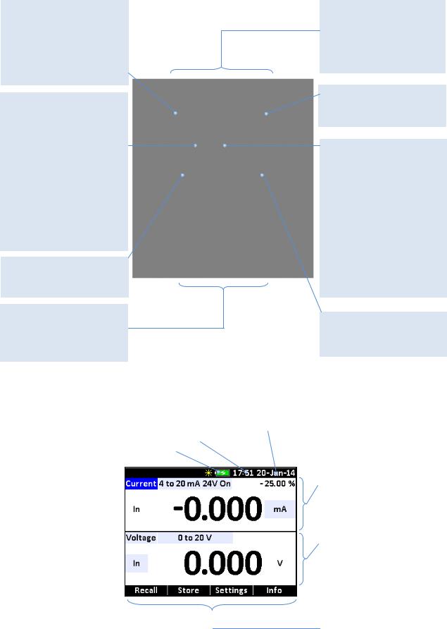
3.3Main display - Functions
|
Battery icon. |
|
Real Time |
|
Date display |
|
Upper display |
|
|
|
|
Remaining power and |
|
Clock display |
|
|
|
The upper display is used |
|
|
|
|
|
|
|
|
||||||
|
attached power adapter |
|
|
|
|
|
|
for measuring DC voltage, |
|
|
|
|
|
|
|
||||||
|
|
|
|
|
|
|
|
DC current with and |
|
|
|
|
|
|
|
|
|
|
|
|
|
|
|
|
|
|
|
|
|
without loop power, |
|
|
|
|
|
|
|
|
|
|
pressure, percent, error, |
|
|
|
|
|
|
|
|
|
|
scaled value, switch test. |
|
|
|
|
|
|
|
|
|
|
|
|
|
|
|
|
|
|
|
|
|
|
|
|
|
|
|
|
|
|
|
|
Lower display |
|
|
|
|
|
|
|
|
|
|
The lower display can be |
|
|
|
|
|
|
|
|
|
|
used for both measuring |
|
|
|
|
|
|
|
|
|
|
and sourcing. |
|
|
|
|
|
|
|
|
|
|
|
||
|
|
|
|
|
|
|
|
Horizontal menu bar |
|
|
|
|
|
|
|
|
|
|
The menu bar is used to |
|
|
|
|
|
|
|
|
|
|
setup both the upper and |
|
|
|
|
|
|
|
|
|
|
the lower display to perform |
|
|
|
|
|
|
|
|
|
|
the desired function. The |
|
|
|
|
|
|
|
|
|
|
function keys (F1, F2, F3 |
|
|
|
|
|
|
|
|
|
|
and F4) are used to |
|
|
|
|
|
|
|
|
|
|
navigate through all the |
|
|
|
|
|
|
|
|
|
|
levels and choices of the |
|
|
|
|
|
|
|
|
|
|
menu bar. |
|
|
|
|
|
|
|
|
|
|
|
|
|
128797 03 |
|
|
2015-04-22 |
|
|
|
11 |
|||
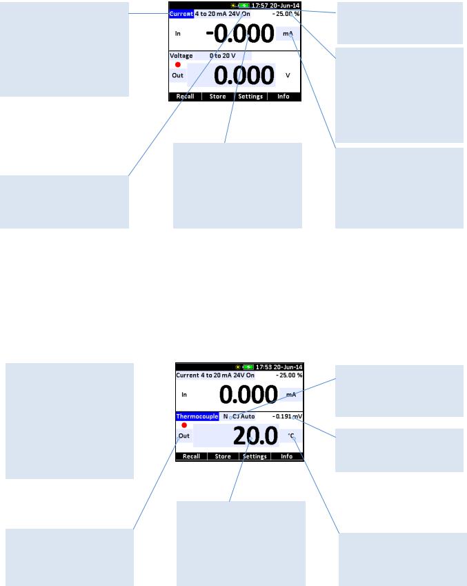
3.4Upper display (Read-back display) - Functions
Primary Parameters
Determine what parameter is going to be measured.
The available options for the upper display are: CURRENT, VOLTAGE, SWITCH TEST, PRESSURE and LEAK TEST.
Additional parameters
Selection and selection of parameters relevant to the choice of primary parameter
Numeric display
Displays the numeric values of the signal being measured.
An “OL” reading indicates an out of range or overload condition.
Backlight Intensity
Indicates Low, Medium or High intensity on backlight
Secondary upper display
Shows where in the preset span the measured value falls. Fixed for mA at 4 (0%) and 20 (100%). Also shows mA value for percent error, mA or Volts value for scaling and leak rate for pressure.
Units
Shows what unit the measurement value is in. Available options are : mA, SCALING, %ERROR, VOLT and PRESSURE UNITS.
3.5Lower display (Primary display) – Functions
Primary Parameters
Determine what parameter is going to be measured or sourced.
The available options for the  upper display are: CURRENT,
VOLTAGE, THERMOCOUPLE, RTD, OHMS,
FREQUENCY, PULSE, PRESSURE and BARO (opt.)
Input / Output
Switches / indicates lower display input mode (read), and output mode (source).
Numeric display
Displays the numeric values of the signal being measured, or sourced.
An “OL” reading indicates an out of range or overload condition.
Additional parameters
Selection and selection of parameters relevant to the choice of primary parameter.
Native Value
0 to 100 % in mA out mode and leak rate for pressure.
Units
Shows what unit the measurement or source value is in.
128797 03 |
2015-04-22 |
12 |
4.0Operating the calibrator
Warning
Please inspect the Safety Instructions in section 2.0 before using the instrument.
Caution…
Please inspect the Safety Instructions in section 2.0 before using the instrument.
Connect USB cable and APM before switching on the instrument, or before applying DC power.
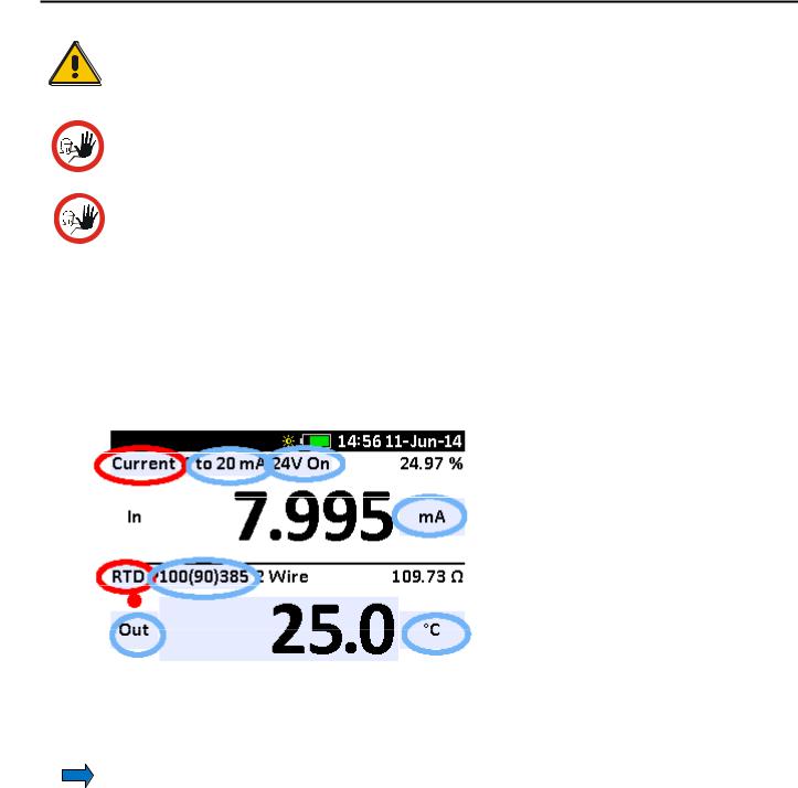
4.1Basic operation (Setup)
1.Select mode for upper and lower display (RED markers).
2.Select the related options and functions for the selected modes (BLUE markers)
Note…
the light blue fields; they indicate a parameter / function that can be selected or altered in edit mode. This works like a build in user manual, indicating the changeable parameters for the selected mode at all times.
128797 03 |
2015-04-22 |
13 |

4.2The principle of navigating through a Setup
ACTION |
SCREEN DISPLAYED |
|
|
1. |
Press |
to access edit mode. |
2. Use the (ARROW) keys to move between the parameter fields.
3.Press  to access the various Parameter lists to choose from.
4.Start by selecting upper or lower display.
5. Use the (ARROW) keys to move between the parameter fields and make more changes…
6. |
Press |
to accept the selections and leave the |
|
edit mode. |
|
7.Use the numeric keys to enter an output value (if output if chosen).
8.Press to accept the value.
9. Or use the |
(ARROW) keys to enter “fine adjust” |
|||
mode. |
|
|
|
|
Move the value-frame to the right or left using the |
|
|||
or |
keys. Modify the digits using the |
or |
keys. |
|
128797 03 |
2015-04-22 |
14 |
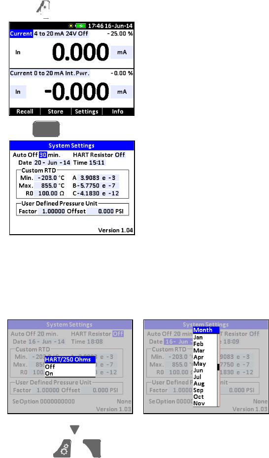
4.3System Settings
The System Settings setup can be accessed at any stage of operation:
1. Press 


 to display the Horizontal menu bar.
2. Press F3 |
(System) to access the System Settings. |
3.Use the  (ARROW) keys to move between the setting fields.
4.Press  to open a setting field for editing.
5.Use the numeric keys to enter the desired value and press  to accept the value.
When entering the HART Resistor ON/OFF field and Date field horizontal lists appear.
6. Use the  and
and
7. Press either |
keys to scroll in the lists and select from the lists by pressing . or
. or
 to exit the System Settings.
128797 03 |
2015-04-22 |
15 |
8.The calibrator resumes normal operation after a few seconds. It will return to the setup last used.
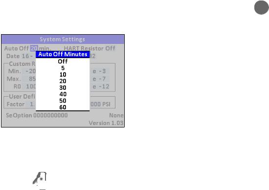
4.3.1Power Saver (Auto off)
The ASC-400 calibrator automatically turns off 5 to 60 minutes after the last keystroke. To reduce or increase this time or to disable this feature, do as follows:
1.In the System Settings setup enter the “Auto Off” setting field and press  to access the Auto Off Minutes list.
2.The list displays the turn-off time in minutes.
Off disables the power saver and the calibrator will be permanently off.
3.Select the turn-off time by pressing  .
.
4.Press 


 to exit the System Settings.
128797 03 |
2015-04-22 |
16 |
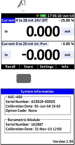
4.4System Information
The System Information can be accessed at any stage of operation:
1. Press  to display the Horizontal menu bar.
2. Press |
F4 |
(Info) to access the System Information. |
|
128797 03 |
2015-04-22 |
17 |

5.0Using measure modes (lower display)
5.1Measuring volts
The electrical parameter volts can be measured using the lower display.
To make the desired measurements, follow the principle of navigating through the functions described in the guidelines in section 4.2 and proceed as follows:
1.Select “Voltage” from the Lower Mode list.
2.Select the desired Range from the Range list.
3.Select the desired Test Mode (in) from the Test Mode list.
4.Accept the selections and leave the edit mode.
5. Connect the leads, as shown in Figure 1.
Figure 1
Measuring Volts
128797 03 |
2015-04-22 |
18 |
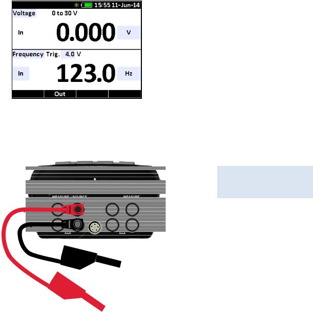
5.2Measuring frequency
The electrical parameter frequency can be measured using the lower display.
To make the desired measurements, follow the principle of navigating through the functions described in the guidelines in section 4.2 and proceed as follows:
1.Enter edit mode.
2.Select “Frequency” from the Lower Mode list.
3.Select the desired Test Mode (In) from the Test Mode list.
4.Enter the desired trigger level (Trig. V) value using either the ARROW keys or the numeric keys.
5.Select the desired unit from the Units list.
6.Accept the selections and leave edit mode.
7. Connect the leads, as shown in Figure 2.
Figure 2
Measuring Frequency
128797 03 |
2015-04-22 |
19 |
5.3Measuring mA
The electrical parameter mA can be measured using the lower display.
Follow the principle of navigating through the functions as described in the guidelines in section 4.2 to make the desired mA measurements:
1.Enter edit mode.
2.Select “Current” from the Lower Mode list.
3.Select the desired Test Mode (In) from the Test Mode list.
4.Select the desired Range from the Range list.
5.Select the desired power source from the Power Source list.
6.Select mA or % from the Units list.
7.Accept the selections and leave edit mode.
8.Connect the leads, as shown in Figure 3.
Figure 3
Measuring mA
|
|
|
|
|
|
|
|
128797 03 |
2015-04-22 |
20 |
|
Loading...