


FBD-NT Press Brake
Machine Description
General view of machine ............................................................. |
2 |
Functions..................................................................................... |
4 |
Specifications............................................................................... |
8 |
Machine.................................................................................... |
8 |
Numerical controls ................................................................... |
9 |
List of standard NC functions ................................................... |
9 |
Accessories for voltage change .............................................. |
10 |
Dimensions of machine........................................................... |
11 |
Backgauge.................................................................................. |
12 |
One-touch stopper fingers....................................................... |
12 |
Worksheet overhang ............................................................... |
13 |
1
GENERAL VIEW OF MACHINE
NOTE
● This drawing shows the general view of the FBDIII-8025NT.
2

3
FUNCTIONS
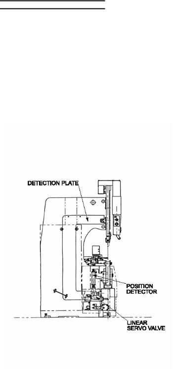
This machine is a press brake whose lower beam is hydraulically raised by the linear servo valves at the right and left sides. The UP and DOWN foot pedals are pressed to move up and down the lower beam. The punches are mounted in the punch holders attached to the upper beam, and the dies and die holders are mounted on the lower beam. The worksheet is laid over the dies, supported by hand, and bent by raising the lower beam onto the punches. The bend angle of the worksheet depends on the clearance between the dies and punches. The lower beam is moved up and down by the main cylinders installed on the right and left sides. The auxiliary cylinders are installed at the center of the lower beam to prevent a long worksheet from being bent with a greater angle toward the center (or to keep the clearance between the upper and lower beams uniform in the longitudinal direction). The bend angle is finely adjusted by the right and left linear servo valves, which can also be controlled independently to tilt the lower beam. This tilting function allows the difference in the bend angle between the right and left sides of the worksheet to be compensated for and the worksheet to be offset bent (or bent off the center of the machine). The worksheet can also be pushed against the stoppers of the backgauge to determine its bend position. The machine can be operated from the NC control box.
4
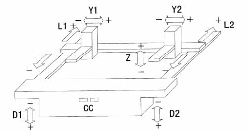
Coordinate system of axes
Basically, the machine is controlled by the D1, D2, L1, L2, Y1, Y2 and Z axes and CC value.
D1 axis: Axis along which the left main cylinder of the lower beam moves up and down D2 axis: Axis along which the right main cylinder of the lower beam moves up and down L1 axis: Axis along which the backgauge moves back and forth on the left ball screw L2 axis: Axis along which the backgauge moves back and forth on the right ball screw Y1 axis: Axis along which the left backgauge moves left and right
Y2 axis: Axis along which the right backgauge moves left and right Z axis: Axis along which the backgauge moves up and down CC value: Pressure of the auxiliary cylinders in the lower beam
5
 Loading...