


 Loading...
PRESS BRAKE (ZII)
RG35S–100
OPERATOR'S MANUAL
RG25-125-E02-200510

PREFACE Read this manual carefully to obtain a thorough knowledge of machine operation and maintenance. Be sure to follow the instructions to ensure proper procedures and prevent injuries and accidents. Do not operate the machine by guesswork. Keep the manual at hand and refer to it whenever you are not sure of how to perform any of the procedures.
Operator's Manual:
Press Brake (ZII) RG35S-100 © 2005 by AMADA CO., LTD.
No part of this publication may be photocopied or otherwise reproduced without the prior written permission of AMADA CO., LTD.
ii |
Printed in Japan |
|
CONTENTS
Part I |
Safety.................................................................................... |
I-1 |
|
|
1. |
Safety rules............................................................................ |
I-2 |
|
2. DANGER and WARNING plates........................................... |
I-10 |
|
Part II |
Description.......................................................................... |
II-1 |
|
|
1. |
Functions ............................................................................... |
II-2 |
|
2. |
General view .......................................................................... |
II-3 |
|
3. |
Specifications......................................................................... |
II-5 |
|
4. |
Dimensions ............................................................................ |
II-6 |
|
5. |
Standard accessories ............................................................ |
II-9 |
|
6. |
Options.................................................................................. |
II-10 |
Part III |
Installation.......................................................................... |
III-1 |
|
|
1. Summary............................................................................... |
III-2 |
|
|
|
1-1. Environmental conditions............................................... |
III-2 |
|
|
1-2. Input power source......................................................... |
III-2 |
|
|
1-3. Things to be supplied by customer ................................ |
III-3 |
|
2. |
Installation procedures.......................................................... |
III-4 |
|
|
2-1. Location.......................................................................... |
III-4 |
|
|
2-2. Lifting.............................................................................. |
III-5 |
|
|
2-3. Foundation ..................................................................... |
III-6 |
|
|
2-4. Placing ........................................................................... |
III-6 |
|
|
2-5. Leveling.......................................................................... |
III-6 |
|
|
2-6. Supplying hydraulic oil ................................................... |
III-8 |
|
|
2-7. Supplying electric power ................................................ |
III-8 |
Part IV |
Controls.............................................................................. |
IV-1 |
|
|
1. |
Controls on electrical enclosure............................................ |
IV-2 |
|
2. |
Controls on upper beam ....................................................... |
IV-3 |
|
3. |
Hydraulic equipment controls ............................................... |
IV-4 |
|
4. |
Other controls ....................................................................... |
IV-6 |
|
|
|
(Continued on next page.) |
iii
Part V |
Operation ............................................................................ |
V-1 |
|
|
1. |
Inspection before start of day’s work ..................................... |
V-3 |
|
2. |
Preparing for operation.......................................................... |
V-3 |
|
3. |
Turning on power................................................................... |
V-5 |
|
4. |
Removing tools ...................................................................... |
V-6 |
|
|
4-1. Preparing for removing tools........................................... |
V-6 |
|
|
4-2. Removing punches ......................................................... |
V-8 |
|
|
4-3. Removing dies ................................................................ |
V-9 |
|
5. |
Installing tools ....................................................................... |
V-11 |
|
|
5-1. Preparing for installing tools .......................................... |
V-11 |
|
|
5-2. Installing dies ................................................................. |
V-12 |
|
|
5-3. Installing punches .......................................................... |
V-14 |
|
6. |
Preparing for special bending............................................... |
V-16 |
|
|
6-1. Installing and removing punch holders .......................... |
V-16 |
|
|
6-1-1. Removing punch holders ........................................ |
V-16 |
|
|
6-1-2. Installing punch holders .......................................... |
V-17 |
|
|
6-2. Installing punches rearside front.................................... |
V-18 |
|
|
6-3. Installing wide dies......................................................... |
V-19 |
|
7. |
Other uses ............................................................................ |
V-20 |
|
|
7-1. Adjusting punch holders................................................. |
V-20 |
|
|
7-2. Using one-touch punch holders (option)........................ |
V-23 |
|
|
7-2-1. Installing and removing punches from front ............ |
V-25 |
|
|
7-2-2. Installing and removing punches by sliding them |
|
|
|
along groove of rear clamping plates ..................... |
V-28 |
|
|
7-2-3. Installing and removing rear clamping plates.......... |
V-29 |
|
8. |
Aligning tools ........................................................................ |
V-32 |
|
|
8-1. RG35S ........................................................................... |
V-32 |
|
|
8-2. RG50, RG80, and RG100.............................................. |
V-34 |
|
9. |
Setting tool origin .................................................................. |
V-37 |
|
10. Bending operation............................................................... |
V-38 |
|
|
|
10-1. Setting rising speed change position ........................... |
V-38 |
|
|
10-2. Setting multiple opening limit ....................................... |
V-39 |
|
|
10-3. Bending worksheet ...................................................... |
V-40 |
|
|
10-3-1. Temporarily setting multiple closing limit............... |
V-40 |
|
|
10-3-2. Setting worksheet.................................................. |
V-41 |
|
|
10-3-3. Setting bend angle ................................................ |
V-42 |
|
11. Turning off power ................................................................ |
V-44 |
|
|
12. Troubleshooting .................................................................. |
V-46 |
|
|
13. Clearing emergency stop condition .................................... |
V-48 |
|
iv
Part VI |
Maintenance....................................................................... |
VI-1 |
||
|
1. |
Inspection before start of day’s work .................................... |
VI-2 |
|
|
2. |
Maintaining hydraulic system................................................ |
VI-4 |
|
|
|
2-1. |
Checking hydraulic oil level............................................ |
VI-4 |
|
|
2-2. |
Changing hydraulic oil.................................................... |
VI-5 |
|
|
2-3. |
Maintaining tools ............................................................ |
VI-6 |
|
3. |
Lubrication ............................................................................ |
VI-7 |
|
|
4. |
Hydraulic circuit diagrams..................................................... |
VI-8 |
|
|
|
4-1. RG35S ........................................................................... |
VI-8 |
|
|
|
4-2. RG50, RG80, and RG100............................................. |
VI-10 |
|
|
5. |
Electric circuit diagrams....................................................... |
VI-13 |
|
v

vi

Part I
Safety
|
|
..................................................................................1. Safety rules |
I-2 |
2. DANGER and WARNING plates................................................. |
I-10 |
I-1

1. SAFETY RULES
Observe these safety rules to prevent injuries and accidents:
a)Never modify the machine. If the control circuit or other part of the machine is modified, the ram may malfunction.
b)Whenever the machine is not in use, remove the key from the POWER ON/OFF keyswitch, and hand it to the chief operator for custody.
c)Assign trained operators to the operation and maintenance of the machine.
d)Inspect the machine before the start of the day's work.
e)Install the machine with a rear clearance of at least 1000 mm {40 in.} where it is not exposed to direct sunlight. If the electrical equipment of the machine is overheated as a result, the machine may malfunction.
f ) Before starting the operation of the machine, check that there are no persons and obstacles around the machine. Pay particular attention to the rear of the machine. Never place hand tools and parts on the installed dies and the lower beam.
g) Never put your hand or hands between the punches and dies.
I-2

h)When changing the tools, strictly observe the following rules:
•Before installing and removing the dies, turn the POWER ON/OFF
keyswitch to OFF, remove the key from the keyswitch, and keep it by yourself.
(Install and remove the dies as described in “4. Removing tools” and “5. Installing tools” in Part V.)
•Before installing and removing the punches, turn the multiple closing limit setting handwheel to close the ram to the desired position, turn the POWER ON/OFF keyswitch to OFF, remove the key from the keyswitch, and keep it by yourself. Never put your hand or hands between the punch and die to support the punch. (Install and remove the punches as described in “4. Removing tools” and “5. Installing tools” in Part V.)
•Securely fix the punches, dies, and die holders before applying pressure to them.
•When you install and remove the tools with an assistant operator or operators, be sure to coordinate your work with them.
•Never put your hands between the punches and dies to support a punch, for example.
•When you install a tool by sliding it sideways, take care not to get your hand pinched between it and another tool already installed.
I-3
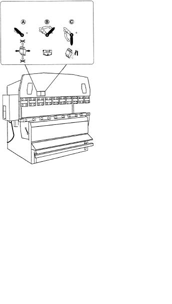
If your machine is equipped with optional one-touch punch holders, keep the following rules:
•When applying pressure to the punches or bending the worksheet, turn the punch holder levers to the position B .
ONE-TOUCH PUNCH HOLDER
LEVER POSITIONS
POSITION |
POSITION |
POSITION |
POSITIONS FOR OPERATING
LEVER AND INSTALLING AND
REMOVING PUNCHES
•Install or remove the punch holder levers only in the position B .
•Affix the punch holder lever position sticker in an easy-to-see place to prevent procedural mistakes.
i)When you bend worksheets with an assistant operator or operators, you must press the bar pedal after fully ensuring the safety of all of them.
I-4
j)Before adjusting the stoppers, turn the POWER ON/OFF keyswitch to OFF, remove the key from the keyswitch, and keep it by yourself. Be sure to adjust the stoppers from the rear of the machine.
k)Correctly set the position where the bending speed of the ram is to be changed. If this position is not correctly set, the worksheet may start to bend unexpectedly.
l)When bending a small worksheet, set the stroke length of the ram to 6 mm {0.24 in.} or less, and hold the worksheet as shown on the next page. Take care not to get your fingers pinched between the punches and dies or between the punches and worksheet.
6 mm {0.24 in.}  or less
I-5
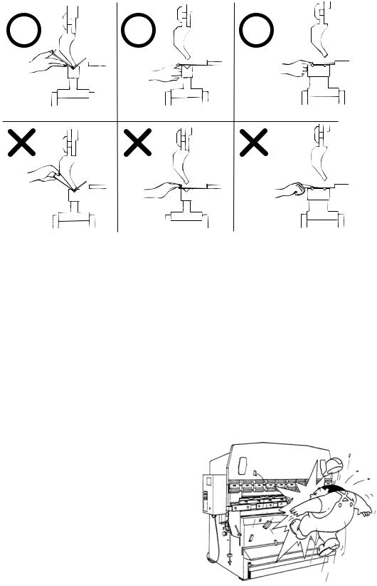
Hold the worksheet as shown below.
m)If your machine is equipped with an optional backgauge, push the worksheet against the stoppers of the backgauge after the backgauge is properly positioned. Otherwise the worksheet may be pushed forward when the backgauge moves forward.
n)Use Amada genuine punches and dies on the machine. The machine performs various controls by reference to the Amada genuine punches and dies. Non-genuine punches and dies are different in brittleness and allowable tonnage from the genuine punches and dies. Use of such nongenuine tools may cause various troubles and detract from safety of the machine.
o)Apply to the installed tools a pressure that is not higher than the allowable tonnage marked on them. Unless a proper pressure is applied to them, the tools may break and scatter in a dangerous manner.
When 2V-dies are used, use the V- groove toward the rear of the machine for additional safety from breakage.
I-6
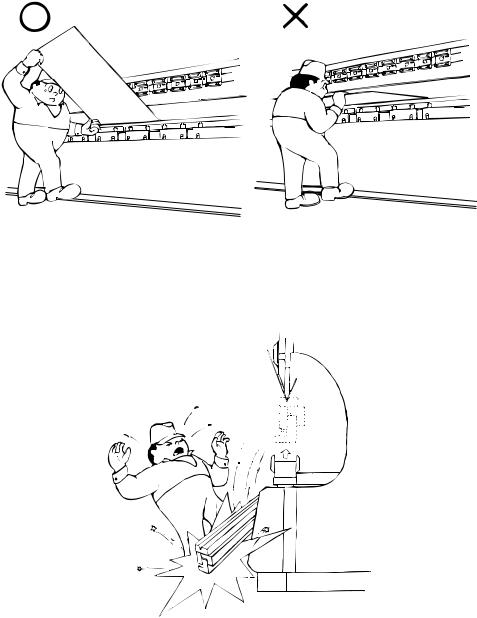
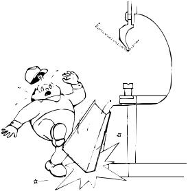
p)When bending a large worksheet, be careful of its springing upward. Hold one side of the worksheet or otherwise be ready for its springing upward.
q)Before bending each worksheet, check that the tools are securely installed and tightened. With a sharp bend or U-bend, the punches and dies may eat into the worksheet and fall together with the worksheet.
I-7

r)When rebending the same worksheet, align the nose line of the punches with the bend line of the worksheet. If the worksheet is rebent without aligning the lines, abnormal noise may be produced, and the tools may break and scatter in a dangerous manner.
s)Whenever trouble occurs during the operation of the machine, press one of the EMERGENCY STOP buttons, turn the POWER ON/OFF keyswitch to
OFF, remove the key from the keyswitch, keep it by yourself, and fix the problem. When picking a worksheet that has fallen into the machine, be sure to do so from the rear of the machine. As soon as the machine develops trouble, report it to the chief operator.
I-8
t)If the machine suddenly loses its power due to a power failure, the ram may open to the maximum opening limit. In such a case, hold the worksheet over the ram so that it does not fall.
u)Before walking away from the machine, turn the POWER ON/OFF keyswitch to OFF, remove the key from the keyswitch, and keep it by yourself.
v)Before opening the electrical enclosure, be sure to turn off the machine circuit breaker. You may receive an electric shock if you touch any parts in the electrical enclosure.
w)Be sure to perform periodic maintenance on the machine. For the items of maintenance to be performed, refer to Part VI, Maintenance.
x)Before maintaining or cleaning the machine, turn off the shop circuit breaker, relieve the residual hydraulic pressure in the machine, and post a sign to inform other workers that the machine is under maintenance.
y)When relocating the machine, ask AMADA about how to move the machine. If moved incorrectly, the machine may turn over.
I-9
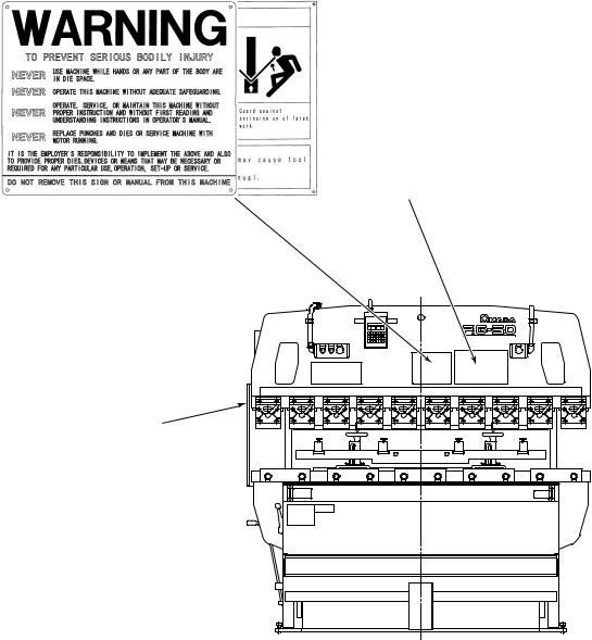
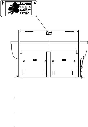
2. DANGER AND WARNING PLATES
Keep the DANGER and WARNING plates well noticeable and never remove them.
I-10
Hazard seriousness level
 DANGER
 WARNING
 CAUTION
Indicates an imminently hazardous situation which, if not avoided, will result in death or serious injury.
Indicates a potentially hazardous situation which, if not avoided, could result in death or serious injury.
Indicates a potentially hazardous situation which, if not avoided, may result in minor or moderate injury.
I-11

I-12

Part II
Description
|
|
|
1. |
....................................................................................Functions |
II-2 |
2. |
General view ............................................................................... |
II-3 |
3. |
Specifications.............................................................................. |
II-5 |
4. |
Dimensions ................................................................................. |
II-6 |
5. |
Standard accessories ................................................................. |
II-9 |
6. |
Options....................................................................................... |
II-10 |
II-1
1. FUNCTIONS
This machine is a hydraulic press brake of the central pressure application and parallel rising type. It has the following features:
•The hydraulic circuit is simplified to minimize oil leakage and facilitate maintenance.
•A main cylinder is installed at the center of the ram to minimize the distortion produced in the upper and lower beams during pressure application.
•Installed at the center of the ram, a bearing guide unit slides up and down along the main cylinder surface that doubles as sliding surface, in order to keep the upper and lower beams accurately parallel.
•A punch-to-die clearance setting unit allows the ram stroke length to be set to a required minimum and the working efficiency to be enhanced as a result.
•The bar pedal can be pressed as required to adjust the ram approach speed or stop the ram mid-stroke. This is ideal for bending worksheets on which scribed lines must be aligned with the punch nose line.
•Punch holders and die holders are installed in the upper and lower beams and provide for easy installation of punches and dies, respectively.
•Standard tools are light in mass, easy to carry, available in many types, and adaptable to a variety of bending operations. (For the tools, refer to their catalogs.)
II-2

2. GENERAL VIEW
NOTE
OThis drawing shows the general view of the RG50 machine.
EMERGENCY
STOP BUTTON
FRAME
ELECTRICAL ENCLOSURE
Power distribution and control circuits are built in. Power and hydraulic pump
motor switches are located.
Shop's main power source is connected to terminals in this enclosure.
SUPPORTER
STOPPER
HYDRAULIC |
PEDAL STOPPER |
|
|
||
EQUIPMENT CONTROLS |
|
|
Knobs and levers required for |
Pressed to allow ram to be operated |
|
operation of ram are located. |
only by single operator. Bar pedal can |
|
|
be pressed only when foot is placed on |
|
|
pedal stopper to disable pedal stopper. |
|
REAR GUARD
HYDRAULIC UNIT
Hydraulic oil tank and hydraulic drive unit are located at rear of lower beam.
EMERGENCY
STOP BUTTON
UPPER BEAM
PUNCH HOLDER
LOWER BEAM
BAR PEDAL
Pressed as required to adjust ram approach speed or stop ram mid-stroke.
II-3

II-4
3. SPECIFICATIONS
Metric unit system (International system of units)
Item |
|
|
Model |
|
|
RG35S |
RG50 |
|
RG80 |
RG100 |
|
|
|
||||
Maximum bend length (mm) |
1250 |
2085 |
|
2505 |
3100 |
|
|
|
|
|
|
Press capacity (kN) |
343 |
490 |
|
784 |
980 |
Stroke length (mm) |
100 |
100 |
|
100 |
100 |
Open height without punch holders (mm) |
370 |
370 |
|
370 |
370 |
|
|
|
|
|
|
Approach speed at 50/60 Hz (mm/sec) |
46/55 |
38/45 |
|
38/45 |
49/59 |
Bending speed at 50/60 Hz (mm/sec) |
8/9.5 |
7/8.5 |
|
7/8.5 |
8.3/10.1 |
Moving-down speed (mm/sec) |
40 |
35 |
|
52 |
52 |
|
|
|
|
|
|
Number of main cylinders |
1 |
1 (2) |
|
1 (2) |
1 (2) |
(number of auxiliary cylinders) |
|
||||
|
|
|
|
|
|
Hydraulic pump motor output (kW) |
2.2 |
3.7 |
|
5.5 |
7.5 |
|
|
|
|
|
|
Hydraulic oil tank capacity (L) |
26 |
51 |
|
51 |
65 |
Machine mass (kg) |
1600 |
2900 |
|
5100 |
6400 |
Power supply of 380/400/460 V
Item |
|
|
Model |
|
|
RG35S |
RG50 |
|
RG80 |
RG100 |
|
|
|
||||
Primary power cable (mm2) |
2 |
2 |
|
3.5 |
8 |
Load current (A) |
9.1 |
13.2 |
|
23.0 |
30.0 |
Power supply of 200/230 V
Item |
|
|
Model |
|
|
RG35S |
RG50 |
|
RG80 |
RG100 |
|
|
|
||||
Primary power cable (mm2) |
3.5 |
3.5 |
|
8 |
14 |
Load current (A) |
17.0 |
22.3 |
|
38.0 |
49.1 |
II-5
English unit system
Item |
|
Model |
|
||
RG35S |
RG50 |
RG80 |
RG100 |
||
|
|||||
Maximum bend length (in.) |
49.2 |
82.1 |
98.6 |
122.0 |
|
|
|
|
|
|
|
Press capacity (US tonf) |
38.6 |
55.1 |
88.2 |
110.2 |
|
Stroke length (in.) |
3.9 |
3.9 |
3.9 |
3.9 |
|
Open height without punch holders (in.) |
14.6 |
14.6 |
14.6 |
14.6 |
|
|
|
|
|
|
|
Approach speed at 50/60 Hz (ips) |
1.8/2.2 |
1.5/1.8 |
1.5/1.8 |
1.9/2.3 |
|
Bending speed at 50/60 Hz (ips) |
0.31/0.37 |
0.28/0.33 |
0.28/0.33 |
0.33/0.40 |
|
Moving-down speed (ips) |
1.6 |
1.4 |
2.0 |
2.0 |
|
|
|
|
|
|
|
Number of main cylinders |
1 |
1 (2) |
1 (2) |
1 (2) |
|
(number of auxiliary cylinders) |
|||||
|
|
|
|
||
Hydraulic pump motor output (HP) |
3.0 |
5.0 |
7.4 |
10.1 |
|
|
|
|
|
|
|
Hydraulic oil tank capacity (US gal) |
6.9 |
13.5 |
13.5 |
17.2 |
|
Machine mass (lb) |
3530 |
6390 |
11250 |
14110 |
|
Power supply of 380/400/460 V
Item |
|
|
Model |
|
|
RG35S |
RG50 |
|
RG80 |
RG100 |
|
|
|
||||
Primary power cable (mm2) |
2 |
2 |
|
3.5 |
8 |
Load current (A) |
9.1 |
13.2 |
|
23.0 |
30.0 |
Power supply of 200/230 V
Item |
|
|
Model |
|
|
RG35S |
RG50 |
|
RG80 |
RG100 |
|
|
|
||||
Primary power cable (mm2) |
3.5 |
3.5 |
|
8 |
14 |
Load current (A) |
17.0 |
22.3 |
|
38.0 |
49.1 |
II-6
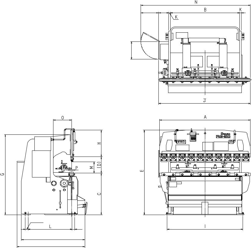
4. DIMENSIONS
390 mm 225 mm {15.4 in.} {8.9 in.}
400 mm {15.7 in.}
60 mm
{2.4 in.} 60 mm {2.4 in.}
F**
F*
*Depth of RG35S, RG50, RG80 **Depth of RG100
II-7
|
|
|
|
|
|
|
|
|
|
|
|
|
|
|
|
Unit: mm |
|
|
|
|
|
|
|
|
|
|
|
|
|
|
|
|
|
Model |
A |
B |
C |
(D) |
E |
F |
G |
H |
I |
J |
K |
L |
M |
N |
O |
P |
|
|
|
|
|
|
|
|
|
|
|
|
|
|
|
|
|
RG35S |
1200 |
1020 |
935 |
370 |
1955 |
1495 |
1800 |
650 |
920 |
1355 |
25 |
445 |
250 |
1745 |
200 |
60 |
|
|
|
|
|
|
|
|
|
|
|
|
|
|
|
|
|
RG50 |
2000 |
1520 |
940 |
370 |
1910 |
1495 |
1820 |
600 |
1670 |
2025 |
40 |
970 |
250 |
2410 |
400 |
60 |
|
|
|
|
|
|
|
|
|
|
|
|
|
|
|
|
|
RG80 |
2400 |
2050 |
945 |
370 |
2065 |
1495 |
1920 |
750 |
2240 |
2515 |
60 |
970 |
250 |
2895 |
400 |
60 |
|
|
|
|
|
|
|
|
|
|
|
|
|
|
|
|
|
RG100 |
3000 |
2550 |
1035 |
370 |
2305 |
1555 |
2110 |
900 |
2750 |
3065 |
60 |
1090 |
250 |
3445 |
400 |
90 |
|
|
|
|
|
|
|
|
|
|
|
|
|
|
|
|
|
|
|
|
|
|
|
|
|
|
|
|
|
|
|
|
|
Unit: in. |
|
|
|
|
|
|
|
|
|
|
|
|
|
|
|
|
|
Model |
A |
B |
C |
(D) |
E |
F |
G |
H |
I |
J |
K |
L |
M |
N |
O |
P |
|
|
|
|
|
|
|
|
|
|
|
|
|
|
|
|
|
RG35S |
47.2 |
40.2 |
36.8 |
14.6 |
77 |
58.9 |
70.9 |
25.6 |
36.2 |
53.3 |
0.98 |
17.5 |
9.8 |
68.7 |
7.9 |
2.4 |
|
|
|
|
|
|
|
|
|
|
|
|
|
|
|
|
|
RG50 |
78.7 |
59.8 |
37.0 |
14.6 |
75.2 |
58.9 |
71.7 |
23.6 |
65.7 |
79.7 |
1.57 |
38.2 |
9.8 |
94.9 |
15.7 |
2.4 |
|
|
|
|
|
|
|
|
|
|
|
|
|
|
|
|
|
RG80 |
94.5 |
80.7 |
37.2 |
14.6 |
81.3 |
58.9 |
75.6 |
29.5 |
88.2 |
99.0 |
2.36 |
38.2 |
9.8 |
114.0 |
15.7 |
2.4 |
|
|
|
|
|
|
|
|
|
|
|
|
|
|
|
|
|
RG100 |
118.1 |
100.4 |
40.7 |
14.6 |
90.7 |
61.2 |
83.1 |
35.4 |
108.3 |
120.7 |
2.36 |
42.9 |
9.8 |
135.6 |
15.7 |
3.5 |
|
|
|
|
|
|
|
|
|
|
|
|
|
|
|
|
|
II-8
5. STANDARD ACCESSORIES
No. |
Item |
Description |
Qty |
Applicable model |
||
|
|
Tool box |
|
|
|
|
|
|
|
|
|
|
|
|
|
Single-ended |
30 mm |
|
|
|
|
|
wrench |
13 mm |
|
|
|
|
|
45° offset box |
14 × 17 mm |
|
|
|
1 |
Tool set |
wrench |
1 |
ALL |
||
|
||||||
|
|
Allen wrench |
8 mm, long type |
|
|
|
|
|
5 mm |
|
|
||
|
|
|
|
|
||
|
|
Brass bar |
φ20 × 200 mm |
|
|
|
|
|
Hammer |
1/2 pound |
|
|
|
|
|
|
|
26 L |
RG35S |
|
|
|
|
|
{6.9 US gal} |
||
|
|
|
|
|
||
2 |
Hydraulic oil |
Super Hydraulic oil 56 (Nippon oil) |
51 L |
RG50, 80 |
||
{13.5 US gal} |
||||||
|
|
|
|
|
||
|
|
|
|
65 L |
RG100 |
|
|
|
|
|
{17.2 US gal} |
||
|
|
|
|
|
||
3 |
Stopper |
|
|
2 (0) |
ALL |
|
|
|
|
|
|
|
|
4 |
Supporter |
|
|
4 (2) |
ALL |
|
|
|
|
|
1 |
RG35S |
|
|
|
Size L: 830 mm {32.7 in.} long, |
2 |
RG50 |
||
5 |
2V-die holder |
75 mm {3.0 in.} high |
3 |
RG80 |
||
|
|
4 |
RG100 |
|||
|
|
|
|
|||
|
|
Size S: 412 mm {16.2 in.} long, |
1 |
RG35S, 50 |
||
|
|
75 mm {3.0 in.} high |
||||
|
|
|
|
|||
|
|
|
|
6 |
RG35S |
|
6 |
Punch holder |
|
|
10 |
RG50 |
|
|
|
|
|
|||
|
|
12 |
RG80 |
|||
|
|
|
|
|||
|
|
|
|
15 |
RG100 |
|
7 |
Bulb |
LS-6 |
|
2 |
ALL |
|
|
|
|
|
|
|
|
Note: Quantity values enclosed in parentheses apply when machine is equipped with optional backgauge.
II-9
6. OPTIONS
Name |
Function |
|
|
Auto-backgauge system |
• Can set worksheet contact positions (bending positions) for up |
|
to 99 processes. |
|
• Allows continuous bending by programmed operation. |
|
• Displays set values and current position of backgauge by LEDs. |
|
• Has such functions as elongation compensation, backlash |
|
compensation, and timing. |
|
|
Remote foot pedals |
• Like bar pedal, open and close ram. |
|
|
RR-type front gauge |
• Installed at front of machine to support worksheet with stoppers |
|
and used for positioning worksheet at front of machine. |
|
|
Worksheet follower |
• Supports large worksheet during bending while following bend |
|
angle. |
|
|
One-touch punch holders* |
• Allow punches to be installed and removed by levers without |
|
use of any other tool. |
|
|
Dial-type punch holders* |
• Allow height of punches to be adjusted with dials. |
|
|
Double-side punch |
• Allow punches to be installed on both of front and rear sides. |
holders* |
|
|
|
Optical safety device |
• Emits light beams at front of installed punches and dies and |
|
automatically stops machine as soon as two or more light |
|
beams are interrupted by operator’s body parts or other objects. |
|
|
Side guards |
• Close up gaps in left and right frames and prevent operator’s |
|
body parts from entering machine. |
|
|
Two-hand control buttons |
• Simultaneously pressed to open and close ram in place of bar |
|
pedal. |
|
|
Two-person foot pedals |
• Simultaneously pressed by two persons to open and close ram |
|
in place of bar pedal. |
|
|
*Standard option |
|
II-10

Part III
Installation
|
|
|
.....................................................................................1. Summary |
III-2 |
|
1-1. Environmental conditions..................................................... |
III-2 |
|
1-2. Input power source............................................................... |
III-2 |
|
1-3. Things to be supplied by customer ...................................... |
III-3 |
|
2. Installation procedures................................................................ |
III-4 |
|
2-1. Location................................................................................ |
III-4 |
|
2-2. Lifting.................................................................................... |
III-5 |
|
2-3. Foundation ........................................................................... |
III-6 |
|
2-4. |
Placing ................................................................................. |
III-6 |
2-5. |
Leveling................................................................................ |
III-6 |
2-6. |
Supplying hydraulic oil ......................................................... |
III-8 |
2-7. |
Supplying electric power ...................................................... |
III-8 |
When the machine is delivered to you directly from AMADA, it is usually transported by the specialized carrier. Instruct them where to install the machine.
Select such a machine installation place where the space required for worksheet loading, part unloading and machine maintenance can be secured and where the machine can be installed on a flat surface without ground subsidence. For details, refer to “2. Installation procedures”.
WARNING |
O Moving or carrying the machine may not only |
|
damage the machine, but also is dangerous. Ask |
||
|
||
|
a qualified contractor to perform this work. |
|
|
|
III-1

1. SUMMARY
1-1. Environmental conditions
•Keep the machine at least 10 m {33 ft} away from a welder or any other equipment that may produce electrical noise and magnetic fields.
•Where the ambient temperature is not higher than 5 °C {41 °F}, keep the machine and hydraulic pump motor energized during the day's work.
•The higher the humidity in the place where the machine is installed, the lower the insulation performance of its electric parts becomes. This results in the premature degradation of the electric parts. Do not install the machine in such a humid place.
•Install the machine in a place where it is not subjected to dust, dirt, and organic or corrosive gases.
1-2. Input power source
Power requirement: 200/230/380/400/460 VAC±10% (transformer tap and motor wiring is required), 3 phases, 50/60 Hz±1 Hz
NOTICE
OSupply the machine from a power source independent of a welder or any other equipment that may produce line voltage variations. Otherwise the machine may misoperate.
III-2
Loading...