

Page 1

NC TURRET PUNCH PRESS
ARIES 245
PROGRAMMING MANUAL
JUNE 1988
Copyright © 1998 by Amada Engineering & Service Co., Inc.
14921 East Northam Street, La Mirada, CA 90638
All rights reserved. No part of this book shall be reproduced, stored in a retrieval system, or transmitted by
any means, electronic, mechanical, photocopying, recording, or otherwise, without written permission from
the publisher. No patent liability is assumed with respect to the use of the information contained herein.
While every precaution has been taken in the preparation of this book, the publisher assumes no
responsibility for errors or omissions. Neither is any liability assumed for damages resulting from the use
of the information contained herein.
Page 2
PROGRAMMING BASICS
PROCESS FOR THE PRODUCTS
PROGRAMMING
......................................................
CALCULATION OF COORDINATES
.......................................
.....................................
..............................................
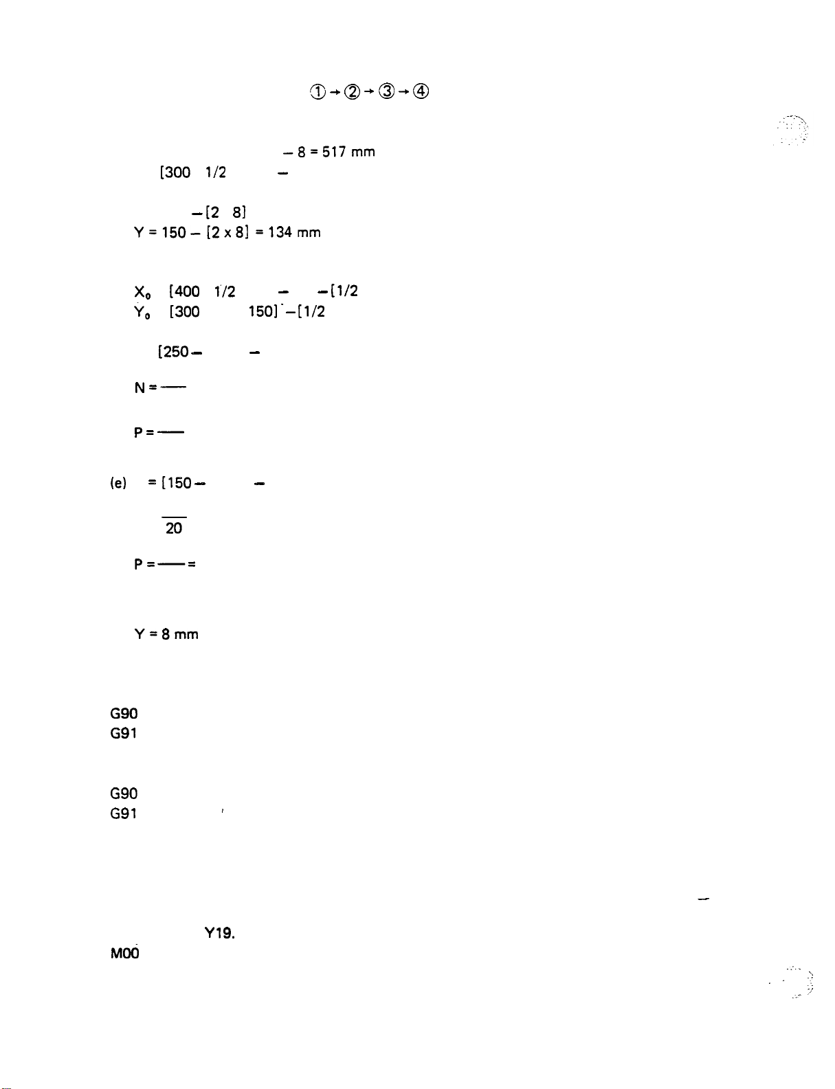
TAPE FORMAT
G92
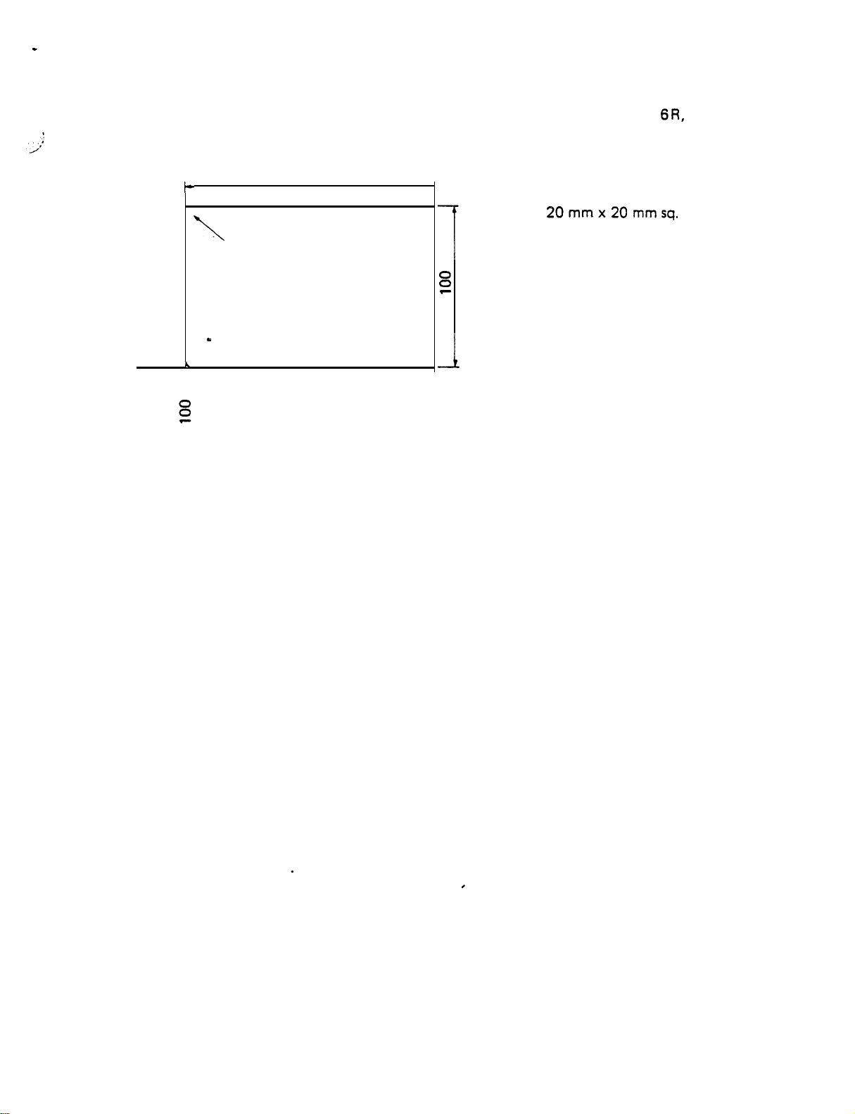
G70
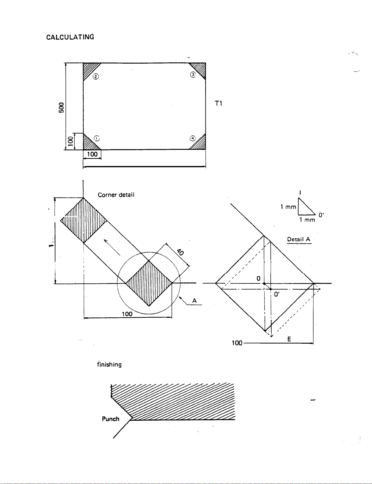
G27
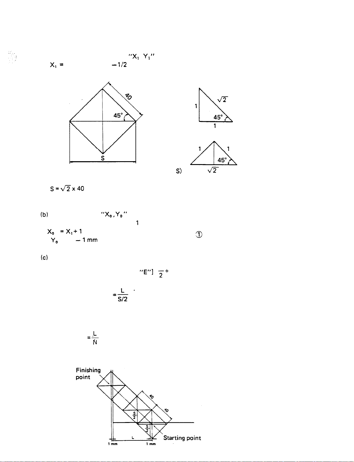
G25
G50
MOO
MO1
MO8
Ml2
TOO
NO000
PROGRAM NAME
PROGRAMMING PROCEDURE
HINTS ON PROCESSING.
CALCULATING LONG RECTANGULAR HOLE
CALCULATING LARGE RECTANGULAR OPENING
ESTABLISHING COORDINATE SYSTEM
ABSOLUTE PROGRAMMING
....................................
INCREMENTAL PROGRAMMING..
PUNCH OFF (NO PUNCHING).
AUTO REPOSITIONING
AUTO REPOSITIONING
HOME
........................................
........................................
............................................
..................................
...........................
...............
. ...
........
PROGRAM STOP.. .............................................
OPTIONAL STOP..
PUNCH DELAY START, MO9
START, Ml3
DESIGNATION OF TOOL NUMBER..
SEQUENCE NUMBER
DESIGNATION OF AXIS FEED SPEED
............................................
PUNCH DELAY CANCEL.
NIBBLING CANCEL
...................
.........
.........................
......................................
............................
........................................
.........................................
.......................
.................
...........................
.......................
CALCULATING RECTANGULAR OPENING WITH ROUNDED CORNERS
CALCULATING 45” NOTCH
HINTS ON PROGRAMMING
HINTS ON AUTO REPOSITIONING
...........................................
...........................................
.....................................
.....
l-l
1-2
l-3
l-4
4
l-4
l-5
l-5
1-6
l-7
1-7
l-8
-1-8
1-8
l-9
9
l-9
1-15
1-17
1-19
l-22
1-25
1-26
Page 3
G72
G22
G28
G26
G36
G66
G67
G68
G69
G78
G79
DESIGNATION OF PATTERN ORIGIN
LINE AT DISTANCE
............................................
LINE AT
ARC
SQUARE
NIBBLING ARC
.......................................................
BOLT HOLE CIRCLE
GRID-X, G37
SHEAR PROOF
................................................
..........................................
................
.............................
NIBBLING LINE
PUNCHING ARC
PUNCHING
...............................................
...............................................
.......................
PATTERN MEMORY AND PATTERN RECALL
G93
MACRO FUNCTION
G73
G77
BLOCK DELETION
INPUT OF DECIMAL POINT
ROTATION
..................................................
.
...................................................
...........................................
............................
...............
.....
...
.........
...........................
2-l
2-2
3
..2- 5
2-7
9
2-11
2-15
2-17
2-19
2-22
4
2-26
0
1
2-32
2-32
MULTIPLE PART PUNCHING
GENERAL DESCRIPTION AND PROGRAMMING EXAMPLE . . . . . . . . . . .
G98
UOO TO VOO
G75, G76 WOO
SETTING OF REFERENCE POINT AND LAYOUT FOR
MULTIPLE PART PUNCHING
OF PART PROGRAM . .
RECALLING AND EXECUTION OF
. . . . . . . . . . . . . . . .
. . . . . . .
PART PROGRAM . . . . . . . . . . . . . . . . . . . . . . . . .
TRIAL PUNC HING, POST-T R IAL PUNC HIN G, AND FULL PUNCHING . . . . . . .3-14
CLAMP DEAD ZONE
HOW TO
DEAD ZONE
ZONE DIAGRAM
................................................
DEAD ZONE DIAGRAMS
..............
................................
...............................
. . . 3-l
. . . 3-8
.3-10
4-2
4-3
(APPENDIX) PROGRAMMING EXAMPLE
,
GENERAL PUNCHING
EX. 2 PUNCHING WITH AUTO REPOSITIONING
EX.3 MULTIPLE PART PUNCHING
......
.....................................
.......................
.....................................
5-6
5-11
(APPENDIX) DISPLAYED FORMAT ON CRT.. . . . . . . . . . . . . . . . . . . . . . . . . . . . 6-l
Page 4
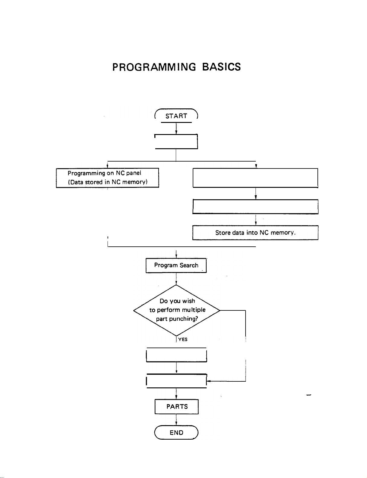
PROCESS FROM DIAGRAM TO PARTS
Diagram
.
Programming on AMACOM programming
system (Data stored
Set floppy disk in ARIES FDD.
in floppy disk)
Input Set Up Data
r
Push Start Button
NO
Page 5
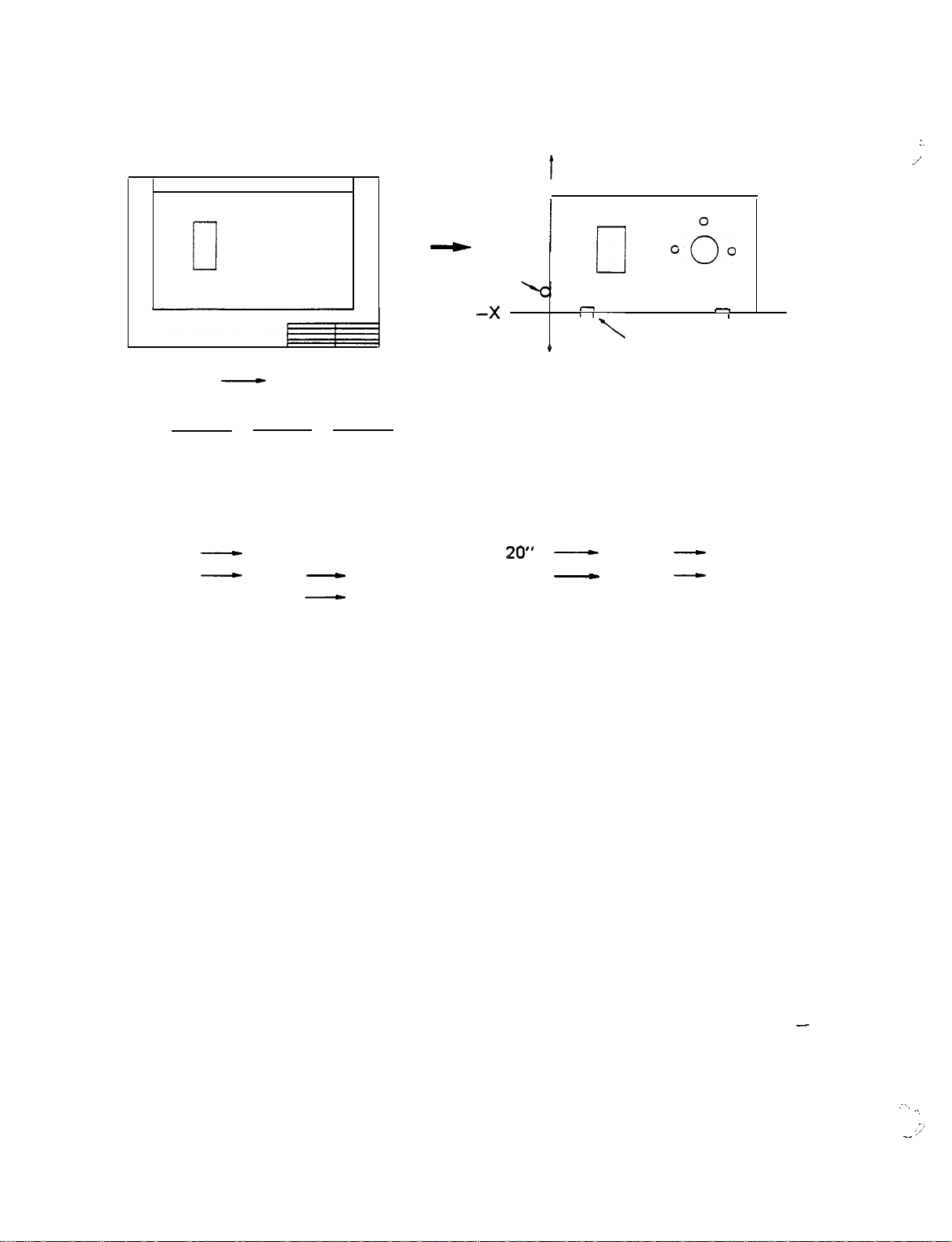
PROGRAMMING
0
Y
-Y
Work clamp
Calculations
20.000~
2.700
Diagram
0
0
1. Diagram
2. Calculation of coordinates
3. x
UNIT OF MEASUREMENT FOR PROGRAMS
All dimensions for programs are based on units-of 0.01 mm (millimeters) or 0.001” (inches).
100 mm
35.5 mm
Omm
-0
First quadrant of X and Y coordinate system
Y
Calculations
100.00 -100.
35.50
0
0
0
T
Program
35.5 2.7”
0 0” -0
X-gauge block
First quadrant
0
I
Program
20.
2.7
-0
X
l-2
Page 6
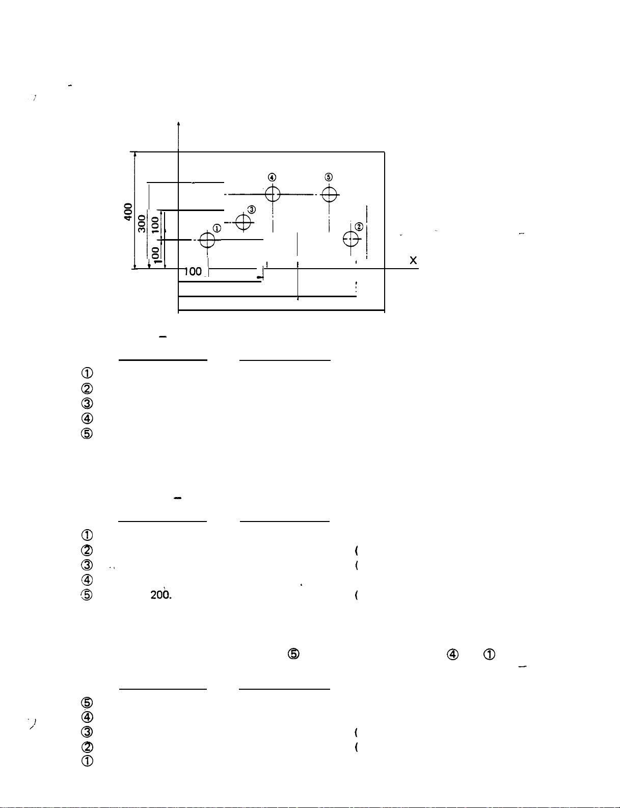
CALCULATION OF COORDINATES
Y
Absolute value
X coordinate value
100.
300.
300.
400.
600.
Incremental value
X coordinate value
0
Distance from origin
200
400
Distance from previous position
I
700
Y coordinate value
100.
100.
200.
300.
300.
Y coordinate value
200
100.
200.
‘I 0
100.
(In the case of zero, no decimals are needed.)
Problem: Calculate the absolute value of
X coordinate value
. .
Y coordinate value
100.
100.
100.
(Absolute value)
0
and the incremental value of
Incremental value)
Incremental value)
(Incremental value)
Incremental value)
(Absolute value)
(Incremental value)
Incremental value)
Incremental value)
(Incremental value)
thru
.
Page 7
BASIC FUNCTION CODES
“G” function (Preparatory function)
MOO
TOO
NO000
“M” function (Miscellaneous function)
“T” function (Tool function)
Sequence number
FORMAT
Arrange the function codes as follows:
NO000
TOO MOO
NOTE: a) Unnecessary codes need not be entered.
Enter only necessary digits of X, Y and N.
The plus sign
of X and Y can be omitted.
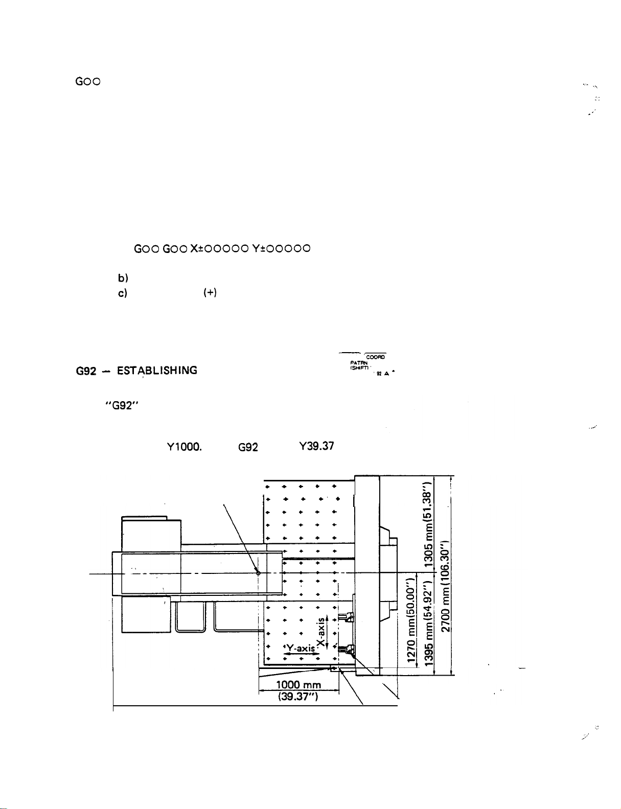
COORDINATE SYSTEM
--
This code is used to. designate the distance from the worksheet origin
Enter
and the distances in the X- and Y-axis direction.
to the punch center.
Metric-specification machine
G92 X1270.
Punch center,
X-gauge block-
Inch-specification machine
X50.
3784 mm
(148.98”)
\
“Work clamp
l-4
‘Worksheet origin
Page 8
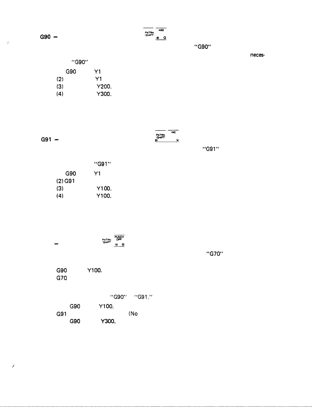
ABSOLUTE PROGRAMMING
When the absolute values are used for coordinate values, enter
prior to the coordinate
values. If the absolute values are used at the subsequent blocks of the program, it is not
sary to enter
Ex.: (1) G90 X100.
again until incremental values are used.
00. T2 (Absolute value)
x300.
x300.
x400.
00.
(Absolute value)
(Absolute value)
(Absolute value)
The value of the X- or Y-axis which does not move can be omitted.
INCREMENTAL PROGRAMMING
When the incremental values are used for coordinate values, enter
prior to the coordinate values. If the incremental values are used at the subsequent blocks of the program, it is
not necessary to enter
Ex.:
(1) G90 Xl 00.
X200. Y 0
x 0
X100. YlOO.
again until absolute values are used.
00. T2 (Absolute value)
(Incremental value)
(Incremental value)
(Incremental value)
The value of the X- or Y-axis which does not move can be omitted.
G70
PUNCH OFF
This code is used to move the worksheet without punching. Enter
. X-Y-.
Ex.: G90 X100. YlOO. T2
X300. (The axes move at a position of “X300. Y 100.” without
,
“G70” can be entered with
punching.)
or
Ex.: G90 X100. YlOO. T2 (Punching)
G70 X200.
(Punching) ,
prior to entering
Page 9
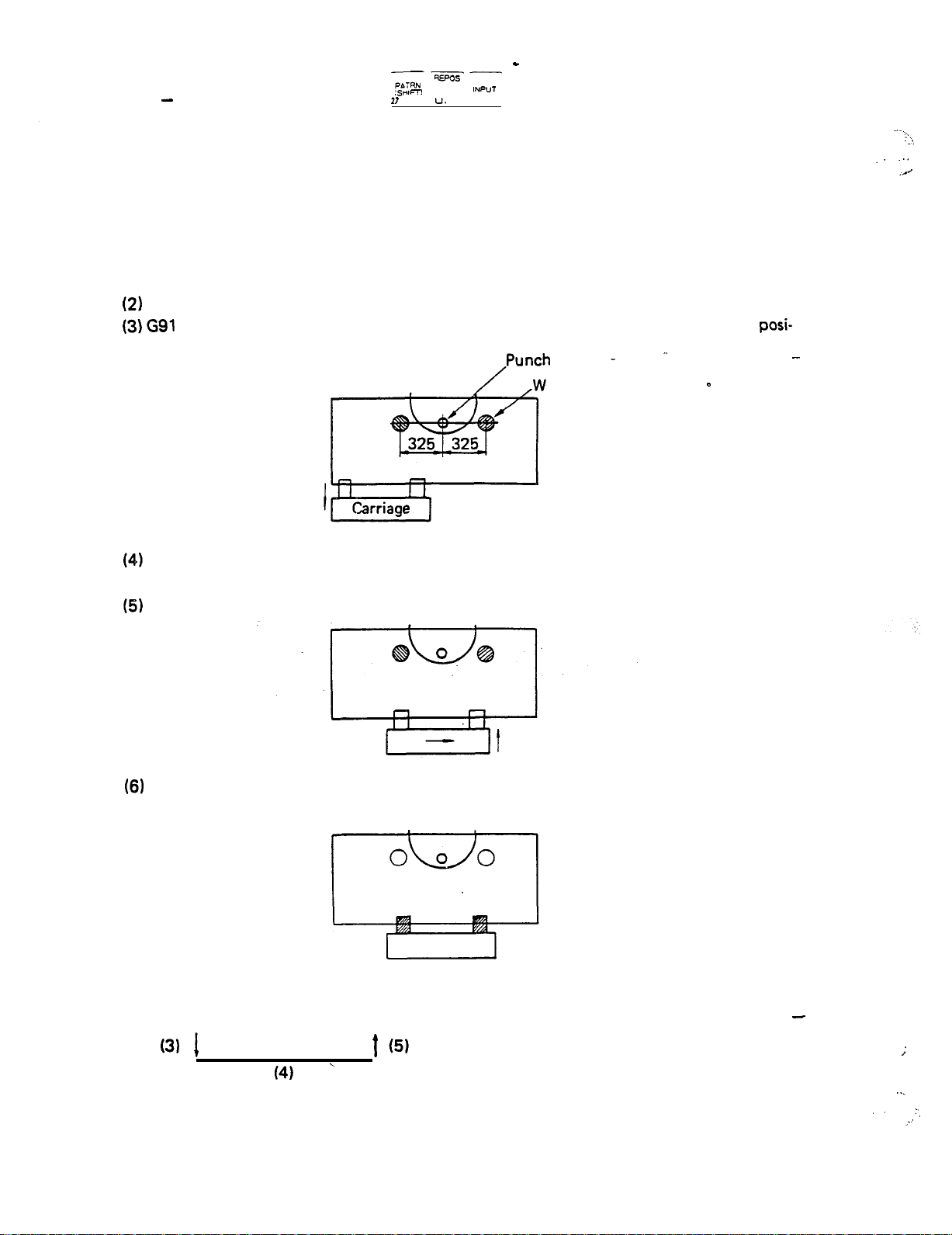
G27
AUTO REPOSITIONING
.
This code is used to extend the punching range in the X-axis direction. Enter “G27” and
the X-axis value.
G27 X500.
Ex.:
The X-axis value must be designated by an incremental value.
.
The following shows the repositioning cycle for a G27 X500. command.
(1) Work hold:
Unclamp:
Y2.4:
x-500.:
Y-2.4:
The work holders hold the worksheet.
The clamps open.
The table moves 2.4 mm in the positive direction from the current
tion.
center
ork holder
The carriage moves 500 mm in the negative direction from the current
position1
The table moves 2.4 mm in the negative direction.
Clamp:
(7) Work release:
The clamps close.
The work holders release the worksheet.
Table and Carriage movement
2.4 mm
500 mm
2.4 mm
l-6
Page 10
AUTO REPOSITIONING
u:
When the worksheet edge which is clamped has a bend, curves or excessive burrs, enter
“G25” instead of “G27” to ensure accurate repositioning. These factors can cause inaccurate
worksheet positioning when automatic repositioning is performed, unless the G25 code is
used. When
is read, the same movement will be obtained as in the following:
2.4 mm
1.2 mm
G25 X
First the table moves 2.4 mm in the positive direction from the current position. Then the
carriage moves
from the current position and the table moves 1.2 mm in the negative
direction. Next, the X and Y coordinate system is offset by Y1.2 to compensate for the
difference between the table positions before and after the automatic repositioning.
After “G25” is read, the punching range along the Y-axis is moved 1.2 mm in the negative
direction from the standard punching range.
-11.4 to 1009.0 mm (-0.448” to 39.724”)
G50
When
HOME RETRACT
is read, the carriage and table return to their origins. No punching occurs during
the retraction. The offset values designated by
a,nd “G98” are cancelled. “G50” must
be entered as a single block; however, the sequence number can be entered along with it.
Page 11
MOO
Enter “MOO” if a program stop is desired.
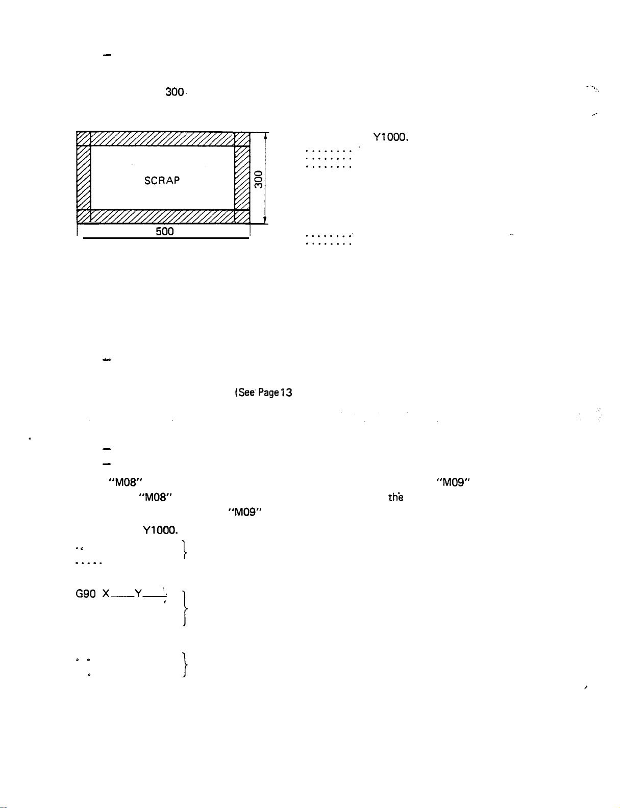
Ex.:
When “MOO” is read, the machine stops. When the START button is pressed after the scrap
has been removed, the machine will continue the punching operation. “MOO” must be en.
tered as a single block; however, the sequence number can be entered with it.
PROGRAM STOP
Punching a 300. mm x 500 mm rectangular opening with a 50 mm x 50 mm square
punch.
G92 X1270.
Y42.
Y42.
Y42.
500
MOO (Machine stops here)
MO1
This code has the same function as “MOO”; however, the machine will stop only when the
OPTIONAL STOP key is lighted.
MO8
MO9
When
is read. Use
than 4.5 mm (0.18”). “M08” and
G92 X1270.
MO8
. . . . .
. . . . .
MO9
.
. .
G50
OPTIONAL STOP
PUNCH DELAY START
PUNCH DELAY CANCEL
is read, the hit rate is changed from standard to low until
. . .
. .
. .
of the OPER’ATOR’S MANUAL.)
.
or “G50”
when the sum of worksheet thickness and the formed height is more
must be entered as a single block, respectively.
Standard hit rate
J
Low hit rate
Standard hit rate
l-8
Page 12
Ml2
Ml3
NIBBLING START
NIBBLING CANCEL
When
is always engaged with the brake released.
is read, nibbling is performed until
is read. In nibbling, the press clutch
and “Ml 3” must be entered as a single
block, respectively. Pattern punching cannot be commanded between Ml 2 and Ml 3.
Ml2
X-
691
Nibbling [Hole intervals should be 6 mm (0.236”) or less.]
J
Ml3
TOO
DESIGNATION OF TOOL NUMBER
This code is used to designate the tool station number in order to select the tool to be used.
If the same tool is to be used continuously, it is not necessary to enter this code again until a
different tool is needed.
Ex.:
X1270.
T2
X50.00
not required)
x50.00
T3
NO000
Any numeral (from 1 to
SEQUENCE NUMBER
with four or less digits, beginning with “N” can be entered
at the beginning of each block. This code is used for indexing each block.
Ex.:
NO001 G90 X450.
NO002
NO003
NO004 G90 X500.
X1270.
X50.
x50.
T2
,
T3
The sequence number need not be entered if it is not necessary. Entry at
instead of all blocks will be useful.
Zeros which directly follow “N” may be omitted.
Page 13
FO
DESIGNATION OF AXIS FEED SPEED
axis feed speed can be changed by this code. The axis feed speed is decreased as the value
following “F” is changed from 1 to 4 (1
the
buttons located on the NC control panel. When there is the difference
between instructions by this code and the
2
3
4). This code has the same function as
buttons, the priority will be given to
the slower axis feed speed. The instruction of the “F” code is held until a new “F” code is
read or the RESET button is pressed. When
is read, when the EMERGENCY STOP
button is pressed, or when the power source is turned off, the instruction value of the “F”
code automatically becomes “4”;
F2
F3
F4
PROGRAM NAME
Enter the program name at the top of the program for the identification of individual ones.
The name must be within 8 alphabets or-numeral characters and only the alphabet letter can
be used for the first character of the name.
Ex.: ARIES 1
G92 Xl 270.
G50
This program name can also be input and changed from the NC control panel.
l-10
Page 14

PROGRAMMING PROCEDURE
1. Determining the processing method
2. Determining the clamp position
Position the clamps as far apart as possible and check the “dead zone” (see the DEAD
ZONE DIAGRAMS).
Checking the tool and station number
3.
Ex.:
(a) Check to ensure the proper tool is used for the cut-out required.
150 mm dia. round hole
300
x 400 mm square opening
-nibbling with a 20 mm
-shear-proof punching with a 50 mm x
punch
50 mm square punch
(b) Check to ensure desired tools can be loaded into the turret.
Problem: Is the combined use of the following tools for one program possible?
50 mm dia., 35 mm dia., 80 mm.dia., 20 mm x 20 mm sq., and 30 mm dia.
(2” dia., 1.4” dia., 3” dia., 0.8” x 0.8” sq., and 1.25” dia.)
4. Determining the punching sequence
This must be determined by taking into consideration both the processing time and
accuracy.
General precaution
(a) Begin and finish with the upper right corner of the diagram.
(b) Begin with small holes, then square openings, and notching.
(c) The tools should not be selected -more than’ twice.
(d) In multiple part punching, shearing of the worksheet should be done last.
5. Calculating the coordinates
Calculate the coordinate values in units of 0.01 mm (millimeters) or 0.001” (inches).
6. Checking.
Check the clamp positions, punching sequence and coordinate values.
Page 15
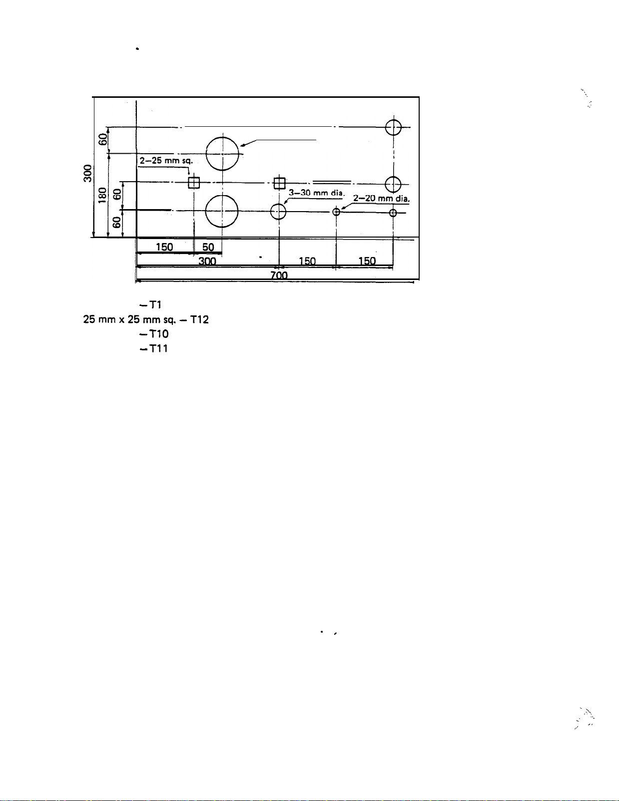
Problem: Program the following diagram. (Enter the sequence No.)
2-60 mm dia.
60 mm dia.
30 mm dia.
20 mm dia.
(Thick turret with Auto-Index)
111
1-12
Page 16
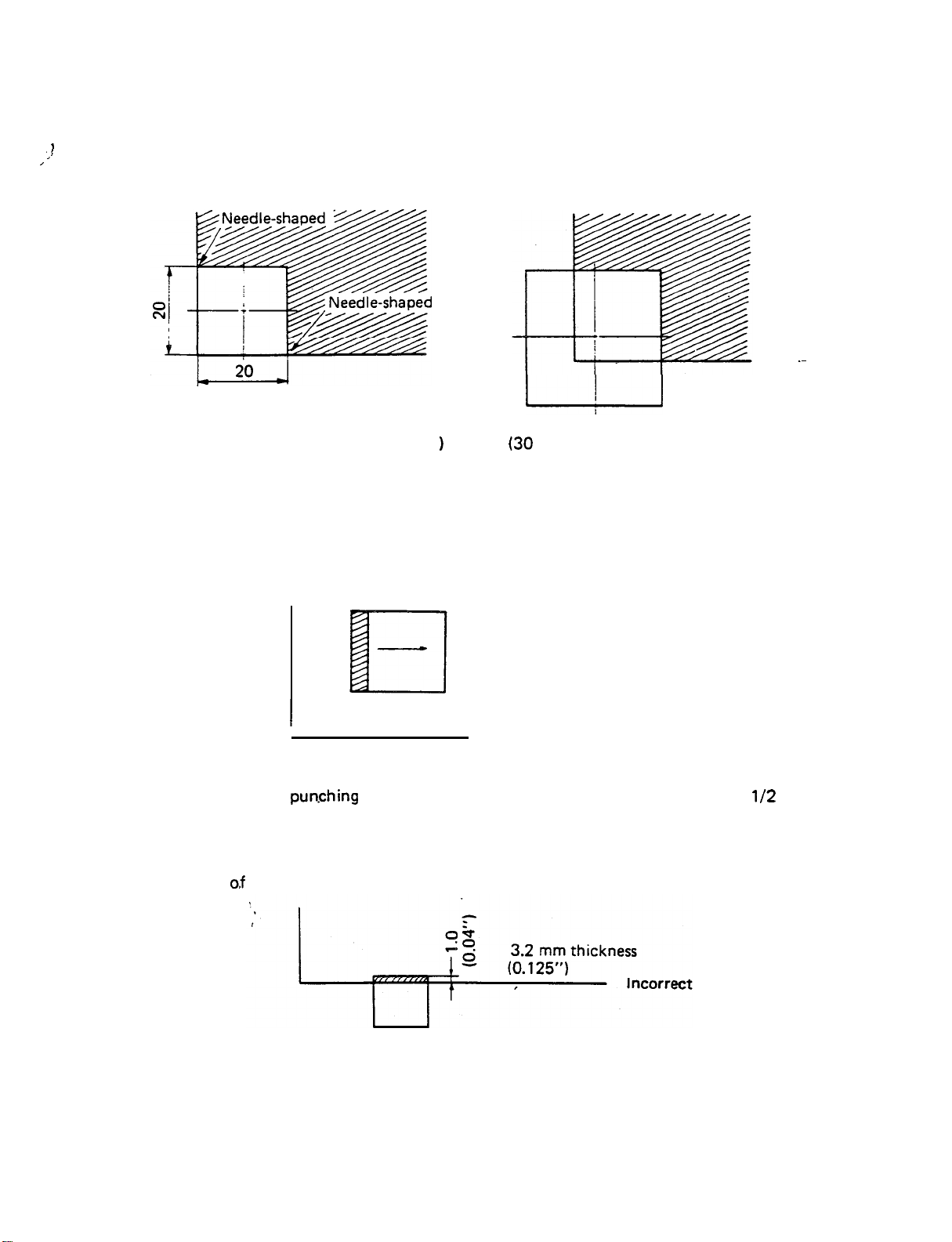
HINTS ON PROCESSING
1.
Notching should not be performed with a punch of the same size as the notch.
Incorrect
Correct
(20 mm x 20 mm square punch is used.
Problem: Prepare a program to punch out
a 20 mm x 20 mm sq. notch with a 15 mm x 15
mm sq. punch.
2.
Do not punch along the shorter punch side when using a long rectangular punch.
Incorrect
3. When shear-proof
is performed, the feed pitch should be larger than
punch width, but smaller than the entire punch width minus 0.5 mm (0.02”).
the
4.
The depth
notching should not be less than the plate thickness.
Page 17
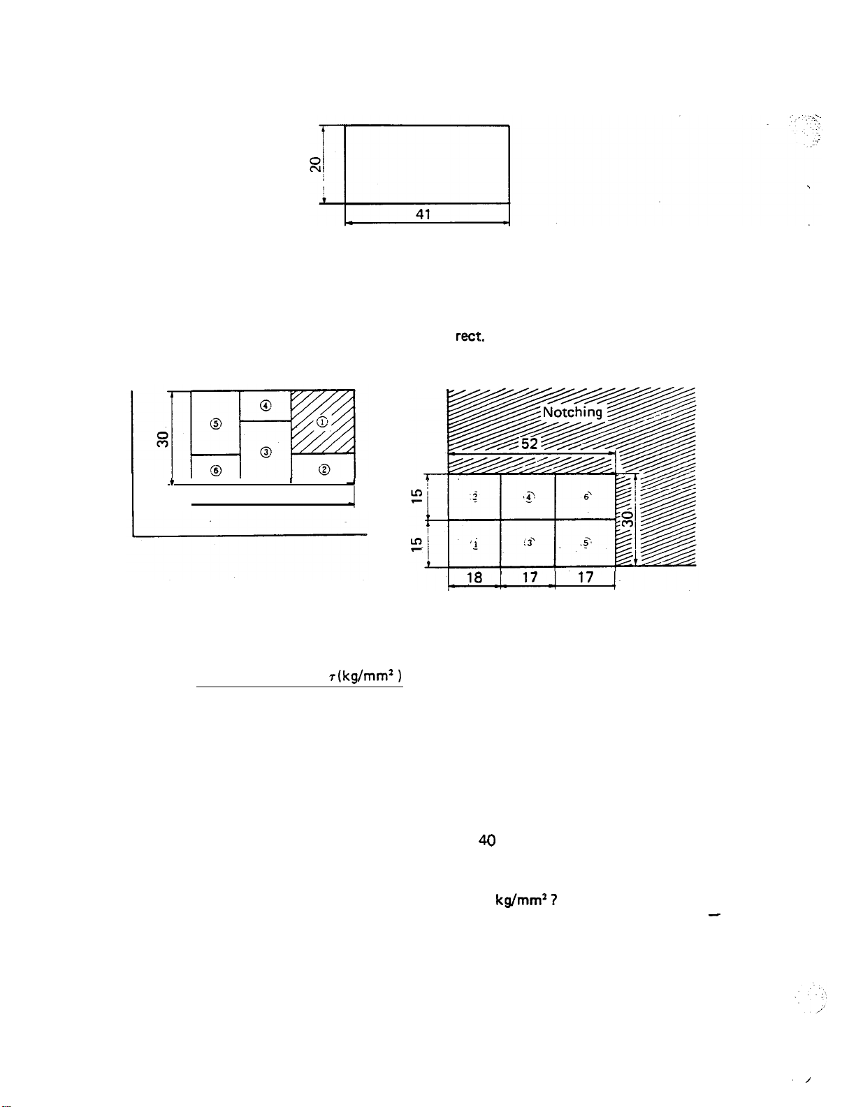
Problem: Determine the method for punching a 20 mm x 41 mm rectangular hole with a
20 mm x 20 mm sq. punch.
5.
Determine the punching method so that the stripper plate holds the worksheet as much
as possible.-
Method for punching a 30 mm x 52 mm rect. hole with a 20 mm x 20 mm sq.
Ex.:
punch.
I
I
52
6.
The force required to punch the worksheet must not exceed the machine capacity.
The required punching force is obtained by the following formula:
P (ton) =
A (mm) x t (mm) x
1000
where, P: Force required
A: Length of cut edge
t: Thickness of worksheet
I: Shearing strength of worksheet
Problem: Is it possible to punch holes with a diameter of 40 mm in a mild steel plate with a
thickness of 3.2 mm and a shearing strength of 46 kg/mm’ ?
Problem: Is it possible to punch a 20 mm x 20 mm square hole in a stainless steel plate with
a thickness of 3 mm and a shearing strength of 60 kg/mm5?
1-14
Page 18
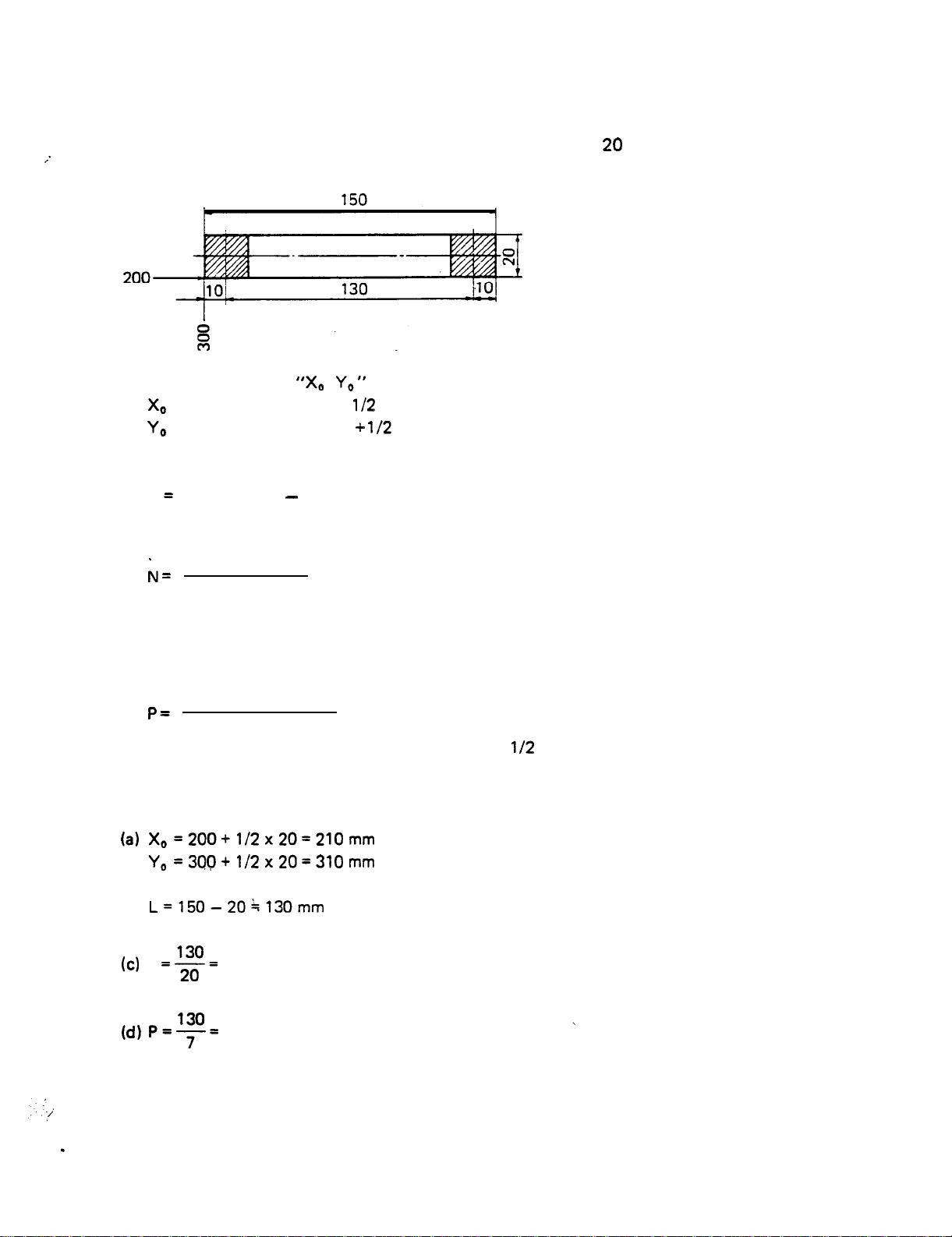
CALCULATING LONG RECTANGULAR HOLE
When punching a 20 mm x 150 mm rectangular hole with a
Ex.:
(Punching begins with the left side of the hole)
(a) First punch position
= [X value at left end] +
= [Y value at lower end] c
(b) Travel distance “L”
L
[Total length]
(c) Punching frequency “N”
[Travel distance]
[Punch width]
[Punch width]
,
(Absolute value)
[Punch length along X-axis]
[Punch length along Y-axis]
When decimal numbers are obtained
Ex.: 6.2 -7
When integral numbers are obtained
Ex.: 9-10
mm x 20 mm sq. punch
(d) Feed pitch “P”
[Travel distance]
= [Punching frequency]
NOTE: The value of “P” should be larger than
the entire punch width minus 0.5 mm.
(b)
N
-7 times
6.5
18.57 mm
the punch width, but smaller than
Page 19
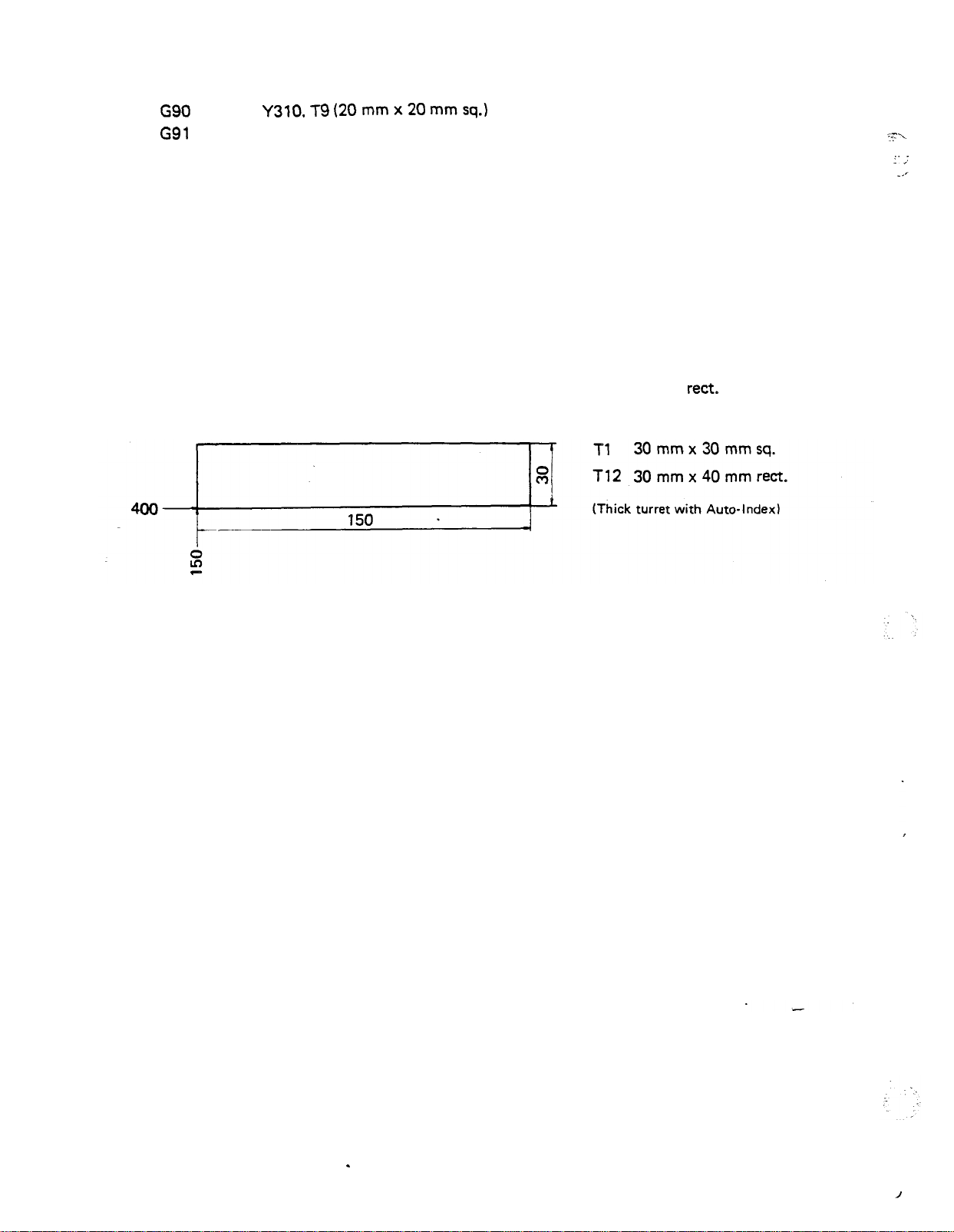
Therefore the program is:
X
T9
18.57
X 18.57
X 18.57
X 18.57
X 18.57
X 18.57
X 18.57
Problem: Punch a 30 mm x 150 mm rectangular hole with a 30 mm x 30 mm sq. punch.
Problem: Punch a 30 mm x 150 mm rectangular hole with a 30 mm x 40 mm rect. punch.
1-16
Page 20
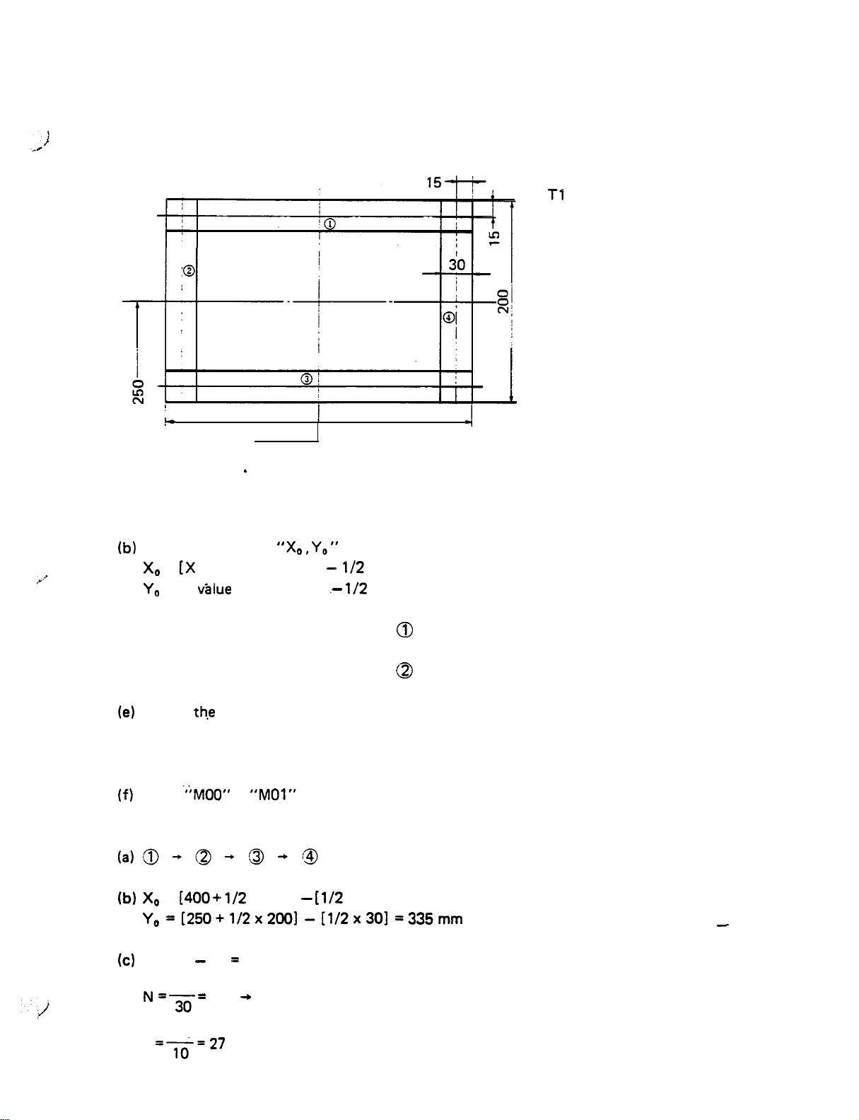
CALCULATING LARGE RECTANGULAR OPENING
When punching a 200 mm x 300 mm rectangular opening with a 30 mm x 30 mm sq.
Ex.:
punch
300
400
(a) Punching procedure
Finish punching at the upper right corner in order to remove the scrap easily,
30 mm x 30 mm sq.
(Absolute value)
=
value at right end]
= [Y
at upper end]
[Punch length along X-axis]
[Punch length along Y-axis]
(c) Punching frequency and feed pitch of
(d) Punching frequency and feed pitch of
Prepare
program in accordance with the punching sequence.
NOTE: Do not punch the final punch position because the last punch fails on the first
punch position.
or
=
x 3001
in order to remove the scrap.
x 301 = 535 mm’
L = 300
27Ci
270
P
30
9.0
270 mm
10 times
mm
Page 21
(d)
170
=--5.6
30
170
6
170mm
6times
28.33
mm
Therefore the program is:
X-27.
Y-28.33 (6 times)
X27.
Y28.33
MOO
(30 mm x 30
(10 times)
(10 times)
times)
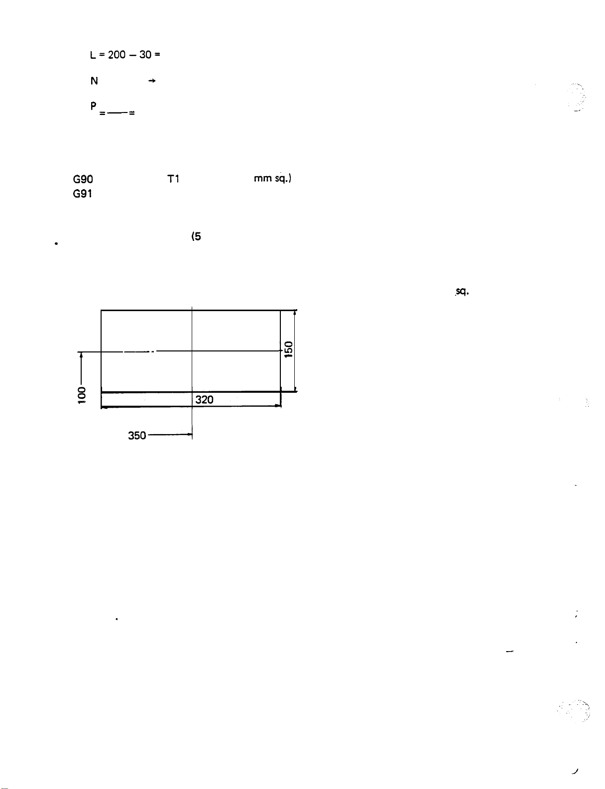
Problem: Punch a 150 mm x 320 mm rectangular opening with a 20 mm x 20 mm
T18 20 mm x 20 mm sq.
I .
(Thick turret with Auto-Index)
punch.
1-18
Page 22
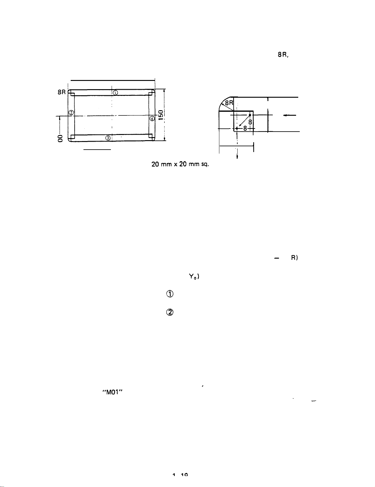
CALCULATING RECTANGULAR OPENING WITH ROUNDED CORNERS
When punching a 150 mm x 250 mm opening with rounded corners of 8R, using a
Ex.:
16 mm dia. round punch and a 20 mm x 20 mm square punch
t-
250
o
400
T16 16 mm dia.
T18
(Thick turret with Auto-Index)
(a) Punching procedure
First, punch 4 corners of 8R with 16 mm dia. round punch.
Finish punching at the upper right corner.
(b) Punching positions for 4 corners.
Punching position for one corner
Punching positions for other corners
-Absolute value
-Incremental value (Opening length
Finishing point
Starting. point
2 x
(c) First punch position with a square punch (X,,
-Absolute value
(d) Punching frequency and feed pitch of
(e) Punching frequency and feed pitch of
(f) Travel distance from the finishing point on one side to the starting point on another side
-Incremental value
X value: Radius
Y value: Radius
(g) Prepare the program in accordance with punching procedures.
(h) Enter “MOO” or
in order to remove the scrap.
Page 23
(a) 4 corners and then 83
(b) Absolute value (upper right corner)
X= [400+1/2x2501
Y =
+
x 1501
8 = 367 mm
Incremental value
X = 250 x
= 234 mm
(c) Position of the first square punching
=
=
+
x 250
+ 1/2x
81
x 201 = 365 mm
x 201 = 507 mm
(d) L =
214
214
L
N
114
2 x 81
= 10.7
20
= 19.45 mm
11
2 x 81
114
= 5.7 -6 times
=
19 mm
6
20 = 214 mm
-11 times
(f) X = 8 mm
Therefore the program is:
Y367. T16 (16 mm dia.)
X-234.
Y-l 34.
X234: ,
Y365. T18 (20 mm x 20 mm sq.)
X-19.45
X-8. Y-8.
Y-19.
X8. Y-8.
x19.45
X8. Y8.
20 =
(11 times)
(6 times)
(11 times)
(6 times)
114 mm
l-20
Page 24
Problem: Punch a 100 mm x 150 mm rectangular opening with rounded corners of 6R, using
a 12 mm dia. round punch and a 20 mm x 20 mm square punch.
150
T2 12 mm dia.
l
T18
450
6R
,
I
(Thick turret with Auto-Index)
Page 25
45” NOTCH
When punching 45” notches in 4 corners of a 500 mm x 600 mm plate
Ex.:
600
40 mm x 40 mm sq. (45”)
0
! ullllllllll
0
0
The starting and
sure accurate notching.
,
points of notching should be shifted about 1 mm in order to en-
l-22
Page 26
Notching the lower left corner
(a) Provisional starting point (0)
[Notch size “E”]
Y, =o
(Diagonal punch size:
= 1.414 x 40 = 56.56 mm
Starting point (0’)
Shift both X and Y axes about
mm
(In case of the lower left corner
= Y,
, (Absolute value)
[Punch size]
(Absolute value)
mm from (0).
)
Punching frequency and feed pitch
.
s
Travel distance L = [Notch size
Punching frequency N
-
2 x 1 mm
When decimal numbers are obtained
Ex.: 2.3 -3
When integral numbers are obtained
,
Feed pitch P
NOTE: The feed pitches of the X- and Y-axes should be equal and should be larger than
Ex.: 3-4
S/4, but smaller than S/2 minus 0.5 mm (0.02”).
,
Page 27
= 100
=Omm
= 71.72 + 1 = 72.72 mm
L
= 100
N
x 56.56 = 71.72 mm
= -1 .OO mm
28.28 + 2 = 73.72
74
= 2.62 -3 times
P
Therefore the program is:
X-24.67 Y24.67
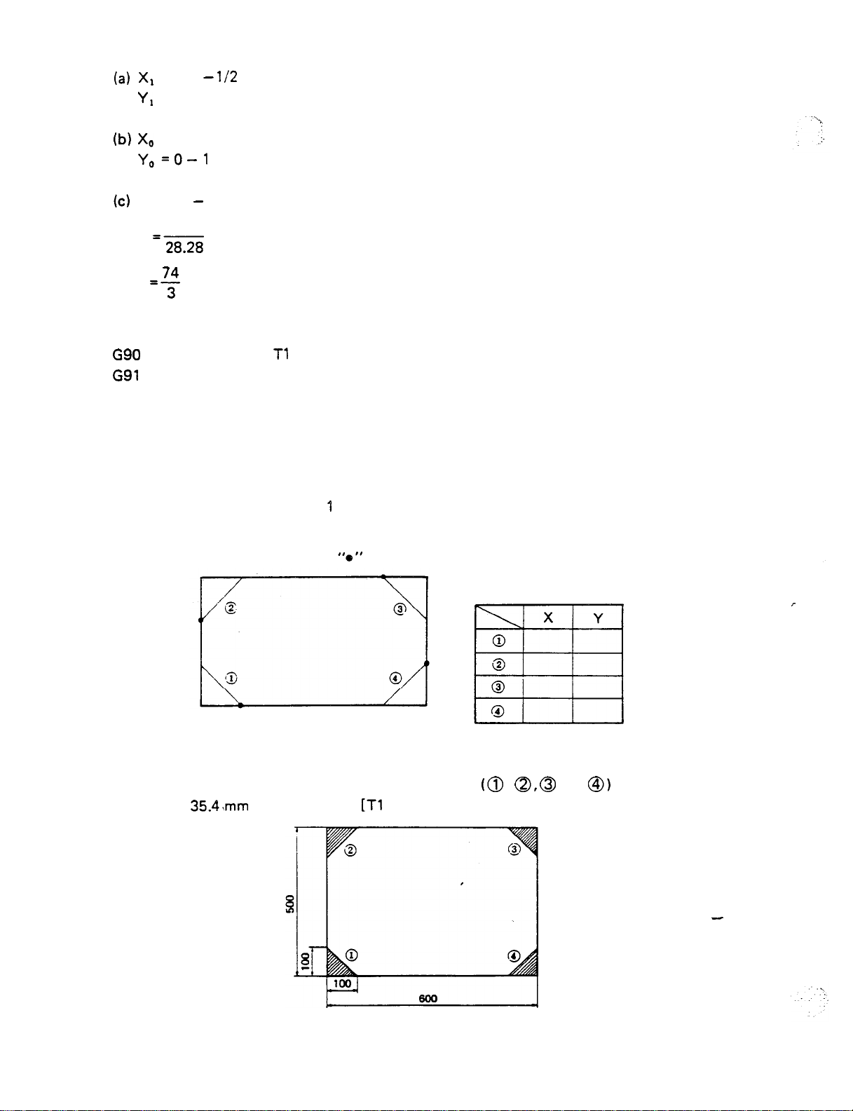
Problem: Calculate “S” of a 30 mm x 30 mm sq. 45” punch, and of a 50 mm x 50 mm sq.
Problem: What will the sign of
= 24.67 mm
(40 mm x 40 mm sq. 45”)
(3 times)
45” punch.
mm be when calculating the starting point (0’) for each
corner?
mark means starting points.
Problem: Prepare the program for notching all corners
x
sq. (45”) punch
I.
1-24
,
and
with a 35.4 mm
Page 28
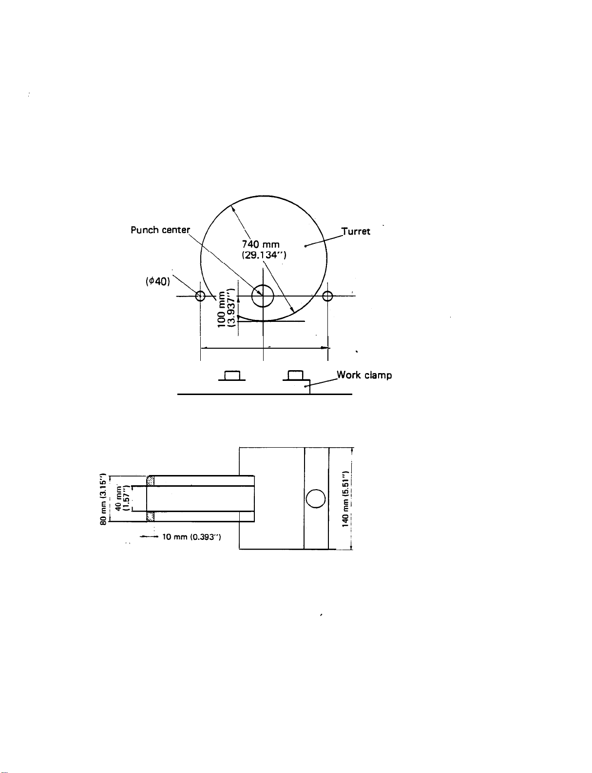
HINTS ON PROGRAMMING
1. PUNCHING RANGE
Punching range common
X-axis:
Y-axis:
-10.2 mm to 1280.2 mm (metric), -0.401” to 50.401” (imperial)
-10.2 mm to 1010.2 mm (metric), -0.401” to 39.771” (imperial)
to
all stations
2. POSITION OF WORKHOLDERS
Work holder
325 mm
(12.795”) (12.795”)
I
325 mm
1 I
3. WORK CLAMP DIMENSIONS
Page 29
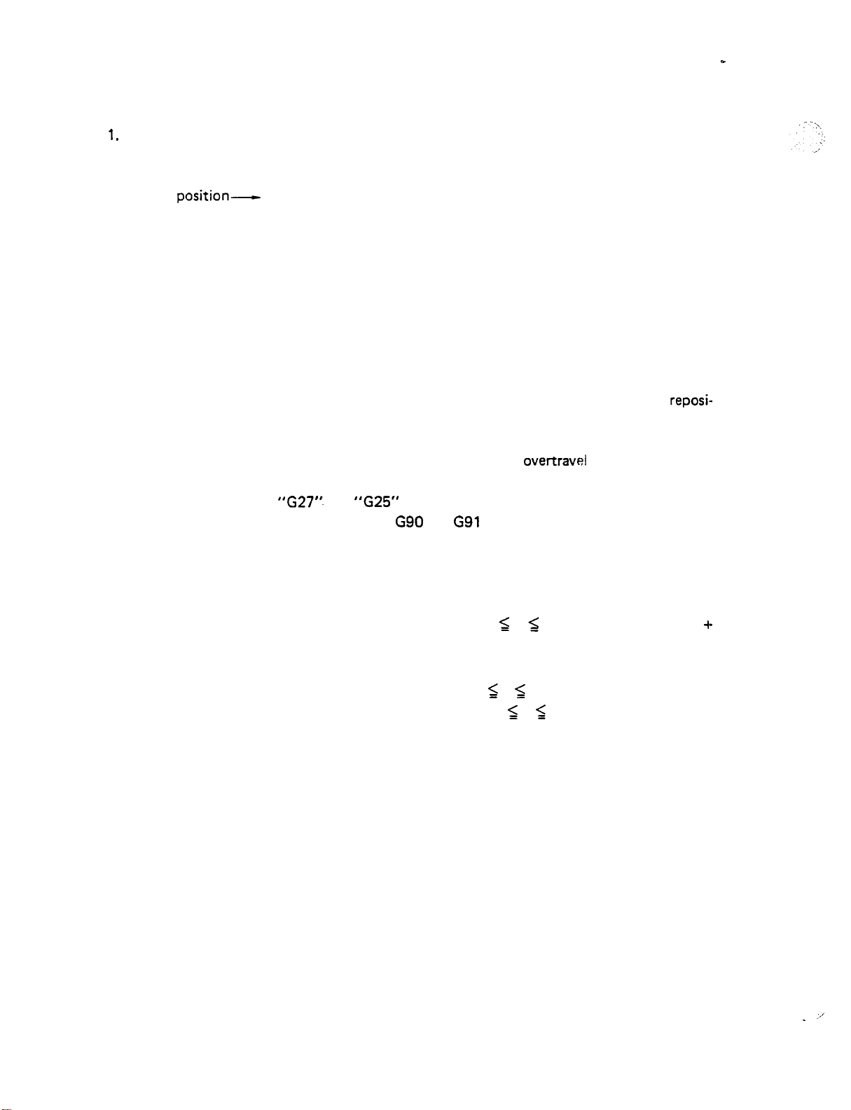
HINTS ON AUTO REPOSITIONING
Repositioning travel distance -as small as possible
[Maximum processing position (X value)] -1280 mm (50.393”)
2. Clamp
as far apart as possible
Consider the following:
l Dead zone
l Worksheet size
l Notches
3. First processing area
-as large as possible
4. Reposition
(a) Ensure the worksheet is under the work holders.
(b) Ensure the clamps do not pass between the upper and lower turrets when the
tioning is done. Y 100.00 mm (min.)
(c) Ensure the X-axis absolute value is greater than the repositioning travel distance.
If it is not greater than the repositioning travel distance, overtravel will occur.
5.
Coordinate value after
Use dimensions as per diagram. Mode of G90 and
6.
Avoid changing tools immediately after repositioning to save processing time.
and
does not change.
7.
Processing area after auto repositioning
-10.2 mm (-0.401”) + repositioning travel distance
repositioning travel distance.
G27 X500. (X20.000)
Ex.:
Processing area after auto repositioning = 489.8
(19.283”
X
1280.2 mm (50.401”) +
X
1780.2 mm
X
70.086”)
1-26
,.’
Page 30
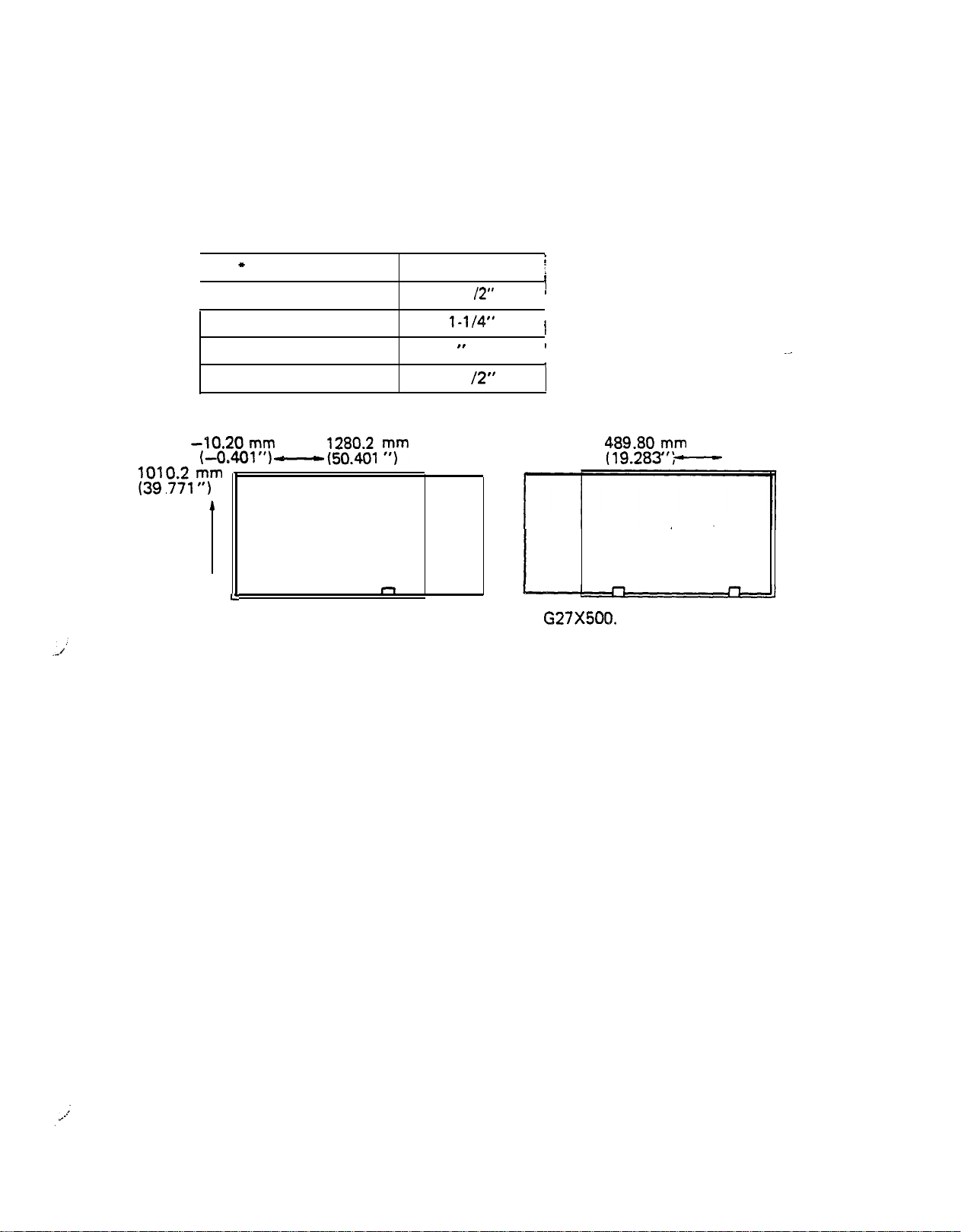
NOTE: When the repositioning detector switch has been turned to ON, the repositioning
light will be lighted and a pause is made for confirmation before auto repositioning
provided the programmed Y-axis value is less than the specified value*. In this case
be sure to check to ensure that there is no interference between the work holders
and work clamps before pressing start button.
I
Specified value
I
40 mm (1.57”)
60 mm (2.36”)
Tool type
1
I
y-f1 ‘;?;”
.
1
-10.20 mm
(-0.401”)
60 mm (2.36”)
110 mm (4.33”)
Travel area
i-l
Before repositioning
2
3-l
After
(X20.000) repositioning
Travel area
1780.2 mm
(70.086”)
Page 31

SOFTWARE
G72
G72 X
This code is used to designate the pattern origin.
Ex.:
The pattern origin can be entered both as an absolute value and as an incremental value.
“G72” merely selects a coordinate; neither positioning nor punching is performed.
Never enter the M or T code in a block with
For example, never enter:
G72 X150.
If an incremental value of X and Y is given after a pattern command, the value must refer
to the final pattern point.
OF PATTERN ORIGIN
T2
MOO
Page 32

G22
LINE AT DISTANCE
.
Starting from either the current position or from a point designated by
are punched with a punch of diameter
X-coordinate of the final pattern point,
x:
Y-coordinate of the final pattern point,
Y:
Compensation for punching length at the final pattern point,
J:
Final pattern point
Final pattern point +
Punch diameter,
P:
when
when
The hole is punched at the left of the line of travel when
The hole is punched on the line
The hole is punched at the right of the line of travel when
at a pitch of “d” -to the final position (x, y).
0
< 0
> 0
when
= 0
0
Feed pitch, “d”
Final pattern point
.
the holes
G72 X0
X140.00
When
(Incremental) is placed before G22, the final pattern point (x,
J6.00 P20.00 QlO.OO T9
in incremental values referenced to the pattern origin.
G72
G22
J6.00 P20.00 Q1O.OO T9
2-2
can be specified
Page 33

G28
LINE AT ANGLE
,
Starting from either the current position or from a point designated by
are punched with a pitch of “d” at an angle of
I: Pitch “t
When “d” is negative, the punching is performed in the opposite direc-
to the X-axis.
“n” holes
tion from that of positive “d”.
J: Angle
K: Number of holes
NOTE:
Example:
Counterclockwise
Clockwise
negative
positive
(excluding the point of the pattern origin)
“d” and “6” are given as follows:
d 200 mm
45”
200.
45.5
45.
6 holes
10 mm dia.
Pattern origin
5.)
Initial
300
.
Pattern origin
8
G28
J30. K6 T2
When punching the same hole at the pattern origin
in the upper instruction block.
When “125.” becomes
punching is performed in the direction of 180” symmetry
).
10 mm dia: T2
(X300.,
punch
point
omit “G72” and enter
Page 34

Problem:
Problem:
7 holes
4 holes
5 mm dia.
10 mm dia.
mm dia.: T2
5 mm dia.: T5
2-4
Page 35

G29
ARC
On the circumference of a circle having a radius
point designated by
as the center,
holes with an angle increment of
punched, starting from a point at an angle of “8
Radius “r”
I:
J: Start angle
positive
Counterclockwise
Clockwise
negative
K: Number of holes “n”
P: Angle increment
Counterclockwise
Clockwise
negative
Example:
Final
“r” with either the current position or a
are
to the X-axis.
positive
positive
10 mm dia.: T2
Final
pattern
-Pattern origin
G29
80. J30. K6
T2
When punching the same hole at the pattern origin (X380., Y120.1, omit
“T2” in the upper’instruction block.
When “P15.” becomes “P-l
with the starting point.
punching is performed in a clockwise direction beginning
,
and enter
Page 36

Problem:
525-
1
5 holes
20 mm dia.
20 mm dia.:
(Thick turret with Auto-Index)
Problem:
20 m
125
5 holes
20 mm dia.
20 mm dia.:
(Thick turret with Auto-Index)
2-6
Page 37

G26
On the circumference of a circle having a radius
point designated by “G72” as the center,
BOLT HOLE CIRCLE
“r” with either the current position or a
holes dividing the circumference into “n”
equal parts are punched, beginning with a point at an angle of
I: Radius “r”
J: Start angle
K: Number of holes
positive
Counterclockwise
Clockwise
Counterclockwise
Clockwise
positive
negative
positive
negative
Example:
to the X-axis.
6 holes
mm dia.: T2
10 mm dia.
X300.
180. J45. K6 T2
When punching the same hole at the pattern origin
in the upper instruction block.
The final pattern point coincides with the pattern origin.
omit “G72” and enter
Page 38

Problem: Punch four 20 mm dia. holes using code G26, then punch two 20 mm dia. holes
using an incremental instruction.
mm dia. bolt hole circle
270
4 holes
20 mm dia.
I 50 L
2 holes
20 mm dia.:
(Thick turret with Auto-Index)
20 mm dia.
2-8
Page 39

G36
GRID-X
G37
GRID-Y
from either the current position or from a point designated by
of “n,
spaces with a pitch of
parallel to the Y-axis is punched.
parallel to the X-axis and
G36: Punching starts from the X-axis side.
G37: Punching
Pitch X
P:
spaces
J: Pitch
K:
spaces “n2
from the Y-axis side.
+X direction
-X direction
direction
direction
positive
negative
positive
negative
Example:
23 holes
spaces
10 mm dia.
10 mm dia.: T2
a grid pattern
a pitch of
Initial
--
Initial punch
Final pattern point
G36 150. P3 J-20. K5 T2
G37 150. P3 J-20. K5 T2
When punching the same hole at the pattern origin
in the upper instruction block.
Final pattern point
Final punch
i
t
X350.
Y440.1, omit “G72” and enter
Page 40

Problem: Program the following using codes G36 and G37. Indicate their respective final
punches.
Problem:
24 holes
14 mm dia.
14 mm dia.: T16
(Thick turret with Auto-Index)
mm x
mm sq.:
2-10
Page 41

G66
PROOF
u
Starting from either
with a length of
the current position or from a point designated by
2d” and a punch width of
to the X-axis.
I: Length
J: Angle
Tool length
K: Width
If K
Counterclockwise
Clockwise
(punch width in the “J” direction)
(punch width in the direction of 90” to
negative
(Punching length in the direction of 90” to “J”)
Q, “K can be omitted.
D: Micro joint compensation value
If d = 0, d” can be omitted.
The values of
When a square punch is used
The sign of “w,
and
must have the same sign.
), “Q
and
x
positive
(in relation to punching length)
can be omitted.
a shear proof
is performed at an angle of
Example
1:
G72 X350.
G66 1120. J45.
0
DO.1 5 T8
Pattern origin
pattern pdint
punch
--- When
20 mm x 20 mm sq.
(Thick turret with Auto-index)
T8
Page 42

When “G72” is omitted and
is entered in the upper instruction block, the pattern
origin (X350., Y210.) is also punched.
When
becomes “P-20.“,
a shear proof is performed in the direction of the dotted
line.
I (length
must be at least 1.5 times as large as P (tool length
The final pattern point does not coincide with the final punch center.
When “D0.15” becomes “D-0.15”, the overall punching length “I” is 0.3 mm shorter as
determined by 0.15 x 2
0.3.
Example 2:
When “P” is negative
Pattern origin
20 mm x 20 mm sq. (30”):
(Thick turret with Auto-Index)
G66 180.
When
origin (X200.,
When
is omitted and
becomes
K50.
is also punched.
a shear proof is performed in the direction of the dotted
is entered in the upper instruction block, the pattern
line.
(length
must be at least 1.5 times as large as P (tool length
K (width “P,“) must be at least 1.5 times as large as P (tool length
The final pattern point does not coincide with the final punch center.
Square punch (w,
) must be used when K (width
is entered.
=
Problem:
7
6 mm x 60 mm Rect.:
2-12
Page 43

SQUARE
Starting from either the current position or from a point
opening with a length of
Y-axis is punched, using a square punch with a width of “w”.
I: Opening length in the X-axis direction
J: Opening length in the Y-axis direction
Tool length in the X-axis direction
NOTE: As a square punch is normally used on programming G67 function, “Q” is often
omitted.
Example:
parallel to the X-axis and a length of “P,” parallel to the
+X direction
direction
direction
direction
Pattern origin
Final pattern point
240
(positive value only)
560
by
positive
negative
positive
negative
a rectangular
T9
G67 I-240. J-120.
MOO
When “G72” is omitted and
origin
When “G67”
Both I and J
length
is also punched.
“MOO” or
X
T9
is entered in the upper instruction block, the pattern
should be entered in order to remove the scrap.
and Y
must be at least three times as large as P (tool
Page 44

Problem:
200
I
350
50 mm x 50 mm sq.:
2-14
Page 45

G68
NIBBLING ARC
On the circumference of a circle having a radius
“r” with either the current position or a
point designated by “G72” as the center, a nibbling with a pitch of “d” is performed by
using a punch with a diameter of
and moving up to an incremental angle of “0
I: Radius “r”
J: Start angle
positive value
Counterclockwise
Clockwise
K:
Moving angle in which nibbling occurs
Counterclockwise
Clockwise
P: Tool diameter
starting from a point at an angle of “0 to the X-axis
positive
negative
positive
negative
Enter the positive value when nibbling the outer side
of the circle and the negative value when nibbling the
inner side.
Q: Nibbling pitch
Worksheet thickness < d
positive value only
6 mm (0.236”)
NOTE: Maximum worksheet thickness for nibbling: 3.2 mm (0.125”)
Example:
Final pattern point
Final punch
,
G68 160. 530.
When
origin (X300.,
10. P-25.
is omitted and
is also punched.
25 mm dia.:
turret with Auto-index)
Initial punch
,
is entered in the upper instruction block, the pattern
Page 46

When the value of “P” is zero, nibbling is performed on the arc with the radius
Example:
When nibbling a worksheet with a thickness of more than 3.2 mm
(ARC) or G78 (PUNCHING ARC).
When the scrap remains inside, make “J” (start angle
or
in order to remove the scrap.
90” or 45”
Problem:
20 mm dia.: T9
use code G29
enter “MOO”
Problem
Program the following using NBL-A (G68) and SHP (G66).
20 mm dia.: T9
2-16
mm
Page 47

NIBBLING LINE
Starting from either the current position or from a point designated by
with a pitch of “d” and a length of
I-
a
at an angle of “0” to the X-axis is performed using
a punch with a diameter of
Length “P” (from the initial punch center to the final punch center)
Angle
J:
Tool diameter
P:
Counterclockwise
Clockwise
negative
positive
When the value is positive, nibbling is performed on the left
side of the straight line (on the hatched side in the figure);
when it is negative, nibbling is performed on the right side
of the straight line.
Nibbling pitch “d”
Q:
Worksheet thickness
positive value only
d
6 mm
NOTE: Maximum worksheet thickness for nibbling: 3.2 mm
Example:
-0
25 mm dia.:
(Thick turret with Auto-index)
Pattern origin
Y 120.
G69 1180.
If
(X300.,
If P
is omitted and
120.) is also punched.
0, the initial punch center coincides with the pattern origin.
P25.
is entered in the upper instruction block, the pattern origin
,
When nibbling a worksheet with a thickness of more than 3.2 mm
(LINE AT ANGLE) or G79 (PUNCHING LINE).
use code G23
Page 48

Problem:
Problem :
25 mm dia.:
Pitch: 4 mm
25 mm dia.:
Pitch: 5 mm
(Thick turret with
Auto-Index)
(Thick turret with
Auto-Index)
2-18
Page 49

G78
On the circumference of a circle having a radius
PUNCHING ARC
-“r” with either the current position or a
point designated by “G72” as the center, a punching which is the same as the NIBBLING
ARC (G68) is performed by turning the clutch on and off at a pitch of “d”, using a tool
with a diameter of
to an incremental angle of “0
starting from a point at an angle of “0 to the X-axis and moving up
I: Radius “r”
J: Start angle
Angle in which punching occurs
P: Tool diameter
positive value
0,
Counterclockwise
Clockwise
negative
positive
Counterclockwise
Clockwise
negative
positive
Enter the positive value when punching the outer side of the circle and the negative value
when punching the inner side.
Q: Nibbling pitch “d”
positive value only
Worksheet thickness < d
D: Worksheet thickness
is larger than the value of “d” (t > d), it is regarded as a
gram error.
Example:
Final pattern point
Final punch
,
G78 1100.
When
origin
is omitted and “T18” is entered in the upper instruction block, the
10. P-30. Q6. D4.5 T18
is also punched.
30 mm dia.:
(Thick turret with Auto-Index)
Page 50

When the value of “P” is zero, punching is performed on the arc with the radius
Example:
When the scrap remains inside, enter “MOO” or
in order to remove the scrap,
2-20
Page 51

Starting from either the current position or from a point designated by
a punching
which is the same as the NIBBLING LINE (G69) is performed by turning the clutch on and
off at a pitch of
using a punch with a diameter of “@“, in the length of “P” at an angle
of “0” to the X-axis.
I: Length “P” (from the initial punch center to the final punch center)
P: Tool diameter
Counterclockwise
Clockwise
negative
positive
.
When the value is positive, punching is performed on the left side of the straight line (on
the hatched side in the figure); when it is negative, punching is performed on the right
side of thestraight line. Refer to the NIBBLING LINE (G69) on page 2-17.
Q: Nibbling pitch “d”
Worksheet thickness
positive value only
d
D: Worksheet thickness “t”
NOTE: When
is larger than “d” d), it is regarded as a program error.
Example:
Final
punch
Initial punch
300
G79 1210. J25.
If
(X300..
If P
is omitted and “T18” is entered in the
is also punched.
0, the initial punch center coincides with the pattern origin.
Q6. D4.5 T18
Final pattern point
30 mm dia.: T18
(Thick turret with Auto-Index)
instruction block, the pattern
Page 52

PATTERN MEMORY AND PATTERN RECALL
When a pattern instructed by the codes G26, G28, G29, G36, G37, G66, G67, G68, G69,
quired. To memorize a pattern, enter the address letter “A” along with a one-digit numeral
(from 1 to 5). To recall the pattern, enter the address letter “B” and the same one-digit
numeral as that was used by “A”.
Example:
dia.
Al G26 1125. J60. K6 T2
750
[Pattern memory]
mm dia.:
T2
G72 X750.
[Pattern recall
should always be entered at the front of the pattern command block;
must be
entered as a single block by itself. “AO” and “BO” are only used for the pattern memory
and recall. Memorization and recalling of a coordinate value are impossible with these.
2-22
Page 53
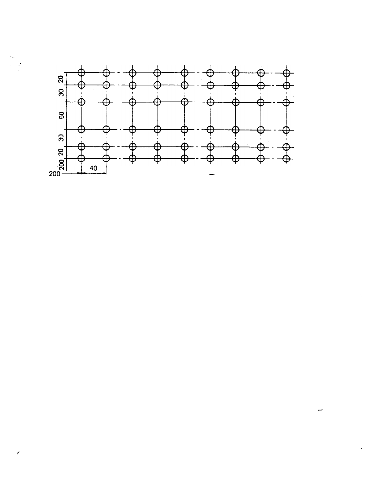
Problem: Program the following with “AO”, “BO” and “G28”.
54 holes
10 mm dia.: T2
10 mm dia.
Page 54

OFFSET
G90 G93 X
G93 X
---------- ------ ________
-Y-I
This code designates the origin of the local coordinate system.
Example:
600
Punch
center
X and Y coordinate system:
X’ and Y’ coordinate system:
X” and
coordinate system:
Basic coordinate system (Global coordinate system)
Local coordinate system
Local coordinate system
When designating the X’ and Y’ coordinate system
When designating the X” and
or,
coordinate system
G93 Xl 50. -Y50.
Method of designating point A
G90 X300.
T2
G90 G93 X50. Y75.
X250.
T2
G90 G93 X50. Y75.
G93 X200. Y125. (or
T2
G93 X150.
When changing from the local coordinate system to the global coordinate system
2-24
Page 55

The
code is merely for establishing a coordinate system;
tioning or punching, Do not enter “T” or “M” with
Example: G90 G93 X50. Y 100. T2
Program error
Basic format of a program using
G92
X1270.
Y
X
Y
G50
is not to be used for posi-
Page 56

Memory ,
voo
WOO . . . Recall
Macro storing
Using the macro function, the contents of multiple blocks of data can be stored within the
memory of NC as a single macro data; and this stored data can be recalled whenever required,
To store multiple blocks of data, enter the address letter
from “01 to 99” as a single block, preceding the multiple blocks which you wish to memorize, and enter the address letter
address letter “U” as a single block, after the multiple blocks which you wish to memorize.
using the same two-digit numeral as was used for
along with a two-digit numeral
The
number comes in the following three types:
59:
60
89:
90
99:
2. Macro
The multiple blocks of data which were stored by “U” and
dress letter “W” with the same
numeral following “U” or ‘“V” is called the “macro number”. This macro
The blocks of data between “U” and
taneously being executed.
The blocks of data between “U” and “V” are only stored into the memory.
Storing of multiple macros is accomplished.
numeral that was used at ‘“U” and “V”.
remain
they are simul-
can be recalled by the ad-
2-26
Page 57

3. Example
G92 X1270.
uo2
G72 X150.
Al G66 1100. JO
G72 X450.
vo2
T8
These instructions remain stored while they are
simultaneously being executed.
I
G37 18. P3
G28 125. J-90. K6
wo2
. . . . . .
. . . . . .
.
These instructions are merely stored.
I
Recalling and processing of instructions stored be-
tween U02 and V02
Recalling and processing of instructions stored be-
tween U70 and
Page 58

4. Multiple recalling of macro
The data which was stored as macro data can
be stored and then be recalled again.
Example: U05
. . . . . . . . . .
. . . . ..a...
vo5
wo5
. . . . .
recalled, and the recalled data can also
be
In the above example, the execution is carried out
This multiple recalling is possible up to triple level.
5.
The maximum memory capacity for macro is 8000 characters. One character equals:
(1) One letter
(2) One numeral
(3) One symbol (EOB, etc.)
The delete, space, and other codes which are ignored by the NC are not considered as
characters.
wo5
for macro (Macro numbers 01 to 89)
X, Y, T, M, etc.)
. . . . . .
in the following manner.
2-28
Page 59

6.
Storing and recalling of multiple macros
Multiple macros can be stored and recalled by using the macro numbers 90 to 99. These
macro numbers are only capable of defining a group of multiple macros as one macro,
and they are unable to store execution instructions.
Example: U90
X100.
uo2
vo2
. . .
-This block is not stored.
=
w15
wo2
The maximum number of macros that can be stored by each of the macro numbers 90 to
99 is 15.
7. Macro memory setting
When the following occurs, all macro data stored in memory will be cancelled:
(a) When the NC power is turned off
(b) When the RESET button is pressed
(c) When
However, the macro data stored in memory can be retained under conditions (a) to (c)
above by setting the NC through the control panel. For this setting procedure, refer to
instructions under the “NC setup data” on Page 22 of the OPERATOR’S MANUAL.
command is executed
.
Page 60

G73
SYMMETRY
The specified pattern stored by the macro number “m”
is symmetrically mapped with a
median line of length “a” or “b” from the reference point in the X-axis or Y-axis direction
as the axis of symmetry designated by
and is punched in the symmetrical position.
X: Distance from the reference point of the specified pattern to the reference point of the
symmetrical pattern in the X-axis direction, “a”
Y: Distance from the reference point of the specified pattern to the reference point of the
symmetrical pattern in the Y-axis direction, “b”
Numbers for the axis of symmetry,
n =
1:
Position of the specified pattern
n=
Position of the symmetrical pattern with the axis of symmetry parallel to the
2:
Y-axis and centered on X = a/2
n =
3:
Position of the symmetrical pattern with the axis of symmetry parallel to the
X-axis and centered on Y =
n=
4:
Position of the symmetrical pattern with the axis of symmetry centered on X =
al2 and Y =
Example:
I
---
When the offset command (G93 or
is used, the origin of the local coordinate system
G93 X150. YlOO.
G73 X300.
G73 X300.
G73 X300.
G73 X300.
Q3
Q2
becomes the reference point.
l When the values of X and Y can be omitted if they are the same as those for the pre-
ceding block.
The values of ‘X and Y in
the value of Y in
and the value of X in “Q3” are
ignored.
l Multiple recalling cannot be done on the code G73.
2-30
Page 61

G77
The specified pattern stored by the macro number “m” is rotated through an angle of
with the point
X: X-coordinate of the center of rotation, “x”
Y: Y-coordinate of the center of rotation,
W: Macro number, “m”
J:
Example:
ROTATION
as the reference point and is punched in the new position.
Angle of rotation of the coordinate system,
,
T9
X250:
x150.
G77 X400.
When the macro number is set at between 1 and 59, the holes indicated by the broken
lines can be punched as well.
When the values of X and Y are omitted, the origin of the coordinate system or the offset
origin (G93, G98, or G77) is taken as the center of rotation.
When the coordinates are designated by incremental values, they are referenced to the
values of X and Y specified by the preceding G77 command.
Specify the starting part of the macro instruction by an absolute value.
The auto-index (C-axis) cannot rotate unless the macro instruction contains a command
for the auto-index to rotate.
The following codes cannot be specified in the macro instruction for rotation:
M02,
Multiple recalling cannot be done on the code G77.
G27, G50, G73, G75, G76, G77, G92, G98
J30.
Page 62

DELETION
If a slash,character is entered at the beginning of a block and if the LED of BLOCK SKIP
button on the NC control panel is lighted, the block command following the slash character
is disregarded. If the LED is not lighted, the command is not disregarded but is executed.
Example:
Basic format of BLOCK DELETION
INPUT OF DECIMAL POINT
Such data as the length, angle and time which are contained in the program can be input with
the decimal point values as follows:
510 mm
123.4 mm
45.3”
5 sec.
The decimal point is available as an input for the addresses X, Y, C, I, J, K, P, Q and
X320. Y210. T2
X50.
X100. YlOO. T3
X570.
I
X-
x510.
Xl 23.4
J45.3
x5.
T4
Y
Y
2-32
Page 63

PART PUNCHING
GENERAL DESCRIPTION AND PROGRAMMING EXAMPLE
1. Multiple part punching function
This function is used to punch multiple products which have the same punching pattern
from one worksheet. Once the punching of only one product is programmed, the punching
of multiple products with any desired layout on the worksheet can be performed by using
simple commands.
2.
Removal of each product after .multiple part punching
When punching four products from one worksheet, such as the one depicted in the
below, the following two removal methods can be used:
a. Micro-joint method
60
80 60
(Thick turret with Auto-Index)
A
The hatched portions
are punched out in
the “Micro-joint
method”.
Work
Punching 4 products
from one worksheet
Work
clamp
Page 64

As shown in the figure, the hatched portions are punched out by rectangular punches in
such a manner that the four corners of each product remain unpunched. The four corners
are connected to the worksheet by means of an approx. 0.15 mm joint. After
the entire punching process, the worksheet with punched products is removed from the
machine, and each product is then separated from the worksheet.
0.15
Punch out
Details of por
A
. .
Micro joint
(four corners)
Product
Each product is separated from the worksheet after punching. Each time one product
is cut out, the operator stops the machine and removes the product using a magnet or
by other means.
.
Worksheet
I
I
Work clamp
3-2
I
Page 65

3. Program example using multiple part punching function
,’
The program for punching the product depicted in the figure on Page 3-l using the “micro-
joint” method is as follows:
d-150.
The reference point for multi-
ple part punching is set.
Program (part program) for
punching one product. This
part program is stored.
YO
x
Program (part program) for
punching the exterior shape
1200.
YO
. . . .
. . . .
1 execution instruction
execution instruction
execution instruction
execution instruction
of one product. This part
program is stored.
Recalling and execution of
each part program for the
specified punching layout.
After preparing the above program, one product in the lower left corner in the figure on
Page 3-l can be trial-punched by key operation on the NC control
After checking
the dimensions of the product, the punching of multiple products over the entire surface
of the worksheet can then be performed.
Page 66

G98
. . . .
X
Y
. . . .
I
. . . .
J
.
P
. . . .
K
. . . .
D . .
SETTING OF REFERENCE POINT AND LAYOUT FOR
GIFT
-is---
MULTIPLE PART PUNCHING
Offset X (X-coordinate value of reference point)
Offset Y (Y-coordinate value of reference point)
Part length X (Pitch along X-axis)
Part length Y (Pitch along Y-axis)
.
No. Part-l X (Number of products in X-axis direction, excluding product at reference
point)
No. Part-l Y (Number of products in Y-axis direction, excluding product at reference
point)
M. Joint (Compensation value for micro joint)
I
Worksheet
Blank
Ex.:
If X
NOTE: a)
Product
/I
‘Work clamp
I
Work clamp
I
-Reference point for punching
multiple products
30 mm, Y
X30.’
80 mm, I
1200.
= 200 mm and J
Pl
150 mm in the figure above, the pro-
The reference point for punching multiple products must be located in the lower
left corner of the product which is located at the lower left portion of the
worksheet.
The values “I”, “J”,
“P” and “K” specified by “G98” must be either zero or
,
positive values.
c)
The value “D” can be omitted if unnecessary.
3-l
Page 67

Inclusion and priority relations between G98 and G93
1.
The X- and Y-coordinates specified by “G98” are determined by the coordinate system
which is set by “G92”.
2. The coordinate system set by
once specified, cannot be cancelled except by using
the subsequent commands of “G98” or “G50”.
3. The X- and Y-coordinates specified by
are determined by the coordinate system
which is set by
4.
which is specified prior to the setting of “G98” will remain effective even after
The values obtained by adding the X and Y values of “G98” and the X and Y
values of
respectively, will determine the origin of this program.
Example
When there is no cutting area between products and the outer
product, cut either by shearing or other procedures after punching (Trimming
will be necessary).
If X = 20 mm, Y
G98 X20.
of each
Worksheet
Product
60 mm, I = 100 mm and J = 80 mm in the above figure, the program is:
1100. 580. P3 K2
Page 68

Example 2. This is an example of a situation where there is neither a cutting area between
products nor a clamping area and trimming is not performed.
If X
200 mm and Y =
G98
YO 1200.
mm, the program is:
Example 3. This depicts the punching of products only in the X-axis direction.
X
If X = 30 mm, Y
80 mm and I
G98 X30. YBO. 1110. JO P4 KO
As shown above, J = 0 and K = 0.
‘Worksheet
Product
110 mm in the above figure, the program is:
3-6
Page 69

Example 4. This shows the punching of products only in the Y-axis direction.
Worksheet
Product
If X
30 mm, Y = 80 mm and J
G98 X30. Y80. IO J150. PO K3
As shown above, I = 0 and P = 0.
150 mm, the program is:
Page 70

uoo
. ...*.
. . . . . .
STORING OF PART PROGRAM
Part program
voo
To store the part program for one product,
I
“U” and a two-digit numeral (macro number)
must be entered at the beginning of the part program to be stored, and
numeral that was used by “U” must also be entered at the end of the part pro-
gram. The part program thus positioned between
“UOO” and
memory.
The same macro numbers must be attached to “U” and
a)
one part program.
Three types of macro numbers are available; one type ranges from 01 to 59,
another type from 60 to 89 and the other type from 90 to 99.
The macro numbers 01 through 05 can be specified as one digit by omitting the
zero.
On the macro numbers 01 through 89, the maximum limit of the part program
allowed to be stored is 8000 characters on one processing tape.
and the same
is stored in the-
in order to store
3-8
Page 71

X190.
T3
x10.
u2
G72 X60.
Al G26 125. J45. K4 T2
. G72 X140.
v2
u3
X140.
X60.
v3
u4
G72 X200.
G66
J-90.
G72 X0 YO
G66 1920. J90.
v4
u5
G72
G66 1200. JO
G72 X200. YO
G66 1200. 5180.
v5
Q5. D-0.15 Tl 1
Q5. D-O.1 5
Q5. D-O. 15
Q5. D-0.15
Program example
In this example, the processing by one type of
tool is stored as a part program.
In this program, the processing by one type of
tool is performed on the whole surface of the
worksheet. Then,
next type of tool is
selected and the processing by it also is made
on the whole surface of the worksheet. The
time required for selection of tool can thus be
reduced.
x 30
50
X190.
T3
x10.
‘I
G72 X60.
Al G26 125. J45. K4 T2
G72 X140.
X140.
T9
X60.
x200. Y 120.
1120. J-90.
G66
G72
1120.
G66
G72
1200. JO
G66
x200.
G72
1200. 5180.
G66
Q5. D-0.15
Q5. D-0.1 5
Q5. D-0.15
D-O. 15
Program example
In this example, the processing for one product
by five types of tools is stored as a part program.
All processing of one product is performed by
using five types of tools. Then, all processing
of the next product is also performed by using
the same five types of tools. The time for selection of tools increases. Although the program
is simple, the processing time is greater than in
example above.
1
Page 72

G75, G76 WOO QO
RECALLING AND EXECUTION
OF PART PROGRAM
__
&#j
The part program for punching one product entered between “UOO” and “VOO” is recalled
by “WOO”,
and the program is executedto process all products according to the punching
layout designated by
1.
The part program entered between
Execution of horizontal (X-axis direction) grid
and “VOO” is executed in the order shown
in the figure below.
G75 WOO Q4
I
2. G76.. .
Execution of vertical (Y-axis direction) grid
Execution is accomplished as shown in the‘figure below.
G76 WOO Q4
3-10
Page 73

3.
This designates the corner of the punching layout from which the
will begin by “G75” or “G76”.
Q2
Designation of starting point
. . . Lower left corner
Lower right corner
. .
Q3 . . . Upper left corner
Q4 . . . Upper right corner
operation
G75 WOO
When punching multiple products in a single horizontal row:
4.
Only “G75” can be used.
G
. . .
Only 1 or 2 can be used.
Q
. . .
When punching multiple products in a single vertical row:
5.
Only
G
. . .
Q
. . . Only 1 or 3 can be used.
can be used.
G75 Woo- Q3
Page 74

6.
Combination method of G75 and 01 to Q4, or G76 and
(a) Either
or “G76” must be selected so that the distance of movement can be
to Q4
minimized.
(b) If the processing of a part program starts from the upper right corner (Q4) and ends
at the upper left corner (Q3), the processing of the next part program should start
at the upper left corner (Q3) in order to guarantee efficient movement.
(c) When cutting the outside shape in the process of punching multiple products, it is
desirable to start the punching at the upper portion of the worksheet and move lower
in sequence. For such a procedure, enter the command of: G75 WOO Q4 or 3.
7.
to
If the starting point designated by “Q” is unchanged and either “G75.” or “G76” is
be used alone, it is possible to represent multiple sets of
and VOO” by a single
“UOO and VOO”. The macro number for this function is 90 to 99.
NOTE:
In each of the macro numbers 90 to 99, it is possible to store a maximum of 15
types of part programs.
3-12
Page 75

Application example of macro numbers in the nineties (90 to 99)
125.
YO
125.
YO
-K4
YO
left side program is an example of the application’of the macro numbers in the nineties.’
The
‘Q4
YO
P5C.
These two programs (left and right sides) are equivalent in movement of the machine.
.
Page 76

TRIAL PUNCHING, POST-TRIAL PUNCHING, AND FULL PUNCHING
In the conventional method of multiple part punching, punching must be accomplished
over the whole surface of the worksheet, and then dimensional and accuracy checks must be
conducted. Should the program contain any error, substantial worksheet and time losses
would result. However, in this multiple part punching function, selection between three types
of processing is available by key operation on the control panel, i.e. “trial punching for one
product”,
“multiple punching for remaining products after trial punching” and “full punch-
ing”.
Refer to Page 13 of the OPERATOR’S MANUAL.
3-14
Page 77

DEAD
CLAMP DEAD ZONE
A clamp dead zone is defined as any position in which the work clamp is so close to the
punching point that the clamp itself is punched, or in which the clamp rests on top of ad-
jacent dies or free-motion bearings, resulting in the worksheet being distorted if punching
is performed.
When preparing the program, the position of the work clamps on the worksheet must be
determined so that the clamps do not enter this dead zone during punching operation.
Clamp caught between punch and die.
Clamp will be punched.
Clamp resting on top of adjacent die.
Clamp will not be punched, but worksheet will be distorted.
Page 78

HOW TO USE CLAMP DEAD ZONE DIAGRAMS
the Auto-Index.
Worksheet ,
Work
clamp
Clamp center
Measure the X and Y dimensions for holes A and B from the clamp center and, as shown in
the following diagram, mark the positions for holes A and B in the clamp dead zone diagram.
DEAD ZONE “T3”
(Thick turret with Auto-Index)
Area where clamp
rests on adjacent. die
Area where clamp
will be punched.
Area where clamp
rests on
adjacent die
.
I
Clamp
Hole A position is in the area where the clamp will be punched and hole B position is in
the area where the clamp rests on adjacent dies. Consequently, in order to punch these holes,
the following methods must be considered:
a.
Change the clamp position.
Provide extra clamping area.
Change the station to be used.
d.
Change the tool size to be used.
e. Use the auto-repositioning function.
4-2
Page 79

,
!
i
Page 80

Page 81

Page 82

4-6
Page 83

Page 84

4-8
Page 85

Page 86

DEAD ZONE DIAGRAMS
[THIN TURRET WITH AUTO-INDEX]
50
-250
-100
-50
200
T16
I
Clamp I
Clamp
I
I
I
hi i i i i i
I I
i
i
250
-250 -2QO
-150
-100
-50
0
Clamp
T18
50
100
150
200
,’
250
Page 87

DEAD ZONE DIAGRAMS
[THICK TURRET WITHOUT AUTO-INDEX]
I
Clamp
0 T3
T15
Clamp
I
I
50
I
luu
Page 88

4-12
Page 89

--
Page 90

4-14
Page 91

DEAD ZONE DIAGRAMS
TURRET WITHOUT AUTO-INDEX]
-200
,
-150 -100
I I I
I
-50
-50
I
Clamp
I
Clamp
100
I
250
250
T13
I
Clamp
I
Page 92

W
E
4-16
Page 93

Page 94

EX.. 1 GENERAL PUNCHING
EXAMPLE
1
50
320
200
50 50 50 50
NOTE:
5 mm dia.: T2
mm dia.:
(Thick turret with
(a) The starting angle of hole “G” is 90 degrees to remove the scrap easily.
The pattern origin of hole
the lengths “I” and “J” are negative
(c) Hole “I” is punched using “G66” function not to produce the scrap.
(d) Be careful of the
or
“J” is on the right upper corner of the square and
remove the scrap easily.
marks of tool length “P” and tool width
Page 95

ACTUAL OPERATION
: TOOL DATA
0
l
Ol: TOOL
[TOOL DATA] P (TOOL SIZE X)
: TOOL DATA 2 : WORK
2 : WORK SIZE 3 : CLAMP POSITION
T (TOOL NO.) R
J (ANGLE);
0
l
Ol: TOOL
[TOOL DATA] P (TOOL SIZE
i :
“01: TOOL
T (TOOL NO.) R (9: RO 2: SQ 3: OB 4: SP)
J (ANGLE);
2 : WORK SIZE
T (TOOL NO.) R (1: RO 2:
RO 2: SQ 3: OB 4:
(TOOL
3 : CLAMP POSITION
(TOOL SIZE Y)
: CLAMP POSITION
3: OB 4: SP)
I
. .
[TOOL DATA] P (TOOL SIZE
J (ANGLE);
i
: TOOL DATA 2 : WORK SIZE 3 : CLAMP POSITION
TOOL DATA
1
‘02: WORK
[WORK SIZE] .
i
: TOOL DATA 2 : WORK SIZE 3 : CLAMP POSITION
1
: TOOL DATA 2 : WORK SIZE
: WORK SIZE 3 : CLAMP POSITION
X (WORK SIZE
Y (WORK SIZE Y)
,
SIZE Y)
: CLAMP
0
l
03: CLAMP
A (CLAMP POSITION
[CLAMP POSITION1 B (CLAMP POSITION
Page 96

X (X
Y (Y POSITION)
,
I
I
I
90 G
--
91 x
---
INC
91 x
INC
91 x
[ABSOLUTE]
[INCREMENTAL] T (TOOL NO.) C (INDEX ANGLE);
X
[INCREMENTAL] T (TOOL NO.) C (INDEX ANGLE);
[INCREMENTAL] T (TOOL NO.1
T (TOOL NO.) C (INDEX ANGLE);
X
POSITION) Y (Y POSITION)
X (X POSITION) Y
X (X POSITION) Y
POSITION)
POSITION)
(INDEX ANGLE);
. .
I
90 G
-
36 K
[ABSOLUTE] T
G36: [INPUT POSITION]
[GRID-XI
--
[GRID-XI
X (X POSITION)
NO.)
X (POSITION
T (TOOL NO.) C (INDEX ANGLE);
I (PITCH X) P
J (PITCH Y) K
T (TOOL NO.)
(Y
(INDEX ANGLE);
Y (POSITION
SPACES)
SPACES)
(INDEX ANGLE); .
I
Page 97

0 0
--
:
G68: [INPUT POSITION1
[NIBBLE ARC] X (POSITION X) Y (POSITION Y);
[NIBBLE
2:G78
[PUNCH
ARC1
66 M’
G68:
[NIBBLE
----
666: [INPUT POSITION]
[SHEAR PRFI X (POSITION X) Y (POSITION Y);
G66:
[SHEAR PRF]
I (RADIUS) J (START ANG.LE)
K
C (INDEX ANGLE); MOO (STOP);
I (LENGTH) J (ANGLE) P (TOOL LTH.)
D (MIC. JOINT) T
C (INDEX ANGLE);
ANGLE) P (TOOL DIA.)
(TOOL WIDTH) K (WIDTH)
PITCH) T
NO.)
-----
NO.)
[I]
---
[INP U T
[SHEAR PRF] X (POSITION X) Y (POSITION Y);
G66:
[SHEAR PRF] Q
I
(LENGTH) J (ANGLE) P (TOOL LTH.)
(TOOL WIDTH‘) K (WIDTH)
D
C (INDEX ANGLE);
JOINT) T (TOOL NO.)
Page 98

I
,
[INPUT
X (POSITION X) Y (POSITION Y);
END
PRGRM
----
G67:
[SQUARE]
G50: ;
[END]
G50;
I (LENGTH
(TOOL WTH.
C (INDEX ANGLE); MOO
J (WIDTH Y) P (TOOL LTH. X
T
NO.)
Page 99

EX. 2 PUNCHING WITH AUTO REPOSITIONING
20 mm dia.: T9
(Thick turret with Auto-index)
NOTE: (a) Notching is performed from the outside of the worksheet and the. order of
punching must be taken care not to produce the scrap.
The edge of the punch must be out of the edge of the worksheet not to produce
the needle-shaped scrap as the figure above.
The PUNCH-OFF function
must be used to transfer the worksheet when
the last punching position is in the following case on intending to perform the
auto-repositioning. .
The X-axis absolute value is less than the repositioning travel distance.
l , The Y-axis absolute value is less than 50 mm (2”).
l Both two workholders do not hold the worksheet when they are down.
The
on
width “Q” can be omitted when
function.
square punch is used (“P” =
Page 100

ACTUAL OPERATION
i
S
l
[TOOL DATA] P ‘(TOOL SIZE (TOOL SIZE
: TOOL DATA
Ol: TOOL
2 : WORK SIZE 3 : CLAMP POSITION
T (TOOL
J (ANGLE);
R
RO 2:
3: OB 4: SP)
i :
TOOL DATA 2 : WORK SIZE 3 : CLAMP POSITION
0
l
Ol: TOOL
[TOOL DATA1
i
: TOOL
: TOOL DATA
1
“02: WORK X (WORK SIZE
[WORK SIZE1
T (TOOL NO.) R (1: RO 2: SQ 3: OB 4: SP)
P (TOOL SIZE X) Q (TOOL SIZE
J (ANGLE);
2 : WORK SIZE
: WORK SIZE
3 : CLAMP POSITION
3 : CLAMP POSITION
Y
(WORK SIZE Y)
: TOOL DATA 2 : WORK SIZE 3 : CLAMP POSITION
: TOOL DATA 2 : WORK SIZE
1
CLAMP POSITION
I
0
“03: CLAMP A (CLAMP POSITION A)
[CLAMP POSITION1 B (CLAMP POSITION
l 03A[
I
 Loading...