


Type II Vipros 358 King User Pre-installation Guide |
©Amada America, Inc. |
Type II Vipros 358 King with Fanuc 18PC
User Pre-installation Guide
Amada America Inc. 7025 Firestone Blvd.
Buena Park CA. 90621 Phone: (714) 739 2111 Fax.: (714) 739 4099 Email info@amada.com
Print Date 02/06/2001 Revision 4.0 |
This document available on the World Wide Web at http://www.amada.com |
Page 1 of 37 |
|
|
|
Type II Vipros 358 King User Pre-installation Guide |
©Amada America, Inc. |
Warning
!Qualified personnel must complete all work.
!Do not apply power to the Type II Vipros 358 King until an A.E.S.I. (Amada Engineering and Service Incorporated) Engineer is present and has instructed you to do so.
!Considerable effort has been made to ensure that this manual is free of inaccuracies and omissions. However, as we are constantly improving our product, some of the data contained herein may be out of date. Please check our Internet site, http://www.amada.com, for the latest release of this document.
Print Date 02/06/2001 Revision 4.0 |
This document available on the World Wide Web at http://www.amada.com |
Page 2 of 37 |
|
|
|
Type II Vipros 358 King User Pre-installation Guide |
©Amada America, Inc. |
Contents |
|
Introduction ...................................................................................................................................................................................... |
5 |
Motion Package Specifications ........................................................................................................................................................ |
6 |
Punching System Specifications ...................................................................................................................................................... |
6 |
58 Station - 4 Auto-Index Turret Configuration ............................................................................................................................ |
7 |
Fanuc 18PC Controller..................................................................................................................................................................... |
8 |
Hydraulic Systems Specifications .................................................................................................................................................... |
8 |
Power Hydraulic Numerical Control ............................................................................................................................................. |
8 |
Hydraulic Power Unit ................................................................................................................................................................... |
8 |
Electrical Requirements ................................................................................................................................................................... |
9 |
Optional Equipment ..................................................................................................................................................................... |
9 |
Installing the Electrical Power Supply ........................................................................................................................................ |
10 |
Pneumatic Requirements............................................................................................................................................................... |
11 |
Optional Equipment ................................................................................................................................................................... |
11 |
Installing the Air Supply ............................................................................................................................................................. |
11 |
Planning the Location of the Machine ............................................................................................................................................ |
12 |
Moving the Vipros Type II Vipros 358 King................................................................................................................................ |
12 |
Plan View Type II Vipros 358 King............................................................................................................................................. |
13 |
Plan View Type II Vipros 358 King (shown with slug conveyors)............................................................................................... |
14 |
Plan View Type II Vipros 358 King (shown with slug conveyors and MP1225 loader)............................................................... |
15 |
End View – Type II Vipros 358 King .......................................................................................................................................... |
16 |
Elevation View – Type II Vipros 358 King .................................................................................................................................. |
17 |
SBC EX 5.5 Chiller......................................................................................................................................................................... |
18 |
SBC EX 5.5 Cautions................................................................................................................................................................. |
18 |
Chiller Connections.................................................................................................................................................................... |
19 |
Chiller Placement....................................................................................................................................................................... |
19 |
Foundation Requirements.............................................................................................................................................................. |
20 |
Foundation Anchoring Procedure .................................................................................................................................................. |
21 |
Foundation J-bolt Detail............................................................................................................................................................. |
21 |
Foundation Plan View................................................................................................................................................................ |
22 |
Foundation Elevation View ........................................................................................................................................................ |
22 |
Print Date 02/06/2001 Revision 4.0 |
This document available on the World Wide Web at http://www.amada.com |
Page 3 of 37 |
|
|
|
Type II Vipros 358 King User Pre-installation Guide |
©Amada America, Inc. |
Machine Anchoring Requirements ................................................................................................................................................. |
23 |
Floor J-bolt Hole Detail (saw cut hole) ....................................................................................................................................... |
23 |
Floor J-bolt Hole Plan View (saw cut hole) ................................................................................................................................ |
23 |
Alternative Floor J-bolt Hole Detail (Core Drill) .......................................................................................................................... |
24 |
Alternative Floor J-bolt Hole Plan View (Core Drill).................................................................................................................... |
24 |
Foundation / Floor J-bolt Mounting Procedure........................................................................................................................... |
25 |
Alternative Anchoring Method (Drilled Hole with Anchor Rod and Adhesive) ............................................................................ |
27 |
Alternative Anchoring Method Plan View (Drilled Hole with Anchor Rod and Adhesive) ........................................................... |
27 |
Drilled Hole with Anchor Rod and Adhesive Mounting Procedure ............................................................................................. |
28 |
Removing the Protective Coating................................................................................................................................................... |
30 |
Machine Leveling ........................................................................................................................................................................... |
31 |
Rocking Test.............................................................................................................................................................................. |
32 |
Floor Condition: Crowned .......................................................................................................................................................... |
33 |
Floor Condition: Sloped ............................................................................................................................................................. |
34 |
Leveling Procedure .................................................................................................................................................................... |
35 |
Print Date 02/06/2001 Revision 4.0 |
This document available on the World Wide Web at http://www.amada.com |
Page 4 of 37 |
|
|
|
Type II Vipros 358 King User Pre-installation Guide |
©Amada America, Inc. |
Introduction
This manual describes the tasks that the purchaser of a Type II Vipros 358 King must complete before calling the service organization to complete the installation and operator training.
An overview of the preparations is as follows:
!Plan the location of the Type II Vipros 358 King in the shop, taking into account all the maintenance areas indicated on the floor plan. See page 12, Planning the Location of the Machine, for details.
!Prepare the Type II Vipros 358 King floor or foundation as required. See page 20, Foundation Requirements, for details.
!Uncrate the Type II Vipros 358 King and on the foundation, but do not fill the anchor-bolt holes (if used) until after A.E.S.I. completes the initial installation.
!Install the electrical supply. See page 9, Electrical Requirements, for details
!Install the pneumatic supply. See page 11, Pneumatic Requirements, for details.
!Remove the protective coating from the surface of the Type II Vipros 358 King See page 30, Removing the Protective Coating, for details.
Note: It is the purchaser’s responsibility to install any safety devices to ensure the safety area.
Print Date 02/06/2001 Revision 4.0 |
This document available on the World Wide Web at http://www.amada.com |
Page 5 of 37 |
|
|
|

 Type II Vipros 358 King User Pre-installation Guide ©Amada America, Inc.
Motion Package Specifications
Travel Method |
X and Y axes work piece movement |
|||
Control Method |
X, Y, T & C |
|
|
|
Drive Motors |
Fanuc AC Servo (X, Y, T, C) |
|||
Maximum Sheet Size |
50" (Y) x 158"" (X) with one repositioning cycle. (Additional material support |
|||
|
tables required when processing material over 78.74” in the X-axis) |
|||
Maximum Sheet Thickness |
0.135" |
|
|
|
Maximum Material Weight |
110 lb. |
|
|
|
Maximum Axis Travel |
78.74" (X) by 50" (Y) |
|
|
|
Max. Linear Table Speed (X / Y / Combined) |
3149 ipm / 3149 ipm / 4454 ipm |
|||
Punching Accuracy |
±0.004" |
|
|
|
Positioning Accuracy |
±0.001" |
|
|
|
Repeatability |
±0.001" |
|
|
|
Punching System Specifications |
|
|
|
|
|
|
|
|
|
Press Capacity |
33 Tons |
|
|
|
Press Stroke |
1.575" |
|
|
|
Stroke Rate (X/Y) |
Pitch |
Stroke |
Stroke Rate |
|
|
0.079" |
0.118" |
520/420 |
|
|
1.000" |
0.315" |
275/240 |
|
Maximum Hole Diameter |
4.500" |
|
|
|
Tool Type |
Amada Thick Turret |
|
|
|
Turret Rotation Speed |
30 RPM |
|
|
|
Feed Clearance |
0.787" |
|
|
|
Auto Index Rotation Speed |
60 RPM |
|
|
|
Print Date 02/06/2001 Revision 4.0 |
This document available on the World Wide Web at http://www.amada.com |
Page 6 of 37 |
|
|
|
Type II Vipros 358 King User Pre-installation Guide |
©Amada America, Inc. |
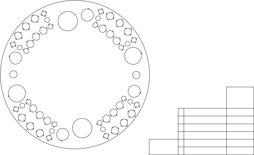
58 Station - 4 Auto-Index Turret Configuration
|
|
|
|
|
|
|
319 |
|
|
|
|
|
314 |
|
115 |
216 |
|
321 |
|
|
311 |
|
|
|
|
|
|
||
|
|
213 |
|
|
|
|
|
||
|
|
|
|
|
218 |
|
|
||
|
|
|
|
A/I |
|
323 |
|
||
|
|
|
|
|
|
|
|||
309 |
|
|
|
117 |
|
|
|||
|
|
|
|
|
|
|
|||
|
112 |
|
|
120 |
|
|
|||
|
|
110 |
|
|
|
325 |
|||
|
|
|
|
|
|
|
|
||
|
|
|
|
|
|
|
|
122 |
|
307 |
108 |
|
|
|
|
|
|
||
|
|
|
|
|
|
227 |
|||
204 |
106 |
|
|
|
|
|
|
124 |
|
|
|
|
|
|
|
|
328 |
||
305 |
|
|
|
|
|
|
|
126 |
|
|
103 |
|
|
|
|
|
|
|
|
202 |
|
|
|
|
|
|
|
229 |
|
|
|
|
|
|
|
|
|
||
|
|
|
|
|
|
|
|
|
|
|
|
|
|
|
1200mm disk |
|
|
|
|
201 A/I |
|
|
|
58 STATION |
|
|
A/I 230 |
||
|
|
|
|
4 AUTO INDEX |
|
|
|
||
258 |
|
|
|
|
|
|
|
|
231 |
|
|
|
|
|
|
|
|
|
|
|
155 |
|
|
|
|
|
|
132 |
334 |
|
|
|
|
|
|
|
|
||
357 |
|
|
|
|
|
|
|
|
|
|
|
|
|
|
|
|
135 |
233 |
|
|
153 |
|
|
|
|
|
|
||
256 |
|
|
|
|
|
|
|
|
|
|
|
|
|
|
|
|
137 |
336 |
|
|
|
151 |
|
|
|
|
|
||
|
|
|
|
|
|
|
|
||
354 |
|
|
|
|
|
139 |
|
||
|
149 |
|
|
|
|
||||
|
|
|
|
144 |
141 |
338 |
|||
|
|
|
|
146 |
|
||||
|
352 |
|
|
|
|
||||
|
|
|
|
|
|
|
|
||
|
|
|
|
|
|
242 |
|
|
|
|
|
247 |
|
|
A/I |
340 |
|
||
|
|
350 |
|
245 |
|
343 |
|
|
|
|
|
|
|
|
|
|
|||
|
|
|
|
|
|
|
|
|
|
|
|
|
348 |
|
|
|
|
|
|
VIPROS 358 KING VIPROS 368 KING
VIPROS 558 VIPROS 568
PEGA 358S
|
|
|
Number of |
|
|
|
Maximum |
Stations |
|
|
|
Size Round |
(Keyed) |
|
|
|
|
|
|
|
A |
½" (12.7mm) |
24 |
(16) |
|
B |
1¼" (31.7mm) |
24 |
(24) |
|
C |
2" (50.8mm) |
4 |
(4) |
|
D |
3½" (88.9mm) |
2 |
(2) |
|
B |
1¼" (31.7mm) |
2 |
(2) |
Auto Index |
|
|
|
|
|
E |
4½" (114.3mm) |
2 |
(2) |
Print Date 02/06/2001 Revision 4.0 |
This document available on the World Wide Web at http://www.amada.com |
Page 7 of 37 |
|
|
|

 Type II Vipros 358 King User Pre-installation Guide ©Amada America, Inc.
Fanuc 18PC Controller
Model |
Fanuc 18PC (with PHNC) |
|||
Control Function |
X, Y, T & C |
|
||
Input Method |
MDI, Paper Tape, DNC |
|||
Minimum Command Unit |
0.001" (X, Y) .010 (C) |
|
||
Minimum Travel Unit |
0.001" (X, Y) .010 (C) |
|
||
Operating Modes |
Automatic, MDI & Manual |
|||
Display Modes |
Program Contents, Position Information, Program Check, Parameters, Tool Hit |
|||
|
|
Counter, Self Diagnostics |
||
Interlock Displays |
Oil Temperature, Oil Pressure, Door Open |
|||
Hydraulic Systems Specifications |
|
|||
|
Power Hydraulic Numerical Control |
|
||
|
Ram Cycle Patterns |
|
277 Total |
|
|
|
|
Punching |
2 |
|
|
|
Nibbling |
1 |
|
|
|
Forming |
250 |
|
|
|
Marking |
10 |
|
|
|
Knockouts |
10 |
|
|
|
Slitting |
4 |
|
Minimum Programmable Increment |
|
0.001” |
|
|
Hydraulic Power Unit |
|
|
|
|
Model |
|
Yuken |
|
|
Dual Operating Pressure |
|
100 kgf cm² & 195 kgf cm² |
|
|
Oil Type |
|
Mobil DTE® Excel 46 (formerly called Mobil Hydraulic Oil NZ 46) |
|
|
Oil Capacity |
|
40 Gallons |
|
Print Date 02/06/2001 Revision 4.0 |
This document available on the World Wide Web at http://www.amada.com |
Page 8 of 37 |
|
|
|

 Type II Vipros 358 King User Pre-installation Guide ©Amada America, Inc.
Electrical Requirements
Type II Vipros 358 King |
230 / 460 / 3 / 60 ±10%, |
28 kVA |
|
63 amps @ 230 / 3 / 60 VAC** |
|
|
32 amps @ 460 / 3 / 60 VAC** |
|
SBC EX 5.5 Chiller* |
230 or 460 / 3 / 60 ±10%, 15 kVA |
|
|
38 amps @ 230 / |
3 / 60 VAC** |
|
19 amps @ 460 / |
3 / 60 VAC** |
*The SBC EX 5.5 Chiller voltage must be specified when machine is ordered.
Optional Equipment
Conveyor |
208 |
/ 230 / 460 3ph ±10%, kVA |
||
|
|
2.1 amps @ 208 |
/ 3/ 60 VAC** |
|
|
|
2.0 amps @ 230 |
/ 3 / 60 VAC** |
|
|
|
1.0 amps @ 460 |
/ 3 / 60 VAC** |
|
NJMP1225 Loader |
200 |
/ 3 / 60 ±10%, |
10 Kva |
|
|
|
29 amps @ |
200 / 3 / 60 VAC** |
|
To operate at 230 / 460 VAC a step up transformer is required with the following service is required
26 amps** @ 230 / 3 / 60 VAC**
13 amps** @ 460 / 3 / 60 VAC**
**The actual supplied electrical service must be sized to allow for starting current of approximately 150% of this value.
Print Date 02/06/2001 Revision 4.0 |
This document available on the World Wide Web at http://www.amada.com |
Page 9 of 37 |
|
|
|
Type II Vipros 358 King User Pre-installation Guide |
©Amada America, Inc. |
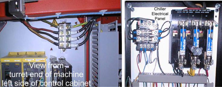
Installing the Electrical Power Supply
The Type II Vipros 358 King requires two separate electrical power sources. The first power source is supplied to the Fanuc 18PC. The other supply source goes to the SBC EX 5.5 Chiller. The Type II Vipros 358 King should be supplied from a power line separate from those for welding machines or other machines that produce electrical noise.
!The Type II Vipros 358 King electrical inlet is 64" above floor level at the rear of the Fanuc 18PC control.
!The SBC EX 5.5 Chiller electrical inlet is approximately 53" above floor level.
Type II Vipros 358 King electrical enclosure SBC EX 5.5 Chiller electrical enclosure
Print Date 02/06/2001 Revision 4.0 |
This document available on the World Wide Web at http://www.amada.com |
Page 10 of 37 |
|
|
|
Type II Vipros 358 King User Pre-installation Guide |
©Amada America, Inc. |
Pneumatic Requirements
Type II Vipros 358 King** 80 psi @ 8.8 ft³/min.
Optional Equipment
NJMP1225 Loader** |
75 psi @ 31.8 ft3/min. |
Installing the Air Supply
The Type II Vipros 358 King requires connection to a compressed air system by hose or pipe. The compressed air must be clean and dry.
Please note the following:
!The minimum pipe inside diameter is ½".
!The air pressure required is 80 psi.
!The air volume required is 8.8 ft³/min..
The air inlet is approximately 16" above the floor level at the rear of the Type II Vipros 358 King
Print Date 02/06/2001 Revision 4.0 |
This document available on the World Wide Web at http://www.amada.com |
Page 11 of 37 |
|
|
|

Type II Vipros 358 King User Pre-installation Guide |
©Amada America, Inc. |
Planning the Location of the Machine
The following diagrams provide the details for positioning the Type II Vipros 358 King.
!No obstacles are allowed in the worksheet travel area and the ceiling must be at least 40" above the top of the Type II Vipros 358 King.
!All of the recommended maintenance areas should be used, but at a minimum the doors of the Fanuc 18PC NC unit must be able to be opened. Any reduction of the listed maintenance areas may increase time and expense of installation and maintenance
!The Type II Vipros 358 King and Fanuc 18PC control must be protected from direct sunlight or other heat sources. Direct exposure to direct heating sources such as infrared heaters have been shown to affect punch and die alignment.
!The positioning of the SBC EX 5.5 Chiller is very flexible. See page 18, SBC EX 5.5 Chiller, for details.
Moving the Vipros Type II Vipros 358 King
Lifting or moving of the Type II Vipros 358 King should be done only by professional rigging companies well versed in the moving of large and heavy industrial machinery. Acceptable moving methods include, lifting by overhead crane as shown, wheeled dollies beneath the machine feet, or adequately sized
forklift forks beneath the machine frame.
The Type II Vipros 358 King has a relatively high center of gravity and narrow footprint care must be taken to prevent inadvertent tipping of the machine while in motion.
CAUTION: TOP HEAVY LOAD
35,200 lb.@ 76" |
This cover |
121" |
This cover |
|
may need to |
may need to |
||
|
|||
be removed |
|
be removed |
Print Date 02/06/2001 Revision 4.0 |
This document available on the World Wide Web at http://www.amada.com |
Page 12 of 37 |
|
|
|
 Loading...