


Vipros lll Z/K 3610 NT User Pre-installation Guide |
©Amada America, Inc. |
Vipros lll Z/K 3610 NT with AMNC-F
User Pre-installation Guide
|
|
Amada America Inc. |
|
|
|
7025 Firestone Blvd. |
|
|
|
Buena Park CA. 90621 |
|
|
|
Phone: (714) |
739 2111 |
|
|
Fax.: (714) |
739 4099 |
|
|
Email info@amada.com |
|
|
|
|
|
Print Date 08/11/2004 Revision 2.0 |
This document available on the World Wide Web at http://www.amada.com |
Page 1 of 39 |
|
Vipros lll Z/K 3610 NT User Pre-installation Guide |
©Amada America, Inc. |
Warning
Y Qualified personnel must complete all work.
Y Do not apply power to the Vipros lll Z/K 3610 NT until an Amada Engineer is present and has instructed you to do so.
Y Considerable effort has been made to ensure that this manual is free of inaccuracies and omissions. However, as we are constantly improving our product, some of the data contained herein may be out of date. Please check our Internet site, http://www.amada.com, for the latest release of this document.
Print Date 08/11/2004 Revision 2.0 |
This document available on the World Wide Web at http://www.amada.com |
Page 2 of 39 |
Vipros lll Z/K 3610 NT User Pre-installation Guide |
©Amada America, Inc. |
Contents |
|
Introduction...................................................................................................................................................................................... |
5 |
Motion Package Specifications........................................................................................................................................................ |
6 |
Punching System Specifications ..................................................................................................................................................... |
6 |
58 Station - 4 Auto-Index Turret Configuration............................................................................................................................ |
7 |
58 Station - 2 Auto-Index - Z Type Turret Configuration ................................................................................................................. |
8 |
45 Station - 4 Auto-Index - Z Type Turret Configuration ................................................................................................................. |
9 |
AMNC-F Controller ........................................................................................................................................................................ |
10 |
Hydraulic Systems Specifications.................................................................................................................................................. |
10 |
Power Hydraulic Numerical Control (P.H.N.C.) ......................................................................................................................... |
10 |
Hydraulic Power Unit................................................................................................................................................................. |
10 |
Electrical Requirements................................................................................................................................................................. |
11 |
Optional Equipment................................................................................................................................................................... |
11 |
Installing the Electrical Power Supply ....................................................................................................................................... |
12 |
Pneumatic Requirements .............................................................................................................................................................. |
13 |
Optional Equipment................................................................................................................................................................... |
13 |
Installing the Air Supply............................................................................................................................................................. |
13 |
Planning the Location of the Machine ........................................................................................................................................... |
14 |
Moving the Vipros lll Z/K 3610 NT............................................................................................................................................. |
14 |
Plan View - Vipros lll Z/K3610NT .............................................................................................................................................. |
15 |
Plan View - Vipros lll Z/K3610NT (shown with MP1530 loader)................................................................................................ |
16 |
Detailed Plan View - Vipros lll Z/K3510NT ................................................................................................................................ |
17 |
End View – Vipros lll Z/K3510NT .............................................................................................................................................. |
18 |
Elevation View – Vipros lll Z/K3510NT...................................................................................................................................... |
19 |
SBC EX 5.5 Chiller ........................................................................................................................................................................ |
20 |
SBC EX 5.5 Cautions................................................................................................................................................................ |
20 |
Chiller Connections ................................................................................................................................................................... |
21 |
Chiller Placement ...................................................................................................................................................................... |
21 |
Foundation Requirements ............................................................................................................................................................. |
22 |
Foundation Anchoring Procedure.................................................................................................................................................. |
23 |
Print Date 08/11/2004 Revision 2.0 |
This document available on the World Wide Web at http://www.amada.com |
Page 3 of 39 |
Vipros lll Z/K 3610 NT User Pre-installation Guide |
©Amada America, Inc. |
Foundation J-bolt Detail ............................................................................................................................................................ |
23 |
Foundation Plan View ............................................................................................................................................................... |
24 |
Foundation Elevation View........................................................................................................................................................ |
24 |
Machine Anchoring Requirements ................................................................................................................................................ |
25 |
Floor J-bolt Hole Detail (saw cut hole) ...................................................................................................................................... |
25 |
Floor J-bolt Hole Plan View (saw cut hole)................................................................................................................................ |
25 |
Alternative Floor J-bolt Hole Detail (Core Drill).......................................................................................................................... |
26 |
Alternative Floor J-bolt Hole Plan View (Core Drill)................................................................................................................... |
26 |
Foundation / Floor J-bolt Mounting Procedure .......................................................................................................................... |
27 |
Alternative Anchoring Method (Drilled Hole with Anchor Rod and Adhesive) ........................................................................... |
29 |
Alternative Anchoring Method Plan View (Drilled Hole with Anchor Rod and Adhesive) .......................................................... |
29 |
Drilled Hole with Anchor Rod and Adhesive Mounting Procedure ............................................................................................ |
30 |
Removing the Protective Coating .................................................................................................................................................. |
32 |
Machine Leveling........................................................................................................................................................................... |
33 |
Rocking Test ............................................................................................................................................................................. |
34 |
Floor Condition: Crowned.......................................................................................................................................................... |
35 |
Floor Condition: Sloped............................................................................................................................................................. |
36 |
Leveling Procedure ................................................................................................................................................................... |
37 |
Print Date 08/11/2004 Revision 2.0 |
This document available on the World Wide Web at http://www.amada.com |
Page 4 of 39 |
Vipros lll Z/K 3610 NT User Pre-installation Guide |
©Amada America, Inc. |
Introduction
This manual describes the tasks that the purchaser of a Vipros lll Z/K 3610 NT must complete before calling the service organization to complete the installation and operator training.
An overview of the preparations is as follows:
Y Plan the location of the Vipros lll Z/K 3610 NT in the shop, taking into account all the maintenance areas indicated on the floor plan. See page 14, Planning the Location of the Machine, for details.
Y Prepare the Vipros lll Z/K 3610 NT floor or foundation as required. See page 22, Foundation Requirements, for details.
Y For additional information on Scrap Conveyor options, see “Vipros 3610 nt Drawings Rev2.pdf” available at www.amada.com.
Y Uncrate the Vipros lll Z/K 3610 NT and on the foundation, but do not fill the anchor-bolt holes (if used) until after A.E.S.I. completes the initial installation.
Y Install the electrical supply. See page 11, Electrical Requirements, for details
Y Install the pneumatic supply. See page 13, Pneumatic Requirements, for details.
Y Remove the protective coating from the surface of the Vipros lll Z/K 3610 NT See page 32, Removing the Protective Coating, for details.
Note: It is the purchaser’s responsibility to install any safety devices to ensure the safety area.
Print Date 08/11/2004 Revision 2.0 |
This document available on the World Wide Web at http://www.amada.com |
Page 5 of 39 |

 Vipros lll Z/K 3610 NT User Pre-installation Guide ©Amada America, Inc.
Motion Package Specifications
Travel Method |
X and Y axes work piece movement |
|||
Control Method |
X, Y, T & C |
|
|
|
Drive Motors |
Fanuc AC Servo (X, Y, T, C) |
|||
Maximum Sheet Size |
60" (Y) x 196.85"" (X) with one repositioning cycle. (Additional material support |
|||
|
tables required when processing material over 100” in the X-axis) |
|||
Maximum Sheet Thickness |
0.135" |
|
|
|
Maximum Material Weight |
154 lb. |
|
|
|
Maximum Axis Travel |
98.425" (X) by 60" (Y) |
|
|
|
Max. Linear Table Speed (X / Y / Combined) |
3934 ipm / 3149 ipm / 5039 ipm |
|||
Punching Accuracy |
±0.0027" |
|
|
|
Positioning Accuracy |
±0.001" |
|
|
|
Repeatability |
±0.001" |
|
|
|
Punching System Specifications |
|
|
|
|
Press Capacity |
33 Tons |
|
|
|
Press Stroke |
1.772" |
|
|
|
Stroke Rate (X/Y) |
Pitch |
Stroke |
Stroke Rate |
|
|
0.079" |
0.236" |
600/510 |
|
|
1.000" |
0.236" |
410/320 |
|
Maximum Hole Diameter |
4.500" |
|
|
|
Tool Type |
Amada Thick Turret |
|
|
|
Turret Rotation Speed |
33 RPM |
|
|
|
Feed Clearance |
0.984" |
|
|
|
Auto Index Rotation Speed |
60 RPM |
|
|
|
Print Date 08/11/2004 Revision 2.0 |
This document available on the World Wide Web at http://www.amada.com |
Page 6 of 39 |

Vipros lll Z/K 3610 NT User Pre-installation Guide |
©Amada America, Inc. |
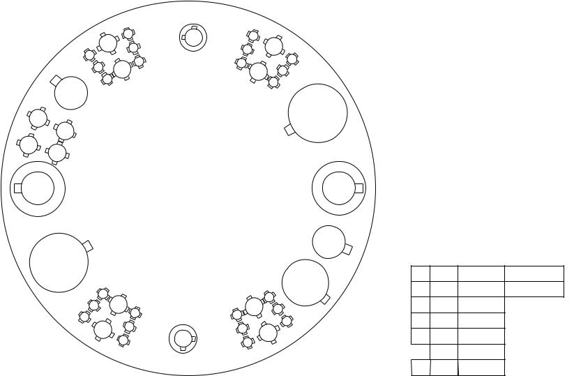
58 Station - 4 Auto-Index Turret Configuration
|
|
|
|
|
|
|
319 |
|
|
|
|
|
314 |
|
115 |
216 |
|
321 |
|
|
311 |
|
|
|
|
|
|
||
|
|
213 |
|
|
|
|
|
||
|
|
|
|
|
218 |
|
|
||
|
|
|
|
A/I |
|
323 |
|
||
|
|
|
|
|
|
|
|||
309 |
|
|
|
117 |
|
|
|||
|
|
|
|
|
|
|
|||
|
112 |
|
|
120 |
|
|
|||
|
|
110 |
|
|
|
325 |
|||
|
|
|
|
|
|
|
|
||
|
|
|
|
|
|
|
|
122 |
|
307 |
108 |
|
|
|
|
|
|
||
|
|
|
|
|
|
227 |
|||
204 |
106 |
|
|
|
|
|
|
124 |
|
|
|
|
|
|
|
|
328 |
||
305 |
|
|
|
|
|
|
|
126 |
|
|
103 |
|
|
|
|
|
|
|
|
202 |
|
|
|
|
|
|
|
229 |
|
|
|
|
|
|
|
|
|
||
|
|
|
|
|
|
|
|
|
|
|
|
|
|
|
1200mm disk |
|
|
|
|
201 A/I |
|
|
|
58 STATION |
|
|
A/I 230 |
||
|
|
|
|
4 AUTO INDEX |
|
|
|
||
258 |
|
|
|
|
|
|
|
|
231 |
|
|
|
|
|
|
|
|
|
|
|
155 |
|
|
|
|
|
|
132 |
334 |
|
|
|
|
|
|
|
|
||
357 |
|
|
|
|
|
|
|
|
|
|
|
|
|
|
|
|
135 |
233 |
|
|
153 |
|
|
|
|
|
|
||
256 |
|
|
|
|
|
|
|
|
|
|
|
|
|
|
|
|
137 |
336 |
|
|
|
151 |
|
|
|
|
|
||
|
|
|
|
|
|
|
|
||
354 |
|
|
|
|
|
139 |
|
||
|
149 |
|
|
|
|
||||
|
|
|
|
144 |
141 |
338 |
|||
|
|
|
|
146 |
|
||||
|
352 |
|
|
|
|
||||
|
|
|
|
|
|
|
|
||
|
|
|
|
|
|
242 |
|
|
|
|
|
247 |
|
|
A/I |
340 |
|
||
|
|
350 |
|
245 |
|
343 |
|
|
|
|
|
|
|
|
|
|
|||
|
|
|
|
|
|
|
|
|
|
348 |
Auto Index |
|
VIPROS 358 KING VIPROS 368 KING
VIPROS 558 VIPROS 568
PEGA 358S
|
|
Number of |
|
|
Maximum |
Stations |
|
|
Size Round |
(Keyed) |
|
|
|
|
|
A |
½" (12.7mm) |
24 |
(16) |
B |
1¼" (31.7mm) |
24 |
(24) |
C |
2" (50.8mm) |
4 |
(4) |
D |
3½" (88.9mm) |
2 |
(2) |
B |
1¼" (31.7mm) |
2 |
(2) |
E |
4½" (114.3mm) |
2 |
(2) |
Print Date 08/11/2004 Revision 2.0 |
This document available on the World Wide Web at http://www.amada.com |
Page 7 of 39 |

Vipros lll Z/K 3610 NT User Pre-installation Guide |
©Amada America, Inc. |
58 Station - 2 Auto-Index - Z Type Turret Configuration
A/I 220
219 |
|
|
318 |
217 |
116 |
|
||
|
|
|
|
333 |
336 |
237 |
340 |
|
342 |
|
|
|
|
|
|
|||
|
|
|
|
|
|
||
331 |
|
235 |
|
239 |
|
|
|
|
|
|
|
|
|
|
|
230 |
132 |
134 |
|
138 |
141 |
|
345 |
|
|
|
|
|
|||
129 |
|
|
|
|
|
244 |
|
|
|
|
|
|
|
|
|
228 |
|
|
|
|
|
143 |
246 |
349
 248
248


147 


 351
351  150
150 
This turret used on the following machine models Vipros lll 3510Z NT, Vipros lll 3610Z NT
|
152 |
253 |
354 |
|
|
||
|
|
|
|
58 STATION - Z Type |
|
255 |
|
2 AUTO INDEX |
|
|
|
114 |
|
|
|
|
A/I |
|
|
|
315 |
|
|
|
|
256 |
|
|
|
|
|
|
|
|
|
|
|
|
111 |
|
|
|
|
|
|
|
|
212 |
|
|
|
|
|
|
|
|
313 |
|
|
|
|
|
|
|
NUMBER OF |
|
|
|
|
|
264 |
MAXIMUM SIZE |
||
210 |
|
|
|
|
STATIONS |
|||
|
|
|
|
|
ROUND |
|||
107 |
|
|
|
|
165 |
|
( KEYED ) |
|
|
|
|
|
|
|
|||
208 |
|
105 |
|
168 |
266 |
|
|
|
|
|
A |
1/2" ( 12.7mm ) |
36 ( 36 ) |
||||
309 |
|
102 |
|
170 |
367 |
|||
|
|
B |
1 1/4" ( 31.7mm ) |
12 ( 12 ) |
||||
|
|
|
||||||
|
|
|
|
|||||
|
306 |
|
|
271 |
369 |
|||
|
203 |
201 |
C |
2" ( 50.8mm ) |
4 ( 4 ) |
|||
|
|
|
|
|||||
|
|
|
|
|
3 1/2" ( 88.9mm ) |
2 ( 2 ) |
||
|
|
304 |
|
372 |
|
D |
||
|
|
|
|
|
|
|||
|
|
|
|
|
|
|
||
|
|
|
|
|
|
E |
4 1/2" ( 114.3mm ) |
2 ( 2 ) |
|
|
|
|
|
AUTO INDEX |
B |
1 1/4" ( 31.7mm ) |
2 ( 2 ) |
Print Date 08/11/2004 Revision 2.0 |
This document available on the World Wide Web at http://www.amada.com |
Page 8 of 39 |
Vipros lll Z/K 3610 NT User Pre-installation Guide |
©Amada America, Inc. |
45 Station - 4 Auto-Index - Z Type Turret Configuration
|
311 |
314 |
215 |
318 |
320 |
|
213 |
|
217 |
||
309 |
|
|
|||
|
112 |
|
116 |
323 |
|
|
|
|
|||
208 |
|
110 |
|
119 |
222 |
|
107 |
121 |
|
|
|
|
206 |
|
305 |
|
224 |
|
|
|
|
104 |
|
303 |
102 |
|
|
|
201 |
45 Station - Z Type |
225 |
|
4 Auto Index |
|||
|
|
226
245
142 |
|
|
|
|
|
227 |
|
|
|
|
|
128 |
|
243 |
140 |
|
|
|
131 |
|
137 |
|
133 |
229 |
|||
344 |
|
|
|
|||
|
|
|
330 |
|||
|
341 |
238 |
|
234 |
|
|
|
236 |
332 |
||||
|
|
339 |
335 |
|
|
|
|
|
|
|
|
||
This Turret Configuration Used On Vipros lll 3510Z NT, Vipros lll 3610Z NT
Maximum |
Number |
|
Of Stations |
||
Size Round |
||
(Keyed) |
||
|
||
|
|
|
A |
½" |
12.7mm |
24 |
(24) |
|
B |
1¼" |
31.7mm |
12 |
(12) |
|
C |
|
|
|
|
|
2" |
50.8mm |
2 |
(2) |
|
|
D |
3½" |
88.9mm |
1 |
(1) |
|
E |
|
|
|
|
|
4½" |
114.3mm |
2 |
(2) |
|
Auto |
B |
1¼" |
31.7mm |
2 |
(2) |
Index |
C |
2" |
50.8mm |
2 |
(2) |
Print Date 08/11/2004 Revision 2.0 |
This document available on the World Wide Web at http://www.amada.com |
Page 9 of 39 |

 Vipros lll Z/K 3610 NT User Pre-installation Guide ©Amada America, Inc.
AMNC-F Controller
|
Model |
AMNC-F (with PHNC) |
|
|
|
Control Function |
X, Y, T & C |
|
|
|
Input Method |
MDI, DNC |
|
|
|
Minimum Command Unit |
0.001" (X, Y) 0.010 (C) |
||
|
Minimum Travel Unit |
0.001" (X, Y) 0.010 (C) |
||
|
Operating Modes |
Automatic, MDI & Manual |
||
|
Display Modes |
Program Contents, Position Information, Program Check, Parameters, Tool Hit |
||
|
|
Counter, Self Diagnostics |
||
|
Interlock Displays |
Oil Temperature, Oil Pressure, Door Open |
||
Hydraulic Systems Specifications |
|
|||
|
Power Hydraulic Numerical Control (P.H.N.C.) |
|||
|
Ram Cycle Patterns |
|
277 Total |
|
|
|
|
Punching |
2 |
|
|
|
Nibbling |
1 |
|
|
|
Forming |
250 |
|
|
|
Marking |
10 |
|
|
|
Knockouts |
10 |
|
|
|
Slitting |
4 |
|
Minimum Programmable Increment |
|
0.001” |
|
|
Hydraulic Power Unit |
|
|
|
|
Model |
|
Yuken |
|
|
Dual Operating Pressure |
|
100 kgf cm² & 195 kgf cm² |
|
|
Oil Type |
|
Mobil DTE® Excel 46 (formerly called Mobil Hydraulic Oil NZ 46) |
|
|
Oil Capacity |
|
40 Gallons |
|
Print Date 08/11/2004 Revision 2.0 |
This document available on the World Wide Web at http://www.amada.com |
Page 10 of 39 |
 Vipros lll Z/K 3610 NT User Pre-installation Guide ©Amada America, Inc.
Electrical Requirements
Vipros lll Z/K 3610 NT |
200 VAC 3 PHASE 60 HZ. ±10%, 88 Amps**, 30 kVA . |
||
|
230/460 requires step-up transformer |
||
SBC EX 5.5 Chiller* |
230 or 460 / 3 / 60 |
±10%, 15 kVA |
|
|
38 amps @ 230 |
/ 3 / 60 VAC** |
|
|
19 amps @ |
460 |
/ 3 / 60 VAC** |
*The SBC EX 5.5 Chiller voltage must be specified when machine is ordered.
Optional Equipment
Conveyor |
208 |
/ 230 / 460 3ph ±10%, kVA |
||
|
|
2.1 amps @ 208 |
/ 3/ 60 VAC** |
|
|
|
2.0 amps @ 230 |
/ 3 / 60 VAC** |
|
|
|
1.0 amps @ 460 |
/ 3 / 60 VAC** |
|
MP1530 Loader |
200 |
/ 3 / 60 ±10%, |
10 Kva |
|
|
|
29 amps @ |
200 / 3 / 60 VAC** |
|
To operate at 230 / 460 VAC a step up transformer is required with the following service is required
26 amps** @ 230 / 3 / 60 VAC**
13 amps** @ 460 / 3 / 60 VAC**
**The actual supplied electrical service must be sized to allow for starting current of approximately 150% of this value.
Print Date 08/11/2004 Revision 2.0 |
This document available on the World Wide Web at http://www.amada.com |
Page 11 of 39 |

Vipros lll Z/K 3610 NT User Pre-installation Guide |
©Amada America, Inc. |
Installing the Electrical Power Supply
The Vipros lll Z/K 3610 NT requires two separate electrical power sources. The first power source is supplied to the AMNC-F.
The other supply source goes to the SBC EX 5.5 Chiller. The Vipros lll Z/K 3610 NT should be supplied from a power line separate from those for welding machines or other machines that produce electrical noise.
The Vipros lll Z/K 3610 NT electrical inlet is 75" above floor level at the rear of the AMNC-F control.
The SBC EX 5.5 Chiller electrical inlet is approximately 53" above floor level.
Vipros lll Z/K 3610 NT electrical enclosure: |
SBC EX 5.5 Chiller electrical enclosure: |
POWER CABLE INLET |
|
Main power |
|||||
|
|
|
|
|
|
|
connection |
|
|
|
|
|
|
|
|
|
|
|
|
|
|
|
|
|
|
|
|
|
|
|
|
|
|
|
|
|
|
|
|
|
|
|
|
|
|
|
|
Print Date 08/11/2004 Revision 2.0 |
This document available on the World Wide Web at http://www.amada.com |
Page 12 of 39 |
 Loading...