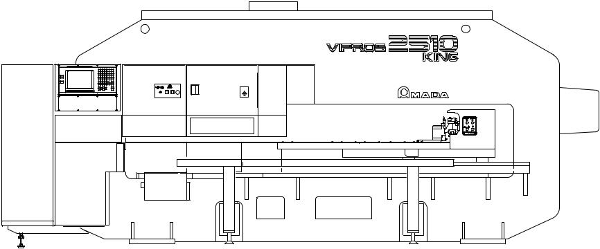
amada 2510 User Manual

Machine Programming LimitsVipros 2510 Machine Programming Limits |
©Amada America Inc. |
Vipros 2510 Machine Programming Limits
Amada America Inc. 7025 Firestone Blvd.
Buena Park, CA 90621 Phone: 714-739-2111 Fax: 714-739-4099 Email info@amada.com
Change To Subject Information All Document Preliminary
Print Date 06/28/00 Version Preliminary |
Page 1 of 15 |
|
|

Machine Programming LimitsVipros 2510 Machine Programming Limits |
©Amada America Inc. |
Table of Contents |
|
Programmable Travel Limits ................................................................................................................................................. |
3 |
Programmable Feed Rates ................................................................................................................................................... |
4 |
Punching Mode................................................................................................................................................................ |
4 |
Contouring Mode ............................................................................................................................................................. |
4 |
Punch Confirmation Area / Punching Dead Zone.................................................................................................................. |
5 |
Definitions ........................................................................................................................................................................ |
5 |
A Size (½") Station........................................................................................................................................................... |
6 |
A Size Track 200 Stations .......................................................................................................................................... |
6 |
A Size Track 300 Stations .......................................................................................................................................... |
7 |
B Size (1¼") Station......................................................................................................................................................... |
8 |
B Size Track 200 Stations (Auto Index only) .............................................................................................................. |
8 |
B Size Track 300 Stations .......................................................................................................................................... |
9 |
C Size (2") Station ......................................................................................................................................................... |
10 |
C Size Track 200 Stations ........................................................................................................................................ |
10 |
C Size Track 200 Stations Auto Index ...................................................................................................................... |
10 |
D Size (3½") Station ...................................................................................................................................................... |
12 |
D Size Track 200 Stations ........................................................................................................................................ |
12 |
Reposition Holddown Locations .......................................................................................................................................... |
13 |
Material Clamp Location...................................................................................................................................................... |
14 |
31 Station Turret ................................................................................................................................................................. |
15 |
Change To Subject Information All Document Preliminary
Print Date 06/28/00 Version Preliminary |
Page 2 of 15 |
|
|

Machine Programming LimitsVipros 2510 Machine Programming Limits |
©Amada America Inc. |
Programmable Travel Limits
|
|
|
|
|
|
|
|
Y |
Track 200 |
||
|
|
|
|
Track 300
0"
|
|
|
|
X |
|
|
|
Y-axis Movable Distance |
||
0" |
|
|
|
|
||||||
|
|
|
|
|
By Track Numbers |
|||||
|
|
Origin Statement |
|
X-axis |
Center Track |
|
Outer Track |
|||
|
|
|
|
|
|
|
|
|||
|
|
X-axis Origin |
Y-axis Origin |
Movable Distance |
200 Stations |
|
300 Stations |
|||
|
98.425" |
50.000" |
-.400" to 98.825" |
-.400" to 51.100" |
-1.900" to 49.600" |
|||||
|
|
|
|
|
|
|
|
|
|
|
Change To Subject Information All Document Preliminary
Print Date 06/28/00 Version Preliminary |
Page 3 of 15 |
|
|

 Machine Programming LimitsVipros 2510 Machine Programming Limits
Programmable Feed Rates
Punching Mode
F1 |
= |
X3937 IPM Y3149 IPM |
F2 |
= |
X2952 IPM Y2362 IPM |
F3 |
= |
X1968 IPM Y1574 IPM |
F4 |
= |
X984. IPM Y787 IPM |
Contouring Mode
G00 max. 3149 IPM
G01 max. 300 IPM
G02 max. 300 IPM optional
G03 max. 300 IPM optional
©Amada America Inc.
Change To Subject Information All Document Preliminary
Print Date 06/28/00 Version Preliminary |
Page 4 of 15 |
|
|
Machine Programming LimitsVipros 2510 Machine Programming Limits |
©Amada America Inc. |
|
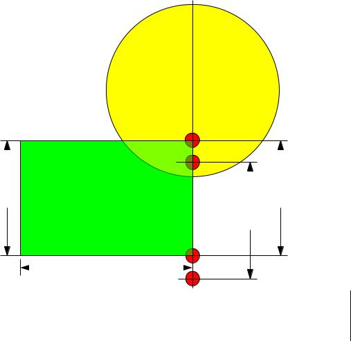
Punch Confirmation Area / Punching Dead Zone. |
|
|
Definitions |
|
|
Confirmation Zone |
= An area that when the confirmation switch is in the on position or it is the first run of the |
|
|
part program the operator must confirm the punch by pressing the confirmation |
|
|
pushbutton. |
|
Punch Dead Zone |
= Punching in this area with standard tools may damage the material, material clamp, tool, |
|
|
other machine components, and may cause operator injury. The operator must confirm |
|
|
the punch by pressing the punch and confirmation buttons. |
|
Y-Overtravel Zone |
= An area that exceeds the travel limits of the machine. |
|
Change To Subject Information All Document Preliminary
Print Date 06/28/00 Version Preliminary |
Page 5 of 15 |
|
|
 Loading...