


345
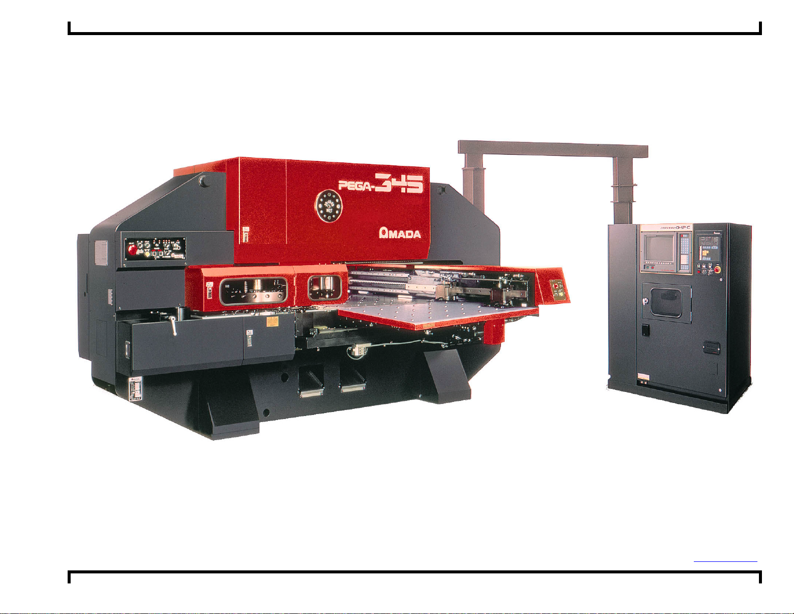
Pega 345 Queen with Fanuc 04PC User Pre-install at i on Gui de ©Amada America, Inc.
Pega 345 Queen with Fanuc 04PC
User Pre-installation Guide
Amada America I nc.
7025 Firestone Blvd.
Buena Park CA. 90621
Phone: (714) 739 2111
Fax.: (714) 739 4099
Email info@amada.com
Print Date 02/28/2001 Revision 4. 0 This document availabl e on t he World Wide Web at http://www.amada.com Page 1 of 35
Pega 345 Queen with Fanuc 04PC User Pre-install at i on Gui de ©Amada America, Inc.
Warning
! Qualified personnel must complete all work.
! Do not apply power to the Pega 345 Queen until an A.E.S.I. (Amada Engineering
and Service Incorporated) Engineer is present and has instructed you to do so.
! Considerable effort has been made to ensure that this manual is free of
inaccuracies and omissions. However, as we are constantly improving our
product, some of the data contained herein may not exactly reflect the latest
revisions to the Pega 345 Queen. If in doubt concerning a specific item, please
contact your local Amada America sales person for clarification, or check our
Internet site, http://www.amada.com for the latest release of this document.
Print Date 02/28/2001 Revision 4. 0 This document availabl e on t he World Wide Web at http://www.amada.com Page 2 of 35

Pega 345 Queen with Fanuc 04PC User Pre-install at i on Gui de ©Amada America, Inc.
Contents
Introduction ......................................................................................................................................................................................5
Specifications - Motion Package......................................................................................................................................................6
Specifications - Punching System....................................................................................................................................................6
Turret Configuration - 44 Station - 2 Auto-Index..........................................................................................................................7
Turret Configuration - 58 Station - 2 Auto-Index..........................................................................................................................8
Specifications - Fanuc 04PC Controller...........................................................................................................................................9
Supply Requirements - Electrical...................................................................................................................................................10
Optional Equipment...................................................................................................................................................................10
Installing the Electrical Power Supply........................................................................................................................................11
Supply Requirements - Pneumatic.................................................................................................................................................12
Optional Equipment...................................................................................................................................................................12
Installing the Pneumatic Supply.................................................................................................................................................12
Planning the Location of the Pega 345 Queen ..............................................................................................................................13
Moving the Pega 345 Queen.....................................................................................................................................................13
Plan View - Pega 345 Queen.....................................................................................................................................................14
Plan View - Pega 345 Queen with P345hs left side conveyor...................................................................................................15
Plan View - Pega 345 Queen with P345hs conveyor and MP1225 loader................................................................................16
End View - Pega 345 Queen.....................................................................................................................................................17
Elevation View - Pega 345 Queen.............................................................................................................................................18
Foundation Requirements..............................................................................................................................................................19
Foundation Anchoring Procedure ..................................................................................................................................................20
Foundation J-bolt Detail.............................................................................................................................................................20
Plan View - Foundation Pega 345 Queen..................................................................................................................................21
Elevation - Foundation Pega 345 Queen...................................................................................................................................21
Machine Anchoring Requirements.................................................................................................................................................22
Saw Cut J-bolt Mounting Holes..................................................................................................................................................22
Core Drill J-bolt Mounting Holes ................................................................................................................................................23
Foundation / Floor J-bolt Mounting Procedure...........................................................................................................................24
Drilled Hole with Anchor Rod and Adhesive Mounting Holes.....................................................................................................26
Drilled Hole with Anchor Rod and Adhesive Mounting Procedure.............................................................................................27
Print Date 02/28/2001 Revision 4. 0 This document availabl e on t he World Wide Web at http://www.amada.com Page 3 of 35

Pega 345 Queen with Fanuc 04PC User Pre-install at i on Gui de ©Amada America, Inc.
Removing the Protective Coating...................................................................................................................................................29
Machine Leveling...........................................................................................................................................................................30
Rocking Test..............................................................................................................................................................................30
Floor Condition: Crowned..........................................................................................................................................................31
Floor Condition: Sloped.............................................................................................................................................................32
Leveling Procedure....................................................................................................................................................................33
Print Date 02/28/2001 Revision 4. 0 This document availabl e on t he World Wide Web at http://www.amada.com Page 4 of 35

Pega 345 Queen with Fanuc 04PC User Pre-install at i on Gui de ©Amada America, Inc.
Introduction
This manual describes the tasks that the purchaser of a Pega 345 Queen must complete before calling A.E.S.I. (Amada
Engineering and Service Incorporated) to complete the installation and operator training.
An overview of the preparations is as follows:
! Plan the location of the Pega 345 Queen taking into account the Recomended Safety and Maintenance areas indicated on
the plan view. See page 13, Planning the Location of the Pega 345 Queen.
! Prepare the Pega 345 Queen floor or foundation as required. See page 19, Foundation Requirements, for details.
! Uncrate the Pega 345 Queen and place on the foundation, but do not fill the anchor-bolt holes (if used) until after A.E.S.I.
completes the initial installation.
! Install the electrical supply. See page 10, Supply Requirements - Electrical , for details.
! Install the pneumatic supply. See page 12, Supply Requirements - Pneumatic, for details.
! Remove the protective coating from the surface of the Pega 345 Queen See page 29, Removing the Protective Coating, for
details.
! If additional equipment is to be installed, repeat the previous steps for each piece of additional equipment.
Note: It is the purchaser’s responsibility to install any safety devices to ensure the recommended safety area.
Note: Considerable effort has been made to ensue that this manual is free of inaccuracies and omissions. However, as
Amada America strives to continually improve our products, some data contained herein may not exactly reflect the
latest revisions to the Pega 345 Queen. If in doubt concerning a specific item, please contact your local Amada
America sales engineer for clarification.
Print Date 02/28/2001 Revision 4. 0 This document availabl e on t he World Wide Web at http://www.amada.com Page 5 of 35

Pega 345 Queen with Fanuc 04PC User Pre-install at i on Gui de ©Amada America, Inc.
Specifications - Motion Package
Travel Method X and Y axes work piece movement
Control Method X, Y, T & C
Drive Motors Fanuc AC Servo (X, Y, T, C)
Maximum Sheet Size 40" (Y) x 100" (X) with one repositioning cycle.
Additional support tables are required for material lengths greater than 50.0"
Maximum Sheet Thickness 0.250"
Maximum Material Weight 110 lb.
Maximum Axis Travel 50.0" (X) by 40.0" (Y)
Max. Table Speed ( X / Y / Combined ) 1,968 IPM / 1,968 IPM / 2,783 IPM
Punching Accuracy ±0.004"
Positioning Accuracy ±0.001"
Repeatability ±0.001"
Specifications - Punching System
Press Capacity 33 Tons
Press Stroke 1.259"
Stroke Per Minute 350
Maximum Hit Rate 1” Centers 200
Maximum Hole Diameter 4.500"
Tool Type Amada Thick Turret
Turret Rotation Speed 30 RPM
Feed Clearance 0.787"
Print Date 02/28/2001 Revision 4. 0 This document availabl e on t he World Wide Web at http://www.amada.com Page 6 of 35
Pega 345 Queen with Fanuc 04PC User Pre-install at i on Gui de ©Amada America, Inc.
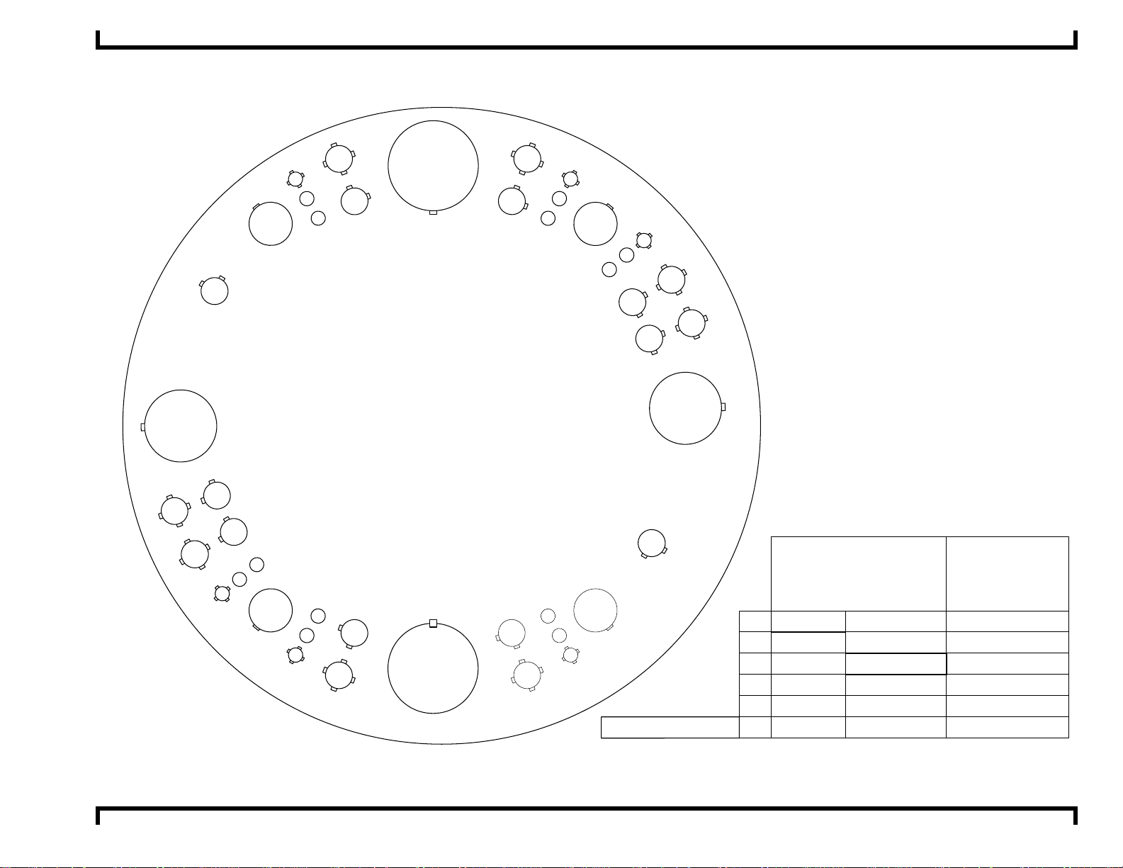
Turret Configuration - 44 Station - 2 Auto-Index
E
B
A
C
223
B
216
A/I
D
215
113
314
B
B
312
310
A
111
108
209
207
C
A
326
225
205
306
328
124
104
303
B
229
127
1000mm Disc Thick
44 Station
2 Auto Index
102
201
E
130
155
331
132
152
253
356
B
334
233
354
B
A
A
235
251
A/I
C
237
136
139
141
244
C
This turret used on the following machine models
Pega 344, 345Q, 345K, 357, 367
Coma 555, 557, 567, 588
Vipros 345, 357, 367
A
338
340
B
342
243
B
B
D
Vela II 355
MAXIMUM
SIZE ROUND
NUMBER OF
STATIONS
(KEYED)
A
B
C
D
E
B
½"
1¼"
2"
3½"
4½"
1¼"
12.7mm
31.7mm
50.8mm
88.9mm
114.3mm
31.7mm
18 (6)
16 (16)
4 (4)
2 (2)
2 (2)
2 (2)AUTO INDEX
Print Date 02/28/2001 Revision 4. 0 This document availabl e on t he World Wide Web at http://www.amada.com Page 7 of 35
Pega 345 Queen with Fanuc 04PC User Pre-install at i on Gui de ©Amada America, Inc.
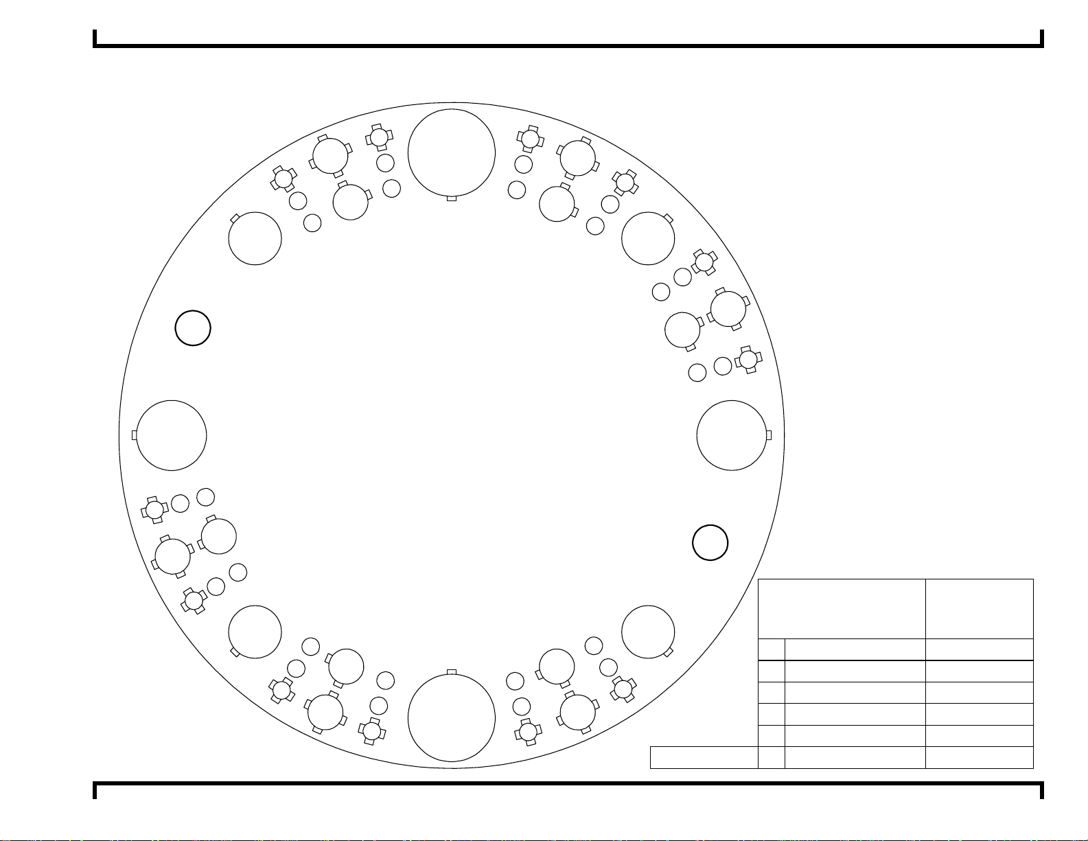
Turret Configuration - 58 Station - 2 Auto-Index
This turret used on the following machine models
PEGA 345, PEGA 345 King, PEGA 357, PEGA 367
COMA 555, COMA 557, COMA 567, COMA 588
VIPROS 345, VIPROS 357, VIPROS 367
VIPROS 357 Queen, VIPROS 367 Queen
3
54
22
A/I
333
331
230
129
228
0
132
336
235
134
237
239
138
340
141
342
143
244
345
1
246
47
9
34
2
48
3
51
1
50
2
53
1
52
1000mm disc
2
2
A/I
56
55
MAXIMUM SIZE
ROUND
1/2" ( 12.7mm )
A
1 1/4" ( 31.7mm )
B
C
D
E
B
2" ( 50.8mm )
3 1/2" ( 88.9mm )
4 1/2" ( 114.3mm )
1 1/4" ( 31.7mm )
NUMBER OF
STATIONS
( KEYED )
36 ( 12 )
12 ( 12 )
4 ( 4 )
2 ( 2 )
2 ( 2 )
2 ( 2 )
2
19
6
11
2
17
18
3
4
11
3
15
111
2
12
3
13
2
10
1
07
2
30
08
9
30
1
6
58 STATION
2 AUTO INDEX
05
102
2
03
304
2
01
2
64
65
1
1
68
1
70
2
71
3
69
3
72
2
66
3
67
AUTO INDEX
Print Date 02/28/2001 Revision 4. 0 This document availabl e on t he World Wide Web at http://www.amada.com Page 8 of 35
Pega 345 Queen with Fanuc 04PC User Pre-install at i on Gui de ©Amada America, Inc.
Specifications - Fanuc 04PC Controller
Model Fanuc 04PC
Control Function X, Y, T & C
Input Method MDI, DNC, Paper Tape
Minimum Command Unit 0.001" (X, Y) .010 (C)
Minimum Travel Unit 0.001" (X, Y) .010 (C)
Operating Modes Automatic, MDI & Manual
Display Modes Program Contents, Position Information, Program Check, Parameters, Tool Hit Counter, Self
Diagnostics
Interlock Displays Oil Temperature, Oil Pressure, Door Open
Print Date 02/28/2001 Revision 4. 0 This document availabl e on t he World Wide Web at http://www.amada.com Page 9 of 35
Pega 345 Queen with Fanuc 04PC User Pre-install at i on Gui de ©Amada America, Inc.
Supply Requirements - Electrical
Pega 345 Queen 230 / 460 / 3 / 60 ±10%, 18 kVA
46 amps @ 230 / 3 / 60 VAC*
23 amps @ 460 / 3 / 60 VAC*
Optional Equipment
P345hs Conveyor 208 / 230 / 460 3ph ±10%, .8 kVA
2.1 amps @ 208 / 3/ 60 VAC*
2.0 amps @ 230 / 3 / 60 VAC*
1.0 amps @ 460 / 3 / 60 VAC*
MP1225 Loader 200 / 3 / 60 ±10%, 10 kVA
29 amps @ 200 / 3 / 60 VAC*
To operate at 230 / 460 VAC a step up transformer with the following service is required
26 amps @ 230 / 3 / 60 VAC*
13 amps @ 460 / 3 / 60 VAC*
* The actual supplied electrical service must be sized to allow for starting current of approximately 150% of this value.
Print Date 02/28/2001 Revision 4. 0 This document availabl e on t he World Wide Web at http://www.amada.com Page 10 of 35
Pega 345 Queen with Fanuc 04PC User Pre-install at i on Gui de ©Amada America, Inc.
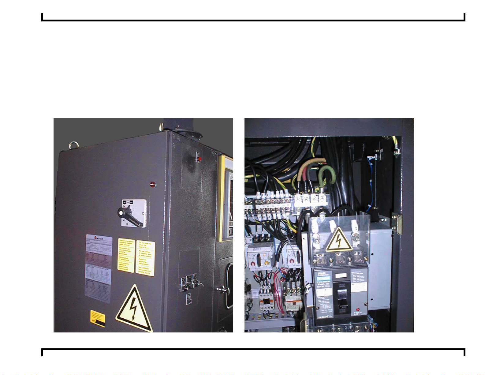
Installing the Electrical Power Supply
The Pega 345 Queen requires one electrical power source. The Pega 345 Queen should be supplied from a power line
separate from those for welding machines or other machines that produce electrical noise.
! The Pega 345 Queen electrical inlet is 64" above floor level at the left side of the Fanuc 04PC control.
! For the location of required electrical supplies for optional equipment, please see the installation guides for the specific
equipment.
Pega 345 Queen left side of electrical enclosure Pega 345 Queen power conection inside of electrical enclosure
Print Date 02/28/2001 Revision 4. 0 This document availabl e on t he World Wide Web at http://www.amada.com Page 11 of 35
 Loading...