


FBD-NT Press Brake
Installation Guide
Summary........................................................................................... |
2 |
Environmental conditions .............................................................. |
2 |
Power supply................................................................................. |
2 |
Machine installation....................................................................... |
3 |
Location ............................................................................................ |
4 |
Carrying ............................................................................................ |
5 |
Using a crane ................................................................................ |
5 |
Using rollers .................................................................................. |
6 |
Foundation ........................................................................................ |
7 |
Cleaning............................................................................................ |
7 |
Supplying hydraulic oil ...................................................................... |
8 |
Removing shipping brackets............................................................. |
9 |
Supplying electric power.................................................................. |
10 |
Changing power supply parts....................................................... |
10 |
Connecting power cable............................................................... |
13 |
Checking wiring connections........................................................ |
15 |
Re-origin .......................................................................................... |
16 |
Connecting air compressor.............................................................. |
16 |
Leveling............................................................................................ |
17 |
Paralleling upper and lower beams ................................................. |
18 |
Checking movement of each axis.................................................... |
19 |
Installing stopper fingers .................................................................. |
20 |
Making final checks.......................................................................... |
20 |
1

SUMMARY
Environmental conditions
•The higher the humidity in the place where the machine is installed, the lower the insulation performance of its electric parts becomes. This results in the premature degradation of the electric parts. Do not install the machine in such a humid place.
•Where the ambient temperature is not higher than 5°C (41°F), keep the machine and hydraulic unit energized during the day's work.
•Install the machine in a place where it is not subjected to dust, dirt, and organic or corrosive gases.
•Keep the machine at least 10 m (33 ft) away from a welder or any other equipment that may produce electric noise and magnetic fields.
Power supply
Power requirement: 200/230/400/460 V, AC, 3 phases, 50/60 Hz
Power cable: Composed of four conductors (including grounding conductor) and thick enough to carry required power
|
|
|
Full load current |
|
Power cable and ground |
|||||
Model |
Power voltage |
|
|
|
conductor (AWG) |
|
||||
|
|
|
|
|
|
|||||
|
|
200 V |
230 V |
400 V |
460 V |
200/230V |
400 V |
|
460 V |
|
3512 |
|
37 A |
32.2 A |
18.5 A |
15.9 A |
8 mm2 |
|
5.5 mm2 |
|
5.5 mm2 |
|
(8) |
|
(10) |
|
(10) |
|||||
|
|
|
|
|
|
|
|
|||
5012 |
|
44 A |
38.3 A |
22 A |
18.9 A |
14 mm2 |
|
8 mm2 |
|
8 mm2 |
|
(6) |
|
(8) |
|
(8) |
|||||
|
|
|
|
|
|
|
|
|||
5020 |
|
44 A |
38.3 A |
22 A |
18.9 A |
14 mm2 |
|
8 mm2 |
|
8 mm2 |
|
(6) |
|
(8) |
|
(8) |
|||||
|
|
|
|
|
|
|
|
|||
8020 |
|
44 A |
38.3 A |
22 A |
18.9 A |
14 mm2 |
|
8 mm2 |
|
8 mm2 |
200/230/400 |
(6) |
|
(8) |
|
(8) |
|||||
|
|
|
|
|
|
|
||||
8025 |
/460 V |
44 A |
38.3 A |
22 A |
18.9 A |
14 mm2 |
|
8 mm2 |
|
8 mm2 |
|
(6) |
|
(8) |
|
(8) |
|||||
|
|
|
|
|
|
|
|
|||
1025 |
|
59 A |
51.3 A |
29.5 A |
25.4 A |
22 mm2 |
|
14 mm2 |
|
14 mm2 |
|
(4) |
|
(6) |
|
(6) |
|||||
|
|
|
|
|
|
|
|
|||
1030 |
|
59 A |
51.3 A |
29.5 A |
25.4 A |
22 mm2 |
|
14 mm2 |
|
14 mm2 |
|
(4) |
|
(6) |
|
(6) |
|||||
|
|
|
|
|
|
|
|
|||
1253 |
|
59 A |
51.3 A |
29.5 A |
25.4 A |
22 mm2 |
|
14 mm2 |
|
14 mm2 |
|
(4) |
|
(6) |
|
(6) |
|||||
|
|
|
|
|
|
|
|
|||
NOTICE
●Supply the machine from a power source independent of a welder or any other equipment that may produce line voltage variations.
2

Machine installation
3
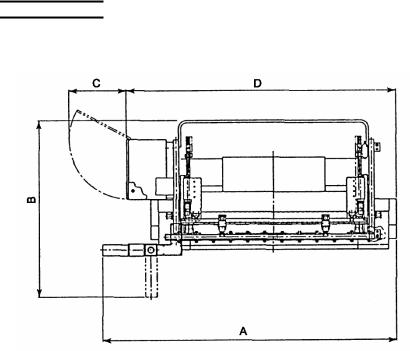
LOCATION
The place where the machine is to be installed must have an ample floor space. Refer to the machine dimensions given in the table below. Also take the following points into account:
•There must be no pillars and other obstacles in the area where the tools are mounted and removed. (At least 835 mm (32.9 in.) long tools must be able to be horizontally mounted and removed.)
•The ceiling must be at least 1000 mm (40 in.) from the top of the machine.
•There must be an additional space to place a tool storage case and an air compressor.
•There must be a work space where the worksheets can be easily moved in and out and where maintenance and part quality check can be smoothly performed. Especially, a work space of 1000 mm (40 in.) or more must be available at the rear of the machine, and an enough space must be available for the door of the electrical enclosure to be opened.
NOTICE
●Do not install the machine in a place where it is exposed to dust from such operations as sandblasting and to direct sunlight, rain or wind.
|
|
|
|
|
Unit: mm (in.) |
Model |
A |
|
B |
C |
D |
|
|
|
|
|
|
3512 |
2040 (80.38) |
1990 |
(78.41) |
680 (26.79) |
1890 (74.47) |
|
|
|
|
|
|
5012 |
2040 (80.38) |
1990 |
(78.41) |
680 (26.79) |
1890 (74.47) |
|
|
|
|
|
|
5020 |
2860 (112.69) |
1985 |
(78.21) |
680 (26.79) |
2570 (101.26) |
|
|
|
|
|
|
8020 |
2880 (113.48) |
2060 |
(81.17) |
680 (26.79) |
2610 (102.84) |
|
|
|
|
|
|
8025 |
3380 (133.18) |
2060 |
(81.17) |
680 (26.79) |
3110 (122.54) |
|
|
|
|
|
|
1025 |
3380 (133.18) |
2060 |
(81.17) |
680 (26.79) |
3110 (122.54) |
|
|
|
|
|
|
1030 |
3875 (152.68) |
2060 |
(81.17) |
680 (26.79) |
3610 (142.24) |
|
|
|
|
|
|
1253 |
3905 (153.86) |
2075 |
(81.76) |
680 (26.79) |
3630 (143.03) |
|
|
|
|
|
|
4
CARRYING
WARNING |
● Carrying the machine is very dangerous. |
|
Have a qualified contractor perform the |
||
|
||
|
carrying work. |
|
|
|
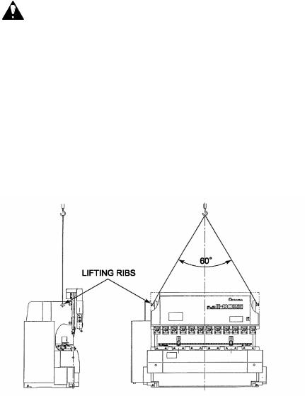
Using a crane
When lifting the machine, apply the wire rope sling to the lifting ribs at the top of the frame, slowly lift and carry the machine to the location, and slowly lower the machine at the location. The wire rope sling must be strong enough to carry the weight of the machine. (For the weight of the machine, see the serial number plate attached to the machine.)
5
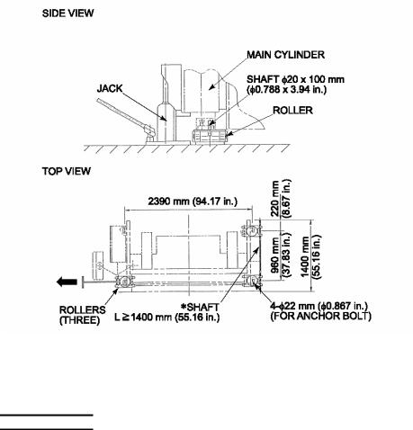
Using rollers
First jack up the front bottom of the machine under the left and right main cylinders, and place rollers under the front feet of the machine. Then slowly jack up the rear bottom of the machine, and place rollers under the rear feet of the machine. Pay attention to the balance of the machine when jacking up. Fix the rollers to the machine through the anchor bolt holes. Slowly roll the machine to its location.
The shaft marked by an asterisk ( ) is used to connect the two rollers at the right side of the machine. (Three rollers are shown in the drawing.)
NOTICE
●Be sure to first jack up the front bottom of the machine under the main cylinders.
●The machine has a center of gravity at its front. If the rear bottom of the machine is jacked up without paying attention to its balance, the machine may tip over, resulting in a very dangerous situation.
6
 Loading...