


 Loading...
CNC LASER MACHINE

(AMNC-F)
PROGRAMMING MANUAL
LASER-AMNC-F PRO-E01-200406

PREFACE This manual describes the programming procedures for the laser machine. To increase the cutting efficiency of the laser machine, read the manual carefully before creating programs.
(For operating the laser machine, refer to the separate Operator’s Manual.)
Programming Manual:
CNC Laser Machine (AMNC-F) © 2004 by AMADA CO., LTD.
No part of this publication may be photocopied or otherwise reproduced without the prior written permission of AMADA CO., LTD.
ii |
Printed in Japan |
CONTENTS
Part I |
GENERAL MACHINE COMMANDS |
|
||
|
G-Code listing ............................................................................ |
I-4 |
||
|
M-Code listing............................................................................ |
I-6 |
||
|
Machine layout........................................................................... |
I-7 |
||
|
Coordinates and dimensions ..................................................... |
I-7 |
||
|
G20 |
Select INCH coordinates.......................................... |
I-7 |
|
|
G21 |
Select METRIC coordinates..................................... |
I-8 |
|
|
G90 |
Absolute programming ............................................. |
I-8 |
|
|
G91 |
Incremental programming ........................................ |
I-8 |
|
|
G92 |
Establishing coordinate system................................ |
I-8 |
|
|
G93 |
Origin point offset ..................................................... |
I-9 |
|
|
G120 Measurement probe (for LC-θ)............................... |
I-9 |
||
|
Motion instructions.................................................................... |
I-10 |
||
|
G00 |
Rapid traverse ......................................................... |
I-10 |
|
|
G01 |
Straight line motion.................................................. |
I-11 |
|
|
G02 |
Circular arc CW ....................................................... |
I-12 |
|
|
G03 |
Circular arc CCW .................................................... |
I-14 |
|
|
G09 |
Exact stop................................................................ |
I-16 |
|
|
G61 |
Exact stop check mode ........................................... |
I-16 |
|
|
G64 |
Contour cutting mode.............................................. |
I-16 |
|
|
G160 Space arc interpolation (for LC-θ) ......................... |
I-17 |
||
|
General ..................................................................................... |
|
I-18 |
|
|
O |
Program numbers........................................................ |
I-18 |
|
|
F |
Feedrate code.............................................................. |
I-18 |
|
|
D |
Offset code .................................................................. |
I-18 |
|
|
N |
Sequence numbers ..................................................... |
I-18 |
|
|
; |
End of block .................................................................. |
I-18 |
|
|
/ |
Block skip ...................................................................... |
I-19 |
|
|
(Comments) ....................................................................... |
I-19 |
||
|
G04 |
Dwell........................................................................ |
I-19 |
|
|
G25, G27 Programmed repositioning (for LC-α) ............ |
I-20 |
||
|
G31 |
Assist gas selection................................................. |
I-20 |
|
|
G50 |
Home return ............................................................ |
I-21 |
|
|
G77 |
Measurement probe coordinate rotation (for LC-θ)..... |
I-21 |
|
|
Laser beam compensation ....................................................... |
I-22 |
||
|
G40 |
Laser beam compensation-cancel .......................... |
I-22 |
|
(Continued on next page.)
iii
G41 |
Laser beam compensation-left................................ |
I-22 |
|
G42 |
Laser beam compensation-right ............................. |
I-23 |
|
Laser control ............................................................................. |
|
I-24 |
|
G24 |
Piercing mode ......................................................... |
I-24 |
|
M100 |
Laser mode ON..................................................... |
I-24 |
|
M101 |
Laser mode OFF................................................... |
I-24 |
|
M102 |
Material designation.............................................. |
I-25 |
|
M103 |
Start cutting mode................................................. |
I-25 |
|
M104 |
Cutting mode cancel ............................................. |
I-25 |
|
M722, M723, M727 Tracking sensor calibration............. |
I-25 |
||
M758 |
Beam ON .............................................................. |
I-26 |
|
E1...E10 Cut condition select.......................................... |
I-26 |
||
E101... |
E103 |
Pierce condition select ............................... |
I-26 |
E201... |
E205 |
Edge condition select................................. |
I-26 |
Cutting parameter database.............................................. |
I-28 |
||
U, V, W macro functions ........................................................... |
I-29 |
||
Macro number usage......................................................... |
I-29 |
||
Macro memory (U, V) ........................................................ |
I-29 |
||
Macro recall (W) ................................................................ |
I-30 |
||
Nested macros .................................................................. |
I-31 |
||
Multiple part processing............................................................ |
I-33 |
||
G98 |
Multiple part setup................................................... |
I-33 |
|
To cancel G98.................................................................... |
|
I-34 |
|
G75, G76 Multiple macro recall ...................................... |
I-35 |
||
Multiple part example ........................................................ |
I-37 |
||
Multiple part processing on subcarriage side |
|
||
of FO machine ................................................................... |
I-39 |
||
General M-codes ...................................................................... |
|
I-42 |
|
M00 |
Program stop .......................................................... |
I-42 |
|
M02 |
Program end ........................................................... |
I-42 |
|
M30 Program end, return to start of program ................. |
I-42 |
||
M80, M81 Work chute open/close (for LC-α).................. |
I-42 |
||
M96 |
Call subprogram...................................................... |
I-43 |
|
M97 |
End of subprogram ................................................. |
I-43 |
|
M99 End of subprogram (for FO).................................... |
I-43 |
||
M150, M151, M152 Queue code (for FO)....................... |
I-44 |
||
M180 Cycle work chute (for LC-α).................................. |
I-44 |
||
Special ...................................................................................... |
|
|
I-45 |
G32, G33 Z-axis tracking sensor .................................... |
I-45 |
||
G65 Subprogram call (for FO) ........................................ |
I-45 |
||
G95 Call program with parameters................................. |
I-45 |
||
iv
|
G96 |
Modal program call.................................................. |
I-46 |
|
|
G97 Modal program call cancel ...................................... |
I-46 |
||
|
G107 |
Pipe Interpolation .................................................. |
I-46 |
|
|
G121, G122 HS-Edge detection ..................................... |
I-46 |
||
|
G130 |
Axes retract ........................................................... |
|
I-47 |
|
G140, G141, G149 |
OVS ................................................. |
I-47 |
|
|
G150 |
Scaling/Coordinate rotation................................... |
I-48 |
|
|
G161, G162 Space corner radius insertion (for LC-θ) .... |
I-49 |
||
|
G163 3D coordinate conversion (for LC-θ) ..................... |
I-49 |
||
|
G164 3D coordinate conversion cancel (for LC-θ).......... |
I-49 |
||
|
G165 3D conversion (for LC-θ) ....................................... |
I-49 |
||
|
G166 3D conversion cancel (for LC-θ)............................ |
I-49 |
||
|
G173 U-axis length compensation (for LC-θ) ................ |
I-49 |
||
|
M720, M721 Sensor ON/OFF (for LC-θ)......................... |
I-50 |
||
|
Loader control ........................................................................... |
|
I-51 |
|
|
G10 Pallet unload (for LC-β) ........................................... |
I-51 |
||
|
M10, M11 Workpiece clamp/release (for LC-α) .............. |
I-51 |
||
|
M20 – M29 Detectable material thickenss (for LC-α) ..... |
I-51 |
||
|
M33 Pallet load (for LC-β, FO) |
|
||
|
|
/Workpiece load (for LC-α) ..................................... |
I-51 |
|
|
M34 Pallet unload (for LC-β)........................................... |
I-51 |
||
|
M55 Cancel mirror image (for LC-β) ............................... |
I-52 |
||
|
M65 Stock function (for LC-α)......................................... |
I-52 |
||
|
M707, M772 – M774 |
Pallet change ................................ |
I-52 |
|
|
M790, M791 Pallet set (for LC-β, FO)............................. |
I-52 |
||
|
M792, M793 Pallet set pin (for LC-β, FO) ....................... |
I-52 |
||
Part II |
HOLES AND PATTERNS |
|
||
|
G-codes for holes and patterns ................................................. |
II-2 |
||
|
Standard holes.................................................................... |
|
II-2 |
|
|
Standard patterns ............................................................... |
|
II-2 |
|
|
G-codes for standard holes ....................................................... |
II-3 |
||
|
G111 |
Square/Rectangle |
|
|
|
(with Square/Radius/Chamfered corners) .......................... |
II-4 |
||
|
G112 |
Round/Obround ...................................................... |
II-6 |
|
|
G113 |
Single D/Double D .................................................. |
II-8 |
|
|
G114 |
Polygon |
|
|
|
(with Square/Radius/Chamfered corners) ......................... |
II-10 |
||
|
G115 Arc slot (Radius ends) ........................................... |
II-12 |
||
(Continued on next page.)
v
G116 Arc slot (Flat ends) ................................................ |
II-14 |
|
G-codes for standard patterns.................................................. |
II-16 |
|
General format of pattern call............................................ |
II-16 |
|
G126 |
Bolt hole circle....................................................... |
II-17 |
G128 |
Line at angle.......................................................... |
II-18 |
G129 |
Arc......................................................................... |
II-19 |
G136 |
Grid- X................................................................... |
II-20 |
G137 |
Grid- Y................................................................... |
II-21 |
vi

Part I
General Machine
Commands
|
|
|
|
..................................................................................G-Code listing |
I-4 |
||
M-Code listing .................................................................................. |
I-6 |
||
Machine layout................................................................................. |
I-7 |
||
Coordinates and dimensions ........................................................... |
I-7 |
||
G20 |
Select INCH coordinates ................................................ |
I-7 |
|
G21 |
Select METRIC coordinates........................................... |
I-8 |
|
G90 |
Absolute programming ................................................... |
I-8 |
|
G91 |
Incremental programming .............................................. |
I-8 |
|
G92 |
Establishing coordinate system...................................... |
I-8 |
|
G93 |
Origin point offset ........................................................... |
I-9 |
|
G120 Measurement probe (for LC-θ)..................................... |
I-9 |
||
Motion instructions .......................................................................... |
I-10 |
||
G00 |
Rapid traverse ............................................................... |
I-10 |
|
G01 |
Straight line motion........................................................ |
I-11 |
|
G02 |
Circular arc CW ............................................................. |
I-12 |
|
G03 |
Circular arc CCW .......................................................... |
I-14 |
|
G09 |
Exact stop...................................................................... |
I-16 |
|
G61 |
Exact stop check mode ................................................. |
I-16 |
|
G64 |
Contour cutting mode .................................................... |
I-16 |
|
G160 Space arc interpolation (for LC-θ) ............................... |
I-17 |
||
General |
........................................................................................... |
|
I-18 |
O |
Program numbers.............................................................. |
I-18 |
|
F |
Feedrate code.................................................................... |
I-18 |
|
D |
Offset code ........................................................................ |
I-18 |
|
(Continued on next page.)
I-1
N |
Sequence numbers ........................................................... |
I-18 |
||
; |
End of block ........................................................................ |
I-18 |
||
/ |
Block skip............................................................................ |
|
I-19 |
|
(Comments) ............................................................................. |
|
I-19 |
||
G04 |
Dwell.............................................................................. |
|
I-19 |
|
G25, G27 Programmed repositioning (for LC-α) .................. |
I-20 |
|||
G31 |
Assist gas selection....................................................... |
I-20 |
||
G50 |
Home return .................................................................. |
I-21 |
||
G77 |
Measurement probe coordinate rotation (for LC-θ)........... |
I-21 |
||
Laser beam compensation ............................................................. |
I-22 |
|||
G40 |
Laser beam compensation-cancel ................................ |
I-22 |
||
G41 |
Laser beam compensation-left...................................... |
I-22 |
||
G42 |
Laser beam compensation-right.................................... |
I-23 |
||
Laser control ................................................................................... |
|
I-24 |
||
G24 |
Piercing mode ............................................................... |
I-24 |
||
M100 |
Laser mode ON........................................................... |
I-24 |
||
M101 |
Laser mode OFF......................................................... |
I-24 |
||
M102 |
Material designation.................................................... |
I-25 |
||
M103 |
Start cutting mode....................................................... |
I-25 |
||
M104 |
Cutting mode cancel ................................................... |
I-25 |
||
M722, M723, M727 Tracking sensor calibration ................... |
I-25 |
|||
M758 |
Beam ON .................................................................... |
I-26 |
||
E1 |
...E10 Cut condition select................................................ |
I-26 |
||
E101... |
E103 |
Pierce condition select ..................................... |
I-26 |
|
E201... |
E205 |
Edge condition select....................................... |
I-26 |
|
Cutting parameter database .................................................... |
I-28 |
|||
U, V, W macro functions ................................................................. |
I-29 |
|||
Macro number usage............................................................... |
I-29 |
|||
Macro memory (U, V) .............................................................. |
I-29 |
|||
Macro recall (W) ...................................................................... |
I-30 |
|||
Nested macros......................................................................... |
I-31 |
|||
Multiple part processing.................................................................. |
I-33 |
|||
G98 |
Multiple part setup......................................................... |
I-33 |
||
To cancel G98.......................................................................... |
|
I-34 |
||
G75, G76 Multiple macro recall ............................................ |
I-35 |
|||
Multiple part example .............................................................. |
I-37 |
|||
Multiple part processing on subcarriage side |
|
|||
of FO machine ......................................................................... |
I-39 |
|||
General M-codes ............................................................................ |
|
I-42 |
||
M00 |
Program stop ................................................................ |
I-42 |
||
M02 |
Program end ................................................................. |
I-42 |
||
I-2
M30 |
Program end, return to start of program ....................... |
I-42 |
|
M80, M81 Work chute open/close (for LC-α)........................ |
I-42 |
||
M96 |
Call subprogram............................................................ |
I-43 |
|
M97 |
End of subprogram........................................................ |
I-43 |
|
M99 |
End of subprogram (for FO).......................................... |
I-43 |
|
M150, M151, M152 |
Queue code (for FO)............................. |
I-44 |
|
M180 Cycle work chute (for LC-α) ........................................ |
I-44 |
||
Special ............................................................................................ |
|
|
I-45 |
G32, G33 Z-axis tracking sensor .......................................... |
I-45 |
||
G65 Subprogram call (for FO)............................................... |
I-45 |
||
G95 Call program with parameters ....................................... |
I-45 |
||
G96 |
Modal program call........................................................ |
I-46 |
|
G97 Modal program call cancel ............................................ |
I-46 |
||
G107 Pipe Interpolation ........................................................ |
I-46 |
||
G121, G122 HS-Edge detection ........................................... |
I-46 |
||
G130 Axes retract ................................................................. |
|
I-47 |
|
G140, G141, G149 |
OVS ....................................................... |
I-47 |
|
G150 Scaling/Coordinate rotation......................................... |
I-48 |
||
G161, G162 Space corner radius insertion (for LC-θ) .......... |
I-49 |
||
G163 3D coordinate conversion (for LC-θ) ........................... |
I-49 |
||
G164 3D coordinate conversion cancel (for LC-θ)................ |
I-49 |
||
G165 3D conversion (for LC-θ) ............................................. |
I-49 |
||
G166 3D conversion cancel (for LC-θ).................................. |
I-49 |
||
G173 U-axis length compensation (for LC-θ) ....................... |
I-49 |
||
M720, M721 Sensor ON/OFF (for LC-θ)............................... |
I-50 |
||
Loader control ................................................................................. |
|
I-51 |
|
G10 Pallet unload (for LC-β) ................................................. |
I-51 |
||
M10, M11 Workpiece clamp/release (for LC-α) .................... |
I-51 |
||
M20 – M29 Detectable material thickenss (for LC-α) ........... |
I-51 |
||
M33 |
Pallet load (for LC-β, FO)/Workpiece load (for LC-α) ... |
I-51 |
|
M34 |
Pallet unload (for LC-β) ................................................. |
I-51 |
|
M55 |
Cancel mirror image (for LC-β) ..................................... |
I-52 |
|
M65 |
Stock function (for LC-α)............................................... |
I-52 |
|
M707, M772 – M774 |
Pallet change ...................................... |
I-52 |
|
M790, M791 Pallet set (for LC-β, FO)................................... |
I-52 |
||
M792, M793 Pallet set pin (for LC-β, FO) ............................. |
I-52 |
||
I-3
G-CODE LISTING
The machine is controlled by various G-codes and M-codes. A listing of G-codes follows. For information about M-codes, see page I-6.
CODE PURPOSE GROUP G00 Rapid traverse Motion G01 Straight line motion Motion G02 Circular arc CW Motion G03 Circular arc CCW Motion G04 Dwell General G09 Exact stop Motion G10 Pallet unload Loader
G20, G21 Select Inch/Metric coordinates Coordinates, dimensions G24 Piercing Laser
G25, G27 (for LC-α) Programmed repositioning General G31 Assist gas select General G32 Z-axis tracking sensor ON Special G33 Z-axis tracking sensor cancel Special
G40 Laser beam path compensation cancel Laser beam compensation
G41 Laser beam path compensation
to LEFT of path Laser beam compensation
G42 Laser beam path compensation
to RIGHT of path Laser beam compensation
G50 Home return General
G53 Setting in machine coordinate system Coordinates, dimensions G61 Exact stop check mode Motion
G64 Contour cutting mode Motion
G65 (for FO) Subprogram call Special G75, G76 Multiple macro recall Multiple G77 (for LC-θ) Measurement probe coordinate rotation General
G90 Absolute programming Coordinates, dimensions
G91 Incremental programming Coordinates, dimensions
G92 Establishing coordinate system Coordinates, dimensions
G93 Origin point offset Coordinates, dimensions
G95 Call Program with parameters Special
G96 Modal program call Special
G97 Modal program call cancel Special
G98 Multiple part setup Multiple G107 Pipe interpolation (for rotary table option) Special G111 Square/Rectangle Hole G112 Round/Obround Hole
I-4
G113 Single D/Double D Hole
G114 Polygon Hole
G115 Arc slot (radius ends) Hole
G116 Arc slot (flat ends) Hole
G120 (for LC-θ) Measurement probe Coordinates, dimensions G121, G122 HS-edge detection Special
G126 Bold hole circle (BHC) Pattern
G128 Line at angle (LAA) Pattern
G129 Arc (ARC) Pattern
G130 Axes retract Special G136 Grid-X (GRD-X) Pattern G137 Grid-Y (GRD-Y) Pattern G140 OVS hole detection Special G141 OVS expand function Special G149 OVS cancel Special G150 Scaling/Rotation Special G160 (for LC-θ) Space arc interpolation Motion G161 Space corner radius insertion Special G162 Space corner radius cancel Special G163 3D coordinate conversion Special G164 3D coordinate conversion cancel Special G165 3D conversion Special G166 3D conversion cancel Special G173 U-axis length compensation Special
I-5
M-CODE LISTING
M-CODE PURPOSE GROUP
M00 Program stop General M-code
M02 Program end General M-code M10, M11 (for LC-α) Workpiece clamp/release Special
M20 – M29 (for LC-α) Detectable material thickness Special
M30 Program end, return to start of program General M-code M33 (for LC-β/LC-α) Pallet load/ Workpiece load Loader
M34 (for LC-β) Pallet unload Loader M55 (for LC-β) Cancel mirror image Loader M65 (for LC-α) Stock function Loader
M80, M81 (for LC-α) Work chute open/close General M-code M96 Call subprogram General M-code M97 End of subprogram General M-code M99 (for FO) End of subprogram General M-code M100 Laser mode ON Laser
M101 Laser mode OFF Laser
M102 Material designation Laser
M103 Pierce material, start cutting mode Laser
M104 Cancel cutting mode Laser
M150, M151, M152 (for FO) Queue code General M-code M180 (for LC-α) Cycle work chute General M-code M707, M772 – M774 Pallet change Loader
M720, M721 Sensor ON/OFF Laser M722, M723, M727 Tracking sensor calibration Laser M758 Beam ON Laser M790, M791 (for LC-β) Pallet set Loader M792, M793 (for LC-β) Pallet set pin Loader
I-6

MACHINE LAYOUT
The LC-α machine and the LC-β machine are ahybrid system, with moving the material in the X-axis and moving the laser head in the Y- axis. The LC-α machine moves the material across a ball-transfer table, while the LC-β machine moves the pallet and material in the X- axis. The LC-θ or FO machine moves the laser head in the X-axis and Y-axis.
With the axes at the reference positions, the laser head is at the X+ and Y+ corner of the working area for the LC-α, -β, and -θ machines and is at the X+ and Y– corner of the working area for the FO machine.
COORDINATES AND DIMENSIONS
The NC used on these machines accepts information within certain ranges of values. The following table lists allowable values for various uses.
Numeric formats/allowable range of values |
|
|
Items |
Metric |
Inch |
X, Y, Z |
+/– 99999.9999 |
+/– 9999.9999 |
G |
1 to 9999 |
1 to 9999 |
N |
0 to 99999 |
1 to 99999 |
O |
0 to 9999 |
0 to 9999 |
R, I, J |
+/– 99999.9999 |
+/– 9999.9999 |
M |
1 to 999 |
0 to 999 |
X (as parameter) |
.001 to 9999.999 |
.001 to 9999.999 |
P |
1 to 9999 |
1 to 9999 |
G20 Select INCH coordinates
May be used in MDI, or at the beginning of a program on a line by itself. After changing coordinate system, G92 must be re-set. This may be done by re-referencing the machine (using RETRACT mode) or by using the G92 or G130 instruction.
NOTE
OIn a program, must be followed by either a G92 statement for INCH coordinates, or a G130 instruction.
I-7

G21 Select METRIC coordinates
May be used in MDI, or at the beginning of a program on a line by itself. After changing coordinate system, G92 must be re-set. This may be done by re-referencing the machine (using RETRACT mode) or by using the G92 or G130 instruction.
NOTE
OIn a program, must be followed by either a G92 statement for METRIC coordinates, or a G130 instruction.
G90 Absolute programming
When G90 is commanded, all coordinates in the program refer to current program origin or to the absolute origin point.
G90 is MODAL and remains effective until G91 is commanded.
G91 Incremental programming
When G91 is commanded, all coordinates in the program are incremental distances from the previous coordinate.
G91 is MODAL and remains effective until G90 is commanded.
G92 Establishing coordinate system
The G92 command is optional, unless the system has been switched between INCH and METRIC. Once the machine has been powered up and referenced, the standard coordinate system is ready to use.
The G92 instruction may be used to establish an absolute origin point for programming.
The usual (default) absolute origin point for the X and Y axes corresponds to the corner of the sheet of material closest to the junction of the work clamps and the X-gauge block.
NOTE
OThe G92 command must be immediately followed by the appropriate X, Y, and Z values, all on the same block of information.
When the machine has been referenced and is at “home” reference position, the NC’s position display (FUNC+POS keys) displays values which may be used in the G92 statement for the active units system (Inch/MM).
The following charts list dimensions for some common machines. If your machine does not appear here or the numbers do not seem to “match up”, confirm with AMADA the correct values for your machine and write them in below.
I-8

Machine Type |
X axis mm {in} |
Y axis mm {in} |
Z axis mm {in} |
|||
|
|
|
|
|
|
|
LC-1212 α |
1270 |
{50.000} |
1270 |
{50.000} |
300 |
{11.8110} |
|
|
|
|
|
|
|
LC-2415 α |
2520 |
{99.2126} |
1550 |
{61.0236} |
300 |
{11.8110} |
|
|
|
|
|
|
|
LC-2412 β |
2520 |
{99.2126} |
1270 |
{50.000} |
300 |
{11.8110} |
|
|
|
|
|
|
|
LC-3015 β |
3070 |
{120.8661} |
1550 |
{61.0236} |
300 |
{11.8110} |
|
|
|
|
|
|
|
LC-3015 θ |
3050 |
{120.0787} |
1530 |
{60.2362} |
700 |
{27.5590} |
|
|
|
|
|
|
|
FO2412 |
2520 |
{99.2126} |
1270 |
{50.000} |
200 |
{7.8740} |
|
|
|
|
|
|
|
FO3015 |
3070 |
{120.8661} |
1550 |
{61.0236} |
200 |
{7.8740} |
|
|
|
|
|
|
|
G93 Origin point offset
The G93 command establishes a reference origin point, relative to the absolute origin point, anywhere within the limits set by G92. This is done for ease of programming.
G93 X__ Y__ Z__; |
|
X…X-offset |
|
Y…Y-offset |
|
Z…Z-offset |
(normally zero) |
Example
G93 X0.2 Y12.0 Z0;
Shifts the part-program reference point 0.2 inches in the plus-X direction and 12.0 inches in the plus-Y direction from the absolute origin point or current reference established by a G98 multiple part instruction (see page I-33).
To cancel the origin point offset: G93 X0 Y0 Z0;
NOTE
OThe G93 command must be immediately followed by the appropriate X, Y, and Z values, all on the same block of information.
OWhen programming multiple parts using G98, the G93 refers to each part origin as set by G98.
OIf G91 (incremental coordinates) is effective when G93 is commanded, it becomes an incremental offset from the previous G93. Otherwise it replaces the previous G93.
OWhen using the cutting database, the system automatically corrects for material thickness. Unless cutting formed materials or not using the cutting database, use Z0.
G120 Measurement probe (for LC-θ)
Compensates the machine coordinate system and program origin point by using the optional measurement probe. For details, refer to the Operator’s Manual.
I-9

MOTION INSTRUCTIONS
Motion instructions belong to two groups: rapid traverse, and contouring rapid traverse (G00) is strictly for positioning the material to a particular location. Contouring instructions (G01, G02, and G03) are used to move the material through a particular path under the laser head at a particular speed (feedrate).
The system defaults to absolute coordinates programming.
G00 Rapid traverse
This command is for positioning. It moves the table and laser head to the designated X, Y axis location at the current traverse speed. (default is maximum speed)
G00 X__Y__;
The Z-axis may also be positioned, but not on the same block as with X,
Y axes.
Only axes included in the command are actually moved.
NOTE
OThe laser beam is OFF when G00 is active.
OEach axis moves independently, so the material path is usually not a straight line.
OG00 forces an in-position check at the commanded end point. This may be used to force a sharp corner during processing. (Use G00 on separate line.)
OMaximum rapid traverse speed is 40 m/min (1575 ipm). The RATE buttons on the CNC control panel can reduce travel speed to 50% or 25% of this.
OG00 is MODAL: Once commanded, it stays in effect until a G01, G02, or G03 is commanded.
OAbsolute/incremental programming is available by G90/G91.
I-10

G01 Straight line motion
Moves the material from current position to commanded location via a straight line. Feedrate, assist gas selection, laser power, pulse rate, etc. are determined by the active material and table selection (M102, En) and by active operator overrides.
G01 X__ Y__;
X…X-coordinate (mm or in.)
Y…Y-axis coordinate (mm or in.)
NOTE
OG01 is MODAL: once commanded, it remains effective until a G00, G02, or G03 is commanded.
OThe machine is capable of moving all three axes at the same time, in this mode. Absolute/Incremental programming is available by G90/G91.
OA feedrate must be specified for G01, G02, G03. This is normally done by M102 and Enn, but may also be done using an Fnnnn feedrate command.
ODuring machine operation, feedrate may be overridden from 0% to 255% in 1% steps from the operator panel.
OThe feedrate of the optional subcarriage of the FO machine is set by an NC parameter.
Example |
|
G90 G00 |
X11.0 Y20.0; |
G91 G01 |
X7.0 Y4.0; |
I-11

G02 Circular arc CW
Moves the material from current position to commanded location via a clockwise arc at a commanded radius and feedrate.
G02 X__ Y__ R__ (or I__ J__);
X… X-coordinate (mm or in.) Y… Y-axis coordinate (mm or in.)
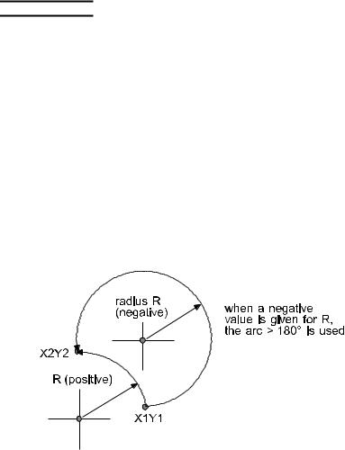
R… Radius of arc (negative value creates an arc > 180°) (can use either R or I, J in instruction)
I… Distance in the X-direction from the staring point to the arc center.
J… Distance in the Y-direction from the staring point to the arc center.
Example of R format
G90 G02 X.5 Y25.0 R2.5; Example of I, J format
G90 G02 X.5 Y25.0 I.5 J2.449;
NOTE
OG02 is MODAL: once commanded, it remains effective until a G00, G01, or G03 is commanded.
OThe parameter “R” has priority over “I” and/or “J”, when used on the same line.
OThe radius R (or that computed from I, J) must be non-zero.
OAbsolute/incremental programming available by G90/G91 only affects the end point. The I, J values are always incremental from arc starting point.
OIf the angle of the arc is greater than 180 degrees, the R value must be negative.
OThe machine is capable of moving only two axes at the same time, in this mode.
OTo cut a full circle, I and J must be used, rather than R.
OA feedrate must be specified for G01, G02, G03. This is normally done by M102 and En, but may also be done using an Fnnnn feedrate command.
ODuring machine operation, feedrate may be overridden from 0% to 255% in 1% steps from the operator panel.
I-12

I-13
G03 Circular arc CCW
Moves the material from current position to commanded location via a counter-clockwise arc.
This command is used to cut material in a counter-clockwise arc at a commanded feedrate and radius. The X and Y values specified determine the endpoint of the cut. The R value specified determines the radius of the cut.
G03 X__ Y__ R__ (or I__ J__);
X… X-coordinate (mm or in.) Y… Y-axis coordinate (mm or in.)
R… Radius of arc (negative value creates an arc > 180°) (can use either R or I, J in instruction)
I… Distance in the X-direction from the starting point to the arc center.
J… Distance in the Y-direction from the starting point to the arc center.
NOTE
OG03 is MODAL: once commanded, it remains effective until a G00, G01, or G02 is commanded.
OThe parameter “R” has priority over “I” and/or “J”, when used on the same line.
OThe radius R (or that computed from I, J) must be non-zero.
OAbsolute/incremental programming available by G90/G91 only affects the end point. The I, j values are always incremental from arc starting point.
OIf the angle of the arc is greater than 180 degrees, the R value must be negative.
OThe machine is capable of moving only two axes at the same time, in this mode.
OTo cut a full circle, I and J must be used, rather than R.
OA feedrate must be specified for G01, G02, G03. This is normally done by M102 and En, but may also be done using an Fnnnn feedrate command.
ODuring machine operation, feedrate may be overridden from 0% to 255% in 1% steps from the operator panel.
I-14
I-15

G09 Exact stop
A command effective for a specified block only. Axis travel is decelerated at the ending point of the block and checked for in-position. The next block is then executed.
G09 (G01 X__ Y__);
The command in parentheses may be G02 or G03.
NOTE
OThe in-position check refers to the check made to see if the axis travel has reached the specified position (within the range set by a parameter).
G61 Exact stop check mode
This command requires the machine to stop and wait for verification of each programmed position before moving toward the next programmed position.
NOTE
OG61 must be canceled before cutting any blended radii or using any of the standard hole commands (G111 to 115) either singly or in patterns.
OOnce G61 is commanded, it will stay in effect until a G64 is commanded.
G64 Contour cutting mode
This is the default cutting mode for the machine. No position verification is required prior to movement towards the next programmed position. This mode is in effect until changed by a G61 command.
I-16
G160 Space arc interpolation (for LC-θ)
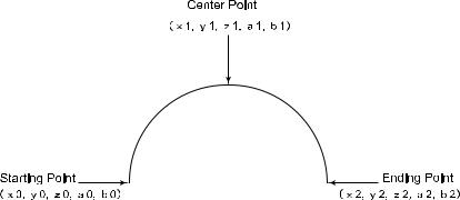
G160 Xx1 Yy1 Zz1 Va1 Ub1; Xx2 Yy2 Zz2 Va2 Ub2;
The first block indicates the center point of the arc, and the second block indicates the ending point of the arc.
G160 is MODAL and remains effective until G00, G01, G02 or G03 is commanded.
When the center point and ending point are commanded, the arc to the ending point is obtained.
When the commands for the V- and U-axes are omitted, the nozzle moves in that attitude. When the ending point is not commanded and another code (e.g., G01) is commanded, the conditions for the arc are not met. In this case, the nozzle moves with the path from the starting point to the center point straightly interpolated.
When the center point is omitted, the attitude of the nozzle is automatically controlled according to the radius of the arc from the starting point to the ending point. When another space arc interpolation is commanded, the ending point becomes the starting point of the next arc.
I-17

GENERAL
O Program numbers
Each program must be assigned a program number. This number is used to separate the 200 different programs that can be stored in memory at one time. The program number must begin with the letter “O”.
NOTE
OAny number from 0 to 8999 can be used.
OProgram 0 (zero) should be left vacant, as it can easily be overwritten during certain extended edit procedures.
OPrograms numbered 8000 to 8999 can be protected by setting a parameter.
F Feedrate code
Cutting feedrates are normally specified by using M102 to select material type and thickness, and using E1-E9 to fine-tune or select for type of contour or detail. The F-code may be used to override a standard feedrate, or for material for which an entry does not exist in the database.
NOTE
OIn Inch mode, the feedrate is in inches per minute.
OIn Metric mode, the feedrate is in millimeters per minute.
OAn F code is required only when the M102 functions are not used.
D Offset code
These codes are not used on the LC-α, β machine. Instead, laser beam offset amounts are kept in the cutting parameter database. See the section on laser beam compensation, beginning page I-22, and the section on standard holes, in Part II.
N Sequence numbers
Instruction blocks in a program may be marked or labeled using sequence numbers. When used, a sequence number must be the first address in the program block. The valid numeric range is from 1 to 99999. They do not need to be in numeric sequence.
;End of block
This symbol is used to separate one block of information from another.
I-18

/Block skip
If the block skip button is illuminated, any block of information with this symbol at its beginning will be ignored.
(Comments)
Comments may be placed in a program by enclosing them in parentheses.
If a comment is placed on the first line after the program number, it will be displayed in the program directory listing of the CNC (machine control). Comments should not be mixed into the middle of program lines. Place each comment at the end of a program line or on a separate line.
O1234 (SAMPLE COMMENT);
(THIS COMMENT IS ON A LINE BY ITSELF);
If programming off-line, make sure to use all capitals for comments and instructions.
G04 Dwell
The dwell function stops the machine for a specified period of time, in seconds.
G04 Xnnnn;
Where .001<=nnnn<=9999.999
NOTE
OCAUTION: Use of G04 between contouring motion instructions (G01, G02, G03) cancels laser beam compensation.
OWhen the time period is over, machine operation continues. Use extreme caution when using the dwell function.
OThe minimum dwell value is 0.001 second. This is equivalent to G04 with no “X” value.
I-19
Loading...