


Vipros 358 King User Pre-installation Guide |
Amada America Inc. |
Vipros 358 King User Pre-installation Guide
Print Date 11/05/97 |
Page 1 of 41 |
This document available on the World Wide Web at http://amada.com/support/pdf/v358kuig.pdf |
|

Vipros 358 King User Pre-installation Guide |
Amada America Inc. |
Warning
Qualified personnel must complete all work.
Do not apply power to the Vipros 358 King until an A.E.S.I. (Amada Engineering and Service Incorporated) Engineer is present and has instructed you to do so.
Print Date 11/05/97 |
Page 2 of 41 |
This document available on the World Wide Web at http://amada.com/support/pdf/v358kuig.pdf |
|

Vipros 358 King User Pre-installation Guide |
Amada America Inc. |
Contents |
|
Contents.................................................................................................................................................... |
3 |
Introduction ............................................................................................................................................... |
5 |
Motion Package Specifications................................................................................................................. |
6 |
Punching System Specifications............................................................................................................... |
7 |
58 Station - 4 Auto-Index Turret Configuration ................................................................................... |
8 |
Fanuc O4PC CNC Controller.................................................................................................................... |
9 |
Supply Requirements.............................................................................................................................. |
10 |
Installing the Electrical Power Supply ............................................................................................... |
11 |
Installing the Air Supply..................................................................................................................... |
12 |
Planning the Location of the Vipros 358 King......................................................................................... |
13 |
Lifting the Machine ............................................................................................................................ |
14 |
Machine Dimensions - Plan View...................................................................................................... |
15 |
Machine Dimensions - Elevation View.............................................................................................. |
16 |
Machine Dimensions - End View ...................................................................................................... |
17 |
Maintenance Areas ........................................................................................................................... |
18 |
The Chiller............................................................................................................................................... |
19 |
Chiller Placement .............................................................................................................................. |
20 |
Connections....................................................................................................................................... |
21 |
Foundation Requirements....................................................................................................................... |
22 |
Machine Anchoring Requirements.......................................................................................................... |
23 |
Print Date 11/05/97 |
Page 3 of 41 |
This document available on the World Wide Web at http://amada.com/support/pdf/v358kuig.pdf |
|

Vipros 358 King User Pre-installation Guide |
Amada America Inc. |
Floor J-bolt Mounting Hole Detail (saw cut hole) .............................................................................. |
23 |
Floor J-bolt Mounting Hole Plan View (saw cut hole) ....................................................................... |
24 |
Alternative Floor J-bolt Mounting Hole Detail (Core Drill)................................................................. |
25 |
Alternative J-bolt Mounting Method Plan View (Core Drill)............................................................... |
26 |
Floor J-bolt Mounting Procedure....................................................................................................... |
27 |
Foundation Mounting Procedure ............................................................................................................ |
29 |
Foundation J-bolt Detail .................................................................................................................... |
29 |
Foundation Plan View ....................................................................................................................... |
30 |
Foundation Elevation View................................................................................................................ |
31 |
Removing the Protective Coating ........................................................................................................... |
32 |
Machine Leveling .................................................................................................................................... |
33 |
Rocking Test...................................................................................................................................... |
34 |
Floor Condition: Crowning................................................................................................................. |
35 |
Floor Condition: Slope....................................................................................................................... |
36 |
Leveling Procedure ........................................................................................................................... |
37 |
Print Date 11/05/97 |
Page 4 of 41 |
This document available on the World Wide Web at http://amada.com/support/pdf/v358kuig.pdf |
|

Vipros 358 King User Pre-installation Guide |
Amada America Inc. |
 Introduction
This manual describes the tasks that the purchaser of a Vipros 358 King must complete before calling the service organization to complete the installation and operator training.
An overview of the preparations is as follows:
Plan the location of the Vipros 358 King in the shop, taking into account all the maintenance areas indicated on the floor plan.
Prepare the Vipros 358 King floor area as required.
Uncrate the Vipros 358 King and Fanuc O4PC control and place them on the floor.
Install the air supply.
Install the electrical supply.
Remove the protective coating from the surface of the Vipros 358 King.
Anchor the Machine to the floor or foundation using the apropriate method described in this document
Note: It is the purchaser’s responsibility to install any safety devices to ensure the safety area.
Print Date 11/05/97 |
Page 5 of 41 |
This document available on the World Wide Web at http://amada.com/support/pdf/v358kuig.pdf |
|

Vipros 358 King User Pre-installation Guide |
Amada America Inc. |
|||||
|
|
Motion Package Specifications |
|
|
||
|
|
|
|
|||
|
|
|
|
|
|
|
|
|
|
|
|
|
|
|
|
|
Travel Method |
|
X and Y axes work piece movement |
|
|
|
|
|
|
|
|
|
|
|
Control Method |
|
X, Y, T & C |
|
|
|
|
|
|
|
|
|
|
|
Drive Motors |
|
Fanuc AC Servo (X, Y, T, C) |
|
|
|
|
|
|
|
|
|
|
|
Maximum Sheet Size |
|
50.000" (Y) x 157.480" (X) with one |
|
|
|
|
|
|
repositioning cycle |
|
|
|
|
|
|
|
|
|
|
|
Maximum Sheet Thickness |
|
0.125" |
|
|
|
|
|
|
|
|
|
|
|
Maximum Material Weight |
|
110 lb. |
|
|
|
|
|
|
|
|
|
|
|
Maximum Axis Travel |
|
78.740"(X) x 50.000"(Y) |
|
|
|
|
|
|
|
|
|
|
|
Max. Linear Table Speed |
|
3150 IPM |
|
|
|
|
|
|
|
|
|
|
|
Punching Accuracy |
|
±0.004" |
|
|
|
|
|
|
|
|
|
|
|
Positioning Accuracy |
|
±0.001" |
|
|
|
|
|
|
|
|
|
|
|
Repeatability |
|
±0.001" |
|
|
|
|
|
|
|
|
Print Date 11/05/97 |
Page 6 of 41 |
This document available on the World Wide Web at http://amada.com/support/pdf/v358kuig.pdf |
|

Vipros 358 King User Pre-installation Guide |
Amada America Inc. |
 Punching System Specifications
Press Capacity |
|
|
33 Tons |
|
|
|
|
|
|
|
|
Press Stroke |
|
|
1.256" |
|
|
|
|
|
|
|
|
Stroke Rate (X/Y) |
Stroke Length |
Pitch |
|
Stroke Rate |
|
|
|
|
|
|
|
|
0.315" |
|
1.000" |
|
300/375 |
|
|
|
|
|
|
|
0.178" |
|
1.000" |
|
375/375 |
|
|
|
|
|
|
|
0.178" |
|
0.078" |
|
600/600 |
|
|
|
|
|
|
Maximum Hole |
|
|
4.500" |
|
|
Diameter |
|
|
|
|
|
|
|
|
|
|
|
Tool Type |
|
|
Amada Thick Turret |
|
|
|
|
|
|
|
|
Turret Rotation Speed |
|
|
25 RPM |
|
|
|
|
|
|||
Turret Capacity |
|
58 Stations (4 auto-index) |
|||
|
|
|
|
|
|
Print Date 11/05/97 |
Page 7 of 41 |
This document available on the World Wide Web at http://amada.com/support/pdf/v358kuig.pdf |
|
Vipros 358 King User Pre-installation Guide |
Amada America Inc. |
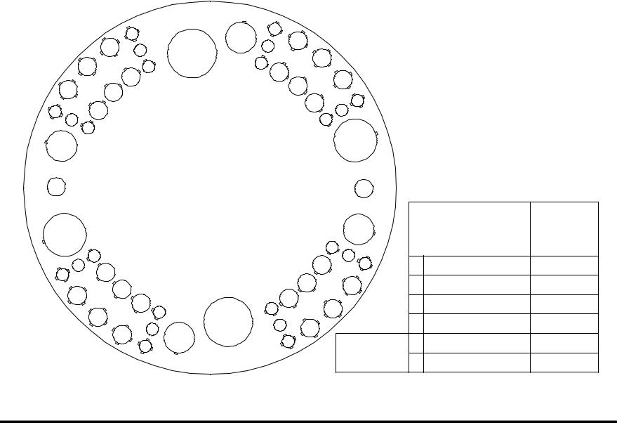
58 Station - 4 Auto-Index Turret Configuration
|
|
314 |
216 |
319 |
|
|
|
321 |
|
||
|
311 |
115 |
|
218 |
|
|
213 |
|
|
||
309 |
A/I |
117 |
323 |
|
|
112 |
|
120 |
|
||
|
|
110 |
|
325 |
|
307 |
|
|
122 |
||
108 |
|
|
|
||
|
|
124 |
227 |
||
204 |
106 |
|
|
||
|
|
126 |
328 |
||
305 |
103 |
|
|
|
|
|
|
|
|
||
|
|
|
|
|
|
202 |
229 |
|
1200mm disk |
||
|
|
|
|
58 STATION |
|
|
230 |
|
|
|
|
A/I |
|
|
4 AUTO INDEX |
|
A/I |
|
|
|
||
201 |
|
VIPROS 358 KING VIPROS 368 KING |
|
|
|
|
||||
|
|
|
VIPROS 558 VIPROS 568 |
|
|
|
|
Number of |
||
|
|
|
|
PEGA 358S |
|
|
231 |
|
Maximum |
Stations |
258 |
|
|
|
|
|
|
|
Size Round |
(Keyed) |
|
|
|
|
|
|
132 |
|
|
|||
|
155 |
|
|
|
334 |
|
|
|
||
357 |
|
|
|
135 |
|
|
|
|||
153 |
|
|
|
233 |
A |
½" (12.7mm) |
24 (16) |
|||
256 |
|
|
|
137 |
336 |
1¼" (31.7mm) |
24 (24) |
|||
354 |
|
151 |
|
|
139 |
B |
||||
|
|
149 |
|
|
|
C |
2" (50.8mm) |
4 (4) |
||
|
|
|
144 |
141 |
338 |
|||||
|
352 |
|
146 |
|||||||
|
247 |
|
242 |
340 |
|
D |
3½" (88.9mm) |
2 (2) |
||
|
|
A/I |
|
|||||||
|
|
350 |
245 |
343 |
|
|
B |
1¼" (31.7mm) |
2 (2) |
|
|
|
|
|
|
||||||
|
|
|
348 |
|
|
|
Auto Index |
|||
|
|
|
|
|
|
E |
4½" (114.3mm) |
2 (2) |
||
|
|
|
|
|
|
|
|
|||
Print Date 11/05/97 |
Page 8 of 41 |
This document available on the World Wide Web at http://amada.com/support/pdf/v358kuig.pdf |
|

Vipros 358 King User Pre-installation Guide |
|
Amada America Inc. |
||||
|
|
Fanuc O4PC CNC Controller |
|
|
||
|
|
|
|
|||
|
|
|
|
|
|
|
|
|
|
|
|
|
|
|
|
|
Model |
|
Fanuc O4PC |
|
|
|
|
|
|
|
|
|
|
|
Control Function |
|
X, Y, T & C |
|
|
|
|
|
|
|
|
|
|
|
Input Method |
|
MDI, Paper Tape, DNC |
|
|
|
|
|
|
|
|
|
|
|
Minimum Command |
|
0.001" (X, Y) .010 (C) |
|
|
|
|
Unit |
|
|
|
|
|
|
|
|
|
|
|
|
|
Minimum Travel Unit |
|
0.001" (X, Y) .010 (C) |
|
|
|
|
Operating Modes |
|
Automatic, MDI & Manual |
|
|
|
|
|
|
|
|
|
|
|
Display Modes |
|
Program Contents, Position Information, |
|
|
|
|
|
|
Program Check, Parameters, Tool Hit |
|
|
|
|
|
|
Counter, Self Diagnostics |
|
|
|
|
|
|
|
|
|
|
|
Interlock Displays |
|
Oil Temperature, Door Open |
|
|
|
|
|
|
|
|
Print Date 11/05/97 |
Page 9 of 41 |
This document available on the World Wide Web at http://amada.com/support/pdf/v358kuig.pdf |
|

Vipros 358 King User Pre-installation Guide |
Amada America Inc. |
 Supply Requirements
Electrical Power Supply |
Vipros 358 King |
230 / 460 3ph ±10%, 28 kVA |
|
SBC-5.5 Chiller* |
230 or 460 3ph ±10%, 15 kVA |
|
|
|
Air Supply |
|
80 psi @ 8.8 ft³/min. |
|
|
|
*Voltage must be specified when machine is ordered
Print Date 11/05/97 |
Page 10 of 41 |
This document available on the World Wide Web at http://amada.com/support/pdf/v358kuig.pdf |
|

Vipros 358 King User Pre-installation Guide |
Amada America Inc. |
Installing the Electrical Power Supply
The Vipros 358 King requires two electrical power sources. The first power source is supplied to the Fanuc O4PC control. The Fanuc O4PC control should be supplied from a power line separate from those used for welding machines or other machines that produce electrical noise. The second source is connected to the SBC-5.5 chiller.
The Vipros 358 King electrical inlet is 60" above floor level inside the magnetic enclosure located to the rear of the Fanuc O4PC control.
The SBC-5.5 chiller electrical inlet is 48" above floor level at the end of the chiller.
Vipros King |
SBC 5.5 Chiller |
Print Date 11/05/97 |
Page 11 of 41 |
This document available on the World Wide Web at http://amada.com/support/pdf/v358kuig.pdf |
|
Vipros 358 King User Pre-installation Guide |
Amada America Inc. |
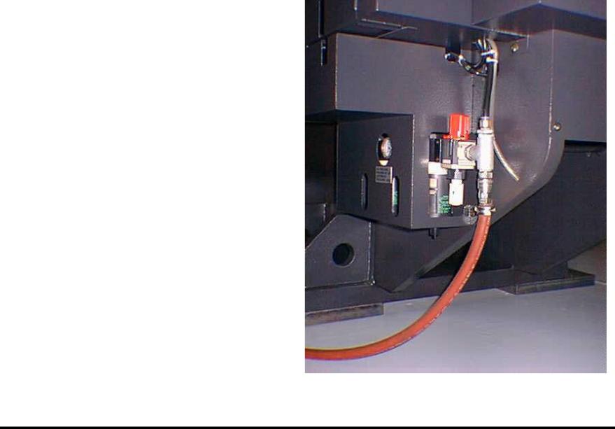
Installing the Air Supply
The Vipros 358 King must be connected to a compressed air system by hose or pipe. The compressed air must be clean and dry.
Please note the following:
The minimum inner pipe diameter is ½".
The air pressure required is 80 psi.
The air volume required is 8.8 ft³/min.
The air inlet is approximately 16" above the floor level at the rear of the Vipros 358 King.
Print Date 11/05/97 |
Page 12 of 41 |
This document available on the World Wide Web at http://amada.com/support/pdf/v358kuig.pdf |
|

Vipros 358 King User Pre-installation Guide |
Amada America Inc. |
 Planning the Location of the Vipros 358 King
The following diagrams provide the details for positioning the Vipros 358 King.
No obstacles are allowed in the worksheet travel area and the ceiling must be at least 40" above the top of the Vipros 358 King.
All of the maintenance areas recommended should be used, but at a minimum you must ensure that the doors of the Fanuc O4PC CNC unit can be opened.
The Vipros 358 King, Fanuc O4PC control, and SBC-5.5 chiller must be protected from direct sunlight or other heat sources.
The floor must be of sufficent quailty to addiquitly support the wieght of the machine. See Floor Mounting Procedure for details.
Print Date 11/05/97 |
Page 13 of 41 |
This document available on the World Wide Web at http://amada.com/support/pdf/v358kuig.pdf |
|
 Loading...