


QUICKSTART GUIDE
ENGLISH ( 2 – 4 )
MANUAL DE INICIO RÁPIDO
ESPAÑOL ( 5 – 7 )
GUIDE D’UTILISATION RAPIDE
FRANÇAIS ( 8 – 10 )
GUIDA RAPIDA
ITALIANO ( 11 – 13 )
SCHNELLSTART-ANLEITUNG
DEUTSCH ( 14 – 16 )
SNELSTARTGIDS
NEDERLANDS ( 17 – 19 )

BOX CONTENTS
yZEPHYR mixer
yPower adapter
yQuickstart Guide
ySafety Instructions & Warranty Information booklet
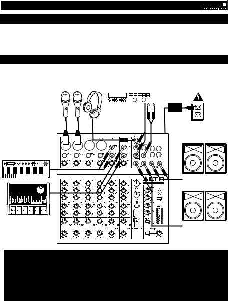
CONNECTION DIAGRAM
Headphones* |
External effects rack, |
compressor, etc.*
Microphones* |
|
|
Power |
|
House Speakers* |
Keyboard* |
|
|
2 TK |
Drum Machine* |
2 TK |
|
|
2 TK |
Monitors* |
*not included
Notes:
yMicrophones, monitors, amplifier, speakers, cables, etc. are not included.
yTo reduce electrical hum at high gain settings, keep the mixer's power supply away from your guitar cable and the mixer's channel inputs.
yTo use an external effects rack unit, compressor, etc., use a Y-cable (1/4" stereo to two 1/4" mono) to connect the AUX SEND "2 FX" output to the left and right inputs your external device. Connect the outputs of your external device to the left and right AUX RETURN INPUTS.
2
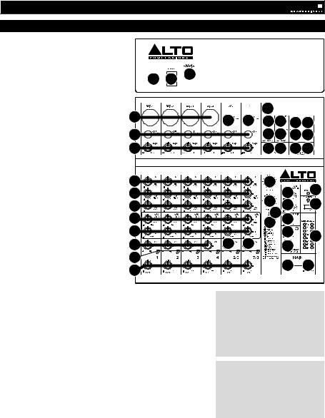
FEATURES
1.POWER IN – Use the included power adapter to connect the mixer to a power
|
outlet. While the power is switched off, |
|
|
|
|
|
|
plug the power supply into the mixer |
|
|
|
|
|
|
first, then plug the power supply into a |
|
|
3 |
|
|
|
power outlet. |
1 |
2 |
|
|
|
2. |
POWER SWITCH – Turns the mixer on |
|
|
|
||
|
|
|
|
|
||
|
and off. Turn on the mixer after all |
|
|
|
|
|
|
input devices have been connected and |
|
|
|
|
|
|
before you turn on amplifiers. Turn off |
|
|
|
|
22 |
|
amplifiers before you turn off the mixer. |
|
|
|
|
|
3. |
FOOTSWITCH – When a latching-style |
4 |
|
5 |
5 |
1617 1819 |
|
footswitch is connected to this jack with |
|
|
|||
|
|
|
|
|
|
|
|
a 1/4" TRS cable, it can be pressed to |
5 |
|
|
|
1617 1819 |
|
allow all channels to bypass the mixer's |
|
|
|
|
2 TK |
|
internal effects processor. |
6 |
|
|
|
2020 21 21 |
4. |
MIC INPUT – Connect a microphone to |
|
|
|
||
|
|
|
|
|
||
|
these inputs with an XLR cable. |
|
|
|
|
|
5.LINE INPUT * – Connect line-level
|
devices to these inputs with 1/4" cables. |
7 |
|
23 |
|
|
|
6. |
GAIN – Adjusts the channel audio level |
|
|
35 |
|||
|
(pre-fader and pre-EQ gain). |
Adjust |
8 |
|
|
26 |
|
|
|
|
|
||||
|
this so that the PEAK LED just barely |
|
24 |
|
34 |
||
|
lights up during the loudest parts of the |
9 |
|
27 |
|||
|
song. |
|
|
|
14 |
|
|
7. |
HI EQ (TREBLE) – Adjusts the high |
10 |
|
25 |
28 |
|
|
|
(treble) frequencies of the channel. |
11 |
|
|
29 |
|
|
8. |
MID EQ – Adjusts the mid-range |
|
|
33 |
|||
|
frequencies of the channel. |
|
12 |
13 |
13 |
30 |
|
|
|
|
|
|
|
2 TK |
|
9. |
LOW EQ (BASS) – Adjusts the low |
|
|
|
|
|
|
|
(bass) frequencies of the channel. |
14 |
|
|
|
|
|
10. |
AUX SEND 1 MON – Adjusts the |
15 |
|
|
31 |
32 |
|
|
channel audio (pre-EQ) level that is |
|
|
2 TK |
|
||
|
|
|
|
|
|||
|
sent to the AUX SEND output labeled |
|
|
|
|
|
|
|
"1 MON." You can use this to create a |
|
|
|
|
|
|
|
custom monitor mix for yourself or your musicians. |
|
|
|
|
||
11. |
AUX SEND 2 FX – Adjusts the channel audio (post-EQ) level that is sent |
* When using LINE INPUTS 5/6, 7/8, |
|
and the AUX RETURNS: |
|||
|
to the mixer's internal effects processor. Turn this up for the channels that |
||
|
• If only the left channel is used, the |
||
|
you want internal effects applied to. You can use this to apply external |
||
|
effects to individual channels. |
signal will be heard in both left and |
|
|
right channels and the balance will |
||
12. |
CHANNEL PAN – Adjusts the (mono) channel's position in the stereo |
||
not be adjustable. |
|||
|
field. |
• If only the right channel is used, the |
|
13. |
BALANCE (CH 5/6 & 7/8) – Adjusts the balance between Channels 5 and |
signal will be heard in the right |
|
|
6 and Channels 7 and 8. |
channel only. |
14.PEAK LED – The LED will flash if the signal is clipping. If this happens,
decrease the setting of the GAIN knob or CHANNEL VOLUME knob. |
** To use an external effects rack unit, |
|||||
15. CHANNEL VOLUME – Adjusts the audio level on the channel. |
compressor, etc., use a Y-cable (1/4" |
|||||
16. AUX RETURN INPUTS ** – You can connect the outputs of an external |
stereo to two 1/4" mono) to connect the |
|||||
AUX SEND "2 FX" output to the left and |
||||||
device to these inputs with 1/4" mono cables. This is usually used for |
||||||
right |
inputs |
your |
external |
device. |
||
outboard effects devices but can also be used like an extra input channel |
||||||
Connect the |
outputs |
of your |
external |
|||
for synthesizers, drum machines, etc. If your source is mono, plug it into |
||||||
device |
to the left |
and right AUX |
||||
the left jack and it will be heard on both the left and right sides. |
||||||
RETURN INPUTS. |
|
|
||||
|
|
|
||||
17.AUX SEND OUTPUTS ** – You can use a 1/4" TRS cable to connect the
AUX 1 MON output to the input of an external amplifier or active monitor to create a custom monitor mix for onstage musicians. You can adjust this level with the AUX RETURN LEVEL knob labeled "TO AUX 1 MON." To use an external effects rack unit, compressor, etc. with the mixer, you can use a Y-cable to connect the AUX 2 FX output to the input of your external device, then connect the outputs of the device to the AUX RETURN INPUTS of the mixer.
18.2-TRACK INPUTS – You may connect these inputs to the outputs of an external sound source using a standard stereo RCA cable (sold separately). You can send this channel to the monitor mix (using the MAIN/2-TRACK switch) and/or the main mix (using the 2-TRACK TO MAIN switch).
19.2-TRACK OUTPUTS – You may connect these outputs to the inputs of an external recording device using a standard stereo RCA cable (sold separately).
20.CTRL ROOM OUTPUTS – Use standard 1/4" cables to connect these outputs to your monitor or amplifier system. The level of these outputs is controlled by the CTRL ROOM / PHONES knob.
21.MAIN MIX OUTPUTS – Use standard 1/4" cables to connect these outputs to the house speaker or amplifier system. The level of these outputs is controlled by the MAIN VOLUME knob.
22.PHONES – Connect your 1/4" stereo headphones to this output. The CTRL ROOM / PHONES knob controls the volume.
3

23.EFFECTS SELECTOR – Selects the effect that the mixer's internal effects processor will apply to the various channels. Each channel can send different levels of audio to the processor by adjusting their FX POST SEND knobs. See the EFFECTS section for an explanation of the available effects.
24.VARIATIONS SELECTOR – Selects the amount of the effect applied to the various channels.
25.FX MUTE – Press this button to mute/unmute the effects.
26.AUX RETURN TO MAIN MIX – Adjusts the volume of the signal being sent into the AUX RETURN INPUTS and routed to the MAIN MIX OUTPUTS.
27.AUX RETURN TO AUX 1 MON – Adjusts the volume of the signal being sent into the AUX RETURN INPUTS and routed to the CTRL ROOM OUTPUTS.
28.2-TRACK LEVEL – Adjusts the input signal level of the 2-TRACK INPUTS.
29.CTRL ROOM / PHONES – Adjusts the volume of the CTRL ROOM OUTPUTS and your headphones.
30.MAIN / 2-TRACK – Press this button to select which signal is routed to the CTRL ROOM OUTPUTS and your headphones – the main mix or the signal from the 2-TRACK INPUTS.
31.2-TRACK TO MAIN – Press this button to select which signal is routed to the MAIN MIX OUTPUTS – the main mix or the signal from the 2-TRACK INPUTS.
32.MAIN VOLUME – Adjusts the volume of the MAIN OUT.
33.LED METERS – Shows the audio level of the main mix. Turn the volume down if the CLIP LED lights up excessively.
34.PHANTOM POWER – This switch activates and deactivates phantom power. When activated, phantom power supplies +48V to the XLR mic inputs and the LED above the switch will be lit. Please note that most dynamic microphones do not require phantom power, while most condenser microphones do. Consult your microphone’s documentation to find out whether it needs phantom power.
35.POWER LED – Illuminates when the mixer is on.
EFFECTS
TO HEAR THE EFFECTS ON A CHANNEL: Use the EFFECTS SELECTOR to choose one of the effects below, adjust the parameter with the VARIATIONS SELECTOR, then turn up the FX POST SEND for that channel.
|
# |
|
PRESET |
|
DESCRIPTION |
|
PARAMETER |
|
RANGE |
|
|
|
|
|
|||||
1 |
|
VOCAL 1 |
Reverb, simulating a room with a small delay time. |
|
Decay time |
|
0.8~1.1s |
||
|
|
Pre-delay |
|
0~79ms |
|||||
|
|
|
|
|
|
|
|
||
|
|
|
|
|
|
|
|
|
|
2 |
|
VOCAL 2 |
|
Reverb, simulating a small space with a slight decay |
|
Decay time |
|
0.8~2.5s |
|
|
|
time. |
|
Pre-delay |
|
0~79ms |
|||
|
|
|
|
|
|
|
|||
|
|
|
|
|
|
|
|
|
|
3 |
|
LARGE HALL |
Reverb, simulating a large acoustic space. |
|
Decay time |
|
3.6~5.4s |
||
|
|
Pre-delay |
|
23~55ms |
|||||
|
|
|
|
|
|
|
|
||
|
|
|
|
|
|
|
|
|
|
4 |
|
SMALL HALL |
Reverb, simulating the acoustics of a stage space. |
|
Decay time |
|
1.0~2.9s |
||
|
|
Pre-delay |
|
20~45ms |
|||||
|
|
|
|
|
|
|
|
||
|
|
|
|
|
|
|
|
|
|
5 |
|
LARGE ROOM |
Reverb, simulating a studio with many early reflections. |
|
Decay time |
|
2.9~4.5s |
||
|
|
Pre-delay |
|
23~55ms |
|||||
|
|
|
|
|
|
|
|
||
|
|
|
|
|
|
|
|
|
|
6 |
|
SMALL ROOM |
Reverb, simulating a bright studio room. |
|
Decay time |
|
0.7~2.1s |
||
|
|
Pre-delay |
|
20~45ms |
|||||
|
|
|
|
|
|
|
|
||
|
|
|
|
|
|
|
|
|
|
7 |
|
PLATE |
|
Simulates bright plate reverb. |
|
Decay time |
|
0.6~6.1s |
|
|
|
|
Pre-delay |
|
10ms |
||||
|
|
|
|
|
|
|
|
||
|
|
|
|
|
|
|
|
|
|
8 |
|
TAPE REVERB |
|
Simulates classic tape delay created by multiple |
|
Decay time |
1.3~5.4 |
||
|
|
playback heads. |
|
Pre-delay |
|
0~84ms |
|||
|
|
|
|
|
|
|
|||
|
|
|
|
|
|
|
|
|
|
9 |
|
SPRING REVERB |
|
Simulates the lightly stretched sound of spring reverb |
|
Decay time |
|
1.3~5.4s |
|
|
|
from analog transducers. |
|
Pre-delay |
|
0~84ms |
|||
|
|
|
|
|
|
|
|||
|
|
|
|
|
|
|
|
||
10 |
|
MONO DELAY |
Reproduces the signal after a small period of time. |
|
Delay period |
|
60~650ms |
||
|
|
|
|
|
|
|
|
|
|
11 |
|
STEREO DELAY |
|
Reproduces the signal after a small period of time with a |
|
Delay period |
|
210~400ms |
|
|
|
slight difference between the two stereo channels. |
|
Feedback |
37~73% |
||||
|
|
|
|
|
|
||||
|
|
|
|
|
|
|
|
|
|
12 |
|
FLANGER |
|
Classic stereo flanging effect, similar to a jet plane |
|
Rate |
|
0.16~2.79Hz |
|
|
|
taking off. |
|
|
|||||
|
|
|
|
|
|
|
|
|
|
|
|
|
|
|
|
|
|
|
|
13 |
|
CHORUS |
|
Simulates the full, complex, watery sound of several |
|
Rate |
|
0.5~5Hz |
|
|
|
instruments playing the same thing. |
|
|
|||||
|
|
|
|
|
|
|
|
|
|
|
|
|
|
|
|
|
|
|
|
14 |
|
REVERB+DELAY |
Delay effect with room reverb. |
|
Delay period |
|
211~375ms |
||
|
|
Reverse decay time |
|
1.0~2.9s |
|||||
|
|
|
|
|
|
|
|
||
|
|
|
|
|
|
|
|
|
|
15 |
|
REVERB+FLANGER |
|
Stereo flanger effect with room reverb. |
|
Flanger rate |
|
0.16~2.52Hz |
|
|
|
|
Reverse decay time |
|
|||||
|
|
|
|
|
|
|
|
|
|
|
|
|
|
|
|
|
|
|
|
16 |
|
REVERB+CHORUS |
|
Stereo chorus effect with room reverb. |
|
Chorus rate |
|
0.5~4.74Hz |
|
|
|
|
Reverse decay time |
|
1.5~2.9s |
||||
|
|
|
|
|
|
|
|
||
|
|
|
|
|
|
|
|
|
|
4
CONTENIDO DE LA CAJA
yMezclador ZEPHYR
yAdaptador de alimentación
yGuía de inicio rápido
yFolleto de instrucciones de seguridad e información sobre la garantía
DIAGRAMA DE CONEXIÓN
|
Rack de efectos, |
|
Auriculares* |
compresor, etc. |
Suministro |
Micrófonos* |
externo* |
eléctrico |
|
|
Altavoces del |
|
|
auditorio* |
Teclado* |
|
2 TK |
Caja de ritmos* |
|
2 TK |
|
2 TK |
Monitores* |
* no incluido |
|
|
Notas: |
|
|
yNo se incluyen micrófonos, amplificador, altavoces, cables, etc.
yPara reducir el zumbido eléctrico cuando se usan ajustes altos de ganancia, mantenga la fuente de alimentación del mezclador alejada del cable de su guitarra y de las entradas de los canales del equipo.
yPara usar una unidad de rack de efectos, compresor, etc. externos, utilice un cable en “Y” (estéreo de 1/4"a dos mono de 1/4") para conectar la salida de ENVÍO AUXILIAR "2 FX" a las entradas izquierda y derecha de su dispositivo externo. Conecte las salidas de su dispositivo externo a las ENTRADAS DE RETORNO AUXILIAR izquierda y derecha.
5
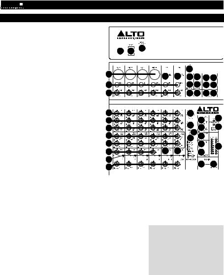
CARACTERÍSTICAS
1.ENTRADA DE ALIMENTACIÓN - Use el
|
adaptador de alimentación incluido para conectar |
|
|
|
|
|
|
el mezclador a un tomacorriente alimentado. |
|
|
|
|
|
|
Con la alimentación eléctrica desconectada, |
|
|
|
|
|
|
enchufe la fuente de alimentación al mezclador |
1 |
2 |
3 |
|
|
|
primero, y luego al tomacorriente. |
|
|
|
||
2. |
INTERRUPTOR DE ENCENDIDO – Enciende y |
|
|
|
|
|
|
apaga el mezclador. Encienda el mezclador |
|
|
|
|
|
|
después de desconectar todos los dispositivos |
|
|
|
|
22 |
|
de entrada y antes de encender los |
4 |
|
|
|
|
|
amplificadores. Apague los amplificadores antes |
|
5 |
5 |
1617 1819 |
|
|
de apagar el mezclador. |
|
|
3. |
INTERRUPTOR DE PEDAL – Cuando se |
5 |
|
1617 1819 |
||
|
conecta a este conector un interruptor de pedal |
|
|
|
|
2 TK |
|
de tipo de enganche con un cable TRS de 1/4", |
6 |
|
2020 21 21 |
||
|
se puede pulsar para permitir que todos los |
|
|
|
|
|
|
canales puenteen el procesador de efectos |
|
|
|
|
|
|
interno del mezclador. |
|
|
|
|
|
4. |
ENTRADA DE MICRÓFONO – Conecte a estas |
7 |
|
23 |
|
|
|
entradas un micrófono con un cable XLR. |
|
|
|
26 |
35 |
5. |
ENTRADA DE LÍNEA * – Conecte a estas |
8 |
|
|
||
|
|
|
||||
|
entradas dispositivos de nivel de línea con |
9 |
|
24 |
27 |
34 |
|
cables de 1/4”. |
|
|
14 |
|
|
6. |
GANANCIA - Ajusta el nivel de ganancia de |
10 |
|
28 |
|
|
|
25 |
|
||||
|
audio del canal (preecualización y pre-fader). |
|
|
|
|
|
|
Ajuste este control de modo que el LED PEAK |
11 |
|
|
29 |
33 |
|
apenas se encienda durante las partes más |
|
|
|
|
|
|
12 |
13 |
13 |
2 TK |
|
|
|
sonoras del tema. |
30 |
|
|||
7. |
ECUALIZACIÓN DE ALTOS (AGUDOS) – |
14 |
|
|
|
|
|
Ajusta las altas frecuencias (agudos) del canal. |
|
|
|
31 |
32 |
8. |
ECUALIZACIÓN DE MEDIOS – Ajusta las |
15 |
|
|
||
|
|
|
|
|
2 TK |
|
|
frecuencias medias del canal. |
|
|
9. |
ECUALIZACIÓN DE BAJOS (GRAVES) – |
|
|
|
|
||
|
|
||
|
Ajusta las bajas frecuencias (graves) del canal. |
|
|
10. |
ENVÍO AUXILIAR 1 MON – Ajusta el nivel de audio del canal (pre- |
*Cuando use las ENTRADAS DE LÍNEA |
|
|
ecualización) que se envía a la salida de ENVÍO AUXILIAR rotulada “1 |
5/6, 7/8 y los RETORNOS AUXILIARES: |
|
|
MON”. Puede usarlo para crear una mezcla de monitor personalizada |
• Si sólo se usa el canal izquierdo, la |
|
|
para usted mismo o para sus músicos. |
señal se oirá en los canales izquierdo |
|
11. |
ENVÍO AUXILIAR 2 FX – Ajusta el nivel de audio del canal (post- |
y derecho y no se puede ajustar el |
|
|
ecualización) que se envía al procesador de efectos interno del |
balance. |
|
|
mezclador. Aumente el ajuste para los canales a los que desea aplicar |
• Si sólo se usa el canal derecho, la |
|
|
efectos internos. Puede usarlo para aplicar efectos externos a canales |
||
|
señal se oirá sólo en ese canal. |
||
|
individuales. |
|
|
|
|
||
12. |
PANEO DE CANAL – Ajusta la posición del canal (mono) en el campo |
** Para usar una unidad de rack de |
||
|
estéreo. |
|
||
|
|
efectos, compresor, etc. externos, utilice |
||
13. |
BALANCE (CANALES 5/6 Y 7/8) – Ajusta el balance entre los canales 5 |
|||
un cable en “Y” (estéreo de 1/4"a dos |
||||
|
y 6 y los canales 7 y 8. |
|
||
|
|
mono de 1/4") para conectar la salida de |
||
14. |
LED DE PICO – El LED destella si la señal se está recortando. |
Si esto |
||
ENVÍO AUXILIAR "2 FX" a las entradas |
||||
|
sucede, disminuya el ajuste de la perilla GAIN o la perilla de volumen |
|||
|
izquierda y derecha de su dispositivo |
|||
|
CHANNEL (Canal) . |
|
||
|
|
externo. Conecte las salidas de su |
||
15. |
VOLUMEN DE CANAL – Ajusta el nivel de audio del canal. |
|
||
|
dispositivo externo a las ENTRADAS DE |
|||
16. |
ENTRADAS DE RETORNO AUXILIAR ** – Puede conectar |
a estas |
||
RETORNO AUXILIAR izquierda y |
||||
|
|
|
||
entradas las salidas de un dispositivo externo con cables mono de 1/4". derecha. Esta entrada se usa habitualmente para dispositivos de efectos externos
pero también se puede usar como canal de entrada adicional para
sintetizadores, cajas de ritmo, etc. Si su fuente es mono, enchúfela en el conector izquierdo y se escuchará en ambos lados, izquierdo y derecho.
17.SALIDAS DE ENVÍO AUXILIAR ** – Puede usar un cable TRS de 1/4" para conectar la salida AUX 1 MON a la entrada de un amplificador externo o monitor activo a fin de crear una mezcla de monitor personalizada para los músicos en el escenario. Puede ajustar este nivel con la perilla de NIVEL DE RETORNO AUXILIAR rotulada "TO AUX 1 MON". Para usar una unidad de rack de efectos, compresor, etc. externos con el mezclador, puede usar un cable en “Y” a fin de conectar la salida AUX 2 FX a la entrada de su dispositivo externo y luego conectar las salidas de este último a las ENTRADAS DE RETORNO AUXILIAR del mezclador.
18.ENTRADAS DE 2 PISTAS – Es posible conectar estas entradas a las salidas de una fuente de sonido externa mediante un cable RCA estéreo estándar (se vende por separado). Puede enviar este canal a la mezcla de monitor (mediante el interruptor MAIN/2-TRACK [PRINCIPAL/2 PISTAS]) y/o la mezcla principal (mediante el interruptor 2- TRACK TO MAIN [2 PISTAS A PRINCIPAL]).
19.SALIDAS DE 2 PISTAS – Es posible conectar estas salidas a las entradas de un dispositivo de grabación externa mediante un cable RCA estéreo estándar (se vende por separado).
20.SALIDAS PARA SALA DE CONTROL – Use cables estándar TRS de 1/4" para conectar estas salidas al sistema de amplificador o monitores. El nivel de estas salidas se controla mediante la perilla CTRL ROOM / PHONES (SALA DE CONTROL / AURICULARES).
21.SALIDAS DE MEZCLA PRINCIPAL – Use cables estándar TRS de 1/4" para conectar estas salidas al sistema de amplificador o altavoces. El nivel de estas salidas está controlado por la perilla de VOLUMEN MAESTRO.
6
 Loading...