


PS-2

www.altoproaudio.com
Version 1.0
MODEL: PS 2/2A

1. Introduction
These cabinets is designed for professional stage performance . The special
handle shows unique Italy style. With the accurate crossover point made the
timbre very clean.
It adopt special horn in polypropylene reinforced. With wide directional angle
90°H ± 45°V ( 1kHz - 16kHz), and PS 2TW AES 150Watt PEAK 300Watt .
Matching the 10” 6 Ohm 80-160W woofer with 15W 8 Ohm tweeter made the
acoustics of the cabinet clean and the bass strong. All these characters made
it very suitable for any place.
These cabinets is designed for professional stage performance . The special
handle shows unique Italy style. With the accurate crossover point made the
timbre very clean.
It adopt special horn in polypropylene reinforced. With wide directional angle
90°H ± 45°V ( 1kHz - 16kHz), and PS 2A LOW Output Power 150Watt Class
AB / HIGH Output Power 50Watt Class AB. All these characters made it very
suitable for any place. The main amplifier functions as following:
●One input volume control
●One set of Ø6.3 stereo MIC inlet
●One set of balanced outlet
●Clip indicators input signal level
●Overload & overheat protection.
PS2
PS2A
- 1 -
Technical Specification
PS2A
Active System Type Bi-Amp. With Analog Processor
LOW Output Power LOW 150Watt RMS Bridge Class AB
HIGH Output Power High 50Watt RMS Class AB
(Max SPL at 1W,1m) 118dB SPL Calculated
Frequency Response 55HZ/20KHZ +/-10dB
Impedance Low-High) Low 8 Ohm-High 8 Ohm
Crossover Frequency Complex EQ Processor
Protection Low-High Limiter/Compressor plus PTC
LOW-Frequency High-Frequency 10"/266mm-1.5" Voice Coil 1" Compression Driver 1" Voice Coil
Horn Coverage H -V 90° H* 45° V
Input Sensitivity Line +4dB/1.23V
Impedance 30kOhms Balanced -15kOhms Unbalanced
Connectors Input with Jack / Link with XLR
Plastic Reinforced Calinet Trapezoidal & Monitor Shape
Hardware Suspension Seven Suspension Point
Amplifier Protections Soft Start- Short Circuit-DC voltage -Thermal Protection
External Control Volume-Clip-Ground Switch
Power Supply 230Volt/115Volt 50/60Hz
Dimensions (H*W*D) H:595 mm (23.4") W: 320mm (12.6") D: 334.5mm(13.2")
Net Weight (Lbs/Kg) 27.6 lbs /12.52 kg
Gross Weight (Lbs/Kg) 33.88 lbs /15.37 kg
ShippingVolume 3.36CFT
Technical Specification
PS2 ( 2-way)
Passive System type 2-Way Vented box
Continuos Power Handling) 120Watt AES Standard
Peak Power Rating 240Watt Peak
SPL 1W,1m 96dB SPL
MAX SPL 1mt 117dB SPL Calculated
Frequency Response 60Hz ~ 20kHz ± 10dB
Impedance 8 Ohm Nominal
Crossover Frequency 2450Hz at 12dB/Oct
Low-Frequency 10" /266mm -1.5" Voice Coil
High-Frequency 1" Compression Driver 1" Voice Coil
Horn Coverage H -V 90°H ± 45°V ( 1kHz - 16kHz)
High Frequency Protection Electronic Dynamic Protection
Input Connectors Pin1+ ;Pin1-
Dimensions H: 395 mm (23.4") W: 320 mm (12.6") D: 334.5 mm(13.2")
Weight 21.38 lbs / 9.7 kg
Shipping Weight 27.67 lbs / 12.55 kg
Volume 3.36 CFT
2.Specification
- 2 -

CONTENT
1. Introduction.................................................................................................1
2. Specification...............................................................................................2
3. Block Diagram.............................................................................................3
4. Schematic Diagram....................................................................................5
5. PCB Layout...................................................................................................9
6. Exploded View & Mechanical Parts List............................................11
7. BOM..............................................................................................................15
1 2 3 4
A
B
C
D
4321
D
C
B
A
POWER SWITCH
MIX AMP
LOW POWER
HI POWER
AMP
AMP
LOW SPEAKER+
HI SPEAKER
V-
V+
AC INPUT
PT-2A-E
HPF
LPF
PS 2A BLOCK DIAGRAM
SIGNAL INPUT
VOLUME
LOW SPEAKER-
BRIDGE OUT+
BRIDGE OUT-
3.Block Diagram
- 3 -
1 2 3 4 5 6
A
B
C
D
654321
D
C
B
A
2-
1+
1-
2+
B
SPK2
2-
1+
1-
2+
B
SPK1
INPUT
CROSSOVER CIRCUIT
DRIVER SPEAKER
WOOFER SPEAKER
PS 2A BLOCK DIAGRAM
- 4 -
1 2 3 4 5 6 7 8
A
B
C
D
87654321
D
C
B
A
V+
1
NC
2
OUT
3
V-
4
V+
5
NC
6
GND
7
MUTE
8
-VIN
9
+VIN
10
NC
11
U1
LM3886
1
2
3
4
5
6
7
8
9
10
CN1
CN-5PX2-F
C22
0.1u
R11
10K
R3
1k
R12
220K
R1
10K
R2
560E
C14
560P
C12
0.1u
C5
0.1u
C13
10P
C19
10u/50V
V+
1
NC
2
OUT
3
V-
4
V+
5
NC
6
GND
7
MUTE
8
-VIN
9
+VIN
10
NC
11
U2
LM3886
R4
10K
R5
560E
C15
0.1u
C2
0.1u
C16
10P
C20
10u/50V
C3
100u/50V
C9
100u/50V
C1
100u/50V
C8
100u/50V
T2
LOW BRIDGE+
T1
LOW BRIDGE-
C7
220u/16V
R7
10K
R18
470K
R17
1K
Z1
8V2
Q1
BC327
R16
10K
D1
VTL5C4
-Vc
-Vc
-Vc
+Vc
+Vc
T6
Vac
T8
GND
T7
Vac
C28
0.1u/275V
BR1
BU10-04
C27
6800u/50V
C26
6800u/50V
-Vc
+Vc
+Vc
-Vc
V+
1
NC
2
OUT
3
V-
4
V+
5
NC
6
GND
7
MUTE
8
-VIN
9
+VIN
10
NC
11
U3
LM3886
R15
33K
R10
0E
R14
22K
R8
27K
R9
150E
C17
0.1u
C6
0.1u
C18
10P
C4
100u/50V
C10
100u/50V
T3
HI OUT+
-Vc
+Vc
C23
220P
C25
820P
C11
56P
C24
0.1u
C21
0.01u
R13
10E
R6
10K
DS1
LAMP 2.1A
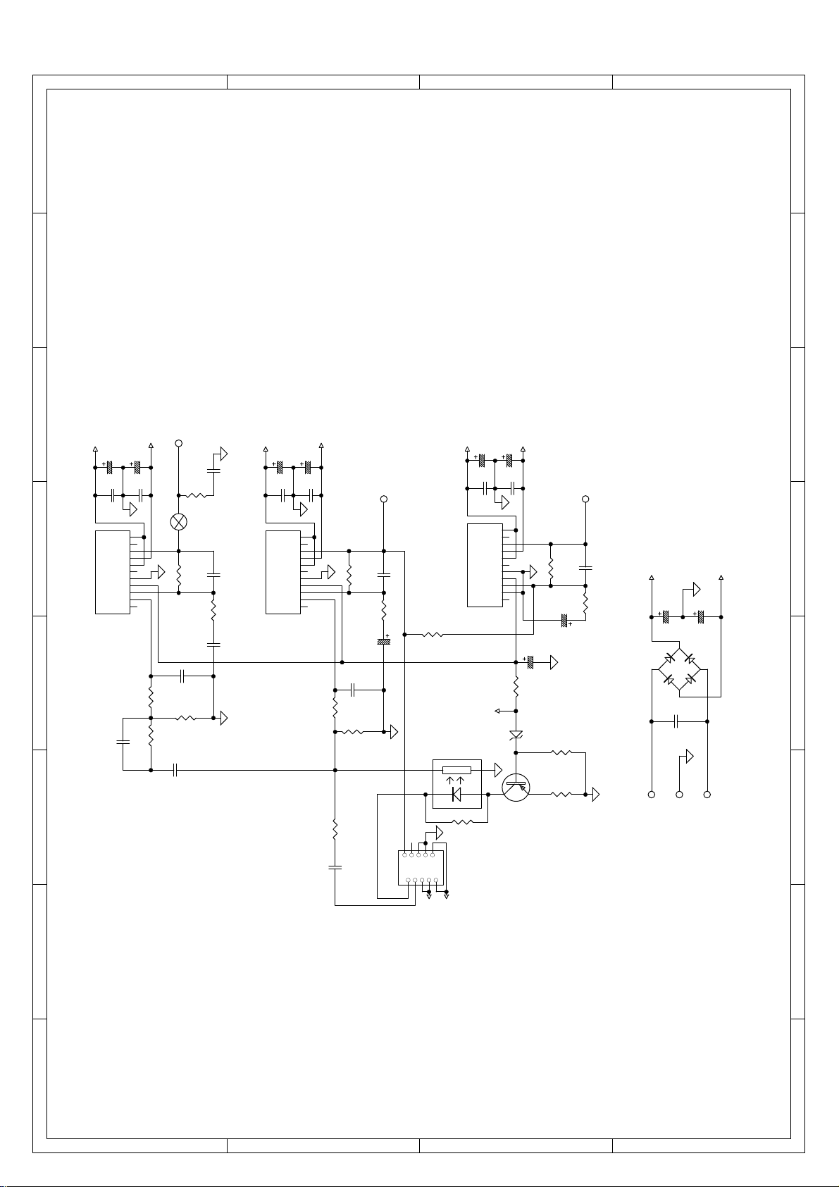
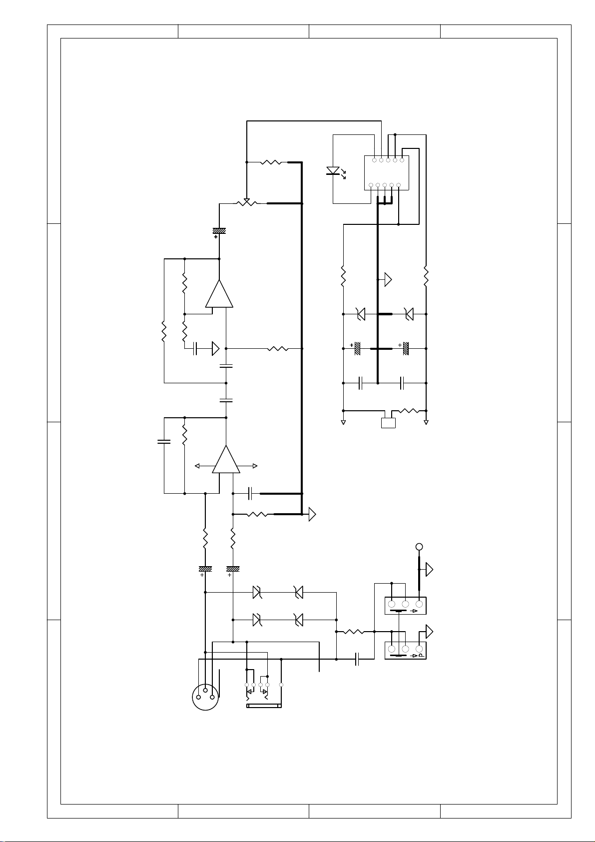
4.Schematic Diagram
PS2A
- 5 -
1 2 3 4
A
B
C
D
4321
D
C
B
A
2
1
3
4
J2
CN-BAL-MALE
Z5
15V1W
Z4
15V1W
Z6
15V1W
Z3
15V1W
R2
10K
R1
10K
R7
10K
R6
10K
C12
10P
C11
33P
C15
0.01uF/400V
R10
10E
1
2
3
SW1A
SW PS-22E85L
4
5
6
P
SW1B
SW PS-22E85L
GND
1
2
3
VR1
B50K
R3
56K
R12
10K
C1
22u/25V
C8
22u/25V
C14
10u/63V
R5
1K
R4
3K9
R8
680E
+15V
-15V
LINK
C2
0.22u
C4
0.15u
C13
22nF
1
2
3
48
+
_
U1A
NJM2068LD
+
_
U1B
NJM2068LD
1
2
3
4
5
6
7
8
9
10
J4
CN-5PX2-F
R12
820E 1W
R11
820E 1W
C10
220u/25V
C9
220u/25V
Z1
15V 1W
Z2
15V 1W
CLIP LED (RED)
D1
+15V
-15V
R13
15K 0.5W
1
2
CN1
TO PL
3c
5e
1a
4d
2b
J1
INPUT
C6
0.1u
C7
0.1u
PS2A
- 6 -
 Loading...