


Drive-2.3
R
English
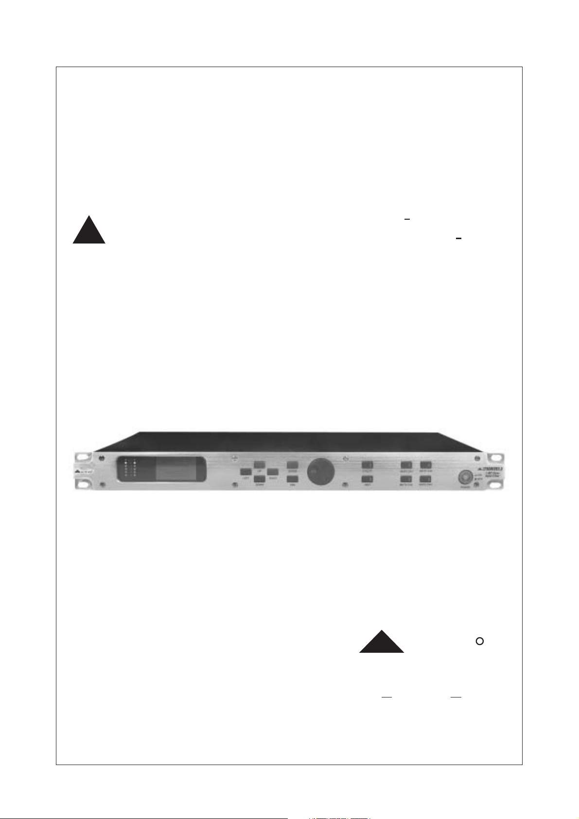
LTODRIVE2.3
User's Manual
2 WAY STEREO
DIGITAL X OVER
LTO
www.altoproaudio.com
Version 1.2 2003January

SAFETY RELATED SYMBOLS
CAUTION
RISK OF ELECTRIC SHOCK
DO NOT OPEN
This symbol, wherever it appears, alerts you
to the presence of uninsulated dangerous voltage
inside the enclosure-voltage that may be sufficient to constitute a risk of shock.
This symbol ,wherever it appears ,alerts you
to important operating and maintenance
instructions in the accompanying literature .
Read the manual .
Protective grounding terminal .
Alternating current /voltage .
Hazardous live terminal .
ON: Denotes the apparatus turns on .
OFF: Denotes the apparatus turns off ,because of
using the single pole switch ,be sure to unplug the
AC power to prevent any electric shock before you
proceed your service .
WARNING: Describes precautions that should
be observed to prevent the danger of injury or
death to the user .
CAUTION: Describes precautions that should
be observed to prevent danger of the apparatus .
WARNING
Power Supply
Ensure the source voltage matches the voltage of
the power supply before turning ON the apparatus.
Unplug this apparatus during lightning storms or when
unused for long periods of time .
External Connection
The external wiring connected to the output hazardous
live terminals requires installation by an instructed
person, or the use of ready-made leads or cords.
Do not Remove any Cover
There are maybe some areas with high voltages
inside , to reduce the risk of electric shock, do not
remove any cover if the power supply is connected.
The cover should be removed by the qualified personnel
only.
No user serviceable parts inside.
Fuse
To prevent a fire, make sure to use fuses with specified
standard (current, voltage, type). Do not use a different
fuse or short circuit the fuse holder.
Before replacing the fuse, turn OFF the andapparatus
disconnected the power source.
Protective Grounding
Make sure to connect the protective grounding to prevent
any electric shock before turning ON the apparatus.
Never cut off the internal or external protective grounding
wire or disconnect the wiring of protective grounding
terminal.
Operating Conditions
This apparatus shall not be exposed to dripping or
splashing and that no objects filled with liquids,
such as vases, shall be placed on this apparatus.
To reduce the risk of fire or electric shock, do not
expose this apparatus to rain or moisture.
Do not use this apparatus near water.
Install in accordance with the manufacturer's
instructions. Do not install near any heat sources
such as radiators, heat registers, stoves, or other
apparatus (including amplifiers) that produce heat.
Do not block any ventilation openings.
No naked flame sources, such as lighted candles,
should be placed on the apparatus.
IMPORTANT SAFETY INSTRUCTIONS
Read these instructions.
Follow all instructions.
Keep these instructions.
Heed all warnings.
Only use attachments/accessories specified by the
manufacturer.
Power Cord and Plug
Do not defeat the safety purpose of the polarized
or grounding type plug. A polarized plug has two
blades with one wider than the other. A grounding
type plug has two blades and a third grounding
prong. The wide blade or the third prong are provided
for your safety. If the provided plug does not fit into
your outlet, consult an electrician for replacement
of the obsolete outlet.
Protect the power cord from being walked on or
pinched particularly at plugs, convenience receptacles ,
and the point where they exit from the apparatus.
Cleaning
When the apparatus needs a cleaning, you can blow
off dust from the apparatus with a blower or clean
with rag etc. Don't use solvents such as benzol,
alcohol, or other fluids with very strong volatility and
flammability for cleaning the apparatus body.
Clean only with dry cloth.
Servicing
Refer all servicing to qualified personnel. To reduce
the risk of electric shock, do not perform any servicing
other than that contained in the operating instructions
unless you are qualified to do so .
Servicing is required when the apparatus has
been damaged in any way ,such as power supply
cord or plug is damaged , liquid has been spilled
or objects have fallen into the apparatus, the
apparatus has been exposed to rain or moisture,
does not operate normally, or has been dropped.
1

PREFACE
Dear Customer:
Thanks for choosing LTODRIVEand thanks for choosing one of the results of LTO AUDIO TEAM job
and researches.
For our LTO AUDIO TEAM , music and sound are more than a job... are first of all passion and let Us say
our obsession!
We have been designing professional audio products for a long time in cooperation with some of the major
Brands in the world in the audio field.
The LTO line presents unparalleled analogue and digital products made by Musicians for Musicians in our
R&D centers in Italy, Netherlands, United Kingdom and Taiwan. The core of our digital audio products
is a sophisticated DSP (digital sound processor) and a large range of state of the art algorithms which have
Been developed by our Software Team for the last 7 years.
Because we are convinced you are the most important member of LTO AUDIO TEAM and the one confirming
the quality of our job, we would like to share with you our work and our dreams, paying attention to your
suggestions and your comments.
Following this idea we create our products and we will create the new ones! From our side, we guarantee you and
we will guarantee you also in future the best quality , the best fruits of our continuous researches and the best
prices.
Our LTODRIVE is the result of many hours of listening and tests involving common people, area experts,
musicians and technicians; nothing else to add, but that we would like to thank all the people that made the
LTODRIVE a reality available to our customers , and thank our designers and all the LTO staff, people
who make possible the realization of products containing our idea of music and sound and are ready to
support you, our Customers, in the best way , conscious that you are our best richness.
Thank you very much
LTO AUDIO TEAM
2

TABLE OF CONTENTS
1. INTRODUCTION .......................................................................................... ..........4........
2. FEATURE LIST ..............................................................................................................4
3. .............................................FRONT AND BACK PANELS DESCRIPTION ........................4
3.1 The Front Panel
3.2 The Rear Panel
4. INSTALLATION & CONNECTION ............................................................... ............5.........
4.1 Power Up and Audio Connections
a. Audio Connections
b. Power Up Setting
4.2 Operational Overview
4.2.1 UTILITY MENU
a. Load Preset
b. Store Preset
c. MIDI Setup
d. VU-Meter
e. Password
4.2.2 EDIT MENU
a. Routing
b. IN L/IN R
c.OUT1/2/3/4/5/6
5. ......................................................APPLICATION ILLUSTRATION...................... .........12
5.1 LTODRIVE 2.3 2-Way Input, 4- Way Output (High, Mid, Low, Sub Level)
5.2
LTODRIVE2.3 2-Way Input, 4- Way Output (High, High, Low, Low Level)
6. ......................................................MIDI STANDARD CONTROL...................... ..............14
7. TECHNICAL SPECIFICATIONS ............................................................................ .........16
8. WARRANTY ........... ................................................................................. .....................18
3
1. INTRODUCTION
Thank you very much for expressing your confidence in LTO products by purchasing our LTODRIVE2.3.
With the LTODRIVE2.3 you have acquired an extremely musical and flexible Active Crossover which
will provide you also the subwoofer application.
Our new LTODRIVE 2.3(2 inputs , 4outputs , matrix-like operation X-over) allows the user to work
with the quality of the 2/3 by 24 32-bit DSPs, permits extremely precise and fast speakers control and
equalization for PA systems with the power of a matrix process allowing each kind of combination in
assigning the 2 inputs to the 4 outputs. The LTODRIVE 2.3 is based on 2/3 extremely powerful,
high-speed 24 32-bit DSP and very high quality 20-bit A/D and 24-bit D/A converters, preserving the
pureness of analogue sound in your digital applications. The 128 64 graphical display and the 12
buttons and the relative encoder available on the front panel, offer an easy way of editing data, so to
create new custom powerful and exciting presets which may then be stored in the unit as user's
presets . The integrated MIDI interface permits real-time editing with a powerful pc based SW or a
MIDI standard sequencer.
Both input channels feature a digital , high quality filters 5-band parametric equalizer, allowing boost
/attenuation of 15 dB in 0.5dB increment's steps. On each output channel is possible to have a 4
order low pass and a high pass filters, limiter /compressor and polarity switchable 0 or 180 .
2.FEATURE LIST
Single Rack Unit
Robust and Compact Design
24 32-bit High Speed Signal Processor
Open Architecture for Easy Software Updates
Windows Editor for Easy to Use and Powerful pc Based MIDI Remote Control
5 Parametric EQ for Each Channel
Band Pass Filter Available (Until 24dB/Oct) for Each Output Channel
Up to 0.5 sec. of Delay Per Channel by Step from 21 ms to 2ms
Lock-System for the Editing Functions
Manufactured Under ISO9001 Certified Management System
th
3.FRONT AND BACK PANELS DESCRIPTION
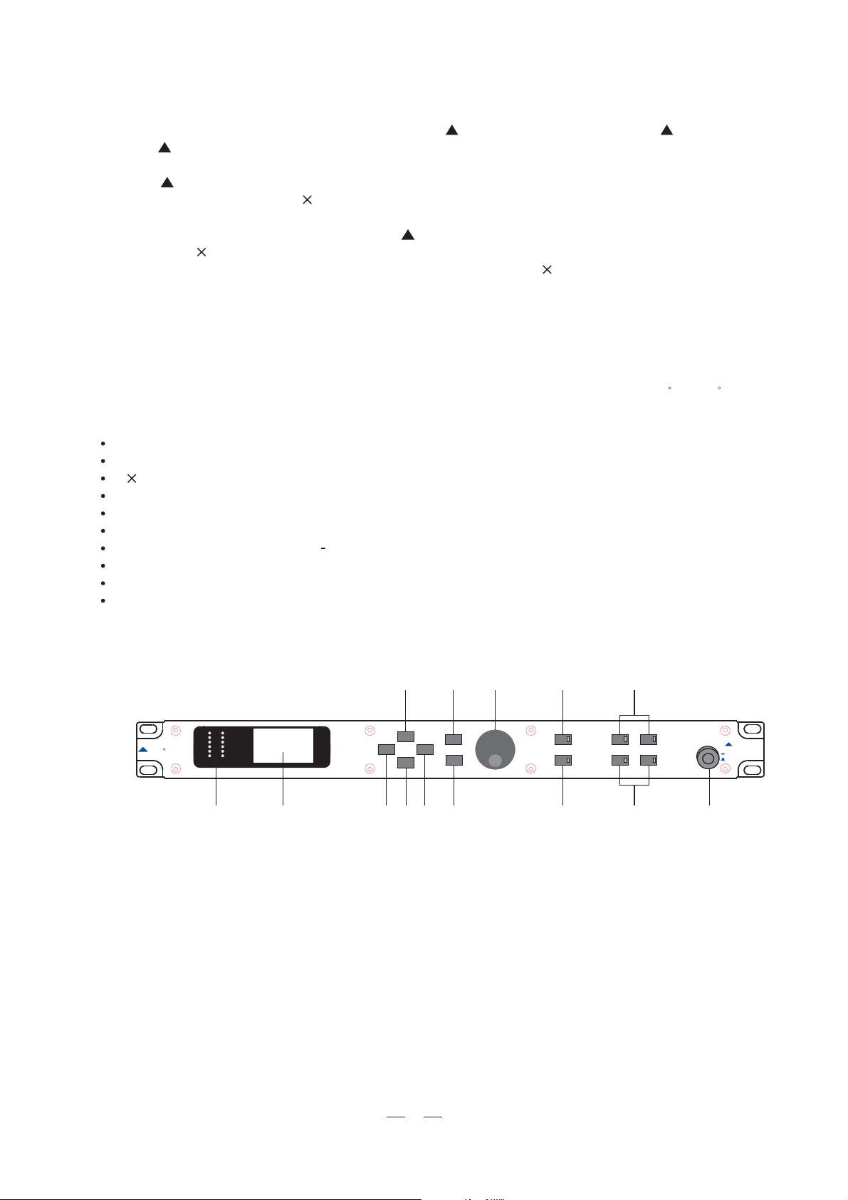
3.1.The Front Panel
CLIP
-6
12
LTO
1.Power SW with LED
2.Mute buttons and LEDs for CH1, CH2, CH3, CH4
3.Utility key and LED
4.Edit key and LED
5.Dial knob(encoder)
6.Enter key
7.ESC key
8.Up key
9.Right key
10.Down key
11.Left key
12.Graphic display
13.Vu-meters
18
24
30
LEFT
1213 2
865 3 2
DOWN
UP
RIGHT
ENTER
ESC
UT LITY
EDIT
MUTE CH1
MUTE CH2
MUTE CH3
MUTE CH4
41710 911
POWER
LTODRIVE2.3
2 WAY Stereo
ON
Digital X Over
OFF
4

Power SW with LED (1)
Turns the apparatus on and off. Press this SW, the power LED inside the SW will turn on.
Dial Control knob (5)
Used to change editable values.
3.2.The Rear Panel
AC INPUT
95-240V 60-50Hz
RatedPower Consumption 15W
FUSE
210-240V T250mAL 250VAC
95-120V 500mA 250VAC
REPLACEFUSE W TH CORRECT
TYPEONLY
Apparaten skallanslutas ti l
jordat uttagnar den ansluts
t llett natverk
MODEL
SERIAL
MIDI
INPUTTHRUOUTPUT
OUTPUT1OUTPUT2OUTPUT3OUTPUT4
PUSH
NEW TDE
3
21
PUSH
NEW TIDE
3
21
INPUT1INPUT2
17
16 15
14
14.Input Connector for Input1 and Input2
15.Output Connector for Output1~Output4
16.MIDI Connector
17.Power Connector
Inputs(14)
These are XLR balanced connectors which connect to sources such as the channel inserts on mixing
consoles. They may be used with nominal input levels f om consumer to professional audio.r
Outputs(15)
LTODRIVE2.3 has 4 outputs, they are XLR balanced connectors which connect to devices such as
the channel inserts on mixing console or power amplifier inputs .
MIDI Connectors(16)
-MIDI in: 5-poles DIN connector for the MIDI input to the LTODRIVE2.3.
-MIDI thr: 5-poles DIN connector for the MIDI thr.
-MIDI out: 5-poles DIN connector for the MIDI output f om the LTODRIVE2.3.
r
Power Connector(17)
This is an IEC 3-pole socket for connecting the AC power supply to the LTODRIVE2.3.
4. INSTALLATION & CONNECTION
4.1.Power Up and Audio Connections
a. Audio Connections
The connections between the LTODRIVE2.3 and the other audio devices have to be made using high
quality cables so to prevent bad performances of the LTODRIVE2.3 itself. So it should be good to use
low-capacitance shielded cables with a flexible internal conductor. Connect the cables to the LTODRIVE2.3
properly by observing the following precautions:
Do not bundle audio cables with AC power cords.
Do not place audio cables and LTODRIVE2.3 near sources of electromagnetic interference such
as transformers, monitors, computers, etc.
Always unplug cables by firmly grasping the body of the plug and pulling directly outward.
Do not place cables where they can be stepped on.
Avoid twisting a cable or having it make sharp, right angle turns.
b. Power Up Setting
Before turning on the LTODRIVE2.3's power, check if:
All connections have been made correctly.
The volume controls of the amplifier or mixer are turned down.
Insert the Power plug into the POWER input on the rear panel of the LTODRIVE2.3 and plug the power
cable into an AC outlet.
Turn on the power of the LTODRIVE2.3, pushing the ON/OFF button on the front panel.
Turn on the power of the amplifier/mixer, and adjust the volume.
5
 Loading...