


OEX-900

OEX900
R
English
User's Manual
LTO
www.altoproaudio.com
Version 1.3 October 2005
SAFETY RELATED SYMBOLS
CAUTION
RISK OF ELECTRIC SHOCK
DO NOT OPEN
This symbol, wherever used, alerts you to the presence of un-insulated and dangerous voltages within the product enclosure. These are voltages that
may be sufficient to constitute the risk of electric
shock or death.
This symbol, wherever used, alerts you to important operating and maintenance instructions.
Please read.
Protective Ground Terminal
AC mains (Alternating Current)
Hazardous Live Terminal
ON: Denotes the product is turned on.
OFF: Denotes the product is turned off.
WARNING
Describes precautions that should be observed to
prevent the possibility of death or injury to the user.
CAUTION
Describes precautions that should be observed to
prevent damage to the product.
Disposing of this product should not be
placed in municipal waste and should be
Separate collection.
WARNING
Power Supply
Ensure that the mains source voltage (AC outlet)
matches the voltage rating of the product. Failure
to do so could result in damage to the product and
possibly the user.
Unplug the product before electrical storms occur
and when unused for long periods of time to reduce
the risk of electric shock or fire.
External Connection
Always use proper ready-made insulated mains
cabling (power cord). Failure to do so could result
in shock/death or fire. If in doubt, seek advice from
a registered electrician.
Do Not Remove Any Covers
Within the product are areas where high voltages
may present. To reduce the risk of electric shock do
not remove any covers unless the AC mains power
cord is removed.
Covers should be removed by qualified service
personnel only.
No user serviceable parts inside.
Fuse
To prevent fire and damage to the product, use only
the recommended fuse type as indicated in this
manual. Do not short-circuit the fuse holder. Before
replacing the fuse, make sure that the product is
OFF and disconnected from the AC outlet.
Protective Ground
Before turning the product ON, make sure that it is
connected to Ground. This is to prevent the risk of
electric shock.
Never cut internal or external Ground wires. Likewise,
never remove Ground wiring from the Protective
Ground Terminal.
Operating Conditions
Always install in accordance with the manufacturer's
instructions.
To avoid the risk of electric shock and damage, do
not subject this product to any liquid/rain or moisture.
Do not use this product when in close proximity to
water.
Do not install this product near any direct heat source.
Do not block areas of ventilation. Failure to do so
could result in fire.
Keep product away from naked flames.
IMPORT ANT SAFETY INSTRUCTIONS
Read these instructions
Follow all instructions
Keep these instructions. Do not discard.
Heed all warnings.
Only use attachments/accessories specified by the
manufacturer.
Power Cord and Plug
Do not tamper with the power cord or plug. These are
designed for your safety.
Do not remove Ground connections!
If the plug does not fit your AC outlet seek advice from
a qualified electrician.
Protect the power cord and plug from any physical
stress to avoid risk of electric shock.
Do not place heavy objects on the power cord. This
could cause electric shock or fire.
Cleaning
When required, either blow off dust from the product
or use a dry cloth.
Do not use any solvents such as Benzol or Alcohol.
For safety, keep product clean and free from dust.
Servicing
Refer all servicing to qualified service personnel only.
Do not perform any servicing other than those instructions contained within the User's Manual.
1

TABLE OF CONTENTS
1. INTRODUCTION ...................................................................................................................................3
2. ...................................................................................................................................FEATURES .........3
3. QUICK START .......................................................................................................................................5
4. CONTROL ELEMENTS .................................................8.......................................................................
5. PRESET LIST ................ ........................................................................ .............................................12
6. OEX900 WIRING GUIDE ................ ........................................................................ ............................13
7. TECHNICAL SPECIFICATIONS ........................................................................................................14
8. WARRANTY ........................................................................................................................................16
2
1. INTRODUCTION
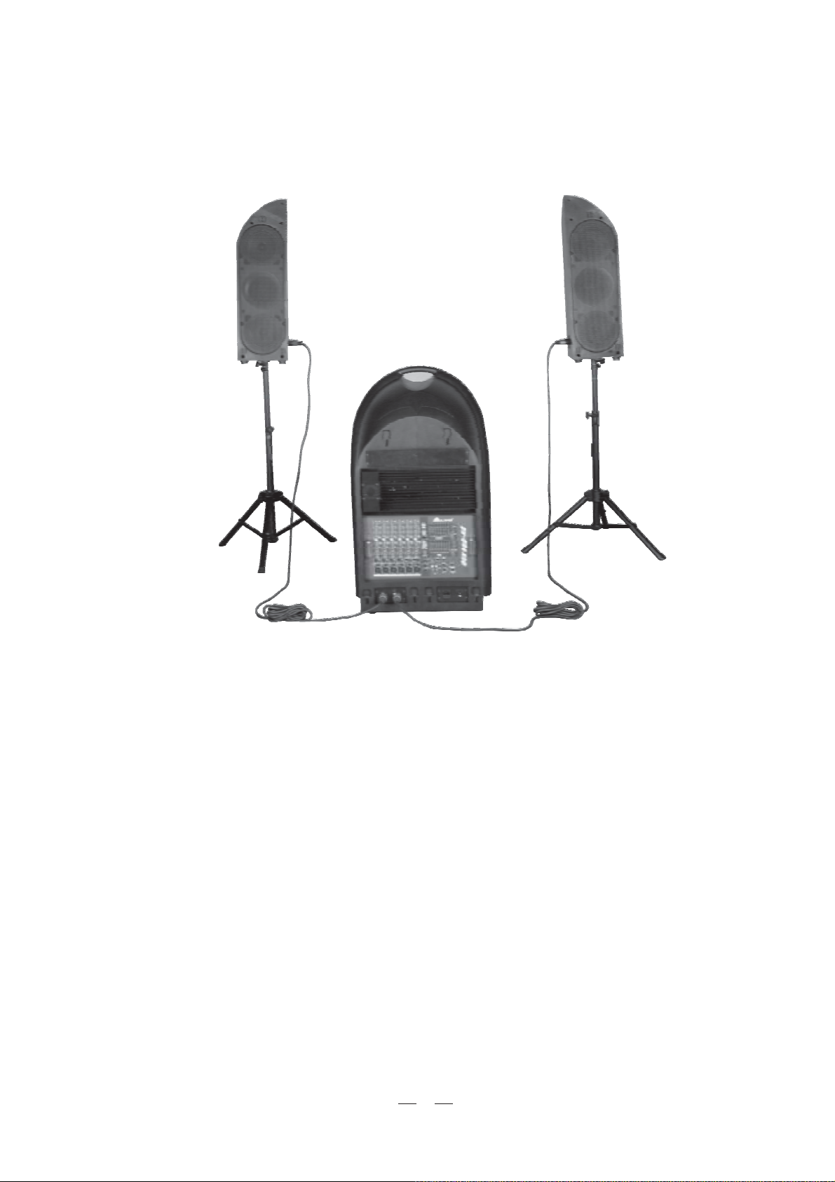
Congratulations! Now you are the owner of the OEX900 . The OEX900 is a plastic reinforced trolley that includes a
versatile mixer with DSP effects, L&R full range speaker cabinets and sub-woofer, and some essential accessories such
as power cord, signal cables, speaker cables, and speaker stands. The OEX900 adopts an optimal crossover network and
advanced power amplifier technologies, which ensures its incredible versatility and excellent audio performances.
The L&R speaker cabinets are tightly hooked on the trolley . When you operate the OEX900, take care of the setting
of the L&R cabinets first. It is the development of ALTO's experience and knowledge of speaker technology, in order
to create a system which can faithfully reproduce sound for each kind of applications.
The sub-woofer is built in trolley. It contains a 15" low speaker, which delivers a natural and powerful sound and that
will bring you unprecedented low frequency emission.
Inlaid in OEX900 panel there's compact extractable 8-channel mixer, which uses 24-bit A/D&D/A converters and 24bit DSP effects with accurate algorithms (256 presets). It also provides 6 MIC inputs with ultra low noise microphone
pre-amplifiers and+48V PHANTOM power at as well as warm, natural 3-band EQ; AUX send/return and 2TK in/out
and so on.
In a word, it is ideally suited for live sound applications, small
venues applications, recording and other musical purposes.
In order to get the best from your OEX900, we recommend you
to thoroughly read this owner's manual before installation and
operation.
2. FEATURES
Trolley appearance
2(two-way satellites) + 1(subwoofer) + 1 (8-channel mixer super combination)
Three-way full-range speaker system with 15" subwoofer
6 XLR MIC input with ultra low noise microphone pre-amplifiers and PHANTOM power+48V
2 stereo LINE input
Warm, natural 3-band EQ for each channel
Precision level control
24-bit DSP effects with powerful algorithms (16 presets with16 variations each)
Extremely high headroom offering excellent dynamic range
Plastic reinforced cabinet (polypropylene)
High power output with (L&R speaker) / (subwoofer)150 *2 150 *2WW
Two 7 m speaker cables
Two F8 folding speaker stands
Compartment for storing F8 folding stands, speaker cables, signal cable and power cord etc.
Accessory List:
Folding speaker stands 2 F8
Power cord 1 IEC power cord
Signal cable 1 2m
Customized Speaker Cable 2 7m
3
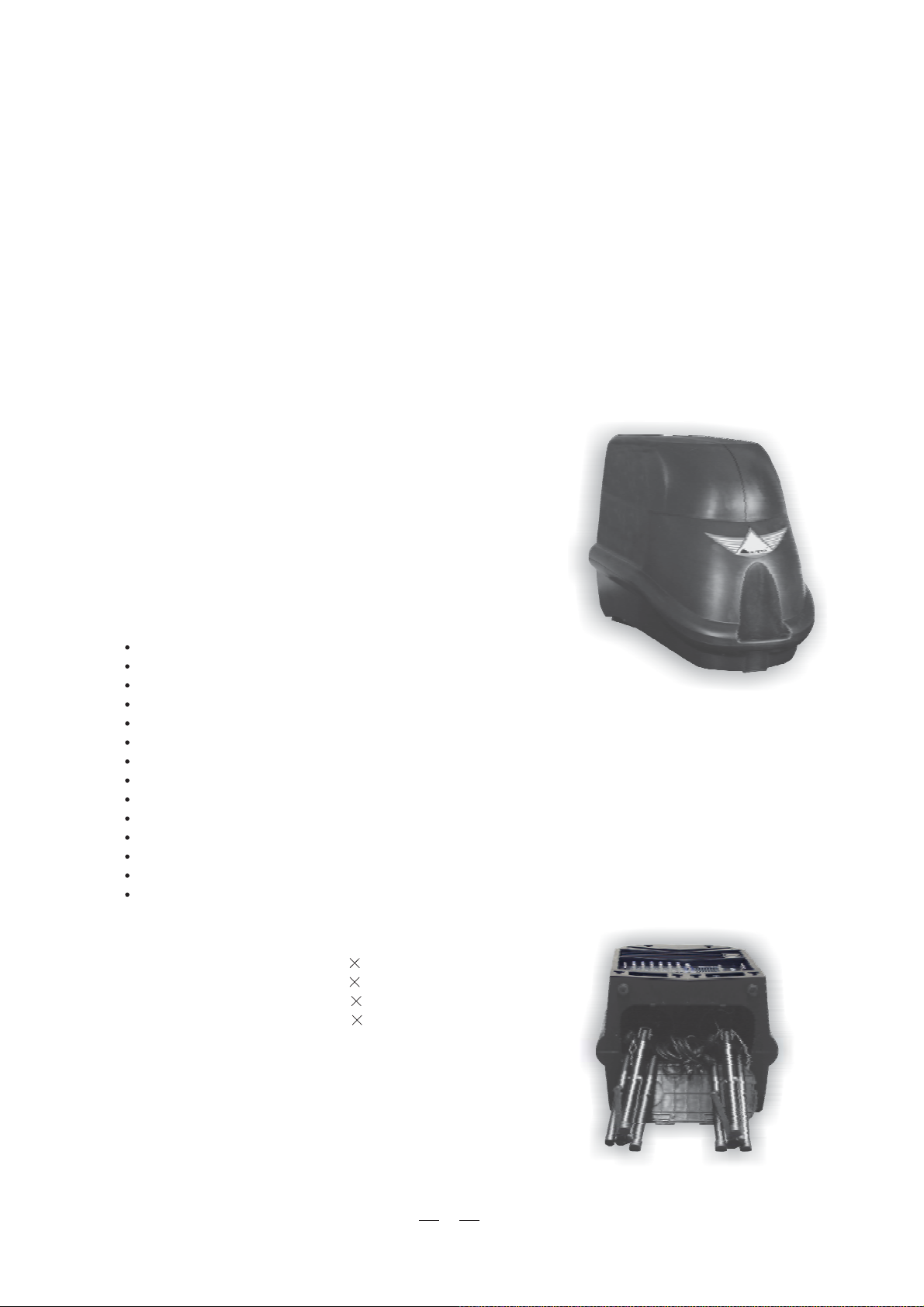
In following picture you see OEX900 most important components.
High quality L&R full range speaker cabinets
Powerful sub-woofer
Versatile multi-channel mixer
4
3. QUICK START
Though the OEX900 looks like a super formidable giant, you don't have to worry about how to carry it. As the OEX900
is equiped with two wheels, you can think of it as a trolley. Seeing is believing. Operating this unit, you will find that it is
really versatile and user-friendly. Following steps will give you a guide line to set up your OEX900.
Note: Make all initial connections with the system powered off, and, in order to avoid damaging your speakers and
excessive noise, with main mix volume control of the mixer completely turned down.
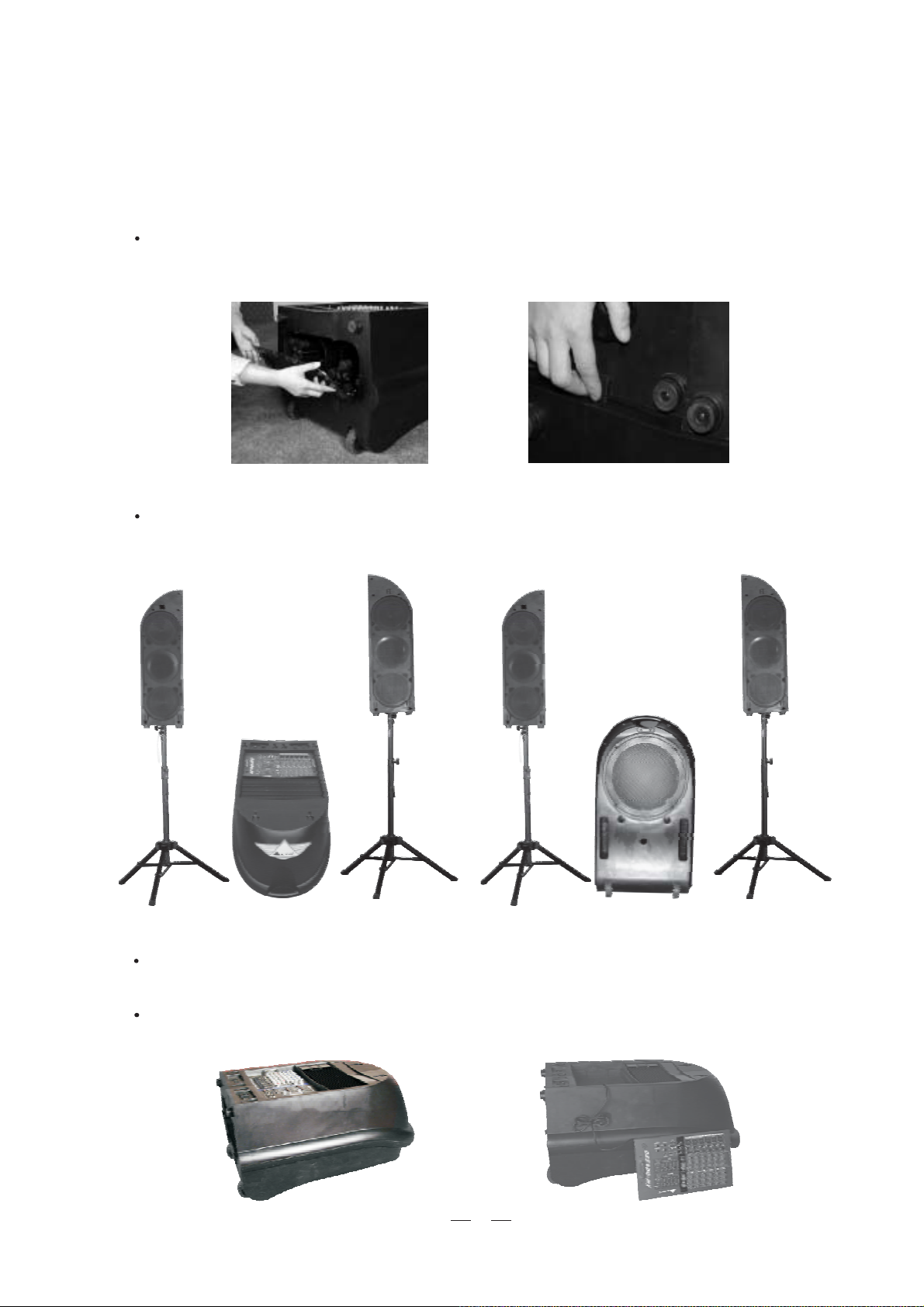
First of all extract the F8 folding speaker stands from their compartment, as shown in Fig.1. Then, as shown in
the L&R speaker cabinets from the trolley in the right direction, unsuitable operation may damageFig.2, unhook,
your equipment. In order to prevent equipment damage, please place the speaker stands on a solid, even surface.
Fig.1 Fig.2
Fix the L&R speaker cabinets on stands. as shown in Fig.3.
Note: In order to avoid feedback, please position the speakers facing the audience and far away from the
microphone.
Fig.3
Then, position the sub-woofer(trolley). Please be careful about this step, as shown in above Fig.4 proper
position will allow the sub-woofer to develop his full power and sound character.
Depending on application requirements, you can disassemble or not the mixer from the trolley. For
this application 2m. signal cable is available, as shown in following Fig.5.
Fig.5
5
Fig.4
 Loading...