


User Guide
English ( 3 – 6 )
Guía del usuario
Español ( 7 – 10 )
Guide d'utilisation
Français ( 11 – 14 )
Guida per l'uso
Italiano ( 15 – 18 )
Benutzerhandbuch
Deutsch ( 19 – 22 )
Gebruikershandleiding
Nederlands ( 23 – 26 )
Appendix
English ( 27 )
User Guide (English)
Introduction
Box Contents
TX12 |
User Guide |
Power Cable |
Safety & Warranty Manual |
Support
For the latest information about this product (system requirements, compatibility information, etc.) and product registration, visit altoprofessional.com/tx12.
For additional product support, visit altoprofessional.com/support.
Important Safety Precautions
Please note: Alto Professional and inMusic are not responsible for the use of its products or the misuse of this information for any purpose. Alto Professional and inMusic are not responsible for the misuse of its products caused by avoiding compliance with inspection and maintenance procedures. Please also refer to the included safety and warranty manual for more information.
Important: Do not suspend a TX Series loudspeaker. It is not designed for suspended applications. We recommend our Truesonic Series or Black Series loudspeakers for suspended applications instead.
Stand-Mounting
•Always install loudspeakers in accordance with applicable electrical and building codes.
•Install the loudspeaker according to its maximum weight. Check the specifications of your stand or pole to ensure it can support the loudspeaker's weight. Also, observe all safety precautions specified by the manufacturer.
•Do not mount multiple loudspeakers on the same stand or pole.
•Always verify that the stand or pole is on a flat, level, and stable surface. Also, fully extend the legs of tripod-style stands, and ensure its legs do not present a trip hazard.
•Inspect the stand (or pole and associated hardware) before each use and do not use equipment with worn, damaged, or missing parts.
•Always be cautious in windy, outdoor conditions. You may need to place additional weight (e.g., sandbags) on stand's base to improve stability. Do not attach banners or similar items to any part of a loudspeaker system. Such attachments could act as a sail and topple the system.
•Unless you are confident that you can handle the loudspeaker's weight, ask another person to help you lift it onto the stand or pole.
•Make sure your cables are out of the way of performers, production crew, and audience so they will not trip over them, pulling the loudspeaker off the stand or pole.
3
Sound Level
Permanent hearing loss may be caused by exposure to extremely high noise levels. The U.S. Occupational Safety and Health Administration (OSHA) has specified permissible exposures to certain noise levels. According to OSHA, exposure to high sound pressure levels (SPL) in excess of these limits may result in hearing loss. When using equipment capable of generating high SPL, use hearing protection while such equipment is under operation.
Hours per day |
SPL (dB) |
Example |
|
Hours per day |
SPL (dB) |
|
Example |
8 |
90 |
Small gig |
|
1.5 |
102 |
Riveting machine |
|
6 |
92 |
Train |
|
1 |
105 |
|
Machine factory |
4 |
95 |
Subway train |
|
.50 |
110 |
Airport |
|
3 |
97 |
High level desktop monitors |
|
.25 or less |
115 |
|
Rock concert |
2 |
100 |
Classical music concert |
|
|
|
|
|
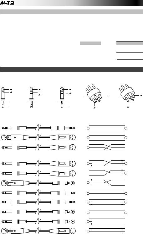
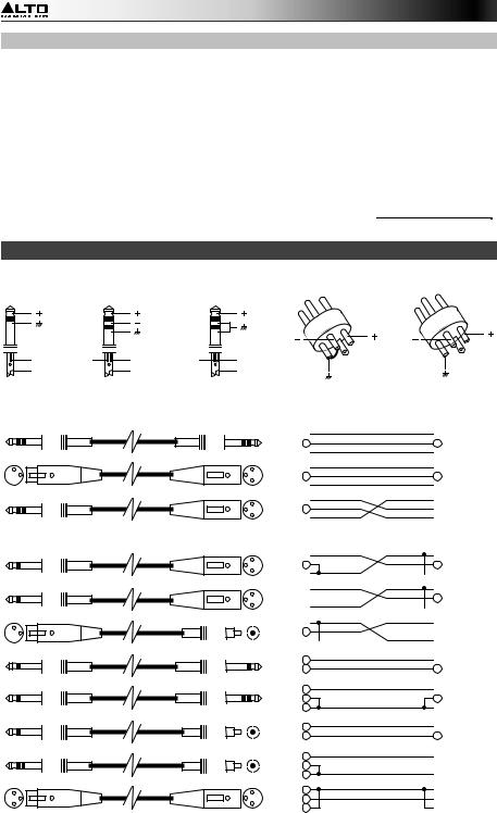
Wire Connections
You can wire your XLR or 1/4" TRS cables as balanced or unbalanced. Here are some examples:
|
|
|
|
(Pin2) |
|
(Pin2) |
|
|
|
|
(Pin3) |
(Pin3) |
|
Tip |
Ring |
Tip |
Ring |
Tip |
|
|
Sleeve |
|
Sleeve |
|
Sleeve |
|
(Pin1) |
|
|
|
|
(Pin1, linked to Pin3) |
||
|
|
|
|
|
||
Determine the wiring configuration you need for your application and audio connections:
Balanced
2 1 3
3
2 1 2 1 3 3
Tip
Ring
Sleeve
1
2
3
Tip
Ring
Sleeve
 Tip
Tip
Ring
 Sleeve
 1
1
2
 3
3
 1
1  2
2  3
3
Unbalanced
2 1 3
3
2 1 3
3
2 1 2 1 3 3
2 1 3
3
4
Tip
Ring
Sleeve
Tip
Sleeve
1
2
3
Tip
Sleeve
Tip
Ring
Sleeve
Tip
Sleeve
Tip
Ring
Sleeve
1
2
3
 1
1
2
 3
3
 1
1
2
 3
3  Center
 Screen
 Tip
Tip
Sleeve
 Tip
Tip
Ring
 Sleeve
 Center
Screen
 Center
 Screen
 1
1  2
2  3
3
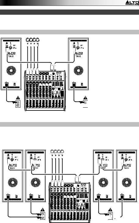
Quick Start / Connection Diagrams
Note: Items not listed in the Box Contents are sold separately.
Example A: 2 loudspeakers


 Microphones
(mixer's main outputs)
Power
Mixer
Connect each of your mixer's main outputs to the Input on a TX loudspeaker. Make sure the loudspeakers' Input Selectors are set to Line.
Power 


Example B: 2 loudspeakers, 2 extensions
Connect each of your mixer's main outputs to the Input on a TX loudspeaker. Make sure the loudspeakers' Input Selectors are set to Line. Connect each of your TX loudspeakers' Mix Outs to the inputs of your extension loudspeakers.


 Microphones
(mixer's |
main outputs) |
Power 


Power
Mixer
5
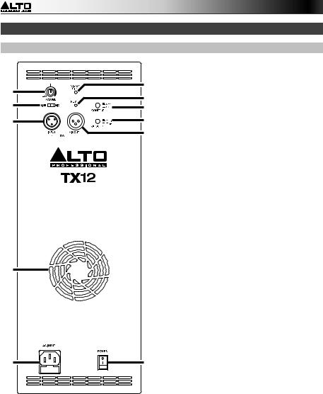
Features
Rear Panel
5
7
6
4
1
|
1. |
AC Input: Use the included power |
|
9 |
|
cable to connect this input to a power |
|
|
outlet. Make sure the Power Switch is |
||
3 |
|
set to off when connecting or |
|
|
|
||
10 |
|
disconnecting the cable. |
|
2. |
Power Switch: Use this switch to |
||
11 |
|
power the loudspeaker on or off. Make |
|
8 |
|
sure the Volume knob is set to its |
|
|
|
||
|
|
minimum |
(counterclockwise) position |
|
|
before turning it on. |
|
|
3. |
Power LED: This LED lights up when |
|
|
|
the loudspeaker is on. |
|
|
4. |
Cooling Vent: Keep the area in front of |
|
|
|
this vent clear from obstructions. The |
|
|
|
fan behind the vent cools the amplifier, |
|
|
|
preventing overheating. |
|
|
5. |
Volume: Turn this knob to adjust the |
|
|
|
loudspeaker's volume. |
|
|
6. |
Input: Use a standard XLR cable (not |
|
|
|
included) to connect your audio source |
|
|
|
to this input. Make sure to set the Input |
|
|
|
Selector to the correct position. |
|
|
7. |
Input Selector: Set this switch to the |
|
|
|
Line position when using a line-level |
|
|
|
audio source connected to the Input. |
|
|
|
Set this switch to the Mic position |
|
|
|
when using a microphone connected to |
|
|
|
the Input. |
|
|
8. |
Mix Out: Use a standard XLR cable (not |
|
2 |
|
included) to connect this output to the |
|
|
input of |
another loudspeaker (i.e., |
|
|
another TX loudspeaker). |
||
|
|
||
9.Signal Limit LED: This LED lights up when the audio signal being sent to the loudspeaker is "clipping" or distorting. If this LED illuminates frequently or steadily, reduce the volume of your audio source.
10.Contour: Engage (depress) this button to emphasize low and high frequencies by +3 dB. Disengage (raise) the switch for a flatter response for live performance or for maximum output.
11.Ground Switch: Engage (depress) this switch to reduce hum or noise.
6
Guía del usuario (Español)
Introducción
Contenido de la caja
TX12 |
Guía del usuario |
Cable de alimentación |
Manual sobre la seguridad y garantía |
Soporte
Para obtener la información más completa acerca de este product (los requisitos del sistema, compatibilidad, etc) y registro del producto, visite altoprofessional.com/tx12.
Para soporte adicional del producto, visite altoprofessional.com/support.
Precauciones importantes para la seguridad
Para tener en cuenta: Alto Professional e inMusic no son responsables del uso de sus productos o el mal uso de esta información para cualquier propósito. Alto Professional e inMusic no son responsables del mal uso de sus productos causados por la omisión del cumplimiento de los procedimientos de inspección y mantenimiento. Para más información, consulte también el manual de seguridad y garantía incluido.
Importante: No suspenda los altavoces TX Series. No se diseñaron para funcionar suspendidos. Recomendamos los altavoces Truesonic Series o Black Series para ese propósito.
Montaje en soporte
•Instale siempre los altavoces de acuerdo con los códigos de electricidad y construcción aplicables.
•Instale el altavoz de acuerdo a su peso máximo. Compruebe las especificaciones de su soporte o columna para asegurarse de que pueda soportar el peso del altavoz. Asimismo, observe todas las precauciones para la seguridad especificadas por el fabricante.
•No monte varios altavoces en el mismo soporte o columna.
•Verifique siempre que el soporte o columna esté sobre una superficie plana, nivelada y estable. Asimismo, extienda totalmente las patas de los soportes tipo trípode y asegúrese de que las patas no representen un riesgo de tropiezo.
•Inspeccione el soporte (o columna y elementos de fijación asociados) antes de cada uso y no utilice equipos con piezas desgastadas, dañadas o faltantes.
•Tenga siempre cuidado en condiciones de viento a la intemperie. Es posible que deba colocar peso adicional (como bolsas de arena) en la base del soporte para mejorar la estabilidad. No fije pancartas o elementos similares a ninguna parte del sistema de altavoces. Tales agregados pueden funcionar como velas y hacer volcar el sistema.
•Salvo que tenga confianza de que puede manejar el peso del altavoz, solicite a otra persona que le ayude a levantarlo para colocarlo en el soporte o columna.
•Asegúrese de que los cables estén fuera del camino de los intérpretes, personal de producción y audiencia, de modo que no tropiecen con ellos y hagan caer el altavoz del soporte o columna.
7
Nivel de sonido
La exposición a niveles muy altos de ruido puede causar pérdidas auditivas permanentes. La Administración de Seguridad y Salud Ocupacional de EE.UU. (OSHA) ha especificado los niveles de exposición permisibles a ciertos niveles de ruido. Según la OSHA, la exposición a niveles de presión sonora (SPL) elevados que excedan estos límites puede causar pérdidas auditivas. Cuando utilice equipos capaces de generar SPL elevados, use protecciones auditivas mientras dichos equipos están en funcionamiento.
Horas |
SPL |
|
Ejemplo |
diarias |
(dB) |
|
|
|
|
||
8 |
90 |
|
Música de bajo volumen |
6 |
92 |
|
Tren |
4 |
95 |
|
Tren subterráneo |
3 |
97 |
|
Monitores de escritorio de alto nivel |
2 |
100 |
|
Concierto de música clásica |
Horas |
SPL |
|
Ejemplo |
diarias |
(dB) |
|
|
|
|
||
1,5 |
102 |
Remachadora |
|
1 |
105 |
|
Máquina fabril |
0,50 |
110 |
|
Aeropuerto |
0,25 o menos |
115 |
Concierto de rock |
|
Cableado
Puede cablear sus cables XLR o TRS de 1/4 pulg. como balanceados o no balanceados. Aquí hay algunos ejemplos:
|
|
|
|
|
|
(Patilla 2) |
|
|
|
|
(Patilla 3) |
(Patilla 2) |
(Patilla 3) |
|
|
|
|
|
||
Punta |
Nuca |
Punta |
Nuca |
Punta |
|
|
Manguito |
|
Manguito |
|
Manguito |
(Patilla 1, unida |
(Patilla 1) |
|
|
|
|
|
a Patilla 3) |
|
|
|
|
|
|
|
Determine la configuración del cableado necesario para su aplicación y conexiones de audio:
Balanceado
2 1 3
3
2 1 2 1 3 3
Punta
Nuca
Manguito
1
2
3
Punta
Nuca
Manguito
 Punta
Punta
Nuca
 Manguito
 1
1
2
 3
3
 1
1  2
2  3
3
No balanceado
2 1 3
3
2 1 2 1 3 3
Punta
Nuca
Manguito
Punta
Manguito
1
2
3
|
|
Punta |
|
|
Manguito |
|
|
Punta |
|
|
Nuca |
|
|
Manguito |
|
|
Punta |
|
|
Manguito |
|
|
Punta |
|
|
Nuca |
|
|
Manguito |
1 |
1 |
1 |
2 |
2 |
2 |
3 |
3 |
|
|
|
3 |
8
 1
1
2
 3
3
 1
1
2
 3
3  Centro
 Anillo
 Punta
Punta
Manguito
 Punta
Punta
Nuca
 Manguito
 Centro
Anillo
 Centro
 Anillo
 1
1  2
2  3
3

Diagrama de inicio / conexión rápida
Nota: Los elementos que no se enumeran en Contenido de la caja se venden por separado.
Ejemplo A: 2 altavoces
|
Micrófonos |
|
(salidas principals |
|
del mezclador) |
Suministro |
|
eléctrico |
Mezclador |
Conecte cada una de las salidas principales de su mezclador a una entrada de un altavoz TX. Asegúrese de que los selectores de entrada de los altavoces estén en la posición Line (Línea).
Suministro eléctrico
Ejemplo B: 2 altavoces, 2 extensiones
Conecte cada una de las salidas principales de su mezclador a una entrada de un altavoz TX. Asegúrese de que los selectores de entrada de los altavoces estén en la posición Line (Línea). Conecte cada una de las salidas Mix Out (Salida de la mezcla) de sus altavoces TX a las entradas de sus altavoces de extensión.


 Micrófonos
(salidas principals |
del mezclador) |
Suministro |
|
Suministro |
|
eléctrico |
Mezclador |
||
eléctrico |
|||
|
|||
|
9 |
||
|
|
 Loading...