

Page 1
OPERATION
+ CODE MANUAL
SHIFT SELECTOR
OIL LEVEL INFORMATION, DIAGNOSTIC CODES AND PROGNOSTIC FEATURES
FOR 3000/4000 SERIES™ AND TC10™ ALLISON TRANSMISSIONS
Page 2

Table of Contents
General Information ..................................... 1
Basic Operation ......................................... 2
Section 1 - With Prognostics + With Oil Level Sensor
Fluid Levels ............................................ 3
Checking Fluid Levels..................................... 3
Prognostic Features ...................................... 4
Accessing Prognostics .................................... 5
Resetting Prognostics..................................... 6
Exit Prognostics ......................................... 6
Diagnostics Codes ....................................... 7
Section 2 - With Prognostics + Without Oil Level Sensor
Prognostic Features ...................................... 8
Accessing Prognostics .................................... 9
Resetting Prognostics.................................... 10
Exit Prognostics ........................................ 10
Diagnostics Codes ...................................... 11
Section 3 - Without Prognostics + With Oil Level Sensor
Fluid Levels ........................................... 12
Checking Fluid Levels.................................... 12
Diagnostics Codes ...................................... 14
Section 4 - Without Prognostics + Without Oil Level Sensor
Diagnostics Codes ...................................... 15
Diagnostics Transmission Codes
Codes P0122-P077F .................................... 17
Codes P0796-P0994 .................................... 18
Codes P0994-P2637 .................................... 19
Codes P2641-P281B .................................... 20
Codes P281D-U059A.................................... 21
Page 3

General Information
Control. Power. Information. The new 5th Generation Electronic Shift
Selector from Allison puts it all at your fingertips. Literally. Getting started is
easy and the selector’s complete menu of prognostic and diagnostic tools
minimize downtime and keep you on the job. Use this handy reference
booklet for step-by-step instruction on how to get the most from your shift
selector and of course, your Allison fully automatic transmission.
The Allison Advantage
Your Allison Automatic is fully electronically controlled. The Allison
electronic controls package oversees the operation of the transmission,
controlling transmission upshifts and downshifts, and providing important
information on the operation of your drive system.
Through readouts on your shift selector, you will be able to monitor
transmission oil levels, read diagnostic codes and prognostic information.
This manual will help you understand shift selector readouts and enjoy
long, trouble-free operation of your Allison Automatic.
Diagnostics
The Transmission Control Module (TCM) of your Allison Automatic
monitors the transmission’s electronic controls; and when a problem
condition is detected, it:
• May restrict shifting
• Illuminates the CHECK TRANS* light on the instrument panel
• Registers a diagnostic code
Continued illumination of the CHECK TRANS light during vehicle
operation (other than start-up) indicates that the TCM has signaled
a diagnostic code.
NOTE: Displays apply only when using a 5th Gen TCM.
* For some problems, diagnostic codes may be registered without the TCM
activating the CHECK TRANS light. Your Allison Authorized Service Network should
be consulted whenever there is a transmission-related concern. They have the
equipment to check for diagnostic codes and to correct problems.
1
Page 4
Basic Operation
5th Generation Electronic Controls Shift Selectors
As the world leader in medium- and heavy-duty commercial transmissions,
Allison Transmission continues its ongoing improvement initiative with the
introduction of 5th Generation Electronic Controls Shift Selectors.
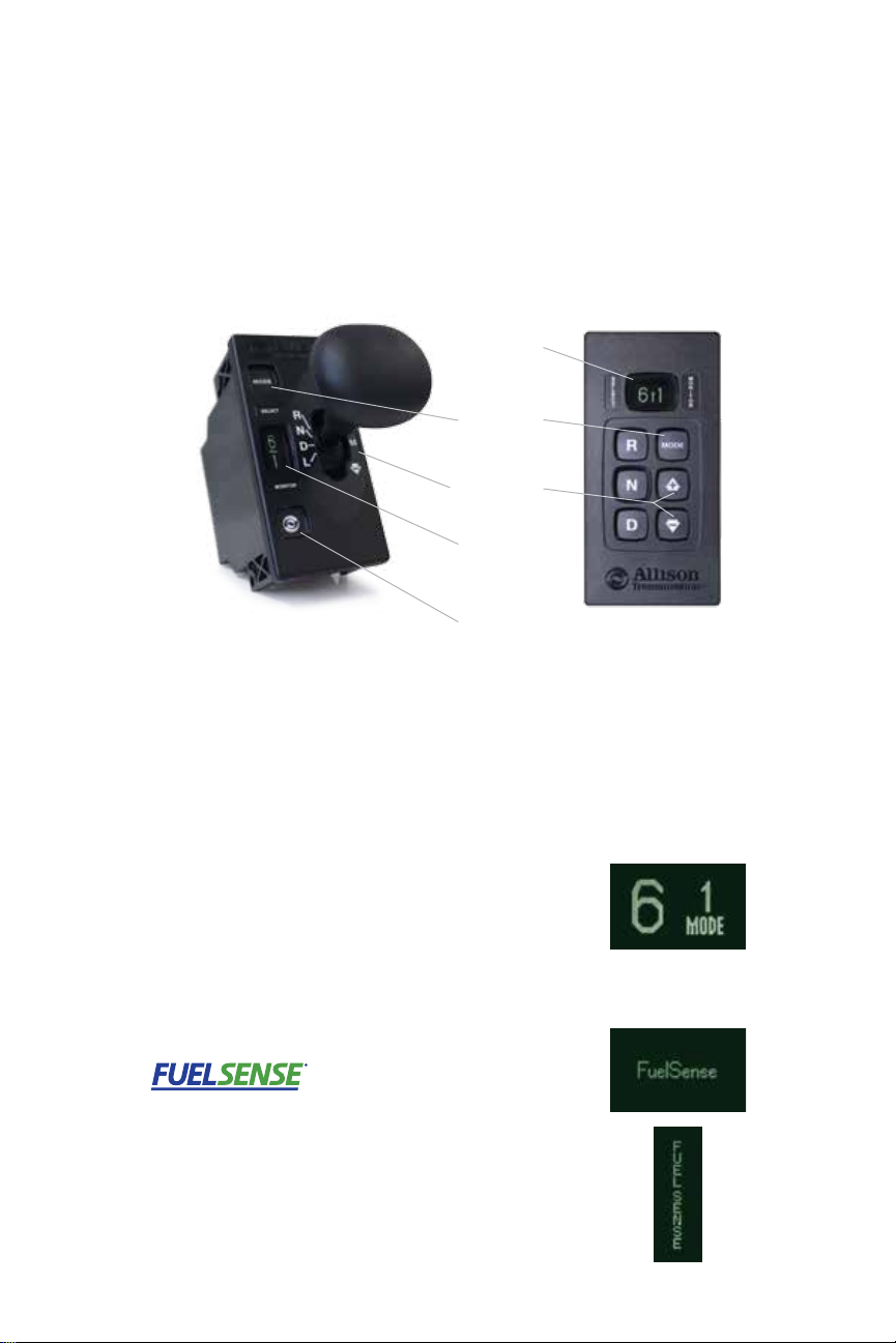
All 5th Generation Electronic Controls Shift Selectors feature easy-to-read
graphic displays that show both text and symbols.
DIGITAL
DISPLAY
MODE
BUTTON
UP/DOWN
ARROWS
DIGITAL
DISPLAY
DIAGNOSTICS
BUTTON
BUMP LEVER
PUSHBUTTON
R - REVERSE N - NEUTRAL D - DRIVE
OEMs may supply shift selectors for some vehicles equipped with 5th
Generation Electronic Controls. If your vehicle is not equipped with an
Allison-supplied shift selector, contact your OEM.
Mode Button
Allison Automatics offer primary and secondary shift
schedule modes to enhance performance or fuel
economy. The vehicle always defaults to the primary
mode [MODE is not shown on graphic display].
If equipped as such you can switch to the secondary
mode by pushing the MODE button [MODE is shown on
graphic display].
Your vehicle may be equipped with FuelSense –
Allison’s next generation in fuel-savings technology.
FuelSense is a set of unique packages of software and
electronic controls that can potentially increase fuel
economy by 20%. FuelSense icons will appear at start
up if your vehicle utilizes a FuelSense package.
2
Page 5

SECTION 1
WITH PROGNOSTICS +
WITH OIL LEVEL SENSOR
Fluid Levels
The transmission fluid cools, lubricates and transmits hydraulic power,
so it is important that the proper fluid level be maintained at all times.
If the fluid level is too low, the converter and clutches do not receive an
adequate supply of fluids. If the fluid level is too high, the fluid can aerate
causing the transmission to shift erratically or overheat.
Checking Fluid Levels
Use the following procedure to display oil level information.
To enter the oil level function:
1. Park the vehicle on a level surface, shift to N (NEUTRAL)
and apply the parking brake.
2. Using a pushbutton shift selector, simultaneously
press the UP and DOWN arrows one time.
For a bump lever shift selector, press
the DIAGNOSTICS button one time.
3. The fluid level reading will be delayed until the following
conditions are met.
• Engine must be at idle.
• Transmission is in N (NEUTRAL).
• Output speed must be zero.
• Fluid temperature must be between 104F (40C)
and 220F (104C).
• Vehicle has been stationary for two minutes to allow
the fluid to settle.
3
Page 6
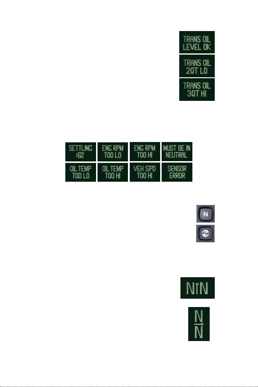
4. The shift selector displays the oil level data as follows:
• CORRECT FLUID LEVEL – The fluid is within the
correct fluid level zone when OK is shown.
• LOW FLUID LEVEL – The display shows the number
of quarts the transmission oil is low.
• HIGH FLUID LEVEL – The display shows the number
of quarts the transmission oil is overfilled.
Delayed Fluid Level Check
If the fluid level check cannot be completed, one of the following
Oil Level Display faults will be shown:
To exit the oil level function:
• For pushbutton shift selector,
press N (NEUTRAL) button.
• For bump lever shift selector, press the
DIAGNOSTICS button until you return to range display.
Prognostic Features
5th Generation Electronic Controls Shift
Selectors display prognostics in text form to
provide at-a-glance status of Oil Life, Filter Life
and Transmission Health.
The WRENCH ICON will illuminate briefly after you turn
the key to the run position on your Allison-equipped
vehicle to indicate that prognostics are enabled. If the
WRENCH ICON remains on or flashes, this indicates there
is a service issue relating to clutch, filter or fluid life.
PUSHBUTTON
BUMP LEVER
4
Page 7
Oil Life Monitor
The status of the oil life is displayed as a percentage
(OIL LIFE 100%) until fluid is due for a change.
Filter Life Monitor
The status of filter life is displayed as OIL FILTERS OK
and alerts when filters are due for a change with REPLACE FILTERS.
Transmission Health Monitor (not available for TC10)
The status of transmission health is displayed as OK or LO.
Accessing Prognostics
When you are alerted via the WRENCH ICON on the shift selector that service
is due, you can check the status by toggling through the shift selector
display as follows. Be sure to park the vehicle on a level surface, shift to
N (NEUTRAL) and apply the parking brake before accessing prognostics
through the shift selector.
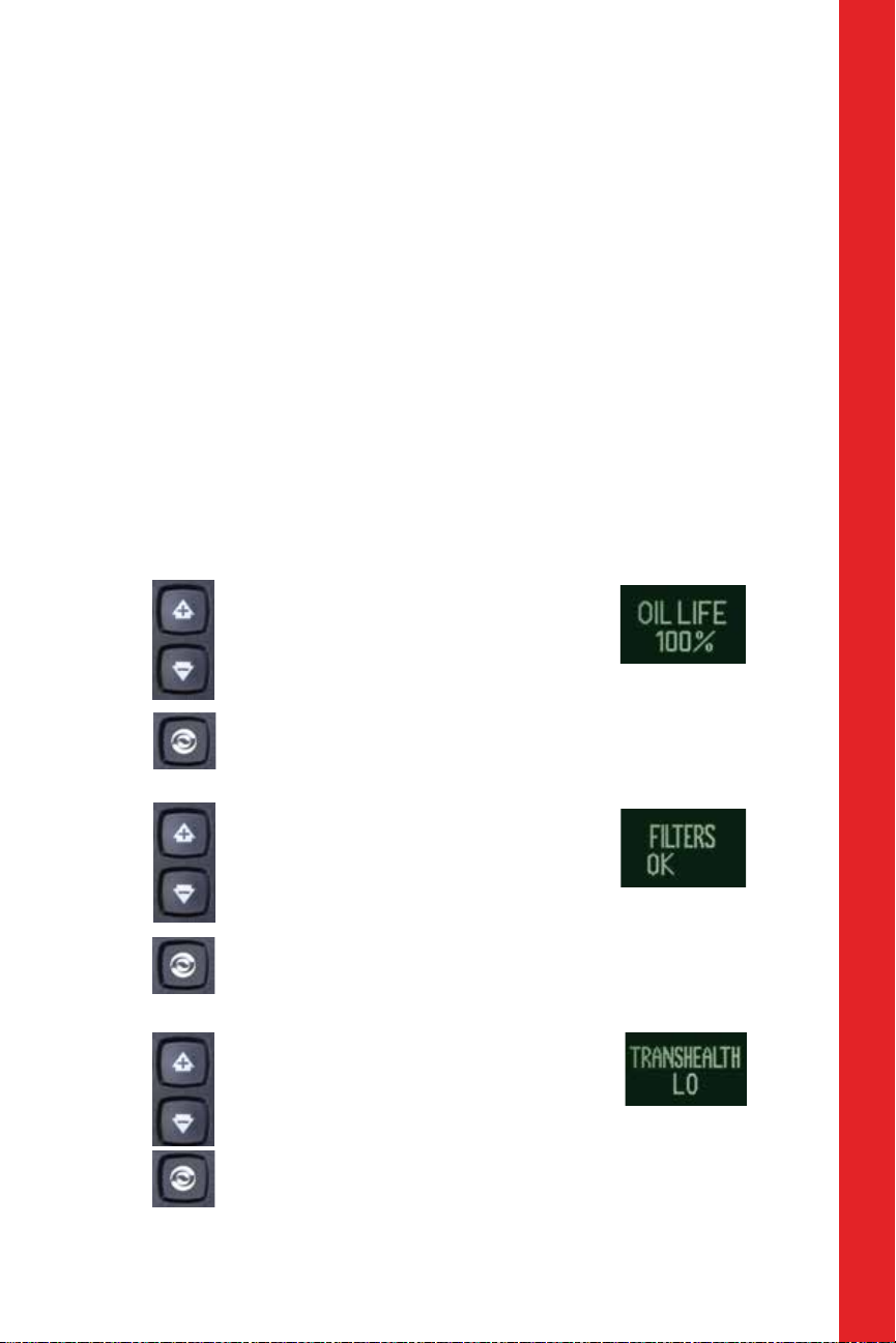
Oil Life Monitor
For a pushbutton shift selector,
simultaneously press the UP and DOWN
arrows two times.
For a bump lever shift selector,
press the DIAGNOSTICS button two times.
The percentage of the
fluid life remaining is
displayed. New fluid is
shown as OIL LIFE 100%.
WITH PROGNOSTICS + WITH OIL LEVEL SENSOR
Filter Life Monitor
For a pushbutton shift selector,
simultaneously press the UP and DOWN
arrows three times.
For a bump lever shift selector, press
the DIAGNOSTICS button three times.
Transmission Health Monitor
For a pushbutton shift selector,
simultaneously press the UP and DOWN
arrows four times.
For a bump lever shift selector, press
the DIAGNOSTICS button four times.
5
Acceptable filter life status
is shown as FILTERS OK,
unacceptable filter life status
is shown as REPLACE FILTERS.
When TRANS HEALTH OK is
shown, clutch maintenance
is not required. When TRANS
HEALTH LO is displayed, clutch
maintenance is required.
Page 8

Resetting Prognostics
Oil Life Monitor
For either a pushbutton or bump lever shift selector, press
and hold the MODE button for approximately 10 seconds
while in Oil Life Monitor mode.
Or
For either a pushbutton or bump lever shift selector,
perform the following shift sequence with the ignition
on, but the engine off. Do not stop the sequence
for more than three seconds once you have started.
N-D-N-D-N-R-N
Filter Life Monitor
For either a pushbutton or bump lever shift selector, press
and hold the MODE button for approximately 10 seconds
while in Filter Life Monitor mode.
Or
For either a pushbutton or bump lever shift selector, perform the
following shift sequence with the ignition on, but the engine off.
Do not stop the sequence for more than three seconds once you
have started.
N-R-N-R-N-D-N
Transmission Health Monitor
This must be reset manually using Allison DOC
program after correcting a clutch system issue.
Exit Prognostics
For a pushbutton shift selector, press the N (NEUTRAL)
range button.
For a bump lever shift selector, press the DIAGNOSTICS
range button until back to range display.
6
®
for PC diagnostic
Page 9

Diagnostic Codes
To enter the diagnostic code function:
1. Bring the vehicle to a complete stop.
Apply the parking brake.
2. For a pushbutton shift selector, simultaneously press
the UP and DOWN arrows five times (four times for TC10).
For a bump lever shift selector,
press the DIAGNOSTICS button five times.
3. Up to five codes may be recorded in memory.
4. Each code remains in the display until the MODE button is pushed, then
the next code is shown. Active codes are shown first, newest to oldest,
followed by any inactive codes still in the memory.
ACTIVE CODES: INACTIVE CODES:
For a detailed list of Diagnostic Transmission Codes for 5th Generation
Electronic Controls Shift Selectors, see pages 17 through 21.
WITH PROGNOSTICS + WITH OIL LEVEL SENSOR
To exit the diagnostic code function:
Any of the following methods may be used.
1. For a pushbutton shift selector, press the N (NEUTRAL)
range button.
2. For a bump lever shift selector, press the DIAGNOSTICS
range button until back to range display.
3. Wait approximately 10 minutes and the system will
automatically return to normal operating mode.
4. Turn off the vehicle engine ignition switch.
Drive the vehicle and check for code recurrence. If codes continue to
recur, bring the vehicle to an Allison Authorized Service Network to
diagnose and repair the problem causing the codes.
7
Page 10

SECTION 2
WITH PROGNOSTICS +
WITHOUT OIL LEVEL SENSOR
Prognostic Features
5th Generation Electronic Controls Shift
Selectors display prognostics in text form to
provide at-a-glance status of Oil Life, Filter Life
and Transmission Health.
The WRENCH ICON will illuminate briefly after you turn
the key to the run position on your Allison-equipped
vehicle to indicate that prognostics are enabled. If the
WRENCH ICON remains on or flashes, this indicates there
is a service issue relating to clutch, filter or fluid life.
Oil Life Monitor
The status of the oil life is displayed as a percentage
(OIL LIFE 100%) until fluid is due for a change.
PUSHBUTTON
BUMP LEVER
Filter Life Monitor
The status of filter life is displayed as OIL FILTERS OK
and alerts when filters are due for a change with REPLACE FILTERS.
Transmission Health Monitor (not available for TC10)
The status of transmission health is displayed as HIGH to LO.
8
Page 11

Accessing Prognostics
When you are alerted via the WRENCH ICON on the shift selector that service
is due, you can check the status by toggling through the shift selector
display as follows. Be sure to park the vehicle on a level surface, shift to
N (NEUTRAL)
through the shift selector.
and apply the parking brake before accessing prognostics
Oil Life Monitor
For a pushbutton shift selector,
simultaneously press the UP and DOWN
arrows one time.
For a bump lever shift selector,
press the DIAGNOSTICS button one time.
The percentage of the
fluid life remaining is
displayed. New fluid is
shown as OIL LIFE 100%.
Filter Life Monitor
For a pushbutton shift selector,
simultaneously press the UP and DOWN
arrows two times.
For a bump lever shift selector, press
the DIAGNOSTICS button two times.
Acceptable filter life status
is shown as FILTERS OK,
unacceptable filter life status
is shown as REPLACE FILTERS.
WITH PROGNOSTICS + WITHOUT OIL LEVEL SENSOR
Transmission Health Monitor
For a pushbutton shift selector,
simultaneously press the UP and DOWN
arrows three times.
For a bump lever shift selector, press
the DIAGNOSTICS button three times.
9
When TRANS HEALTH OK is
shown, clutch maintenance
is not required. When TRANS
HEALTH LO is displayed, clutch
maintenance is required.
Page 12

Resetting Prognostics
Oil Life Monitor
For either a pushbutton or bump lever shift selector, press
and hold the MODE button for approximately 10 seconds
while in Oil Life Monitor mode.
Or
For either a pushbutton or bump lever shift selector,
perform the following shift sequence with the ignition
on, but the engine off. Do not stop the sequence
for more than three seconds once you have started.
N-D-N-D-N-R-N
Filter Life Monitor
For either a pushbutton or bump lever shift selector, press
and hold the MODE button for approximately 10 seconds
while in Filter Life Monitor mode.
Or
For either a pushbutton or bump lever shift selector, perform the
following shift sequence with the ignition on, but the engine off.
Do not stop the sequence for more than three seconds once you
have started.
N-R-N-R-N-D-N
Transmission Health Monitor
This must be reset manually using Allison DOC
program after correcting a clutch system issue.
Exit Prognostics
For a pushbutton shift selector, press the N (NEUTRAL)
range button.
For a bump lever shift selector, press the DIAGNOSTICS
range button until back to range display.
10
®
for PC diagnostic
Page 13

Diagnostic Codes
To enter the diagnostic code function:
1. Bring the vehicle to a complete stop.
Apply the parking brake.
2. For a pushbutton shift selector, simultaneously
press the UP and DOWN arrows four times.
For a bump lever shift selector,
press the DIAGNOSTICS button four times.
3. Up to five codes may be recorded in memory.
4. Each code remains in the display until the MODE button is
pushed, then the next code is shown. Active codes are shown first,
newest to oldest, followed by any inactive codes still in the memory.
ACTIVE CODES: INACTIVE CODES:
For a detailed list of Diagnostic Transmission Codes for 5th Generation
Electronic Controls Shift Selectors, see pages 17 through 21.
WITH PROGNOSTICS + WITHOUT OIL LEVEL SENSOR
To exit the diagnostic code function:
Any of the following methods may be used.
1. For a pushbutton shift selector, press the N (NEUTRAL)
range button.
2. For a bump lever shift selector, press the DIAGNOSTICS
range button until back to range display.
3. Wait approximately 10 minutes and the system will
automatically return to normal operating mode.
4. Turn off the vehicle engine ignition switch.
Drive the vehicle and check for code recurrence. If codes continue to
recur, bring the vehicle to an Allison Authorized Service Network to
diagnose and repair the problem causing the codes.
11
Page 14

SECTION 3
WITHOUT PROGNOSTICS +
WITH OIL LEVEL SENSOR
Fluid Levels
The transmission fluid cools, lubricates and transmits hydraulic power,
so it is important that the proper fluid level be maintained at all times.
If the fluid level is too low, the converter and clutches do not receive an
adequate supply of fluids. If the fluid level is too high, the fluid can aerate
causing the transmission to shift erratically or overheat.
Checking Fluid Levels
Use the following procedure to display oil level information.
To enter the oil level function:
1. Park the vehicle on a level surface, shift to N (NEUTRAL)
and apply the parking brake.
2. Using a pushbutton shift selector, simultaneously
press the UP and DOWN arrows one time.
For a bump lever shift selector, press
the DIAGNOSTICS button one time.
3. The fluid level reading will be delayed until
the following conditions are met.
• Engine must be at idle.
• Transmission is in N (NEUTRAL).
• Output speed must be zero.
• Fluid temperature must be between 104F (40C)
and 220F (104C).
• Vehicle has been stationary for two minutes to allow
the fluid to settle.
12
Page 15

4. The shift selector displays the oil level data as follows:
• CORRECT FLUID LEVEL – The fluid is within the
correct fluid level zone when OK is shown.
• LOW FLUID LEVEL – The display shows the number
of quarts the transmission oil is low.
• HIGH FLUID LEVEL – The display shows the number
of quarts the transmission oil is overfilled.
Delayed Fluid Level Check
If the fluid level check cannot be completed, one of the following
Oil Level Display faults will be shown:
WITHOUT PROGNOSTICS + WITH OIL LEVEL SENSOR
To exit the oil level function:
• For pushbutton shift selector, press N (NEUTRAL)
button one time.
• For bump lever shift selector, press the
DIAGNOSTICS button until back to range display.
13
Page 16

Diagnostic Codes
To enter the diagnostic code function:
1. Bring the vehicle to a complete stop.
Apply the parking brake.
2. For a pushbutton shift selector, simultaneously
press the UP and DOWN arrows two times.
For a bump lever shift selector,
press the DIAGNOSTICS button two times.
3. Up to five codes may be recorded in memory.
4. Each code remains in the display until the MODE button is pushed, then
the next code is shown. Active codes are shown first, newest to oldest,
followed by any inactive codes still in the memory.
ACTIVE CODES: INACTIVE CODES:
For a detailed list of Diagnostic Transmission Codes for 5th Generation
Electronic Controls Shift Selectors, see pages 17 through 21.
To exit the diagnostic code function:
Any of the following methods may be used.
1. For a pushbutton shift selector, press the N (NEUTRAL)
range button.
2. For a bump lever shift selector, press the DIAGNOSTICS
range button until back to range display.
3. Wait approximately 10 minutes and the system will
automatically return to normal operating mode.
4. Turn off the vehicle engine ignition switch.
Drive the vehicle and check for code recurrence. If codes continue to
recur, bring the vehicle to an Allison Authorized Service Network to
diagnose and repair the problem causing the codes.
14
Page 17

SECTION 4
WITHOUT PROGNOSTICS +
WITHOUT OIL LEVEL SENSOR
Diagnostic Codes
To enter the diagnostic code function:
1. Bring the vehicle to a complete stop.
Apply the parking brake.
2. For a pushbutton shift selector, simultaneously
press the UP and DOWN arrows one time.
For a bump lever shift selector,
press the DIAGNOSTICS button one time.
3. Up to five codes may be recorded in memory.
4. Each code remains in the display until the MODE button is pushed, then
the next code is shown. Active codes are shown first, newest to oldest,
followed by any inactive codes still in the memory.
ACTIVE CODES: INACTIVE CODES:
For a detailed list of Diagnostic Transmission Codes for 5th Generation
Electronic Controls Shift Selectors, see pages 17 through 21.
15
Page 18

To exit the diagnostic code function:
Any of the following methods may be used.
1. For a pushbutton shift selector, press the N (NEUTRAL)
range button.
2. For a bump lever shift selector, press the DIAGNOSTICS
range button until back to range display.
3. Wait approximately 10 minutes and the system will
automatically return to normal operating mode.
4. Turn off the vehicle engine ignition switch.
Drive the vehicle and check for code recurrence. If codes continue to
recur, bring the vehicle to an Allison Authorized Service Network to
diagnose and repair the problem causing the codes.
16
Page 19

Diagnostic Transmission Codes
DIAGNOSTIC TRANSMISSION MAIN CODES P0122-P077F
DIAGNOSTIC
CODE
P0122 PEDAL POSITION SENSOR CIRCUIT LOW VOLTAGE
P0123 PEDAL POSITION SENSOR CIRCUIT HIGH VOLTAGE
P0218 TRANSMISSION FLUID OVER TEMPERATURE CONDITION
P0562 SYSTEM VOLTAGE LOW
P057C BRAKE PEDAL POSITION SENSOR LOW
P057D BRAKE PEDAL POSITION SENSOR HIGH
P0602 TCM NOT PROGRAMMED
P0603 INTERNAL CONTROL MODULE KEEP ALIVE MEMORY ERROR
P0604 CONTROL MODULE RANDOM ACCESS MEMORY (RAM)
P0607 CONTROL MODULE PERFORMANCE
P060C MAIN PROCESSOR MONITOR FAULT
P0614 TORQUE CONTROL DATA MISMATCH - ECM/TCM
P0634 TCM INTERNAL TEMPERATURE TOO HIGH
P0642 SENSOR REFERENCE VOLTAGE “A” CIRCUIT FAULT
P0652 SENSOR REFERENCE VOLTAGE “B” CIRCUIT FAULT
P0657 ACTUATOR SUPPLY CIRCUIT VOLTAGE 1 OPEN (HSD 1)
P0658 ACTUATOR SUPPLY CIRCUIT VOLTAGE 1 LOW (HSD 1)
P0659 ACTUATOR SUPPLY CIRCUIT VOLTAGE 1 HIGH (HSD 1)
P0701 TRANSMISSION CONTROL SYSTEM PERFORMANCE
P0703 BRAKE SWITCH CIRCUIT
P0708 TRANSMISSION RANGE SENSOR CIRCUIT HIGH
P070C TRANSMISSION FLUID LEVEL SENSOR CIRCUIT LOW
P070D TRANSMISSION FLUID LEVEL SENSOR CIRCUIT HIGH
P0712 TRANSMISSION FLUID TEMPERATURE SENSOR CIRCUIT LOW
P0713 TRANSMISSION FLUID TEMPERATURE SENSOR CIRCUIT HIGH
P0715 TURBINE SHAFT SPEED SENSOR CIRCUIT
P0716 TURBINE SHAFT SPEED SENSOR CIRCUIT PERFORMANCE
P0717 TURBINE SHAFT SPEED SENSOR CIRCUIT NO SIGNAL
P071A NEUTRAL AT STOP INPUT FAILED ON
P071D GENERAL PURPOSE INPUT FAULT
P0720 OUTPUT SHAFT SPEED SENSOR CIRCUIT
P0721 OUTPUT SHAFT SPEED SENSOR CIRCUIT PERFORMANCE
P0722 OUTPUT SHAFT SPEED SENSOR CIRCUIT NO SIGNAL
P0725 ENGINE SPEED SENSOR CIRCUIT
P0726 ENGINE SPEED SENSOR CIRCUIT PERFORMANCE
P0727 ENGINE SPEED SENSOR CIRCUIT NO SIGNAL
P0729 INCORRECT 6TH GEAR RATIO
P0731 INCORRECT 1ST GEAR RATIO
P0732 INCORRECT 2ND GEAR RATIO
P0733 INCORRECT 3RD GEAR RATIO
P0734 INCORRECT 4TH GEAR RATIO
P0735 INCORRECT 5TH GEAR RATIO
P0736 INCORRECT REVERSE RATIO
P0 741 TORQUE CONVERTER CLUTCH (TCC) SYSTEM STUCK OFF
P0752 SHIFT SOLENOID 1 VALVE PERFORMANCE - STUCK ON
P076F INCORRECT 7TH GEAR RATIO
P0776 PRESSURE CONTROL SOLENOID (PCS) 2 STUCK OFF
P0777 PRESSURE CONTROL SOLENOID (PCS) 2 STUCK ON
P077F INCORRECT REVERSE 2 RATIO
CODE
DESCRIPTION
17
Page 20

DIAGNOSTIC
CODE
P0796 PRESSURE CONTROL SOLENOID (PCS) 3 STUCK OFF
P0797 PRESSURE CONTROL SOLENOID (PCS) 3 STUCK ON
P07D9 INCORRECT 8TH GEAR RATIO
P07F6 INCORRECT 9TH GEAR RATIO
P07F7 INCORRECT 10TH GEAR RATIO
P081B CRANK ENABLE CIRCUIT HIGH
P0837 FOUR WHEEL DRIVE (4WD) SWITCH CIRCUIT RANGE/PERFORMANCE
P083C TRANSMISSION FLUID PRESSURE SWITCH 6 CIRCUIT LOW
P083C TRANSMISSION FLUID PRESSURE SWITCH 6 CIRCUIT LOW
P083D TRANSMISSION FLUID PRESSURE SWITCH 6 CIRCUIT HIGH
P083D TRANSMISSION FLUID PRESSURE SWITCH 6 CIRCUIT HIGH
P0842 TRANSMISSION FLUID PRESSURE SWITCH 1 CIRCUIT LOW
P0843 TRANSMISSION FLUID PRESSURE SWITCH 1 CIRCUIT HIGH
P0847 TRANSMISSION FLUID PRESSURE SWITCH 2 CIRCUIT LOW
P0848 TRANSMISSION FLUID PRESSURE SWITCH 2 CIRCUIT HIGH
P084C TRANSMISSION FLUID PRESSURE SWITCH TCC CIRCUIT LOW
P084D TRANSMISSION FLUID PRESSURE SWITCH TCC CIRCUIT HIGH
P0872 TRANSMISSION FLUID PRESSURE SWITCH 3 CIRCUIT LOW
P0873 TRANSMISSION FLUID PRESSURE SWITCH 3 CIRCUIT HIGH
P0877 TRANSMISSION FLUID PRESSURE SWITCH 4 CIRCUIT LOW
DIAGNOSTIC TRANSMISSION MAIN CODES P0796-P0994
P0878 TRANSMISSION FLUID PRESSURE SWITCH 4 CIRCUIT HIGH
P0880 TCM POWER INPUT SIGNAL
P0881 TCM POWER INPUT SIGNAL PERFORMANCE
P0882 TCM POWER INPUT SIGNAL LOW
P0883 TCM POWER INPUT SIGNAL HIGH
P088A TRANSMISSION FILTER MAINTENANCE ALERT
P088B TRANSMISSION FILTER MAINTENANCE REQUIRED
P0894 UNEXPECTED MECHANICAL GEAR DISENGAGEMENT
P0897 TRANSMISSION FLUID DETERIORATED
P0960 MAIN PRESSURE MODULATION SOLENOID CONTROL CIRCUIT OPEN
P0961 MAIN PRESSURE MODULATION SOLENOID SYSTEM PERFORMANCE
P0962 MAIN PRESSURE MODULATION SOLENOID CONTROL CIRCUIT LOW
P0963 MAIN PRESSURE MODULATION SOLENOID CONTROL CIRCUIT HIGH
P0964 PRESSURE CONTROL SOLENOID (PCS) 2 CONTROL CIRCUIT OPEN
P0966 PRESSURE CONTROL SOLENOID (PCS) 2 CONTROL CIRCUIT LOW
P0967 PRESSURE CONTROL SOLENOID (PCS) 2 CONTROL CIRCUIT HIGH
P0968 PRESSURE CONTROL SOLENOID (PCS) 3 CONTROL CIRCUIT OPEN
P0970 PRESSURE CONTROL SOLENOID (PCS) 3 CONTROL CIRCUIT LOW
P0971 PRESSURE CONTROL SOLENOID (PCS) 3 CONTROL CIRCUIT HIGH
P0973 SHIFT SOLENOID 1 CONTROL CIRCUIT LOW
P0974 SHIFT SOLENOID 1 CONTROL CIRCUIT HIGH
P0976 SHIFT SOLENOID 2 CONTROL CIRCUIT LOW
P0977 SHIFT SOLENOID 2 CONTROL CIRCUIT HIGH
P0979 SHIFT SOLENOID 3 CONTROL CIRCUIT LOW
P097A SHIFT SOLENOID 1 CONTROL CIRCUIT OPEN
P097B SHIFT SOLENOID 2 CONTROL CIRCUIT OPEN
P097C SHIFT SOLENOID 3 CONTROL CIRCUIT OPEN
P0980 SHIFT SOLENOID 3 CONTROL CIRCUIT HIGH
P0989 RETARDER PRESSURE SENSOR CIRCUIT LOW
P0990 RETARDER PRESSURE SENSOR CIRCUIT HIGH
P0994 TRANSMISSION FLUID PRESSURE SWITCH 5 CIRCUIT LOW
CODE
DESCRIPTION
18
Page 21

DIAGNOSTIC
CODE
P0994 TRANSMISSION FLUID PRESSURE SWITCH 5 CIRCUIT LOW
P0995 TRANSMISSION FLUID PRESSURE SWITCH 5 CIRCUIT HIGH
P0995 TRANSMISSION FLUID PRESSURE SWITCH 5 CIRCUIT HIGH
P0A0B HIGH VOLTAGE INTERLOCK LOOP 1 INVALID
P0A2F DRIVE MOTOR OVER TEMPERATURE
P0A44 DRIVE MOTOR OVERSPEED
P0A7D ENERGY STORAGE SYSTEM OVER DISCHARGE
P0A90 DRIVE MOTOR INVALID DIRECTION
P0AA6 ISOLATION STATUS INVALID
P0B37 SERVICE DISCONNECT INVALID
P0C19 DRIVE MOTOR TORQUE DELIVERED PERFORMANCE
P0C26 ELECTRIC PUMP POWER DRAW TOO HIGH
P0C2C ELECTRIC PUMP SPEED INCORRECT
P0C30 ENERGY STORAGE SYSTEM OVER CHARGE
P0C76 HIGH VOLTAGE BUS DISCHARGE TIME TOO LONG
P0DA8 HYBRID BATTERY VOLTAGE/DRIVE MOTOR INVERTER VOLTAGE
P1739 INCORRECT LOW GEAR RATIO
P1790 GEAR SHIFT MODULE 1 CALIBRATION INVALID
P1791 GEAR SHIFT MODULE 2 CALIBRATION INVALID
P1891 THROTTLE POSITION SENSOR PWM SIGNAL LOW
P1892 THROTTLE POSITION SENSOR PWM SIGNAL HIGH
P1901 COUNTERSHAFT SPEED SENSOR CIRCUIT
P1902 COUNTERSHAFT SPEED SENSOR PERFORMANCE
P1903 COUNTERSHAFT SPEED SENSOR NO ACTIVITY
P1907 SHIFT FORK STUCK MOVING TO REVERSE POSITION
P1922 TRANSMISSION FLUID PRESSURE SWITCH A CIRCUIT LOW
P1923 TRANSMISSION FLUID PRESSURE SWITCH A CIRCUIT HIGH
P1927 TRANSMISSION FLUID PRESSURE SWITCH B CIRCUIT LOW
P1928 TRANSMISSION FLUID PRESSURE SWITCH B CIRCUIT HIGH
P192C TRANSMISSION FLUID PRESSURE SWITCH C CIRCUIT LOW
P192D TRANSMISSION FLUID PRESSURE SWITCH C CIRCUIT HIGH
P1A01 TRANSMISSION CONTROL SYSTEM 2 PERFORMANCE
P1A0C TRANSMISSION FLUID LEVEL SENSOR 2 CIRCUIT LOW
P1A0D TRANSMISSION FLUID LEVEL SENSOR 2 CIRCUIT HIGH
P1A11 DC/DC CONVERTER “A” FAULT ACTIVE
P1A12 DC/DC CONVERTER “B” FAULT ACTIVE
P1A13 ELECTRIC PUMP FAULT ACTIVE
P1A14 ENERGY STORAGE SYSTEM FAULT ACTIVE
P1A15 INVERTER FAULT ACTIVE
P1A20 HIGH VOLTAGE INTERLOCK LOOP 2 INVALID
P1A30 INVERTER OPERATING MODE NOT CORRELATED
P1A31 ENERGY STORAGE SYSTEM OPERATING MODE NOT CORRELATED
P1A32 DC/DC CONVERTER “A” OPERATING MODE NOT CORRELATED
P1A33 DC/DC CONVERTER “B” OPERATING MODE NOT CORRELATED
P1A34 ELECTRIC PUMP OPERATING MODE NOT CORRELATED
P1A3F INVERTER ISOLATION FAULT
P1A40 HIGH VOLTAGE BUS POWER BALANCE
P2184 ENGINE COOLANT TEMPERATURE SENSOR 2 CIRCUIT LOW
P2185 ENGINE COOLANT TEMPERATURE SENSOR 2 CIRCUIT HIGH
P2637 TORQUE MANAGEMENT FEEDBACK SIGNAL A
CODE
DESCRIPTION
CORRELATION
DIAGNOSTIC TRANSMISSION MAIN CODES P0994-P2637
19
Page 22

DIAGNOSTIC TRANSMISSION MAIN CODES P2641-P281B
DIAGNOSTIC
CODE
P2641 TORQUE MANAGEMENT FEEDBACK SIGNAL B
P2669 ACTUATOR SUPPLY CIRCUIT VOLTAGE 2 OPEN (HSD 2)
P2670 ACTUATOR SUPPLY CIRCUIT VOLTAGE 2 LOW (HSD 2)
P2671 ACTUATOR SUPPLY CIRCUIT VOLTAGE 2 HIGH (HSD 2)
P2684 ACTUATOR SUPPLY CIRCUIT VOLTAGE 3 OPEN (HSD 3)
P2685 ACTUATOR SUPPLY CIRCUIT VOLTAGE 3 LOW (HSD 3)
P2686 ACTUATOR SUPPLY CIRCUIT VOLTAGE 3 HIGH (HSD 3)
P26E7 ACTUATOR SUPPLY CIRCUIT VOLTAGE 4 OPEN (HSD 4)
P26E8 ACTUATOR SUPPLY CIRCUIT VOLTAGE 4 LOW (HSD 4)
P26E9 ACTUATOR SUPPLY CIRCUIT VOLTAGE 4 HIGH (HSD 4)
P2714 PRESSURE CONTROL SOLENOID (PCS) 4 STUCK OFF
P2715 PRESSURE CONTROL SOLENOID (PCS) 4 STUCK ON
P2718 PRESSURE CONTROL SOLENOID (PCS) 4 CONTROL CIRCUIT OPEN
P2720 PRESSURE CONTROL SOLENOID (PCS) 4 CONTROL CIRCUIT LOW
P2721 PRESSURE CONTROL SOLENOID (PCS) 4 CONTROL CIRCUIT HIGH
P2723 PRESSURE CONTROL SOLENOID (PCS) 1 STUCK OFF
P27 24 PRESSURE CONTROL SOLENOID (PCS) 1 STUCK ON
P2727 PRESSURE CONTROL SOLENOID (PCS) 1 CONTROL CIRCUIT OPEN
P2729 PRESSURE CONTROL SOLENOID (PCS) 1 CONTROL CIRCUIT LOW
P2730 PRESSURE CONTROL SOLENOID (PCS) 1 CONTROL CIRCUIT HIGH
P2732 PRESSURE CONTROL SOLENOID (PCS) 5 STUCK OFF
P2733 PRESSURE CONTROL SOLENOID (PCS) 5 STUCK ON
P2736 PRESSURE CONTROL SOLENOID (PCS) 5 CONTROL CIRCUIT OPEN
P2738 PRESSURE CONTROL SOLENOID (PCS) 5 CONTROL CIRCUIT LOW
P2739 PRESSURE CONTROL SOLENOID (PCS) 5 CONTROL CIRCUIT HIGH
P273F RETARDER OIL TEMPERATURE SENSOR OVER TEMPERATURE CONDITION
P2742 RETARDER OIL TEMPERATURE SENSOR CIRCUIT LOW
P2743 RETARDER OIL TEMPERATURE SENSOR CIRCUIT HIGH
P274B TRANSMISSION FLUID TEMPERATURE SENSOR “C” CIRCUIT
P274C TRANSMISSION FLUID TEMPERATURE SENSOR “C” CIRCUIT LOW
P274D TRANSMISSION FLUID TEMPERATURE SENSOR “C” CIRCUIT HIGH
P274F TRANSMISSION FLUID SENSOR “C” OVER TEMPERATURE
P2761 TORQUE CONVERTER CLUTCH (TCC) PRESSURE CONTROL
P2763 TORQUE CONVERTER CLUTCH (TCC) PRESSURE CONTROL
P2764 TORQUE CONVERTER CLUTCH (TCC) PRESSURE CONTROL
P2789 TRANSMISSION CLUTCH LIFE EXPIRED (CLUTCH ADAPTIVE
P2793 GEAR SHIFT DIRECTION CIRCUIT
P2808 PRESSURE CONTROL SOLENOID (PCS) 6 STUCK OFF
P2809 PRESSURE CONTROL SOLENOID (PCS) 6 STUCK ON
P2812 PRESSURE CONTROL SOLENOID (PCS) 6 CONTROL CIRCUIT OPEN
P2814 PRESSURE CONTROL SOLENOID (PCS) 6 CONTROL CIRCUIT LOW
P2815 PRESSURE CONTROL SOLENOID (PCS) 6 CONTROL CIRCUIT HIGH
P2817 PRESSURE CONTROL SOLENOID (PCS) 7 STUCK OFF
P2818 PRESSURE CONTROL SOLENOID (PCS) 7 STUCK ON
P281B PRESSURE CONTROL SOLENOID (PCS) 7 CONTROL CIRCUIT OPEN
CODE
DESCRIPTION
RANGE/PERFORMANCE
CONDITION
SOLENOID (PCS) CONTROL CIRCUIT/OPEN
SOLENOID (PCS) CONTROL CIRCUIT HIGH
SOLENOID (PCS) CONTROL CIRCUIT LOW
LEARNING AT LIMIT)
20
Page 23

DIAGNOSTIC
CODE
P281D PRESSURE CONTROL SOLENOID (PCS) 7 CONTROL CIRCUIT LOW
P281E PRESSURE CONTROL SOLENOID (PCS) 7 CONTROL CIRCUIT HIGH
P2824 PRESSURE CONTROL SOLENOID (PCS) 8 CONTROL CIRCUIT OPEN
P2826 PRESSURE CONTROL SOLENOID (PCS) 8 CONTROL CIRCUIT LOW
P2827 PRESSURE CONTROL SOLENOID (PCS) 8 CONTROL CIRCUIT HIGH
P2832 SHIFT FORK POSITION CIRCUIT PERFORMANCE
P2833 SHIFT FORK POSITION CIRCUIT LOW
P2834 SHIFT FORK POSITION CIRCUIT HIGH
P2849 SHIFT FORK STUCK MOVING TO FORWARD POSITION
P284D SHIFT FORK UNREQUESTED MOVEMENT
P2879 ENGINE/HYBRID CLUTCH SYSTEM SLIPPING
P287A ENGINE CLUTCH STUCK ON
C1312 RETARDER REQUEST SENSOR CIRCUIT LOW
C1313 RETARDER REQUEST SENSOR CIRCUIT HIGH
U0073 CAN COMMUNICATION BUS 1 OFF
U0074 CAN COMMUNICATION BUS 2 OFF
U0100 LOST COMMUNICATIONS WITH ECM A
U0103 LOST COMMUNICATION WITH GEAR SHIFT MODULE 1
U0110 LOST COMMUNICATION WITH DRIVE MOTOR CONTROL MODULE
U0111 LOST COMMUNICATION WITH ENERGY STORAGE SYSTEM
U0287 LOST COMMUNICATION WITH ELECTRIC PUMP
U0291 LOST COMMUNICATION WITH GEAR SHIFT MODULE 2
U0298 LOST COMMUNICATION WITH DC/DC CONVERTER “A”
U0299 LOST COMMUNICATION WITH DC/DC CONVERTER “B”
U0304 GEAR SHIFT MODULE 1 INCOMPATIBLE
U0333 GEAR SHIFT MODULE 2 INCOMPATIBLE
U0404 GEAR SHIFT MODULE 1 INVALID DATA
U0411 INVERTER INVALID DATA
U0412 ENERGY STORAGE SYSTEM INVALID DATA
U0588 ELECTRIC PUMP INVALID DATA
U0592 GEAR SHIFT MODULE 2 INVALID DATA
U0599 DC/DC CONVERTER “A” INVALID DATA
U059A DC/DC CONVERTER “B” INVALID DATA
CODE
DESCRIPTION
CONTROL MODULE
DIAGNOSTIC TRANSMISSION MAIN CODES P281D-U059A
21
Page 24

Information contained in this brochure is designed to give you
an overview of the Oil Level Sensor, Diagnostics and Prognostic
Features on your Allison Automatic and is not intended to replace
your Operator’s Manual.
To order an Operator’s Manual, go to allisontransmission.com or
call toll free 888-666-5799.
One Allison Way
Indianapolis, Indiana, USA 46222-3271
Information or specifications subject to
change without notice or obligation.
allisontransmission.com
SA7497EN (2014/10)
ISO/QS 9000 and ISO 14001 Certified
© 2014 Allison Transmission Inc.
All rights reserved.
 Loading...