

Page 1

Troubleshooting Manual
5000, 6000, 8000, 9000 Series
Off-Highway Transmissions
Commercial Electronic Controls 2 (CEC2)
TS3353EN
Page 2
Troubleshooting
Manual
Allison Off-Highway
5000, 6000, 8000, 9000 Series Transmissions
TS3353EN
Commercial Electronic Controls 2 (CEC 2)
M 5610A, M 5610AR
S 5610H, S 5610NR, S 5610M
M 6610A, M 6610AR
S 6610H, S 6610HR, S 6610M
M 8610A, M 8610AR
S 8610H, S 8610HR, S 8610M, S 8610MR
M 9610A, M 9610AR
S 9610A, S 9610AR, S 9610M, S 9610MR
S 9810A, S 9810AR, S 9810H, S 9810HR, S 9810M, S 9810MR
2000 SEPTEMBER
Division of General Motors Corporation
P.O. Box 894 Indianapolis, Indiana 46206-0894
www.allisontransmission.com
Printed in the U.S.A. Copyright © 2000 General Motors Corp.
Page 3

COMMERCIAL ELECTRONIC CONTROLS 2 (CEC 2) TROUBLESHOOTING MANUAL
FOREWORD — How to Use This Manual
This manual provides troubleshooting information for Allison Transmission Division, 5000, 6000, 8000, and
9000 Series Off-Highway Transmissions which have CEC 2. Service Manuals SM1866EN (5000, 6000),
SM1228EN (8000) and SM1833EN (9000), plus Parts Catalogs PC1860EN (5000, 6000), PC1249EN (8000) and
PC1830EN (9000) may be used in conjunction with this manual.
This manual includes:
•
Description of the CEC 2 system.
•
Description of the electronic control system components.
Description of diagnostic codes, system responses to faults, and troubleshooting.
•
•
Wire, terminal, and connector repair information.
Specific instructions for using many of the available or required service tools and equipment are not included in
this manual. The service tool manufacturer will furnish instructions for using the tools or equipment.
Additional information may be published from time to time in Service Information Letters (SIL) and will be
included in future revisions of this and other manuals. Please use these SILs to obtain up-to-date information
concerning Allison Transmission products.
This publication is revised periodically to include improvements, new models, special tools, and procedures. A
revision is indicated by a letter suffix added to the publication number. Check with your Allison Transmission
service outlet for the currently applicable publication. Additional copies of this publication may be purchased from
authorized Allison Transmission service outlets or from:
SGI, Inc.
Attn: Allison Literature Fulfillment Desk
8350 Allison A venue
Indianapolis, IN 46268
TOLL FREE: 888-666-5799
INTERNATIONAL: 317-471-4995
Take time to revie w the Table of Contents and the manual. Reviewing the Table of Contents will aid you in quickly
locating information.
NOTE: Allison Transmission is providing for service of wiring harnesses and wiring harness components as
follows:
•
Repair parts for the internal wiring harness and for wiring harness components attached to the
shift selector will be available through the Allison Transmission Parts Distribution Center (PDC).
Use the P/N from your appropriate parts catalog or from Appendix E in this manual. Allison
Transmission is responsible for warranty on these parts.
•
Repair parts for the external harnesses and external harness components must be obtained from
St. Clair Technologies Inc. (SCTI). SCTI provides parts to any Allison customer or OEM and is
responsible for warranty on these parts. SCTI recognizes ATD, manufacturers, and SCTI part
numbers. SCTI provides a technical HELPLINE at 519-627-1673 (Wallaceburg). SCTI will have
parts catalogs available. The SCTI addresses and phone numbers for parts outlets are:
St. Clair Technologies, Inc.
1050 Old Glass Road
Wallaceburg, Ontario, N8A 3T2
Phone: (519) 627-1673
Fax: (519) 627-4227
St. Clair Technologies, Inc.
1111 Mikesell Street
Charlotte, MI 48813
Phone: (517) 541-8166
Fax: (517) 541-8167
St. Clair Technologies, Inc.
c/o Mequilas Tetakawi
Carr. Internationale KM 1969
Guadalajara – Nogales, KM2
Empalme, Sonora, Mexico
Phone: 011-52-622-34661
Fax: 011-52-622-34662
•
St. Clair Technologies, Inc. stocks a CEC 2 external harness repair kit, P/N 29532362, as a source
for some external harness repair parts. SCTI is the source for external harness repair parts.
ii Copyright © 2000 General Motors Corp.
Page 4

COMMERCIAL ELECTRONIC CONTROLS 2 (CEC 2) TROUBLESHOOTING MANUAL
IMPORTANT SAFETY NOTICE
IT IS YOUR RESPONSIBILITY to be completely familiar with the warnings and cautions
used in this manual. These warnings and cautions advise against using specific service
procedures that can result in personal injury, equipment damage, or cause the equipment to
become unsafe. These warnings and cautions are not exhaustive. Allison Transmission could
not possibly know, evaluate, or advise the service trade of all conceivable procedures by which
service might be performed or of the possible hazardous consequences of each procedure.
Consequently, Allison Transmission has not undertaken any such broad evaluation.
Accordingly, ANYONE WHO USES A SERVICE PROCEDURE OR TOOL WHICH IS NOT
RECOMMENDED BY ALLISON TRANSMISSION MUST first be thoroughly satisfied
that neither personal safety nor equipment safety will be jeopardized by the service
procedures used.
Also, be sure to review and observe WARNINGS, CAUTIONS, and NOTES provided by the
vehicle manufacturer and/or body builder before servicing the Allison transmission in that
vehicle.
Proper service and repair is important to the safe and reliable operation of the equipment.
The service procedures recommended by Allison Transmission and described in this manual
are effective methods for performing troubleshooting operations. Some procedures require
using specially designed tools. Use special tools when and in the manner recommended.
The WARNINGS, CAUTIONS, and NOTES in this manual apply only to the Allison transmission
and not to other vehicle systems which may interact with the transmission. Be sure to review and
observe any vehicle system information provided by the vehicle manufacturer and/or body b uilder
at all times the Allison transmission is being serviced.
WARNINGS, CAUTIONS, AND NOTES
Three types of headings are used in this manual to attract your attention:
WARNING!
Is used when an operating procedure, practice, etc., which, if not correctly followed,
could result in injury or loss of life.
CAUTION:
NOTE: Is used when an operating procedure, practice, etc., is essential to highlight.
Is used when an operating procedure, practice, etc., which, if not strictly observed, could
result in damage to or destruction of equipment.
Copyright © 2000 General Motors Corp. iii
Page 5

COMMERCIAL ELECTRONIC CONTROLS 2 (CEC 2) TROUBLESHOOTING MANUAL
INTRODUCTION
TRADEMARKS USED IN THIS MANUAL
The following trademarks are the property of the companies indicated:
®
•
LPS
Cleaner is a registered trademark of LPS Laboratories.
•
Loctite
•
Teflon
•
Pro-Link
®
is a registered trademark of the Loctite Corporation.
®
is a registered trademark of the DuPont Corporation.
®
is a registered trademark of MicroProcessor Systems, Inc.
iv Copyright © 2000 General Motors Corp.
Page 6

COMMERCIAL ELECTRONIC CONTROLS 2 (CEC 2) TROUBLESHOOTING MANUAL
TABLE OF CONTENTS
Foreword. . . . . . . . . . . . . . . . . . . . . . . . . . . . . . . . . . . . . . . . . . . . . . . . . . . . . . . . . . . . . . . . . . . . . . . . . . . . . ii
SAFETY INFORMATION
Important Safety Notice . . . . . . . . . . . . . . . . . . . . . . . . . . . . . . . . . . . . . . . . . . . . . . . . . . . . . . . . . . . iii
Warnings, Cautions, and Notes. . . . . . . . . . . . . . . . . . . . . . . . . . . . . . . . . . . . . . . . . . . . . . . . . . . . . . iii
Trademarks Used in This Manual. . . . . . . . . . . . . . . . . . . . . . . . . . . . . . . . . . . . . . . . . . . . . . . . . . . . .iv
SECTION 1. GENERAL DESCRIPTION
1–1. TRANSMISSION. . . . . . . . . . . . . . . . . . . . . . . . . . . . . . . . . . . . . . . . . . . . . . . . . . . . . . . . . . . . . . . 1–1
1–2. ELECTRONIC CONTROL UNIT (ECU) . . . . . . . . . . . . . . . . . . . . . . . . . . . . . . . . . . . . . . . . . . . . 1–3
1–3. SHIFT SELECTOR . . . . . . . . . . . . . . . . . . . . . . . . . . . . . . . . . . . . . . . . . . . . . . . . . . . . . . . . . . . . . 1–3
A. Pushbutton Shift Selector . . . . . . . . . . . . . . . . . . . . . . . . . . . . . . . . . . . . . . . . . . . . . . . . . . . . . . 1–3
B. Lever Shift Selector . . . . . . . . . . . . . . . . . . . . . . . . . . . . . . . . . . . . . . . . . . . . . . . . . . . . . . . . . . . 1–4
1–4. THROTTLE POSITION SENSOR. . . . . . . . . . . . . . . . . . . . . . . . . . . . . . . . . . . . . . . . . . . . . . . . . . 1–4
1–5. SPEED SENSORS . . . . . . . . . . . . . . . . . . . . . . . . . . . . . . . . . . . . . . . . . . . . . . . . . . . . . . . . . . . . . . 1–5
1–6. ELECTRO-HYDRAULIC VALVE COMPONENTS. . . . . . . . . . . . . . . . . . . . . . . . . . . . . . . . . . . . 1–5
1–7. WIRING HARNESSES . . . . . . . . . . . . . . . . . . . . . . . . . . . . . . . . . . . . . . . . . . . . . . . . . . . . . . . . . . 1–6
A. External Wiring Harness . . . . . . . . . . . . . . . . . . . . . . . . . . . . . . . . . . . . . . . . . . . . . . . . . . . . . . . 1–6
B. Internal Wiring Harnesses . . . . . . . . . . . . . . . . . . . . . . . . . . . . . . . . . . . . . . . . . . . . . . . . . . . . . . 1–8
1–8. VEHICLE INTERFACE MODULE. . . . . . . . . . . . . . . . . . . . . . . . . . . . . . . . . . . . . . . . . . . . . . . . . 1–9
1–9. AUTODETECT FEATURE . . . . . . . . . . . . . . . . . . . . . . . . . . . . . . . . . . . . . . . . . . . . . . . . . . . . . . . 1–9
Page
SECTION 2. DEFINITIONS AND ABBREVIATIONS
2–1. CHECK TRANS LIGHT . . . . . . . . . . . . . . . . . . . . . . . . . . . . . . . . . . . . . . . . . . . . . . . . . . . . . . . . . 2–1
2–2. DIAGNOSTIC DATA READER . . . . . . . . . . . . . . . . . . . . . . . . . . . . . . . . . . . . . . . . . . . . . . . . . . . 2–1
2–3. ABBREVIATIONS. . . . . . . . . . . . . . . . . . . . . . . . . . . . . . . . . . . . . . . . . . . . . . . . . . . . . . . . . . . . . . 2–2
SECTION 3. BASIC KNOWLEDGE
3–1. BASIC KNOWLEDGE REQUIRED . . . . . . . . . . . . . . . . . . . . . . . . . . . . . . . . . . . . . . . . . . . . . . . . 3–1
3–2. USING THE TROUBLESHOOTING MANUAL . . . . . . . . . . . . . . . . . . . . . . . . . . . . . . . . . . . . . . 3–2
3–3. SYSTEM OVERVIEW. . . . . . . . . . . . . . . . . . . . . . . . . . . . . . . . . . . . . . . . . . . . . . . . . . . . . . . . . . . 3–2
3–4. IMPORTANT INFORMATION IN THE TROUBLESHOOTING PROCESS . . . . . . . . . . . . . . . . 3–2
3–5. BEGINNING THE TROUBLESHOOTING PROCESS . . . . . . . . . . . . . . . . . . . . . . . . . . . . . . . . . 3–3
SECTION 4. WIRE CHECK PROCEDURES
4–1. CHECKING OPENS, SHORTS BETWEEN WIRES, AND SHORTS-TO-GROUND . . . . . . . . . 4–1
4–2. CHECKING AT TRANSMISSION CONNECTOR AND THE INTERNAL HARNESS
FOR OPENS, SHORTS BETWEEN WIRES, AND SHORTS-TO-GROUND. . . . . . . . . . . . . . . . 4–2
Copyright © 2000 General Motors Corp. v
Page 7

COMMERCIAL ELECTRONIC CONTROLS 2 (CEC 2) TROUBLESHOOTING MANUAL
TABLE OF CONTENTS
SECTION 5. DIAGNOSTIC CODES
5–1. DIAGNOSTIC CODE MEMORY . . . . . . . . . . . . . . . . . . . . . . . . . . . . . . . . . . . . . . . . . . . . . . . . . . 5–1
5–2. CODE READING AND CODE CLEARING . . . . . . . . . . . . . . . . . . . . . . . . . . . . . . . . . . . . . . . . . 5–1
5–3. DIAGNOSTIC CODE RESPONSE . . . . . . . . . . . . . . . . . . . . . . . . . . . . . . . . . . . . . . . . . . . . . . . . . 5–3
5–4. SHIFT SELECTOR DISPLAYS RELATED TO ACTIVE CODES . . . . . . . . . . . . . . . . . . . . . . . . 5–3
5–5. DIAGNOSTIC CODE LIST AND DESCRIPTION. . . . . . . . . . . . . . . . . . . . . . . . . . . . . . . . . . . . . 5–4
5–6. DIAGNOSTIC CODE TROUBLESHOOTING. . . . . . . . . . . . . . . . . . . . . . . . . . . . . . . . . . . . . . . 5–11
A. Beginning the Troubleshooting Process . . . . . . . . . . . . . . . . . . . . . . . . . . . . . . . . . . . . . . . . . . 5–11
B. Wire/Terminal Numbering Scheme. . . . . . . . . . . . . . . . . . . . . . . . . . . . . . . . . . . . . . . . . . . . . . 5–11
SECTION 6. VEHICLE INTERFACE WIRING
6–1. ECU POWER . . . . . . . . . . . . . . . . . . . . . . . . . . . . . . . . . . . . . . . . . . . . . . . . . . . . . . . . . . . . . . . . . . 6–1
6–2. SYSTEM GROUNDS. . . . . . . . . . . . . . . . . . . . . . . . . . . . . . . . . . . . . . . . . . . . . . . . . . . . . . . . . . . . 6–2
6–3. POWER AND GROUND USING A BUS BAR. . . . . . . . . . . . . . . . . . . . . . . . . . . . . . . . . . . . . . . . 6–3
6–4. INSTALLING A MASTER DISCONNECT SWITCH . . . . . . . . . . . . . . . . . . . . . . . . . . . . . . . . . . 6–4
6–5. IGNITION POWER . . . . . . . . . . . . . . . . . . . . . . . . . . . . . . . . . . . . . . . . . . . . . . . . . . . . . . . . . . . . . 6–5
6–6. CHECK TRANS LIGHT . . . . . . . . . . . . . . . . . . . . . . . . . . . . . . . . . . . . . . . . . . . . . . . . . . . . . . . . . 6–6
6–7. NEUTRAL START. . . . . . . . . . . . . . . . . . . . . . . . . . . . . . . . . . . . . . . . . . . . . . . . . . . . . . . . . . . . . . 6–7
6–8. SPEEDOMETER SIGNAL. . . . . . . . . . . . . . . . . . . . . . . . . . . . . . . . . . . . . . . . . . . . . . . . . . . . . . . . 6–8
6–9. REVERSE WARNING. . . . . . . . . . . . . . . . . . . . . . . . . . . . . . . . . . . . . . . . . . . . . . . . . . . . . . . . . . . 6–9
6–10. SHIFT SELECTOR/DISPLAY DIMMER . . . . . . . . . . . . . . . . . . . . . . . . . . . . . . . . . . . . . . . . . . . 6–10
6–11. SERIAL COMMUNICATION INTERFACE (SCI) — J1587/J1708. . . . . . . . . . . . . . . . . . . . . . . 6–11
6–12. COMMUNICATION INTERFACE — SAE J1939 . . . . . . . . . . . . . . . . . . . . . . . . . . . . . . . . . . . . 6–12
(cont’d)
Page
SECTION 7. INPUT AND OUTPUT FUNCTIONS
7–1. INPUT FUNCTIONS . . . . . . . . . . . . . . . . . . . . . . . . . . . . . . . . . . . . . . . . . . . . . . . . . . . . . . . . . . . . 7–1
7–2. OUTPUT FUNCTIONS . . . . . . . . . . . . . . . . . . . . . . . . . . . . . . . . . . . . . . . . . . . . . . . . . . . . . . . . . . 7–2
vi Copyright © 2000 General Motors Corp.
Page 8

COMMERCIAL ELECTRONIC CONTROLS 2 (CEC 2) TROUBLESHOOTING MANUAL
TABLE OF CONTENTS
SECTION 8. GENERAL TROUBLESHOOTING OF PERFORMANCE COMPLAINTS . . . . . . . .8–1
APPENDICES
A. IDENTIFICATION OF POTENTIAL CIRCUIT PROBLEMS . . . . . . . . . . . . . . . . . . . . . . . . . . . .A–1
B. WIRE/CONNECTOR CHART. . . . . . . . . . . . . . . . . . . . . . . . . . . . . . . . . . . . . . . . . . . . . . . . . . . . .B–1
C. CONNECTOR PART NUMBERS, TERMINAL PART NUMBERS,
TOOL PART NUMBERS, AND REPAIR INSTRUCTIONS . . . . . . . . . . . . . . . . . . . . . . . . . . . . .C–1
D. THROTTLE POSITION SENSOR ADJUSTMENT . . . . . . . . . . . . . . . . . . . . . . . . . . . . . . . . . . . .D–1
E. WELDING ON VEHICLE/VEHICLE INTERFACE MODULE . . . . . . . . . . . . . . . . . . . . . . . . . .E–1
F. HYDRAULIC SCHEMATICS . . . . . . . . . . . . . . . . . . . . . . . . . . . . . . . . . . . . . . . . . . . . . . . . . . . . . F–1
G. CEC 2 WIRING SYSTEM/ECU WIRING SCHEMATICS. . . . . . . . . . . . . . . . . . . . . . . . . . . . . . .G–1
H. EXTERNALLY-GENERATED ELECTRONIC INTERFERENCE . . . . . . . . . . . . . . . . . . . . . . . .H–1
J. PRO-LINK
K. WIRING SCHEMATICS — SPECIFIC INPUT/OUTPUT FUNCTION . . . . . . . . . . . . . . . . . . . .K–1
L. SUMP THERMISTOR TROUBLESHOOTING INFORMATION . . . . . . . . . . . . . . . . . . . . . . . . . L–1
®
9000 DIAGNOSTIC DATA READER INFORMATION. . . . . . . . . . . . . . . . . . . . . . J–1
(cont’d)
Page
Copyright © 2000 General Motors Corp. vii
Page 9

COMMERCIAL ELECTRONIC CONTROLS 2 (CEC 2) TROUBLESHOOTING MANUAL
TABLE OF CONTENTS
NOTES
(cont’d)
viii Copyright © 2000 General Motors Corp.
Page 10
SHIFT SELECTOR
RANGE AND
MODE SWITCH
DISPLAY
VIM
INPUTS OUTPUTS
ECU
SPEED SENSORS
THROTTLE POSITION SENSOR
V03469.01
TEMPERATURE SENSOR
(SUMP)
VEHICLE/ENGINE
COMMUNICATION LINKS
SOLENOIDS
COMMERCIAL ELECTRONIC CONTROLS 2 (CEC 2) TROUBLESHOOTING MANUAL
S
ECTION
1 — GENERAL DESCRIPTION
1–1. TRANSMISSION
The Commercial Electronic Controls 2 (CEC 2) system features clutch control to provide superior shift quality
over a wide range of operating conditions.
The ranges available in CEC 2-equipped Off-Highway transmissions are as follows.
•
5610, 6610, 9610 — six forward, neutral, two reverses
•
8610 — six forward, neutral, reverse
9810 — eight forward, neutral
•
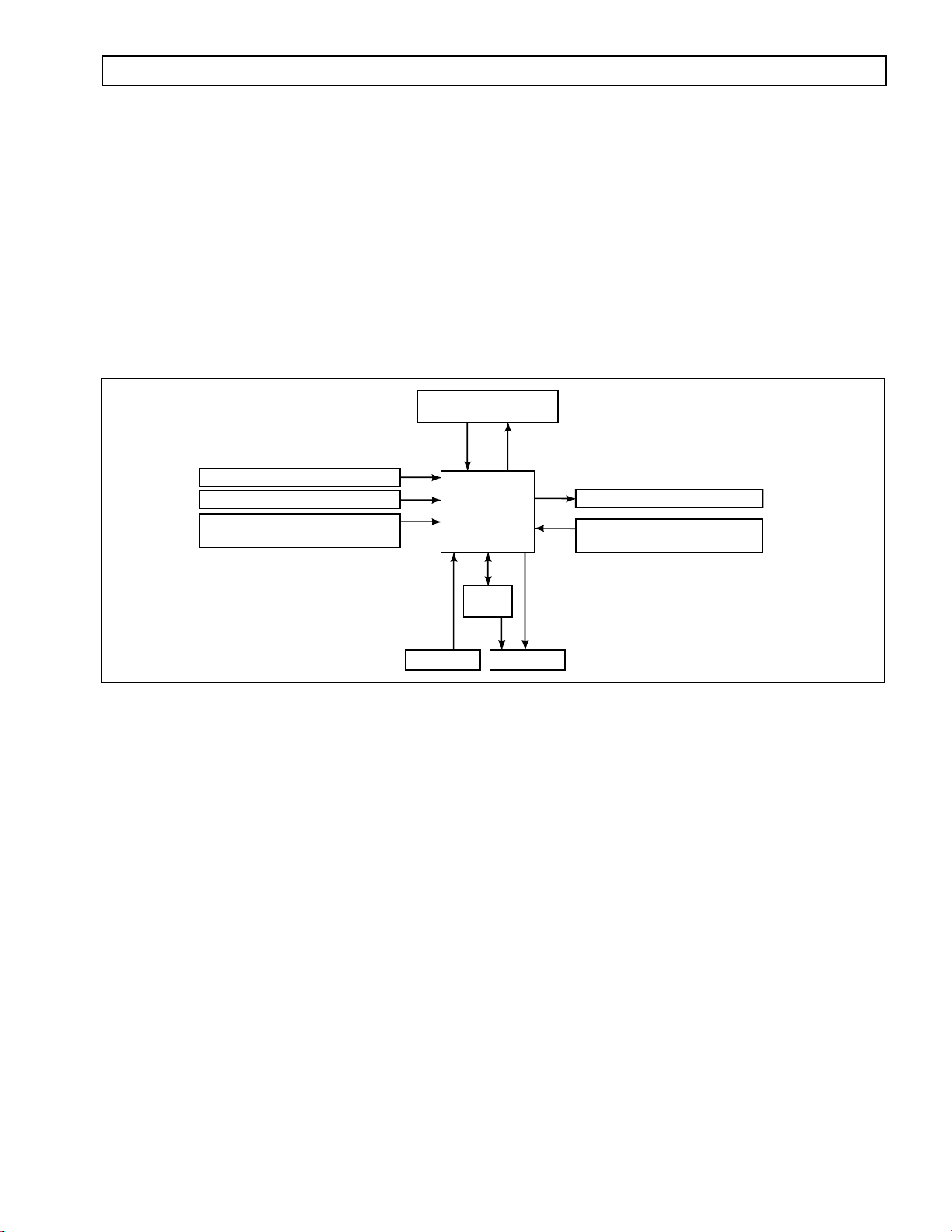
Figure 1–1 is a block diagram of the basic system inputs and outputs.
Figure 1–1. Electronic Control Unit Block Diagram
Figure 1–2 shows the CEC 2 electronic control components.
CEC 2 consists of the following elements:
Remote 12/24V Max Feature Sealed Electronic Control Unit (ECU)
•
•
Remote Pushbutton or Lever Shift Selector
•
Optional Secondary Shift Selector
Throttle Position Sensor (TPS) (or electronic engine throttle data)
•
•
Input, Turbine, and Output Speed Sensors
Electro-Hydraulic Valve Bodies
•
Wiring Harnesses
•
•
Vehicle Interface Module (VIM)
NOTE:
•
All external harnesses are OEM supplied
The VIM is an OEM option
•
Copyright © 2000 General Motors Corp. 1–1
Page 11
BLUE
BLUE
BLACK
GRA
COMMERCIAL ELECTRONIC CONTROLS 2 (CEC 2) TROUBLESHOOTING MANUAL
GENERAL DESCRIPTION
ELECTRONIC
CONTROL
UNIT
(ECU)
SELECTOR (S)
HARNESS
®
PRO-LINK
DIAGNOSTIC
REMOTE
SELECTOR
TOOL
LEVER
BLACK
B
“S”
CONNECTOR
(BLACK)
DIAGNOSTIC
DATA READER (DDR)
CONNECTOR
DEUTSCH DDR
CONNECTOR
SCI (J 1587)
CONNECTOR
(OPTIONAL)
(OPTIONAL)
LUE
Y
A
GR
E
BLU
J 1939
CONNECTOR
(OPTIONAL)
TRANSMISSION (T)
HARNESS
“T”
CONNECTOR
(BLUE)
VIW–S
CONNECTOR
“V”
CONNECTOR
(GRAY)
TPS
CONNECTOR
(OPTIONAL)
VEHICLE
INTERFACE
MODULE
(VIM)
TRIM
BOOST
CONNECTOR
VEHICLE (V)
HARNESS
CONNECTOR
VIM
CONNECTORS
VIW–V
PUSHBUTTON
.
REMOTE
SELECTOR
T
C
E
L
E
S
SHIFT
SELECTOR
CONNECTOR
THROTTLE POSITION
E
D
O
M
R
N
D
THROTTLE
POSITION
SENSOR (TPS)
SENSOR (TPS)
CONNECTOR
SPEED SENSOR
CONNECTOR
TURBINE
INPUT (ENGINE)
SPEED SENSOR
CONNECTOR
Bulkhead Connector (Optional)
NOTE: Illustration is not to scale. Actual harness
configuration may differ from this illustration.
TEMP SENSOR/
LOCKUP
CONNECTOR
SPEED SENSOR
CONNECTOR
TRANSMISSION
MAIN VALVE
BODY
CONNECTOR
OUTPUT
V06587
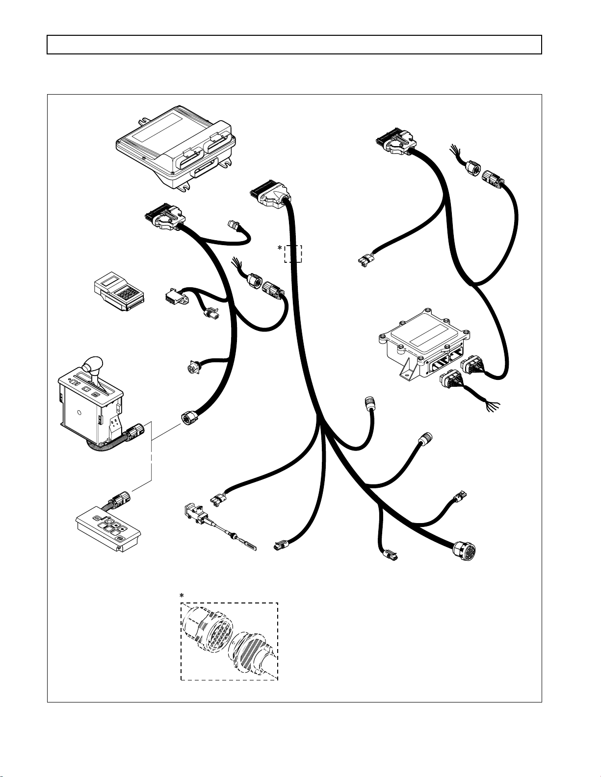
Figure 1–2. CEC 2 Components
1–2 Copyright © 2000 General Motors Corp.
Page 12
BLUE
BLUE
BLACK
GRA
⇑
⇓
⇑
COMMERCIAL ELECTRONIC CONTROLS 2 (CEC 2) TROUBLESHOOTING MANUAL
GENERAL DESCRIPTION
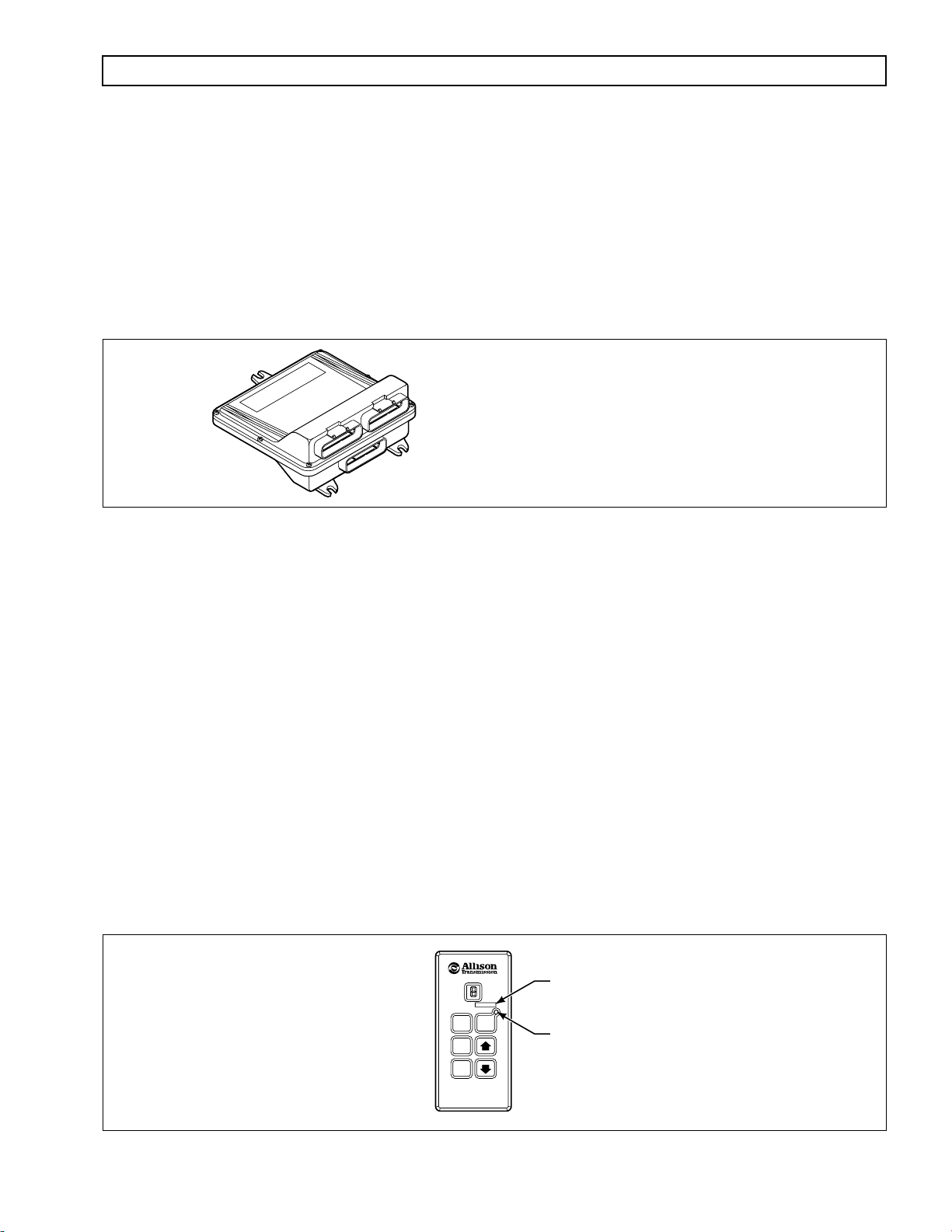
1–2. ELECTRONIC CONTROL UNIT (ECU)
The ECU (Figure 1–3) contains the microcomputer which is the brain of the control system. The ECU receives and
processes information defining: shift selector position, throttle position, sump temperature, input speed, turbine
speed, and transmission output speed. The ECU uses the information to control transmission solenoids and valves,
supply system status, and provide diagnostic information.
Each ECU has a date code stamped on the label which is attached to the outer case of the ECU. This is the date
when the ECU passed final test. This date is commonly used to denote the change configuration level of the ECU.
It is normal for the ECU date displayed electronically to be a few days prior to the date shown on the label.
Y
A
R
G
NOTE: ECU wiring harness connector retainers
are individually keyed and color-coded to
ensure that the proper connector is attached
K
C
A
L
B
BLUE
to the correct ECU socket. The color of the
connector retainer should match the color of
the connector strain relief (see Appendix C,
BLUE
ECU
Paragraph 1–1).
Figure 1–3. Electronic Control Unit (ECU)
V03352.01
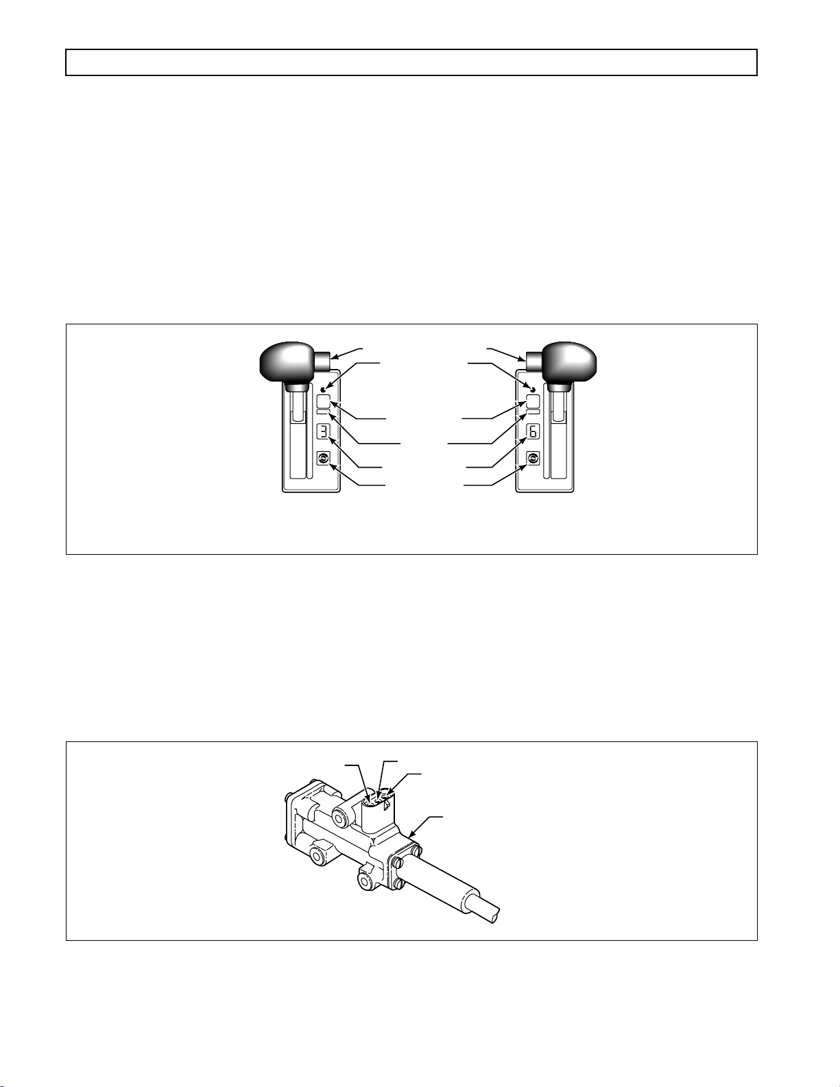
1–3. SHIFT SELECTOR
Pushbutton and lever shift selectors for CEC 2 are remote mounted from the ECU and connected to the ECU by a
wiring harness. Both of these shift selectors have a single digit LED display and a mode indicator LED. During
normal transmission operation, illumination of the LED indicator shows that a secondary or special operating
condition has been selected by pressing the MODE button. During diagnostic display mode, illumination of the
LED indicator shows that the displayed diagnostic code is active. Display brightness is regulated by the same
vehicle potentiometer that controls dash light display brightness. More information on both types of shift selectors
is continued below.
A. Pushbutton Shift Selector (Figure 1–4)
There is a full-function pushbutton shift selector. A full-function shift selector has a MODE button
and diagnostic display capability through the single digit LED display. The full-function pushbutton
shift selector has six (6) pushbuttons which are R (Reverse), N (Neutral), D (Drive), ⇓ (Down),
(Up), and MODE . Manual forward range downshifts and upshifts are made by pressing the
(Down) or ⇑ (Up) arrow buttons after selecting D (Drive). The N (Neutral) button has a raised lip to
aid in finding it by touch. The MODE button is pressed to select a secondary or special operating
condition, such as ECONOMY shift schedule. Diagnostic information is obtained by pressing the
(Up) and ⇓ (Down) arrow buttons at the same time.
MODE ID
MODE
R
N
D
MODE INDICATOR (LED)
PUSHBUTTON
SELECTOR
Figure 1–4. Pushbutton Shift Selector
Copyright © 2000 General Motors Corp. 1–3
V06588
Page 13
COMMERCIAL ELECTRONIC CONTROLS 2 (CEC 2) TROUBLESHOOTING MANUAL
GENERAL DESCRIPTION
B. Lever Shift Selector (Figure 1–5)
The lever shift selector can have as many as six forward range positions, as well as two R (Reverse)
positions ( R1 and R2 ) and N (Neutral). There is a hold override button which must be pressed and
held in order to move between certain selector positions. The hold override button must be pressed
when shifting between R , N, and D . The hold override button is released when the desired selector
position is reached. The selector lever can be moved freely between D and the numbered forward
ranges without pressing the hold override button. The lever selector can be chosen with the lever on
the left side or on the right side and with the R (Reverse) position toward the front or toward the rear
of the selector. Diagnostic information is obtained from the single digit LED display by pressing the
“display mode” button.
HOLD OVERRIDE BUTTON
MODE INDICATOR
(LED)
1
MODE
2
3
4
5
D
N
R
SIX-SPEED, LEFT-HAND
LEVER SELECTOR
WITH REVERSE TO REAR
MODE BUTTON
MODE ID
DIGITAL DISPLAY
DISPLAY MODE/
DIAGNOSTIC BUTTON
SIX-SPEED, RIGHT-HAND
LEVER SELECTOR
WITH REVERSE TO FRONT
R
MODE
N
D
5
4
3
2
1
V03355.02
Figure 1–5. Typical Lever Shift Selector
1–4. THROTTLE POSITION SENSOR (Figure 1–6)
The Throttle Position Sensor (TPS) can be mounted to the engine, chassis, or transmission. The TPS contains a pull
actuation cable and a potentiometer. One end of the cable is attached to the engine fuel lever and the other , inside a
protective housing, to the TPS potentiometer. Output voltage from the TPS is directed to the ECU through the
external harness. The voltage signal indicates the throttle position and, in combination with other input data,
determines shift timing.
A
Figure 1–6. Throttle Position Sensor
B
C
THROTTLE SENSOR
V00628
1–4 Copyright © 2000 General Motors Corp.
Page 14
COMMERCIAL ELECTRONIC CONTROLS 2 (CEC 2) TROUBLESHOOTING MANUAL
GENERAL DESCRIPTION
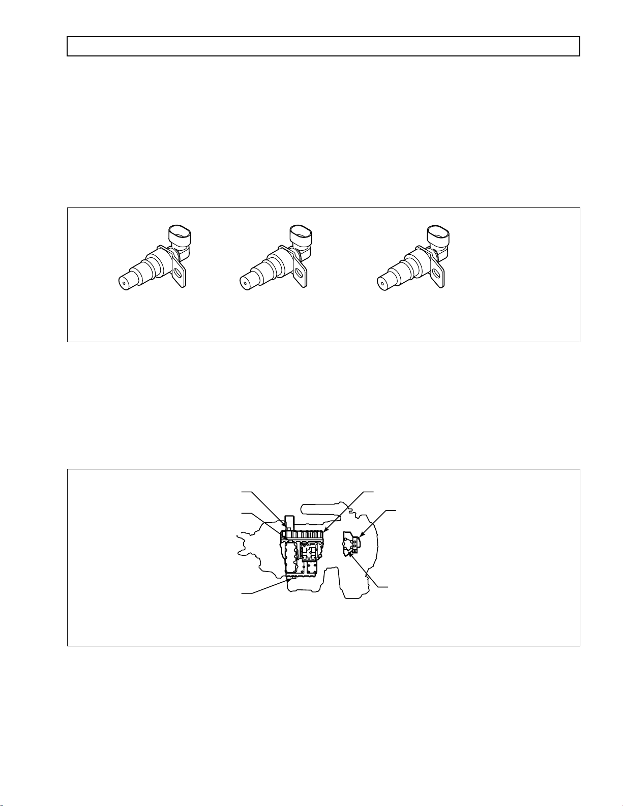
1–5. SPEED SENSORS
(Figure 1–7)
Three speed sensors — input speed, turbine speed, and output speed — provide information to the ECU. The input
speed signal is generated by the gear teeth on the top PTO gear . The turbine speed signal is generated by serrations
on the pitot can attached to the splitter low drum. The output speed signal is generated by a toothed member
attached to the output shaft. The speed ratios between the various speed sensors allow the ECU to determine if the
transmission is in the selected range. Hydraulic problems are detected by comparing the speed sensor information
for the current range to that range’s speed sensor information stored in the ECU memory.
INPUT
(EXTERNAL)
TURBINE
(EXTERNAL)
Figure 1–7. Speed Sensors
OUTPUT
(EXTERNAL)
V06589
1–6. ELECTRO-HYDRAULIC VALVE COMPONENTS (Figure 1–8)
The CEC 2 electro-hydraulic valve bodies contain v arious solenoids to control the absence or presence of solenoid
pressure. Solenoid pressure, or lack of pressure, positions shift valves which apply or release transmission clutches
to produce the range commanded by the ECU inputs. The ECU is connected to the solenoids by a wiring harness
with sealed multi-pin twist-lock connectors at the control valve bodies.
(Solenoids A – G)
PLATE & COVER CONNECTOR
(Solenoids H, I, & J)
8610, 9610, 9810
TRIM BOOST CONNECTOR
(Solenoid J)
5610, 6610
5/6/8/9000 SERIES OFF-HIGHWAY TRANSMISSION
Figure 1–8. CEC 2 Control Module
MAIN VALVE BODYMAIN CONNECTOR – ALL MODELS
LOCKUP VALVE BODY
LOCKUP CONNECTOR – ALL MODELS
(K Solenoid and sump
temperature sensor)
V06590
Copyright © 2000 General Motors Corp. 1–5
Page 15

a
COMMERCIAL ELECTRONIC CONTROLS 2 (CEC 2) TROUBLESHOOTING MANUAL
GENERAL DESCRIPTION
The sump temperature sensor in the lockup body sends information to the ECU. When oil temperature is below
–25ºF (–32ºC), all shifts are blocked. When oil temperature is between –25ºF
transmission shifting is limited to neutral, to limited forward ranges
a
, and reverse. Above 250ºF
a
(–32ºC) and 20ºF
a
(–7ºC),
a
(121ºC), the Hot
light comes on (if equipped), and a trouble code is stored in memory. See chart in Section 5, Code 24 for sump
temperature sensor (thermistor) characteristics. Some applications (emergency vehicles, for example) are often
exempt from shift inhibit during temperature extremes, b ut the
CHECK TRANS
light may still come on and codes
may be logged in the ECU memory.
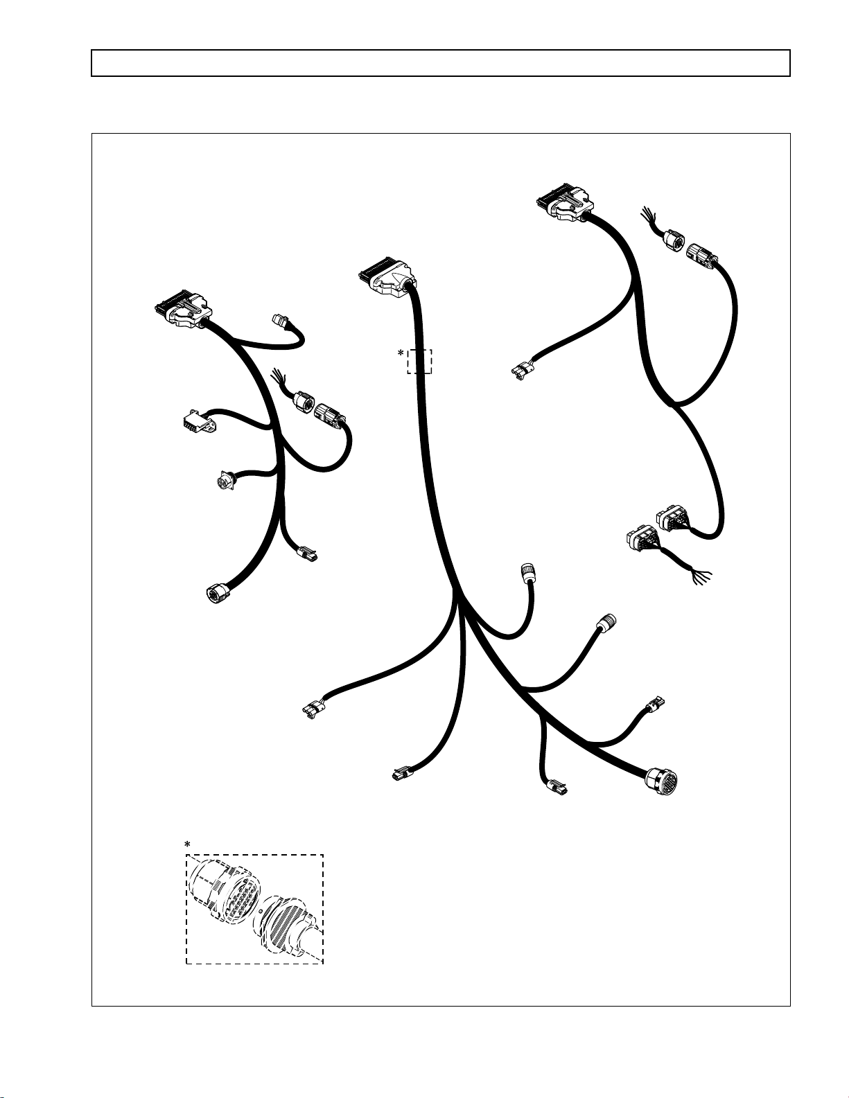
1–7. WIRING HARNESSES
A. External Wiring Harness (Figure 1–9)
CEC 2 uses three external wiring harnesses to provide a connection between the ECU, the
transmission (including input, turbine, and output speed sensors), the throttle position sensor, the
vehicle interface module (VIM), shift selectors, diagnostic tool connector, and vehicle interface. The
transmission harness may include a bulkhead fitting to separate cab and chassis components.
NOTE: Allison Transmission is providing for service of wiring harnesses and wiring harness components as
follows:
•
Repair parts for the internal wiring harness and for wiring harness components attached to the
shift selector will be available through the Allison Transmission Parts Distribution Center
(PDC). Use the P/N from your appropriate parts catalog or from Appendix C in this manual.
Allison Transmission is responsible for warranty on these parts.
Repair parts for the external harnesses and external harness components must be obtained from
•
St. Clair Technologies Inc. (SCTI). SCTI provides parts to any Allison customer or OEM and is
responsible for warranty on these parts. SCTI recognizes ATD, manufacturers, and SCTI part
numbers. SCTI provides a technical HELPLINE at 519-627-1673 (Wallaceburg). SCTI will have
parts catalogs available. The SCTI addresses and phone numbers for parts outlets are:
St. Clair Technologies, Inc.
1050 Old Glass Road
Wallaceburg, Ontario N8A 3T2
Phone: (519) 627-1673
Fax: (519) 627-4227
St. Clair Technologies, Inc.
1111 Mikesell Street
Charlotte, MI 48813
Phone: (517) 541-8166
Fax: (517) 541-8167
St. Clair Technologies, Inc.
c/o Mequilas Tetakawi
Carr. Internationale KM 1969
Guadalajara – Nogales, KM2
Empalme, Sonora, Mexico
Phone: 011-52-622-34661
Fax: 011-52-622-34662
•
St. Clair Technologies, Inc. stocks a CEC 2 external harness repair kit, P/N 29532362, as a source
for some external harness repair parts. SCTI is the source for external harness repair parts.
This is a programmed value subject to change.
1–6 Copyright © 2000 General Motors Corp.
Page 16
COMMERCIAL ELECTRONIC CONTROLS 2 (CEC 2) TROUBLESHOOTING MANUAL
GENERAL DESCRIPTION
VEHICLE (V)
HARNESS
SELECTOR (S)
HARNESS
“S”
CONNECTOR
(BLACK)
PRO-LINK®
DIAGNOSTIC
DIAGNOSTIC
TOOL
DATA READER (DDR)
CONNECTOR
DEUTSCH DDR
CONNECTOR
(OPTIONAL)
SHIFT
SELECTOR
CONNECTOR
J 1939
CONNECTOR
(OPTIONAL)
TRANSMISSION (T)
VIW–S
CONNECTOR
SCI (J 1587)
CONNECTOR
(OPTIONAL)
HARNESS
CONNECTOR
(BLUE)
“T”
“V”
CONNECTOR
(GRAY)
TPS
CONNECTOR
(OPTIONAL)
TRIM
BOOST
CONNECTOR
VIM
CONNECTORS
TEMP SENSOR/
LOCKUP
CONNECTOR
VIW–V
CONNECTOR
THROTTLE POSITION
SENSOR (TPS)
CONNECTOR
Bulkhead Connector (Optional)
OUTPUT
SPEED SENSOR
CONNECTOR
TURBINE
SPEED SENSOR
CONNECTOR
NOTE: Illustration is not to scale. Actual harness
configuration may differ from this illustration.
INPUT (ENGINE)
SPEED SENSOR
CONNECTOR
TRANSMISSION
MAIN VALVE
BODY
CONNECTOR
V06591
Figure 1–9. CEC 2 External Wiring Harnesses
Copyright © 2000 General Motors Corp. 1–7
Page 17

COMMERCIAL ELECTRONIC CONTROLS 2 (CEC 2) TROUBLESHOOTING MANUAL
GENERAL DESCRIPTION
B. Internal Wiring Harnesses (Figure 1–10)
The internal wiring harnesses provide connection between the external harness, solenoids, and the
temperature sensor.
INTERNAL
HARNESS
A
B
C
D
E
F
INTERNAL
HARNESS
G
LOCKUP BODY
ALL MODELS
MAIN BODY SOLENOIDS & COVER
ALL MODELS
TRIM BOOST PLATE & COVER
9610 MODEL
J SOLENOID CONNECTOR
INTERNAL
HARNESS
INTERNAL
HARNESS
FIRST or LOW-LOW PLATE & COVER
8610, 9810 MODEL
INTERNAL
HARNESS
TRIM BOOST TRIMMER COVER
5610, 6610 MODEL
Figure 1–10. CEC 2 Internal Wiring Harnesses
1–8 Copyright © 2000 General Motors Corp.
L06592
Page 18
COMMERCIAL ELECTRONIC CONTROLS 2 (CEC 2) TROUBLESHOOTING MANUAL
GENERAL DESCRIPTION
a
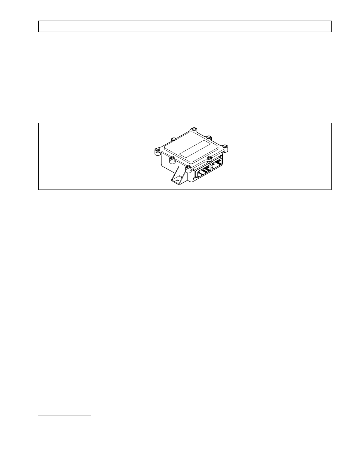
1–8. VEHICLE INTERFACE MODULE
(Figure 1–11)
The vehicle interface module (VIM) provides relays, fuses, and connection points to interface with the vehicle
electrical system. VIMs are available for both 12V and 24V electrical systems. The VIM for 12V systems uses all
12V relays. The VIM for 24V systems has all 24V relays. Refer to the P arts Catalog for the transmission assembly
number that you are servicing for detailed parts information. Refer to Pages B–19 and B–20 for VIM wire number
and terminal information. Further information is available in Appendix E.
Some OEMs may provide their own equi valent for the VIM which performs the same functions as the VIM shown
in Figure 1–11.
V00631.02
Figure 1–11. Vehicle Interface Module (VIM)
1–9. AUTODETECT FEATURE
Autodetect is active on the first 10
a
engine starts. Autodetect takes place within the first 5–25
engine start monitored. For CEC 2, autodetect searches for the presence of a throttle information source.
Autodetect searches for a TPS (analog) source or a data link source via J1939 or J1587.
a
seconds of each
This is a programmed value subject to change.
Copyright © 2000 General Motors Corp. 1–9
Page 19

COMMERCIAL ELECTRONIC CONTROLS 2 (CEC 2) TROUBLESHOOTING MANUAL
GENERAL DESCRIPTION
NOTES
1–10 Copyright © 2000 General Motors Corp.
Page 20

COMMERCIAL ELECTRONIC CONTROLS 2 (CEC 2) TROUBLESHOOTING MANUAL
S
ECTION
2 — DEFINITIONS AND ABBREVIATIONS
2–1. CHECK TRANS LIGHT
When the ECU detects an abnormal condition, the
instrument panel) illuminates and action is automatically taken to protect operator, v ehicle, and the transmission. A
diagnostic code will nearly always be registered when the
codes will turn on the
CHECK TRANS
light. Codes related to the
chart (refer to Section 5).
Illumination of the
CHECK TRANS
light indicates that a condition was detected that requires service attention.
Operation of the transmission may or may not be restricted. Depending upon the cause for the
light illumination, the ECU may or may not respond to shift selector requests. The transmission may be locked in a
range. The range selected will flash on the shift selector display. Both upshifts and downshifts may be restricted
when the
Each time the engine is started, the
CHECK TRANS
light is illuminated. Seek service assistance as soon as possible.
CHECK TRANS
lighting shows the light circuit is working properly. If the light does not come on during engine start, request
service immediately.
2–2. DIAGNOSTIC DATA READER
The current Diagnostic Data Reader (DDR) is the Pro-Link® 9000 diagnostic tool which is available through
Micro Processor Systems, Inc. (MPSI). A portable microcomputer-based receiver/transmitter/display unit, the
Pro-Link® transmits and receives data to and from the ECU, processes the data, and displays appropriate
information. Use the Pro-Link® during installation checkout and troubleshooting. There is a new Pro-Link®
cartridge needed for use with CEC 2. The new Multi-Protocol Cartridge (MPC) contains a programmed PCMCIA
card which allows for reprogramming of GPI/GPO packages. Reprogramming includes selection of a GPI/GPO
package, enabling/disabling of wires and modification of certain data parameters. Operating instructions are
supplied with each Pro-Link
Pro-Link
®
9000 to the diagnostic connector provided in the selector wiring harness.
Manufacturer’s description and part numbers for the Pro-Link
®
and further information is also included in Appendix J of this manual. Connect the
CHECK TRANS
CHECK TRANS
light illuminates briefly and then goes off. This momentary
Figure 2–1)
(
light (usually located on the vehicle
CHECK TRANS
®
are as follows:
light is on; howev er , not all diagnostic
light are detailed in the code
CHECK TRANS
Product Part Number
Allison CEC 1 and 2 transmission systems reprogramming card*
800007
Includes: Allison CEC 1 and 2 systems card and manual
* Allison training certificate required
Pro-Link
Multi-Protocol Cartridge (MPC)
®
Plus main unit
Includes: VT Pro-Link
®
software, power and data cable, and storage case
108004
208040
Supports: J1708, J1939, 160 baud, and ISO 9141 communications,
OEM specific application memory cards
Printer
178001
Includes: One roll of thermal paper, an AC power converter,
Instruction manual, built-in Ni-Cad battery and a cable to connect
the printer to the Pro-Link
®
Plus
6-Pin Deutsch Adapter 404024
PC/Terminal Cable Set
501005
Required to update PC card application
Pro-Link
®
9000 Operator’s Manual 950007
Copyright © 2000 General Motors Corp. 2–1
Page 21

A
C
C
C
D
D O N
D
C
D
E
G
G
L
COMMERCIAL ELECTRONIC CONTROLS 2 (CEC 2) TROUBLESHOOTING MANUAL
DEFINITIONS AND ABBREVIATIONS
NOTE: The new MPC must be used to reprogram CEC 2 systems.
Figure 2–1. Pro-Link
®
9000 Diagnostic Tool
V04842
2–3. ABBREVIATIONS
A/N
Amp Unit of electrical current.
CAN
CEC 1/CEC 2
COP
CT
DDR
DDU
DNS
DVOM
ssembly N umber
ontroller A rea N etwork — A network for all SAE J1939 communications in a vehicle
(engine, transmission, etc.)
ommercial E lectronic C ontrols 1 or 2 — Designation for electronic controls used in
off-highway and some older on-highway transmissions.
omputer O perating P roperly — Hardware protection which causes the ECU to reset if
software gets lost.
losed T hrottle
iagnostic D ata R eader — Diagnostic tool; most current version is the Pro-Link
made by MicroProcessor Systems, Inc. Used to interrogate the ECU for diagnostic
information and for reprogramming I/O packages in a calibration.
igital D isplay U nit — Optional means of obtaining diagnostic information.
OT S HIFT — Refers to the DO NOT SHIFT diagnostic response during which the
CHECK TRANS light is illuminated and the transmission will not shift and will not
respond to the Shift Selector.
igital v olt/ o hm m eter
®
9000
ECU
GPI
lectronic C ontrol U nit (also commonly referred to as the “computer”)
eneral P urpose I nput — Input signal to the ECU to request a special operating mode or
condition.
GPO
eneral P urpose O utput — Output signal from the ECU to control vehicle components
(such as PTOs, backup lights, etc.) or allow a special operating mode or condition.
J1587 Engine/transmission serial data communications link.
J1939 High-speed vehicle serial data communications link.
LED
2–2 Copyright © 2000 General Motors Corp.
ight- E mitting D iode — Electronic device used for illumination.
Page 22

N
O
P
P
P
P
P
S
S
S
COMMERCIAL ELECTRONIC CONTROLS 2 (CEC 2) TROUBLESHOOTING MANUAL
DEFINITIONS AND ABBREVIATIONS
T
V
V
V
V
V
2–3. ABBREVIATIONS
NVL
OEM
Ohm Unit of electrical resistance.
PCCS
PCMCIA
PROM
PSS
PTO
SCI
SOL OFF All SOL enoids OFF
SPI
SSS
eutral V ery L ow — The ECU has sensed turbine speed below 150 rpm when output
speed is below 100 rpm and engine speed is above 400 rpm when N (Neutral) was selected.
riginal E quipment M anufacturer — Maker of vehicle or equipment.
ROM C alibration C onfiguration S ystem
ersonal C omputer M emory C ard I nternational A ssociation — Memory device for use
with Pro-Link
rogrammable R ead O nly M emory
rimary S hift S elector — Main shift selector in a two-selector control system.
ower T ake o ff
erial C ommunication I nterface — Used to transmit data and messages between the
diagnostic tool and the ECU and other systems such as electronically-controlled engines.
erial P eripheral I nterface — The means of communication between the microprocessor
and the interface circuits.
econdary S hift S elector — Alternate shift selector in a two-selector control system.
(cont’d)
®
containing Allison Transmission programming and diagnostics.
TPS
V
V
VDC
VIM
VIW
Volt Unit of electrical force.
VOM
WOT
∞
hrottle P osition S ensor — Potentiometer for signaling the position of the engine fuel
control lever.
ersion — Abbreviation used in describing ECU software levels.
olt — i.e., 24V
olts D irect C urrent (DC)
ehicle I nterface M odule — A w atertight box containing relays and fuses — interfaces the
transmission electronic control system with components on the vehicle.
ehicle I
the vehicle wiring.
V
olt/ohmmeter
W
Infinity — Condition of a circuit with higher resistance than can be measured, effectively
an open circuit.
nterface Wiring — Interfaces ECU programmed input and output functions with
ide Open Throttle
Copyright © 2000 General Motors Corp. 2–3
Page 23

COMMERCIAL ELECTRONIC CONTROLS 2 (CEC 2) TROUBLESHOOTING MANUAL
DEFINITIONS AND ABBREVIATIONS
NOTES
2–4 Copyright © 2000 General Motors Corp.
Page 24

COMMERCIAL ELECTRONIC CONTROLS 2 (CEC 2) TROUBLESHOOTING MANUAL
S
ECTION
3 — BASIC KNOWLEDGE
3–1. BASIC KNOWLEDGE REQUIRED
T o service CEC 2, the technician must understand basic electrical concepts. Technicians need to know how to use a
volt/ohmmeter (VOM) to mak e resistance and continuity checks. Most troubleshooting checks consist of checking
resistance, continuity, and checking for shorts between wires and to ground. The technician should be able to use
jumper wires and breakout harnesses and connectors. Technicians unsure of making the required checks should ask
questions of experienced personnel or find instruction.
The technician should also have the mechanical aptitude required to connect pressure gauges or transducers to
identified pressure ports used in the troubleshooting process. Pressure tap locations and pressure values are shown
in the Service Manual for the transmission being checked.
Input power , ground, neutral start circuitry, etc., can cause problems with electronic controls or vehicle functioning
and may not generate a diagnostic code. A working knowledge of CEC 2 vehicle installation is necessary in
troubleshooting installation-related problems.
Refer to Section 8 for information concerning performance complaints (non-code) troubleshooting. A complete
wiring schematic is shown in Appendix G. Refer to the CEC 2 Controls and Off-Highway Sales Tech Data Book
(SA3227EN) for information concerning electronic controls installation and the Installation Checklist. Reliable
transmission operation and performance depend upon a correctly installed transmission. Also review the
Installation Checklist in the Off-Highway Sales Tech Data Book (SA1861EN) to ensure proper installation.
NOTE: Allison Transmission is providing for service of wiring harnesses and wiring harness components as
follows:
Repair parts for the internal wiring harness and for wiring harness components attached to the
•
shift selector will be available through the Allison Transmission Parts Distribution Center (PDC).
Use the P/N from your appropriate parts catalog or from Appendix C in this manual. Allison
Transmission is responsible for warranty on these parts.
•
Repair parts for the external harnesses and external harness components must be obtained from
St. Clair Technologies Inc. (SCTI). SCTI provides parts to any Allison customer or OEM and is
responsible for warranty on these parts. SCTI recognizes ATD, manufacturers, and SCTI part
numbers. SCTI provides a technical HELPLINE at 519-627-1673 (Wallaceburg). SCTI will have
parts catalogs available. The SCTI addresses and phone numbers for parts outlets are:
St. Clair Technologies, Inc.
1050 Old Glass Road
Wallaceburg, Ontario N8A 3T2
Phone: (519) 627-1673
Fax: (519) 627-4227
•
St. Clair Technologies, Inc. stocks a CEC 2 external harness repair kit, P/N 29532362, as a source
for some external harness repair parts. SCTI is the source for external harness repair parts.
St. Clair Technologies, Inc.
1111 Mikesell Street
Charlotte, MI 48813
Phone: (517) 541-8166
Fax: (517) 541-8167
St. Clair Technologies, Inc.
c/o Mequilas Tetakawi
Carr. Internationale KM 1969
Guadalajara – Nogales, KM2
Empalme, Sonora, Mexico
Phone: 011-52-622-34661
Fax: 011-52-622-34662
Copyright © 2000 General Motors Corp. 3–1
Page 25

COMMERCIAL ELECTRONIC CONTROLS 2 (CEC 2) TROUBLESHOOTING MANUAL
BASIC KNOWLEDGE
3–2. USING THE TROUBLESHOO TING MANU AL
Use this manual as an aid to troubleshooting CEC 2. Every possible problem and its solution cannot be
encompassed by any manual. Howe ver , this manual does pro vide a starting point from which most problems can be
resolved.
3–3. SYSTEM OVERVIEW
CEC 2 functions are controlled by the ECU. The ECU reads shift selector range selection, output speed, and
throttle position to determine when to command a shift. When a shift occurs, the ECU monitors turbine speed,
output speed, and throttle position during the shift.
When the ECU detects an electrical fault, it logs a diagnostic code indicating the faulty circuit and may alter the
transmission operation to prevent or reduce damage.
When the ECU detects a non-electrical problem while trying to make a shift, the ECU may try that shift a second or
third time before setting a diagnostic code. Once that shift has been retried, and a fault is still detected, the ECU
sets a diagnostic code and holds the transmission in a lock-to-range mode of operation.
3–4. IMPORTANT INFORMATION IN THE TROUBLESHOOTING PROCESS
Before beginning the troubleshooting process, read and understand the following:
•
CEC 2 wire identification presents the wire number followed by the ECU terminal source
(i.e., 157-S30). If there is a letter suffix following the wire number, there is a splice between the ECU
source and wire destination (i.e., 116A-T19).
•
Shut off the engine and ignition before any harness connectors are disconnected or connected.
•
Remember to do the following when checking for shorts and opens:
Shorts: Minimize movement of wiring harnesses when looking for shorts. Shorts involve wire-to-
—
wire or wire-to-ground contacts and moving the harnesses may eliminate the problem.
—
Opens: Wiggle connectors, harnesses, and splices when looking for opens. This simulates vehicle
movements which occur during actual operation.
•
When disconnecting a harness connector, be sure that pulling force is applied to the connector itself and
not the wires extending from the connector.
•
Resistance checks involving the wiring between the ECU connectors and other components adds about
one ohm of resistance to the component resistance shown.
•
Inspect all connector terminals for damage. Terminals may have bent or lost the necessary tension to
maintain firm contact.
•
Clean dirty terminals or connectors with isopropyl alcohol and a cotton swab, or a good quality, nonresidue, non-lubricating, cleaning solvent such as LPS Electro Contact Cleaner
Electro Contact Cleaner
3–2 Copyright © 2000 General Motors Corp.
®
.
®
or LPS NoFlash
Page 26

COMMERCIAL ELECTRONIC CONTROLS 2 (CEC 2) TROUBLESHOOTING MANUAL
BASIC KNOWLEDGE
The cleaning solvent must not be chlorine based, contain petroleum distillates, or conduct
electricity. The cleaning solvent should evaporate quickly to prevent the possibility of
CAUTION:
condensation within the connectors. Always blow or shake any excess cleaner from the
connector before assembling it to its mating connector or hardware. Cleaner trapped in the
connector can affect the connector seal. (Refer to SIL 17-TR-94 for detailed information
on the recommended cleaners.)
CAUTION:
Diagnostic codes displayed after system power is turned on with a harness connector disconnected, can
•
Care should be taken when welding on a vehicle equipped with electronic controls. Refer
to Appendix E, Paragraph 1–1.
be ignored and cleared from memory. Refer to Section 5, Diagnostic Codes, for the code clearing
procedure.
3–5. BEGINNING THE TROUBLESHOO TING PROCESS
1. Begin troubleshooting by checking the transmission fluid level and ECU input voltage. Remember
that some problems may be temperature related. Do troubleshooting at the temperature level where
the problem occurs. Check diagnostic codes by:
•
Using the shift selector display. (See Paragraph 5–2 for code reading.)
Using the Pro-Link
•
2. When a problem exists but a diagnostic code is not indicated, refer to the Performance Complaint
Section (Section 8) for a listing of various electrical and hydraulic problems, their causes, and remedies.
3. If a diagnostic code is found in the ECU memory, record all available code information and clear the
active indicator (refer to Section 5).
®
9000 diagnostic tool.
4. Test drive the vehicle to confirm a diagnostic code or performance complaint.
•
If the code reappears, refer to the Diagnostic Code section (Section 5) and the appropriate code
chart. The Diagnostic Code section lists diagnostic codes and their description. Locate the
appropriate troubleshooting chart and follow the instructions.
If the code does not reappear, it may be an intermittent problem. Use the Pro-Link
•
®
and the code
display procedure described in Section 5. The code display procedure will indicate the number of
times the diagnostic code has occurred. Refer to the troubleshooting chart for possible cause(s) of
the problem.
Appendix A deals with the identification of potential circuit problems. Refer to Appendix A if a
•
circuit problem is suspected.
NOTE: Information concerning specific items is contained in the appendices located in the back of this
manual. The appendices are referred to throughout the manual.
Copyright © 2000 General Motors Corp. 3–3
Page 27

COMMERCIAL ELECTRONIC CONTROLS 2 (CEC 2) TROUBLESHOOTING MANUAL
BASIC KNOWLEDGE
NOTES
3–4 Copyright © 2000 General Motors Corp.
Page 28
COMMERCIAL ELECTRONIC CONTROLS 2 (CEC 2) TROUBLESHOOTING MANUAL
S
ECTION
4 — WIRE CHECK PROCEDURES
4–1. CHECKING OPENS, SHORTS BETWEEN WIRES, AND SHORTS-TO-GROUND
(Use Digital Volt/Ohmmeter J 34520-A and Jumper Wire Set J 39197)
NOTE: Please refer to Paragraph 3–5 to begin the troubleshooting process.
1. Make sure all connectors are tightly connected and re-check the circuit.
2. Disconnect and inspect all connectors.
3. Thoroughly clean corroded or dirty terminals. If dirty or corroded terminals are the probable cause of
the problems, reconnect the clean connectors and operate the vehicle normally. If the problem recurs,
proceed with Step (4).
The cleaning solvent must not be chlorine based, contain petroleum distillates, or
conduct electricity. The cleaning solvent should evaporate quickly to prevent the
CAUTION:
4. Review the CEC 2 wire numbering system described in Paragraph 3–4.
possibility of condensation within the connectors. Always blow or shake any excess
cleaner from the connector before assembling it to its mating connector or hardware.
Cleaner trapped in the connector can affect the connector seal. (Refer to SIL 17-TR-94
for detailed information on the recommended cleaners.)
5. If all connectors are clean and connected correctly, determine which wires in the chassis harness are
indicated by the diagnostic code. For example, Code 45 12, indicates a failure in the F solenoid
circuit — wires 102-T1 and 120-T4.
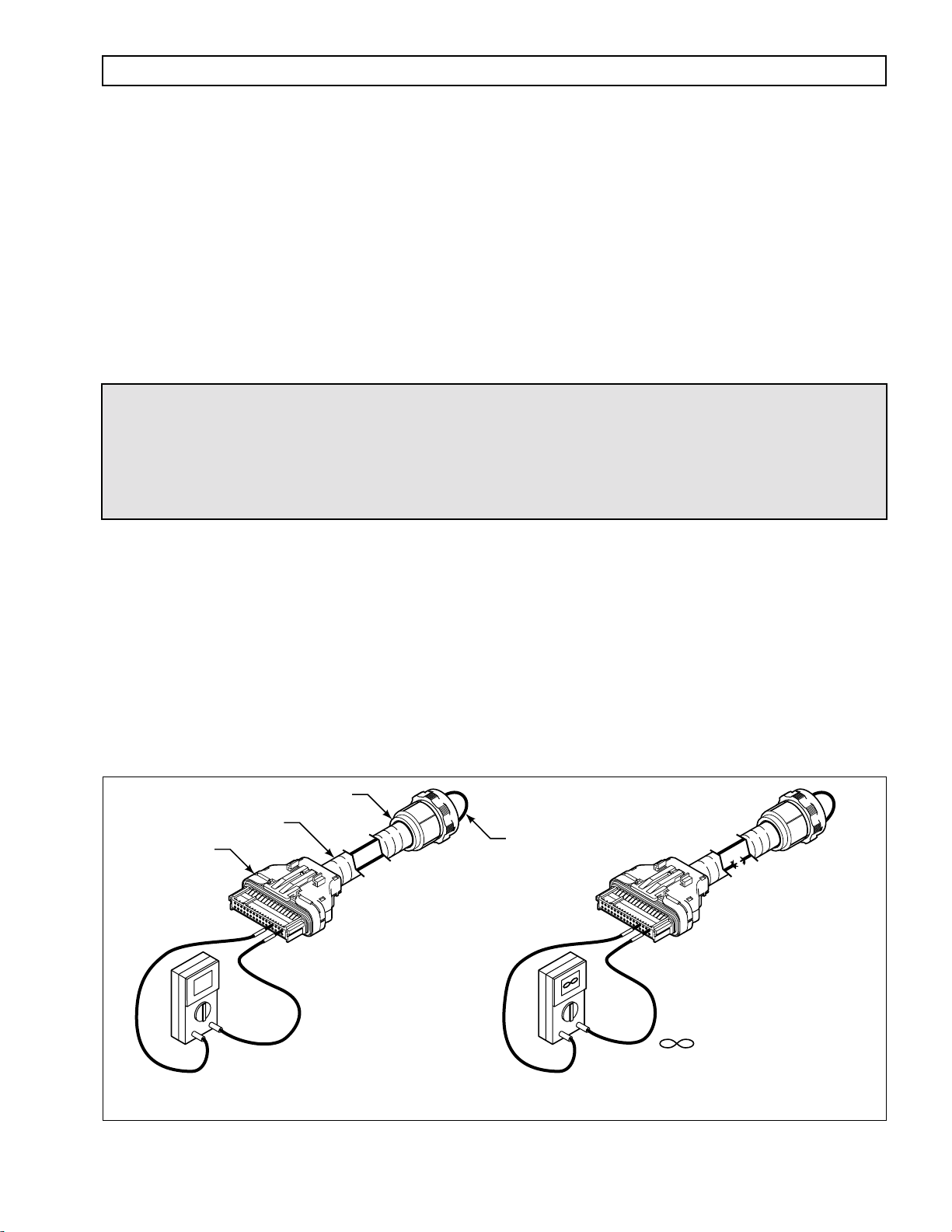
a. Check continuity of wires 102-T1 and 120-T4 by performing the following (refer to Figure 4–1):
(1) Disconnect the blue “T” connector from the ECU and disconnect the harness from the
transmission main connector. At one end of the harness, using jumper wire kit J 39197 and
connector probes in J 39775-CP, connect wire 102-T1 and 120-T4 to each other, being careful
not to distort the terminals. Jumping the wires together creates a circuit between wires 102-T1
and 120-T4.
TRANSMISSION CONNECTOR
WIRING HARNESS
“T” CONNECTOR
ECU
+
0
VOLT/OHM-
METER
–
(VOM)
JUMPER
–
+
0 OHMS OHMS
Circuit has continuity. Jumper
from 102 or 120 to another wire
produces a complete circuit. VOM
reading is near zero Ohms.
Circuit does not have continuity due
to a broken wire (open circuit).
VOM reading is very high
(infinite Ohms or OL – overlimit).
V03374.01
Figure 4–1. Open Circuit
Copyright © 2000 General Motors Corp. 4–1
Page 29
COMMERCIAL ELECTRONIC CONTROLS 2 (CEC 2) TROUBLESHOOTING MANUAL
WIRE CHECK PROCEDURES
(2) On the opposite end of the harness, check the continuity of the jumpered pair. No continuity in a
jumpered pair circuit (infinite resistance reading) indicates an open in the wire being tested.
Locate and repair the damaged portion of the wire.
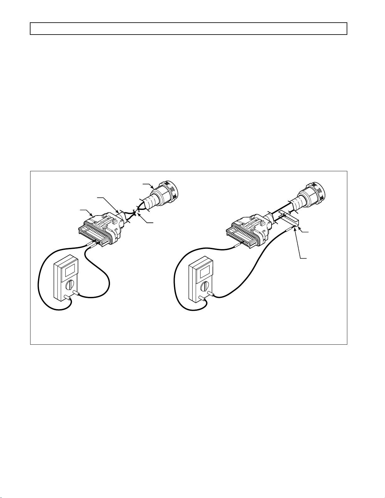
b. If the continuity check is good (0–2 Ohms resistance), remove the jumpers. Check the harness for
shorts between wires and shorts-to-ground by performing the following (refer to Figure 4–2):
(1) At the ECU end of the harness, touch one VOM probe to one wire of the circuit being tested
and touch the other probe to each terminal in the same connector, then touch the probe to chassis ground and to the transmission main housing. Do this for both wires in the circuit being
tested.
(2) If at any time the VOM shows zero to low resistance, or the meter’s continuity beeper sounds,
there is a short between the two points being probed — wire-to-wire or wire-to-ground. Isolate
and repair the short.
TRANSMISSION CONNECTOR
WIRING HARNESS
“T” CONNECTOR
ECU
0
+
VOLT/OHM-
METER
–
(VOM)
Wires shorted
together
Shorted to
ground on
metal frame
rail
Ground
to metal
0
–
+
frame rail
0 OHMS0 OHMS
Two wires have frayed and are shorted
together. Continuity beeper of VOM will
sound, or reading will go to zero Ohms
when these two wires are probed with
the VOM.
Figure 4–2. Short Between Wires or to Ground
Harness has been chafed and one or more
wires are shorted-to-ground. VOM continuity
beeper will sound, or reading will go to zero
Ohms when meter is probing between this wire
and chassis ground.
V03375
4–2. CHECKING AT TRANSMISSION CONNECTOR AND THE INTERNAL HARNESS
FOR OPENS, SHORTS BETWEEN WIRES, AND SHORTS-TO-GROUND
1. Disconnect the external wiring harness from the transmission.
2. Inspect the connectors. Any terminals which are corroded or dirty must be thoroughly cleaned.
3. If the connectors are clean and connected correctly, determine which wires in the harness to test.
Use the diagnostic code system schematic to locate the wire terminals. For this example, Code 45 12
indicates a failure in the F solenoid circuit — wires 102-T1 and 120-T4 (refer to Figure 4–3 and 4–4).
4–2 Copyright © 2000 General Motors Corp.
Page 30
COMMERCIAL ELECTRONIC CONTROLS 2 (CEC 2) TROUBLESHOOTING MANUAL
WIRE CHECK PROCEDURES
The cleaning solvent must not be chlorine based, contain petroleum distillates, or
conduct electricity. The cleaning solvent should evaporate quickly to prevent the
CAUTION:
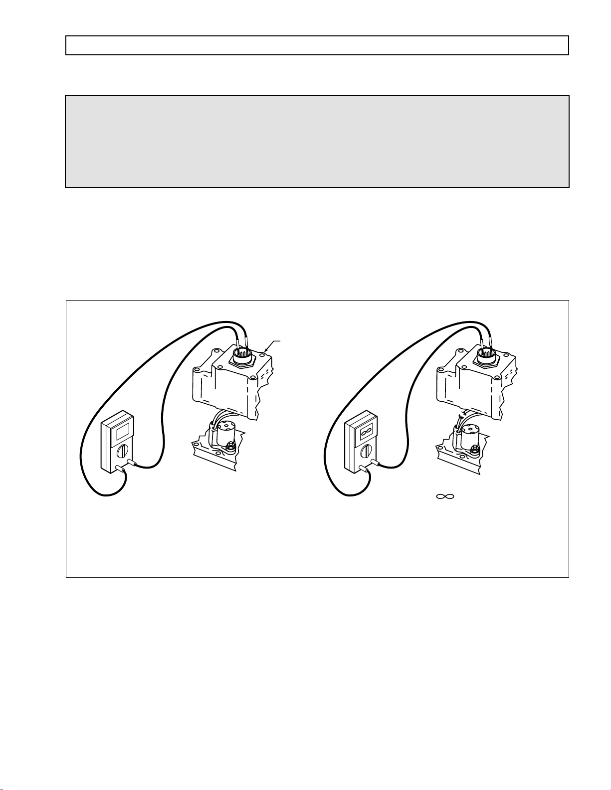
NOTE: Resistance of all solenoids (except J on 5610, 6610 models only) should be 12–24 Ohms. Solenoid J
resistance on the 5610, 6610 should be 10–13 Ohms.
a. At the transmission main valve body connector, check the resistance of the F solenoid circuit.
possibility of condensation within the connectors. Always blow or shake any excess
cleaner from the connector before assembling it to its mating connector or hardware.
Cleaner trapped in the connector can affect the connector seal. (Refer to SIL 17-TR-94
for detailed information on the recommended cleaners.)
Resistance of the solenoid circuit should be 12–24 Ohms. No continuity in the circuit (infinite
resistance) indicates an open in the internal harness, the feedthrough connector, or the solenoid
coil. Locate and repair the open in the internal harness or replace the internal harness, replace the
feedthrough connector, or replace the solenoid.
MAIN VALVE BODY
CONNECTOR
18
–
+
VOLT/OHM-
METER
(VOM)
12–24 OHMS
AT NORMAL OPERATING
TEMPERATURE*
Circuit has continuity.
* Refer to Appendix J
Figure 4–3. Checking Continuity
–
+
INFINITE ( ) OHMS
Circuit does not have continuity due to a
broken wire (open circuit). VOM reading is
very high (infinite ohms or OL–overlimit).
This could also be due to an open solenoid
coil or bad connection.
b. If the resistance check is good, check the harness for shorts between wires and to ground by per-
forming the following (refer to Figure 4–4):
V06593
(1) At the transmission connector, touch one probe of the VOM to one wire of the circuit being
tested and touch the other probe to each terminal in the connector and to chassis ground and
the transmission main housing. Do this for both wires in the circuit being tested.
(2) If the VOM shows zero to low resistance, or the continuity beeper sounds, there is a short
between the two points being probed, wire-to-wire or wire-to-ground. An indication of a short
may be caused by a splice to the wire being checked. Check the wiring diagram in Appendix G
for splice locations. If the short is not a splice, then isolate and repair the short.
Copyright © 2000 General Motors Corp. 4–3
Page 31

COMMERCIAL ELECTRONIC CONTROLS 2 (CEC 2) TROUBLESHOOTING MANUAL
WIRE CHECK PROCEDURES
MAIN VALVE BODY
CONNECTOR
Shorted
to metal
0
–
+
0
–
+
Bare wires
touching
each other
VOLT/OHM-
METER
(VOM)
0 OHMS0 OHMS
Two wires have frayed and are shorted
together. Continuity beeper of VOM will
sound, or reading will go to zero Ohms
when these two wires are probed with
the VOM.
Figure 4–4. Short Between Wires or to Ground
NOTE: When conducting circuit checks that include the external harness, add one (1) Ohm to the
values shown.
Harness has been chafed and one or more
wires are shorted to ground. VOM continuity
beeper will sound or meter reading will go
to zero Ohms when meter is probing between
this wire and chassis ground.
V06594
4–4 Copyright © 2000 General Motors Corp.
Page 32

COMMERCIAL ELECTRONIC CONTROLS 2 (CEC 2) TROUBLESHOOTING MANUAL
S
ECTION
5 — DIAGNOSTIC CODES
5–1. DIAGNOSTIC CODE MEMORY
Diagnostic codes are logged in a list in memory (sometimes referred to as the queue), listing the most recently
occurring code first and logging up to five codes. The codes contained in the list have information recorded as
shown in the table below (codes are examples). Access to the code list position, main code, subcode and active
indicator is through either the shift selector display or the Pro-Link® diagnostic tool. Access to ignition cycle
counter and event counter information is through the diagnostic tool only. Further detail on the use of
Pro-Link
Code List
Displayed on shift selector and diagnostic tool
d = “diagnostic”
®
9000 DDR is presented in Appendix J of this manual.
Table 5–1. Code List
Ignition Cycle
Position
d1
d2 45 12 YES 00 04
d3 23 12 YES 08 02
d4 34 12 YES 13 01
d5 56 11 YES 22 02
Main Code Subcode Active Indicator
21 12 YES 00 10
YES = LED indicator
illuminated
Counter
Not available on shift selector display
Event Counter
The following paragraphs define the different parts of the code list.
A. Code List Position.
“d1” through “d5” (Code List Position #1 through Code List Position #5).
B. Main Code.
C. Subcode.
D. Active Indicator.
selector is illuminated or the diagnostic tool displays
E. Ignition Cycle Counter.
the code list. The counter is increased by one each time a normal ECU power down occurs (ignition
turned off). Inactive codes are cleared from the code list after the counter exceeds 25.
F. Event Counter.
code list and the code is again detected, that code is moved to position d1, the active indicator is
turned on, the Ignition Cycle Counter is cleared, and 1 is added to the Event Counter.
The general condition or area of fault detected by the ECU.
The specific area or condition related to the main code in which a fault is detected.
The position which a code occupies in the code list. Positions are displayed as
Indicates when a diagnostic code is active. The MODE indicator LED on the shift
YES
.
Determines when inactive diagnostic codes are automatically cleared from
Counts the number of occurrences of a diagnostic code. If a code is already in the
5–2. CODE READING AND CODE CLEARING
Diagnostic codes can be read and cleared by two methods: by using the Pro-Link® 9000 diagnostic tool or by
entering the diagnostic display mode and using the shift selector display . The use of the Pro-Link
tool is described in the instruction manual furnished with each tool and briefly in Appendix J of this manual. The
method of reading and clearing codes described in this section refers to entering the diagnostic display mode by the
proper button movements on the shift selector.
®
9000 diagnostic
Copyright © 2000 General Motors Corp. 5–1
Page 33

COMMERCIAL ELECTRONIC CONTROLS 2 (CEC 2) TROUBLESHOOTING MANUAL
DIAGNOSTIC CODES
The diagnostic display mode may be entered for viewing of codes at any speed. Active codes can only be cleared
when the output speed = 0 and no output speed sensor failure is active.
A. Reading Codes. Enter the diagnostic display mode by pressing the ⇑ ( Up ) and ⇓ ( Down ) arrow
buttons at the same time on a pushbutton selector, or by momentarily pressing the “display mode”
button on a lever shift selector.
NOTE: If a DO NOT SHIFT condition is present (CHECK TRANS light illuminated) at this time, the shift
selector may or may not respond to requested range changes.
The code list or queue position is the first item displayed, followed by the main code and the subcode. Each item is
displayed for about one second. The display cycles continuously until the next code list position is accessed by
pressing the
MODE
button. The following list represents the display cycle using code 25 11 as an example:
1. Code list position — d,
2. Main code — 2,
3. Subcode —1,
4. Cycle repeats — d, 1, 2, 5, 1,
To view the second, third, fourth, and fifth positions (d2, d3, d4, and d5), momentarily press the
explained above.
Momentarily press the
positions.
An active code is indicated by the illumination of the LED indicator when a code position is displayed while in the
diagnostic display mode.
Any code position which does not have a diagnostic code logged will display “–” for both the main and subcodes.
No diagnostic codes are logged after an empty code position.
B. Clearing Active Indicators.
code inhibit to be cleared but remains in the queue as inactive.
The active indicator clearing methods are:
1. Power down — All active indicators, except code 69 34 (refer to the code chart), are cleared at
ECU power down.
MODE
5
1
button after the fifth position is displayed to restart the sequence of code list
1
1
MODE
A diagnostic code’s active indicator can be cleared, which allows the
button as
2. Self-clearing — Some codes will clear their active indicator when the condition causing the code
is no longer detected by the ECU.
3. Manual — Some active indicators can be cleared manually, while in the diagnostic display mode,
after the condition causing the code is corrected.
If an active indicator is cleared while the transmission is locked in a forward range
CAUTION:
5–2 Copyright © 2000 General Motors Corp.
(lock-to-range), the transmission will remain in the forward range after the clearing
procedure is completed. Neutral must be manually selected.
Page 34

D o N
•
COMMERCIAL ELECTRONIC CONTROLS 2 (CEC 2) TROUBLESHOOTING MANUAL
DIAGNOSTIC CODES
C. Manually Clearing Codes and Active Indicators fr om the Code List. To clear active indicators or
all codes:
1. Enter the diagnostic display mode.
2. Press and hold the MODE button for approximately three seconds until the LED indicator flashes.
All active indicators are cleared. To remove all inactive codes, press and hold the MODE button
for about ten seconds until the LED indicator flashes again. All active indicators will be cleared at
ECU power down.
3. Codes that cannot be manually cleared will remain.
D. Exiting the diagnostic display mode. Exit the diagnostic display mode using one of the following
procedures:
1. On a pushbutton shift selector, press the ⇑ ( Up ) and ⇓ ( Down ) arrow buttons at the same time or
press any range button, D, N, or R. The shift (D, N, or R) is commanded if not inhibited by an
active code.
2. On a le ver shift selector , momentarily press the “display mode” b utton or mov e the shift lev er to any
shift position other than the one it was in when the diagnostic display mode was activated. If the
shift is inhibited, the ECU will continue to command the current transmission range attained and the
lever should be returned to its original position.
3. Wait until timeout (approximately 10 minutes) and the system will automatically return to the
normal operating mode.
4. Turn off power to the ECU (turn off the vehicle engine at the ignition switch).
5–3. DIAGNOSTIC CODE RESPONSE
The following ECU responses to a fault provide for safe transmission operation:
•
•
ot S hift (DNS) Response
—
Release lockup clutch and inhibit lockup operation.
Inhibit all shifts.
—
—
Turn on the CHECK TRANS light.
—
Shift selector display flashes the range selected.
Ignore any range selection inputs from the pushbutton or lever shift selector.
—
SOL enoid OFF (SOL OFF) Response
—
All solenoids are commanded off.
5–4. SHIFT SELECTOR DISPLAYS RELATED TO ACTIVE CODES
“Cateye” — The forward slash segments and the middle horizontal segments (-\-) may be on under the
following conditions:
—
RSI link fault is active (code 23 12 or 23 14)
When two COP timeouts occur within two seconds of each other (reference code 69 33)
—
—
Shift selector display line fault is active (23 16)
Copyright © 2000 General Motors Corp. 5–3
Page 35

•
COMMERCIAL ELECTRONIC CONTROLS 2 (CEC 2) TROUBLESHOOTING MANUAL
DIAGNOSTIC CODES
All Segments Displayed — All display segments will be illuminated if a severity 1 diagnostic code is
present during initialization, or if an electrical code for any solenoid is logged before initialization
completes.
5–5. DIAGNOSTIC CODE LIST AND DESCRIPTION
Table 5–2. CEC 2 Diagnostic Codes
CHECK
Main
Code
Subcode Description
TRANS
Light
Inhibited Operation
Description
13
(pg 5–12)
21 12 Throttle position sensor, failed low Yes Use throttle default values
(pg 5–16) 23 Throttle position sensor, failed high Yes Use throttle default values
22
(pg 5–20)
23
(pg 5–24)
13 Primary shift selector mode function
12 ECU input voltage, low Yes DNS
23 ECU input voltage, high Yes DNS
14 Engine speed sensor reasonableness
test
15 Turbine speed sensor reasonableness
test
16 Output speed sensor reasonableness
test
12 Primary shift selector or RSI link fault Yes Hold in last valid direction. May cause
fault
14 Secondary shift selector or RSI link
fault
15 Secondary shift selector mode
function fault
Yes Use default engine speed
Yes DNS, lock in current range
Yes DNS, lock in current range
“cateye” display.
No Mode change not permitted
Yes Hold in last valid direction. May cause
“cateye” display.
No Mode change not permitted
16 Shift Selector display line fault Yes None. May cause “cateye” display.
24 12 Sump fluid temperature, cold Yes DNS, lock-to-range
(pg 5–26) 23 Sump fluid temperature, hot Yes No upshifts above a calibration range
25
(pg 5–30)
5–4 Copyright © 2000 General Motors Corp.
11 Output speed sensor, detected at
0 output rpm, 1st
22 Output speed sensor, detected at
0 output rpm, 2nd
33 Output speed sensor, detected at
0 output rpm, 3rd
Yes DNS, lock in current range (1st)
Yes DNS, lock in current range (2nd)
Yes DNS, lock in current range (3rd)
Page 36

COMMERCIAL ELECTRONIC CONTROLS 2 (CEC 2) TROUBLESHOOTING MANUAL
DIAGNOSTIC CODES
Table 5–2. CEC 2 Diagnostic Codes (cont’d)
CHECK
Main
Code
Subcode Description
TRANS
Light
Inhibited Operation
Description
25 (cont’d) 44 Output speed sensor, detected at
0 output rpm, 4th
55 Output speed sensor, detected at
0 output rpm, 5th
66 Output speed sensor, detected at
0 output rpm, 6th
77 Output speed sensor, detected at
0 output rpm, 7th
88 Output speed sensor, detected at
0 output rpm, 8th
26
(pg 5–33)
33
(pg 5–34)
34
(pg 5–37)
00 Throttle source not detected No Use throttle default values
12 Sump fluid temperature sensor failed
low
23 Sump fluid temperature sensor failed
high
12 Factory calibration compatibility
number wrong
13 Factory calibration fault Yes DNS, SOL OFF
Yes DNS, lock in current range (4th)
Yes DNS, lock in current range (5th)
Yes DNS, lock in current range (6th)
Yes DNS, lock in current range (7th)
Yes DNS, lock in current range (8th)
Yes Use default value of 93˚C (200˚F)
Yes Use default value of 93˚C (200˚F)
Yes DNS, SOL OFF
14 Power off fault Yes Use previous location, or factory
calibration
15 Diagnostic queue fault Yes Use previous location, or clear diagnostic
queue
16 Real time fault Yes DNS, SOL OFF
17 Customer modifiable constants fault Yes DNS, SOL OFF
35
(pg 5–38)
36
(pg 5–41)
45 12 General solenoid failure — F Yes DNS
(pg 5–42) 13 General solenoid failure — K Yes DNS, Inhibit lockup
00 Power interruption (code set after
power restored)
16 Real time write interruption Yes DNS, SOL OFF
00 Hardware/software not compatible Yes DNS, SOL OFF
14 General solenoid failure — B Yes DNS, Inhibit Reverse
No None (hydraulic default during
interruption)
Copyright © 2000 General Motors Corp. 5–5
Page 37

COMMERCIAL ELECTRONIC CONTROLS 2 (CEC 2) TROUBLESHOOTING MANUAL
DIAGNOSTIC CODES
Table 5–2. CEC 2 Diagnostic Codes (cont’d)
CHECK
Main
Code
45 (cont’d) 15 General solenoid failure — G Yes DNS
Subcode Description
16 General solenoid failure — E Yes DNS
21 General solenoid failure — H/J Yes Turn off trim boost J, DNS H
22 General solenoid failure — A Yes No action taken
23 General solenoid failure — D Yes DNS
24 General solenoid failure — I Yes No action taken
26 General solenoid failure — C Yes DNS
TRANS
Light
Inhibited Operation
Description
46 21 Hi side overcurrent, H/J solenoid Yes Turn off H/J solenoid, DNS 8610, 9810
(pg 5–46) 26 Hi side overcurrent, C, D, E solenoid
circuit
27 Hi side overcurrent, A, B, F, G, I, K
solenoid circuit
56 11 Range verification ratio test, 1st Yes DNS
(pg 5–48) 22 Range verification ratio test, 2nd Yes DNS
33 Range verification ratio test, 3rd Yes DNS
44 Range verification ratio test, 4th Yes DNS
55 Range verification ratio test, 5th Yes DNS
66 Range verification ratio test, 6th Yes DNS
77 Range verification ratio test, 7th or R1 Yes DNS
88 Range verification ratio test, 8th or R2 Yes DNS
65
(pg 5–50)
66
(pg 5–52)
00 Engine rating too high Yes DNS, Lock-in-neutral
00 Serial communications interface fault No Use default throttle values
Yes Turn off C, D, E solenoids
Yes DNS. Turn off A, B, F, G, I, K solenoids.
69
(pg 5–54)
5–6 Copyright © 2000 General Motors Corp.
27 ECU, inoperative A, B, F, G, I, K
solenoid
28 ECU, inoperative H/J solenoid Yes DNS, SOL OFF
29 ECU, inoperative C, D, E solenoid Yes DNS, SOL OFF
33 ECU, Computer Operating Properly
(COP) fault
Yes DNS, SOL OFF
Yes Reset ECU, shutdown ECU on 2nd
occurrence (power loss; hydraulic
defaults). May cause “cateye” display or
all segments blank display
Page 38

COMMERCIAL ELECTRONIC CONTROLS 2 (CEC 2) TROUBLESHOOTING MANUAL
DIAGNOSTIC CODES
Table 5–2. CEC 2 Diagnostic Codes (cont’d)
CHECK
Main
Code
69 (cont’d) 34 ECU, EEPROM, fault Yes DNS, SOL OFF
Subcode Description
35 ECU, EEPROM, fault Yes Reset ECU
39 Communication chip addressing error Yes Use defaults for J1939 data
42 SPI output failure No GPO 1–8 and reverse warning inoperable
43 SPI input failure Yes DNS, lock-in-range
TRANS
Light
Inhibited Operation
Description
Copyright © 2000 General Motors Corp. 5–7
Page 39

COMMERCIAL ELECTRONIC CONTROLS 2 (CEC 2) TROUBLESHOOTING MANUAL
DIAGNOSTIC CODES
NOTES
5–8 Copyright © 2000 General Motors Corp.
Page 40

COMMERCIAL ELECTRONIC CONTROLS 2 (CEC 2) TROUBLESHOOTING MANUAL
DIAGNOSTIC CODES
TRANSMISSION
COMPONENT
WIRING DIAGRAMS
AND
DIAGNOSTICS
Copyright © 2000 General Motors Corp. 5–9
Page 41

COMMERCIAL ELECTRONIC CONTROLS 2 (CEC 2) TROUBLESHOOTING MANUAL
DIAGNOSTIC CODES
NOTES
5–10 Copyright © 2000 General Motors Corp.
Page 42

COMMERCIAL ELECTRONIC CONTROLS 2 (CEC 2) TROUBLESHOOTING MANUAL
DIAGNOSTIC CODES
5–6. DIAGNOSTIC CODE TROUBLESHOOTING
A. Beginning The Tr oubleshooting Process
1. Begin troubleshooting by checking the transmission fluid level and ECU input voltage. Check
diagnostic codes by:
•
Using the shift selector display.
Using the Pro-Link
•
2. When a problem exists but a diagnostic code is not indicated, refer to the Performance Complaint
Section for a listing of various electrical and hydraulic problems, their causes, and remedies.
3. If a diagnostic code is found in the ECU memory, record all available code information and clear
the active indicator (refer to Paragraph 5–2).
4. Test drive the vehicle to confirm a diagnostic code or performance complaint.
®
9000 diagnostic tool.
•
If the code reappears, refer to the Diagnostic Code section (Paragraph 5–5) and the appropriate
code chart. The Diagnostic Code section lists diagnostic codes and their description. Locate the
appropriate troubleshooting chart and follow the instructions.
If the code does not reappear, it may be an intermittent problem. Use the Pro-Link
•
®
and the
code display procedure described in Paragraph 5–2. The code display procedure will indicate
the number of times the diagnostic code has occurred. Refer to the troubleshooting chart for
possible cause(s) of the problem.
•
Appendix A deals with the identification of potential circuit problems. Refer to Appendix A if a
circuit problem is suspected.
NOTE: Information concerning specific items is contained in the appendices located in the back of this
manual. The appendices are referred to throughout the manual.
B. Wire/Terminal Numbering Scheme
CEC 2 wire identification presents the wire number followed by the ECU terminal source
(i.e., 157-S30). This is done to indicate the ECU connector and terminal origination for CEC 2. If
there is a letter suffix following the wire number, there is a splice between the ECU source and wire
destination (i.e., 116A-T19).
Copyright © 2000 General Motors Corp. 5–11
Page 43

COMMERCIAL ELECTRONIC CONTROLS 2 (CEC 2) TROUBLESHOOTING MANUAL
BLUE
BLUE
BLACK
GRA
ECU
“S” CONNECTOR
(BLACK)
BATTERY
RETURN
CODE 13 XX — ECU INPUT VOLTAGE
K
C
LA
B
E
U
L
B
S16
S32
S4
S17
V17
V32
DIAGNOSTIC CODES
Y
A
R
G
E
U
L
B
“V” CONNECTOR
(GRAY)
V16
V32
V26
V17
S1
143*–V17 GRAY
143*–V32 GRAY
A1 L1
A2 L2
VIM
V1
HARNESS TERMINALS
VIM TERMINALS
K1
K2
TO
F1
E1
E2
K1
K2
J2
ECU
A1
A2
J1
FROM
BATTERY
C1
ECU
BATTERY
POWER
S32 S16 S4
R
P
PSS
CONNECTOR
*Wire designation may include a letter suffix which indicates a splice to the same number wire.
See wiring schematic in Appendix G for more detail on splice letter designations.
IGNITION
GRAY
V1
V16
YELLOW
PINK
136*–V1 PINK
136*–V16 PINK
146–V26 YELLOW
PACKARD
DEUTSCH (6-PIN)
146*–S4
143*–S32
136*–S16
PINK
143*–S32
GRAY
See Appendix B For Detailed Terminal Location
CEH
DIAGNOSTIC
CONNECTOR
A
PRIMARY
R
SELECTOR
P
CONNECTOR
E1 R1
E2 R2
F1 S1V26 C1
TOOL
SHIFT
VIM
J1
J2
12 OR 24 VOLT
H
A
CONNECTOR
(PACKARD)
–+
BATTERY
DDR
E
C
ALT DDR 6-PIN
CONNECTOR
(DEUTSCH)
V06595
Figure 5–1. Code 13 Schematic Drawing
5–12 Copyright © 2000 General Motors Corp.
Page 44

COMMERCIAL ELECTRONIC CONTROLS 2 (CEC 2) TROUBLESHOOTING MANUAL
CODE 13 XX — ECU INPUT VOLTAGE
DIAGNOSTIC CODES
(Figure 5–1)
Main code 13 indicates either a high or low input voltage. Low voltage is less than 8 volts. High voltage is over
33 volts.
Common causes for a low voltage code are:
•
Bad batteries
Faulty vehicle charging system
•
•
No dedicated power and ground connection directly to the battery or through an electronic bus bar to the
battery
Common causes for the high voltage code are:
Faulty vehicle alternator
•
•
Faulty vehicle voltage regulator
Main Code Subcode Meaning
13 12 Battery voltage to the ECU too low
13 23 Battery voltage to the ECU too high
A. Active Indicator Clearing Procedure:
•
Power down
•
Manual
Self-clearing
•
B. Troubleshooting:
1. Connect the diagnostic tool and turn on vehicle ignition. Select Diagnostic Data to find input
voltage. Record reading.
2. Turn off vehicle ignition and remove the connectors from the ECU.
3. Check system voltage at wire 136A and 136C, pin V1 and V16. If power is low or high at this
point, and the diagnostic tool reading is also low or high, the vehicle wiring is suspect. Check for
fuse problems, lack of battery-direct power and ground, faulty charging system/batteries, and
loose or dirty connections (see Appendix A). Power may also be low or high at pins V1 and V16
(system power) if the batteries/charging system is faulty. Bad grounds may also cause incorrect
input power readings.
4. If power is correct but the diagnostic tool reading indicates incorrect voltage, closely inspect
terminals V1 and V16 or S16; make sure they are not corroded or deformed. Clean or replace as
necessary (see Appendix C, Paragraph 1–1).
5. If the voltage condition is intermittent, closely inspect the vehicle wiring for transmission system
power and grounds. Check for loose, dirty, or painted connections. Check the VIM for loose,
incorrect, or overheating relays or fuses (refer to Appendix E). Check for wires that are chafed and
touching other components.
6. If no other cause is found, replace the ECU. If replacing the ECU corrects the problem, reinstall
the original (bad) ECU to confirm that the problem is in the ECU. If the original ECU now works,
Copyright © 2000 General Motors Corp. 5–13
Page 45

COMMERCIAL ELECTRONIC CONTROLS 2 (CEC 2) TROUBLESHOOTING MANUAL
CODE 13 XX — ECU INPUT VOLTAGE
inspect the ECU connectors for any corrosion or damage which may cause an intermittent condition. If the original problem recurs, reinstall the replacement ECU.
Voltage Condition
33.0
(High Set Point)
32.0 Maximum Continuous ECU Voltage
8.0
(Low Set Point)
7.0 Software Off (ECU loses power)
4.5 Neutral Start Off
High Fail Limit, Set Code, DNS
Low Voltage Fail Limit, Set Code, DNS
DIAGNOSTIC CODES
Table 5–3. Voltage Chart
(Figure 5–1)
5–14 Copyright © 2000 General Motors Corp.
Page 46

COMMERCIAL ELECTRONIC CONTROLS 2 (CEC 2) TROUBLESHOOTING MANUAL
DIAGNOSTIC CODES
NOTES
Copyright © 2000 General Motors Corp. 5–15
Page 47

COMMERCIAL ELECTRONIC CONTROLS 2 (CEC 2) TROUBLESHOOTING MANUAL
BLUE
BLUE
BLACK
GRA
CODE 21 XX — THROTTLE F AUL T
DIAGNOSTIC CODES
“T” CONNECTOR
(BLUE)
Y
A
R
ECU
A
L
B
G
K
C
E
U
L
B
E
U
L
B
T9
T10
T25
T1
“V” CONNECTOR
(GRAY)
V10
V8
V24
TPS
CONNECTOR
TEMPERATURE
SENSOR
A
B
C
THROTTLE
POSITION
SENSOR
(TPS)
9,000 – 15,000 Ω
THROTTLE
POSITION
SENSOR
(TPS)
(Optional)
9,000 – 15,000 Ω
C
C
B
A
124*–T9 PINK
156–T10 BLUE
135* –T25 GREEN
SEE NOTE
124*
–V8
156
–V10
–V24
PINK
BLUE
GREEN
C
B
A
135*
SENSOR POWER (+5V)
T9
THROTTLE SIGNAL
T10
GROUND
T25
SENSOR POWER (+5V)
V8
THROTTLE SIGNAL
V10
GROUND
V24
ECU
SEE NOTE
*Wire designation may include a letter suffix which indicates a splice to the same number wire.
See wiring schematic in Appendix G for more detail on splice letter designations.
NOTE: These wires may pass through a bulkhead connector.
See Appendix B For Detailed Terminal Location.
Figure 5–2. Code 21 Schematic Drawing
5–16 Copyright © 2000 General Motors Corp.
V06596
Page 48

COMMERCIAL ELECTRONIC CONTROLS 2 (CEC 2) TROUBLESHOOTING MANUAL
CODE 21 XX — THROTTLE F AUL T (Figure 5–2)
DIAGNOSTIC CODES
The throttle sensor must have been recognized by autodetect or manually selected using the Pro-Link® (see
CEC 2 Pro-Link
®
Manual) before these codes can be logged. See Paragraph 1–9 for further information.
Main code 21 indicates the throttle position sensor has been retracted or extended by its linkage into an error zone.
This may be due to a fault with the sensor, or a fault in the wiring to the sensor or to the ECU. Code 21 12 is set
when the ECU receives TPS counts of 14 or less. Code 21 23 is set when the ECU senses TPS counts of 233–255.
Whenever a code 21 XX condition is detected, the system uses default throttle values.
NOTE: Code 21 XX in conjunction with code 33 XX indicates the potential loss of common ground wire 135
between the throttle and temperature sensor.
Main Code Subcode Meaning
21 12 Throttle position sensor failed low
21 23 Throttle position sensor failed high
A. Active Indicator Clearing Procedure:
• Power down
• Manual
• Self-clearing
NOTE: Before troubleshooting, read Paragraph 5–6. Also, check the ECU input voltage.
B. Troubleshooting:
1. Plug in the DDR, select Diagnostic Data, and read throttle counts and percent. If the TPS failed
high (code 21 23), the problem may be toward the full throttle end of the TPS travel. If the TPS
failed low (code 21 12), the problem may be at the closed throttle end of the TPS travel.
NOTE: Code 21 12 may occur when the throttle source is J1587 or J1939 and an analog throttle source is
falsely detected. This condition may be due to a problem in an unused TPS branch of a universal
external harness. To prevent this occurrence, remove wire 156 from the ECU connector and insert a
cavity plug in the space vacated by the wire. Be sure that the unused TPS branch is routed away from
potential induced voltage sources and the connector is protected from external contamination.
NOTE: Code 21 12 can result when the +5V line (wire 124) which powers the analog sensor is shorted to
ground. Wire 124 also powers the shift selector and is present in all three ECU connectors.
2. If counts are high but the percentage never reaches 100 percent, TPS linkage may have bound up
and overstroked the TPS to set a false 100 percent reading. After TPS overstroking ceases, the
TPS will not automatically return to 100 percent. After the TPS is correctly installed and adjusted,
use the Pro-Link
®
to reset throttle calibration or cycle the ignition 5 times to reset the 0 percent
and 100 percent settings. See the TPS section of this book (Appendix D) for installation and adjustment procedures.
Copyright © 2000 General Motors Corp. 5–17
Page 49

COMMERCIAL ELECTRONIC CONTROLS 2 (CEC 2) TROUBLESHOOTING MANUAL
CODE 21 XX — THROTTLE F AUL T (Figure 5–2)
3. If the throttle counts do not change or are erratic, check the throttle sensor wiring for opens, shorts
between wires, or shorts-to-ground. Also check for correct TPS voltages using test wiring harness
J 41339. If wiring problems are found, isolate and repair the fault (refer to Appendix C for repair
information).
4. If the wiring is satisfactory , replace the throttle position sensor and adjust its linkage so the counts
are not in the error zones (see Appendix D).
5. If the throttle sensor and its linkage adjustment are correct and the wiring to the sensor is satisfactory, the condition is intermittent. Replace the sensor and properly adjust the new sensor.
6. If the condition recurs, use a spare wire, if available, or provide a new wire (St. Clair P/N 200153
may be used for this purpose) for the throttle sensor circuit. See Appendix C for connector repair
information.
7. If the condition persists, replace the ECU. If replacing the ECU corrects the problem, reinstall the
original (bad) ECU to confirm that the problem is in the ECU. If the original ECU now works, inspect the ECU connectors for any corrosion or damage which may cause an intermittent condition.
If the original problem recurs, reinstall the replacement ECU.
NOTE: A good throttle position sensor should have resistance of:
(1) 9000–15,000 Ohms across terminals A and C.
DIAGNOSTIC CODES
(2) 500 Ohms, moving to 9000–15,000 Ohms as TPS is moved from the fully retracted to the
fully extended position (measured across terminals A and B).
5–18 Copyright © 2000 General Motors Corp.
Page 50

COMMERCIAL ELECTRONIC CONTROLS 2 (CEC 2) TROUBLESHOOTING MANUAL
DIAGNOSTIC CODES
NOTES
Copyright © 2000 General Motors Corp. 5–19
Page 51

COMMERCIAL ELECTRONIC CONTROLS 2 (CEC 2) TROUBLESHOOTING MANUAL
BLUE
BLUE
BLACK
GRA
CODE 22 XX — SPEED SENSOR/CIRCUITRY FAULT
DIAGNOSTIC CODES
Y
A
R
G
ECU
K
C
LA
B
E
LU
B
INPUT
SPEED
SENSOR
E
U
L
B
“T” CONNECTOR
(BLUE)
T14
T15
T16
T32
T31
T30
SEE NOTE 1
A
B
141–T14 TAN
150–T30 ORANGE
ENGINE SPEED HI
T14
ENGINE SPEED LO
T30
200 – 400Ω
200 – 400Ω
200 – 400Ω
A
B
TURBINE
SENSOR
A
B
OUTPUT
SENSOR
A
B
SPEED
SPEED
ECU
A
B
A
B
149–T15 ORANGE
140–T31 BLUE
139–
T16
YELLOW
148–
T32
GREEN
SEE NOTE 1
TURBINE SPEED HI
T15
TURBINE SPEED LO
T31
OUTPUT SPEED HI
T16
OUTPUT SPEED LO
T32
SPEED SENSOR CIRCUITS
Use twisted pairs of wires
See Appendix B For Detailed Terminal Location.
NOTE 1: These wires may pass through a bulkhead connector.
Figure 5–3. Code 22 Schematic Drawing
5–20 Copyright © 2000 General Motors Corp.
V06597
Page 52

COMMERCIAL ELECTRONIC CONTROLS 2 (CEC 2) TROUBLESHOOTING MANUAL
CODE 22 XX — SPEED SENSOR/CIRCUITRY FAULT (Figure 5–3)
Main code 22 indicates a fault within a speed sensor, the wiring to a speed sensor, incorrect speed sensor gap, or
damaged bumps or teeth which create the speed signal. This fault is determined by the reasonableness of a speed
sensor signal when compared with the other two speed sensors and the commanded range. A speed sensor will not
pass the reasonableness test if there is no signal at all from that sensor when a signal should be present.
NOTE: If the input (engine) speed sensor code (22 14) is active and a range verification test is failed, the range
verification code will not be set but a DO NOT SHIFT response is commanded.
Main Code Subcode Failed Sensor
22 14 Input (Engine) Speed
22 15 Turbine Speed
22 16 Output Speed
A. Active Indicator Clearing Procedure:
• Power down
• Manual
• Self-clearing
NOTE: Before troubleshooting, read Paragraph 5–6. Also, check the ECU input voltage.
DIAGNOSTIC CODES
B. Troubleshooting:
1. Check to see if the sensor is loose, missing, or disconnected. If not, disconnect the wiring harness
from the sensor and measure the resistance of the sensor (see chart below). Also check the terminals for dirt, corrosion, or damage. If resistance is not correct, replace the sensor.
Resistance Temp ˚C Temp ˚F
200 Ω –40 –40
300 Ω 20 68
400 Ω 110 230
2. Remove the transmission harness connector from the ECU. Check the sensor circuit (in the external harness) for open wires, shorts between wires, or shorts-to-ground. Isolate and repair any faults
(refer to Appendix C for repair information).
3. If no opens or shorts are found, the condition must be intermittent. Replace the sensor indicated
by the trouble code. Before replacing a speed sensor, check the sensor for physical damage or
contamination. Refer to the appropriate transmission Service Manual for proper replacement
procedure.
4. If the condition recurs, install new wiring (twisted-pair) for the sensor circuit between the ECU
and the transmission. Use St. Clair P/N 200153 Service Harness Twisted Pair for this purpose.
Copyright © 2000 General Motors Corp. 5–21
Page 53

COMMERCIAL ELECTRONIC CONTROLS 2 (CEC 2) TROUBLESHOOTING MANUAL
CODE 22 XX — SPEED SENSOR/CIRCUITRY FAULT (Figure 5–3)
5. If the condition again recurs, connect the diagnostic tool and select the speed signal indicated by
the trouble code. Drive the vehicle and w atch the speed reading on the diagnostic tool. If the signal
is erratic, sensor gap, vehicle vibration, an external AC signal source, or intermittent connector
contact may be inducing the erratic signal. Inspect the sensor and its surroundings for irregularities
that would affect sensor gap. Isolate and correct any abnormal vehicle vibrations (particularly
driveline and abnormal engine torsionals, see the Off-Highway Sales Tech Data Book
(SA1861EN), Applications Manual, Section C). Recheck the sensor wiring for intermittent
conditions (see Appendix A).
6. If the condition persists, replace the ECU. If replacing the ECU corrects the problem, reinstall the
original (bad) ECU to confirm that the problem is in the ECU. If the original ECU now works,
inspect the ECU connectors for any corrosion or damage which may cause an intermittent
condition. If the original problem recurs, reinstall the replacement ECU.
DIAGNOSTIC CODES
5–22 Copyright © 2000 General Motors Corp.
Page 54

COMMERCIAL ELECTRONIC CONTROLS 2 (CEC 2) TROUBLESHOOTING MANUAL
DIAGNOSTIC CODES
NOTES
Copyright © 2000 General Motors Corp. 5–23
Page 55

COMMERCIAL ELECTRONIC CONTROLS 2 (CEC 2) TROUBLESHOOTING MANUAL
BLUE
BLUE
BLACK
GRA
ECU
BATTERY POWER
BATTERY RETURN
SENSOR POWER
MODE INPUT
GPO 31/GPO 6
ECU
BLACK
BLUE
V1V17
DISPLAY
PSS 8
PSS 4
PSS 2
PSS 1
PSS P
SSS P
SSS 8
SSS 4
SSS 2
SSS 1
CODE 23 XX — SHIFT SELECTOR
S16
S32
S3
S10
S14
S15
S8
S7
S6
S5
S9
S25
S24
S23
S22
S21
DIAGNOSTIC CODES
Y
GRA
BLUE
“S” CONNECTOR
(BLACK)
S16
S32
S1
COMMON TO
PSS AND SSS
SELECTOR (PSS)
SELECTOR (SSS)
PSS ONLY
SSS ONLY
(IF PRESENT)
136*–S16
143*–S32
124*–S3 PINK
175*–S10 GREEN
180*–S14 BLUE
176–S15 ORANGE
173–S8 YELLOW
172–S7 BLUE
171–S6 GREEN
170–S5 ORANGE
174–S9 TAN
194–S25 TAN
193–S24 YELLOW
192–S23 BLUE
191–S22 GREEN
190–S21 ORANGE
S17
143–V17 GRAY
136–V1 PINK
R
P
N
M
S
L
D
C
B
A
E
E
D
C
B
A
PRIMARY
SHIFT
CONNECTOR
AND
SECONDARY
SHIFT
CONNECTOR
(OPTIONAL)
VIM
A1 L1
E1 R1
E1
A1
VIM
R
P
L
E
PSS OR SSS
CONNECTOR
A
See Appendix B For Detailed Terminal Location
*Wire designation may include a letter suffix which indicates a splice to the same number wire.
See wiring schematic in Appendix G for more detail on splice letter designations.
Figure 5–4. Code 23 Schematic Drawing
5–24 Copyright © 2000 General Motors Corp.
V06598
Page 56

COMMERCIAL ELECTRONIC CONTROLS 2 (CEC 2) TROUBLESHOOTING MANUAL
CODE 23 XX — SHIFT SELECTOR (Figure 5–4)
Main code 23 indicates a fault with a shift selector or the wiring between a shift selector and the ECU.
Main Code Subcode Meaning
23 12 Primary shift selector fault — a “cateye” type display may occur
23 13 Primary shift selector mode function fault. Mode change not permitted
23 14 Secondary shift selector fault — a “cateye” type display may occur
23 15 Secondary shift selector mode function fault. Mode change not permitted
23 16 Shift selector display line fault
A. Active Indicator Clearing Procedure:
• Power down
• Manual
• Self-clearing
NOTE: Before troubleshooting, read Paragraph 5–6.
B. Troubleshooting:
1. Clear the active indicator for code 23 XX. If code recurs, continue to Step (2).
DIAGNOSTIC CODES
2. Check for a poor connection at the shift selector.
NOTE: Code 23 12 can result when the +5V line (wire 124) which powers the shift selector is shorted to
ground. Wire 124 also powers the TPS and is present in all three ECU connectors.
3. Disconnect the selector “S” harness connector from the ECU and from the shift selector and check
for opens, shorts, and shorts-to-ground between the shift selector and ECU (refer to Section 4).
Repair as needed (refer to Appendix C).
4. If no problem is found with the shift selector connection or wiring, replace the shift selector.
5. If the condition persists, replace the ECU. If replacing the ECU corrects the problem, reinstall the
original (bad) ECU to confirm that the problem is in the ECU. If the original ECU now works,
inspect the ECU connectors for any corrosion or damage which may cause an intermittent
condition. If the original problem recurs, reinstall the replacement ECU.
Copyright © 2000 General Motors Corp. 5–25
Page 57

COMMERCIAL ELECTRONIC CONTROLS 2 (CEC 2) TROUBLESHOOTING MANUAL
BLUE
BLUE
BLACK
GRA
TPS
CONNECTOR
CODE 24 XX — SUMP FLUID TEMPERATURE
DIAGNOSTIC CODES
Y
A
R
G
ECU
K
C
A
L
B
E
U
L
B
C
E
U
L
B
“T” CONNECTOR
THROTTLE
A
B
C
POSITION
SENSOR
(TPS)
B
A
T27
(BLUE)
T25
100 – 100,000 Ω
D
TRANSMISSION
SUMP
TEMP
VALVE BODY
SENSOR
C
INTERNAL
HARNESS
5/6/8/9000 SERIES
OFF-HIGHWAY
TRANSMISSION
135*–T25
D
LOCKUP
SEE NOTE
147–T27
C
D
C
A
B
A
B
D
C
LOCKUP SOLENOID/TEMP SENSOR
HARNESS CONNECTOR
GREEN
TAN
T25
GROUND
SUMP TEMP (+5V)
T27
CHASSIS HARNESS
LOCKUP VALVE BODY
CONNECTOR
ECU
*Wire designation may include a letter suffix which indicates a splice to the same number wire.
See wiring schematic in Appendix G for more detail on splice letter designations.
NOTE: These wires may pass through a bulkhead connector.
See Appendix B For Detailed Terminal Location
Figure 5–5. Code 24 Schematic Drawing
5–26 Copyright © 2000 General Motors Corp.
V06599
Page 58

COMMERCIAL ELECTRONIC CONTROLS 2 (CEC 2) TROUBLESHOOTING MANUAL
CODE 24 XX — SUMP FLUID TEMPERATURE (Figure 5–5)
Main code 24 indicates the ECU has detected either a high or low fluid temperature in the transmission (via the
sump temperature sensor in the internal lockup valve body harness). All shifts are inhibited when code 24 12 is set
(only Neutral range operation is allowed). No upshifts are allowed above a calibration range when code 24 23 is
set. All inhibits are cleared when the temperature conditions are normal. A related code is 33 12 which indicates a
temperature reading outside the usable range of the sensor and indicates a probable sensor failure.
Detailed troubleshooting information for the sump thermistor is shown in Appendix L.
Main Code Subcode Meaning
24 12 Sump fluid temperature cold
24 23 Sump fluid temperature hot
A. Active Indicator Clearing Procedure:
• Power down
• Manual
• Self-clearing
NOTE: Before troubleshooting, read Paragraph 5–6. Also, check the ECU input voltage.
B. Troubleshooting:
DIAGNOSTIC CODES
Code 24 12:
1. If the outside temperature is between –25˚F (–32˚C) and +20˚F (–7˚C), the ECU will allow re-
verse, neutral, and limited forward drive operation. Only hold override upshifts are allowed.
(See Table 5–4 on next page.) The sump must be warmed to an acceptable temperature to avoid
logging codes and transmission diagnostic response.
NOTE: Code 24 12 can result when the +5V line (wire 147) which powers the sump temperature sensor is
shorted to ground.
2. After allowing the temperatures to normalize, if ambient temperature does not match the sump
temperature reading (check using diagnostic tool), compare resistance versus sump fluid temperature. Refer to Appendix L. If resistance check is acceptable, then check the sensor wiring for
opens, shorts, or shorts-to-ground.
3. If the sensor wiring is satisfactory, remove the lockup body cover and replace the temperature
sensor which is in the internal lockup harness (refer to appropriate transmission Service Manual).
4. If the condition persists, replace the ECU. If replacing the ECU corrects the problem, reinstall
the original (bad) ECU to confirm that the problem is in the ECU. If the original ECU now
works, inspect the ECU connectors for any corrosion or damage that may cause an intermittent
condition. If the original problem recurs, reinstall the replacement ECU.
Copyright © 2000 General Motors Corp. 5–27
Page 59

COMMERCIAL ELECTRONIC CONTROLS 2 (CEC 2) TROUBLESHOOTING MANUAL
DIAGNOSTIC CODES
Table 5–4. Transmission Operation as a Function of Temperature
Condition
˚F ˚C
Temperature sensor failed high (refer to code 33 23) 350
Hot fluid (code 24 23) maximum range limited 250
Medium cold fluid R, N, D allowed (hold override upshifts only) 20
Temperature sensor failed low (refer to code 33 12) –55
RESISTANCE-TEMPERATURE
CHARACTERISTIC CHART
1,000,000
100,000
10,000
1,000
100
SENSOR RESISTANCE (Ω)
10
a
a
a
a
177
121
–7
–48
1
Figure 5–6.
Code 24 23:
1. Install temperature gauges for transmission temperature and engine water temperature. Drive the
vehicle. Verify that the code can be reproduced and verify the reading shown on the diagnostic
tool. Observe the gauges and check for hot fluid when the code is produced.
2. If the fluid is not hot when the code is produced, remove the transmission “T” harness connector
at the ECU and the transmission. Check the fluid temperature sensor wiring for opens, shorts,
and shorts-to-ground. Compare the resistance readings of the sensor and the actual temperature
shown on the gauge with the chart information in Figure 5–6. If wiring problems or a great
difference between temperature and resistance compared with the chart are found, remove the
lockup valve body cover and replace the temperature sensor which is part of the internal lockup
harness (refer to the Service Manual for the transmission being checked). If wiring problems are
found, repair or replace as necessary.
a
This is a programmed value subject to change.
°F3923382842301761226814–40
°C200170140110805020–10–40
TEMPERATURE
V04711.01
Temperature Sensor Chart
5–28 Copyright © 2000 General Motors Corp.
Page 60

COMMERCIAL ELECTRONIC CONTROLS 2 (CEC 2) TROUBLESHOOTING MANUAL
DIAGNOSTIC CODES
3. If the fluid is hot when the code is produced, observe the gauges to see if the engine became hot
before the transmission. If the engine cooling system is overheating and heating the transmission,
the problem is with the engine or its cooling system.
4. If the transmission became hot before the engine, allow the vehicle to idle for 3–5 minutes and
check the transmission fluid level. Correct the fluid level if necessary.
5. If no problems are found in the transmission, remove the transmission and disassemble, inspecting
for causes of overheating (stuck stator, plugged orifices, dragging clutches, etc.). (See the Service
Manual for the transmission being checked.)
Copyright © 2000 General Motors Corp. 5–29
Page 61

COMMERCIAL ELECTRONIC CONTROLS 2 (CEC 2) TROUBLESHOOTING MANUAL
BLUE
BLUE
BLACK
GRA
CODE 25 XX — OUTPUT SPEED SENSOR, DETECTED AT ZERO SPEED,
X RANGE
Y
A
R
G
ECU
K
C
LA
B
E
LU
B
INPUT
SPEED
SENSOR
E
U
L
B
“T” CONNECTOR
(BLUE)
T14
T15
T16
T32
T31
T30
SEE NOTE 1
A
B
141–T14 TAN
150–T30 ORANGE
ENGINE SPEED HI
T14
ENGINE SPEED LO
T30
200 – 400Ω
200 – 400Ω
200 – 400Ω
A
B
TURBINE
SENSOR
A
B
OUTPUT
SENSOR
A
B
SPEED
SPEED
ECU
A
B
A
B
149–T15 ORANGE
140–T31 BLUE
139–
T16
YELLOW
148–
T32
GREEN
SEE NOTE 1
TURBINE SPEED HI
T15
TURBINE SPEED LO
T31
OUTPUT SPEED HI
T16
OUTPUT SPEED LO
T32
SPEED SENSOR CIRCUITS
Use twisted pairs of wires
See Appendix B For Detailed Terminal Location.
NOTE 1: These wires may pass through a bulkhead connector.
Figure 5–7. Code 25 Schematic Drawing
5–30 Copyright © 2000 General Motors Corp.
V06597
Page 62

COMMERCIAL ELECTRONIC CONTROLS 2 (CEC 2) TROUBLESHOOTING MANUAL
CODE 25 XX — OUTPUT SPEED SENSOR, DETECTED AT ZERO SPEED,
X RANGE
Main code 25 occurs if the output speed sensor reports a zero speed reading while both engine and turbine speeds
are approximately equal, turbine speed is above a calibration value, and neutral is not selected or commanded.
Main code 25 indicates either the output speed sensor has failed or the required oncoming clutch or clutches did not
come on. Code 25 11 can be generated by a false turbine speed reading. This may be due to crosstalk between
solenoid and turbine speed sensor circuits caused by direct wire-to-wire short or by water in the electrical
connectors. See Section 4 for corrective action.
NOTE: If code 25 XX is in memory at ECU initialization (ignition on), all display segments are illuminated.
Main Code Subcode Meaning
25 11 Output speed sensor, detected at zero speed, 1st range
25 22 Output speed sensor, detected at zero speed, 2nd range
25 33 Output speed sensor, detected at zero speed, 3rd range
25 44 Output speed sensor, detected at zero speed, 4th range
25 55 Output speed sensor, detected at zero speed, 5th range
25 66 Output speed sensor, detected at zero speed, 6th range
25 77 Output speed sensor, detected at zero speed, 7th range
25 88 Output speed sensor, detected at zero speed, 8th range
(Figure 5–7)
A. Active Indicator Clearing Procedure:
•
Power down
•
Manual
Self-clearing
•
NOTE: Before troubleshooting, read Paragraph 5–6. Also, check battery and ECU input voltages.
NOTE: Intermittent connections or lack of battery-direct power and ground connections can cause this and
other codes.
B. Troubleshooting:
1. Check the transmission fluid level and ensure correct fluid level.
2. Check for the presence of code 22 16. If code 22 16 is in the code list, go to code 22 XX section
and follow troubleshooting steps for code 22 16.
3. Connect the Pro-Link® 9000 with ignition on, engine off; check for indication of turbine speed. If
turbine speed is indicated, refer to Paragraph 4–2 for corrective action.
4. This code requires accurate output and turbine speed readings. If there were no transmission problems detected, use the diagnostic tool and watch the speed readings for noise (erratic signals) from
low speed to high speed in the range indicated by the code.
5. If a noisy sensor is found, check the sensor resistance (refer to the sensor resistance chart below)
and check its wiring for opens, shorts, and shorts-to-ground (see code 22 XX). Also closely check
the terminals in the connectors for corrosion, contamination, or damage. Ensure the wiring to the
sensors is a properly twisted wire pair. Remove sensor and check for damage at the tone wheel
Copyright © 2000 General Motors Corp. 5–31
Page 63

COMMERCIAL ELECTRONIC CONTROLS 2 (CEC 2) TROUBLESHOOTING MANUAL
CODE 25 XX — OUTPUT SPEED SENSOR, DETECTED AT ZERO SPEED,
X RANGE
end. Check for looseness of the tone wheel. Refer to the appropriate Service Manual if repair of a
loose tone wheel is necessary. Replace the sensor if it is damaged or if its resistance (refer to
Service Manual for proper procedure) is incorrect and isolate and repair any noted wiring
problems. (Use St. Clair P/N 200153 Service Harness Twisted Pair for this procedure.)
Resistance Temp. ˚F Temp. ˚ C
200 Ω
300 Ω
400
Ω
6. If no apparent cause for the code can be located, replace the turbine and output speed sensors.
Refer to the appropriate transmission Service Manual for proper procedure.
7. If the condition persists, replace the ECU. If replacing the ECU corrects the problem, reinstall the
original (bad) ECU to confirm that the problem is in the ECU. If the original ECU now works,
inspect the ECU connectors for any corrosion or damage which may cause an intermittent
condition. If the original problem recurs, reinstall the replacement ECU.
(Figure 5–7)
–40 –40
68 20
230 110
8. If the output speed sensor and wiring are satisfactory, install pressure gauges into the appropriate
clutch pressure taps (see appropriate transmission Service Manual) and make the shift again. See if
the clutches have low or no pressure.
9. If a clutch is leaking pressure, remove the valve body and check for damaged valve body gaskets
and stuck or sticky valves. If no problems are found, replace the solenoids for the clutches used in
the range indicated by the code. Refer to the appropriate transmission Service Manual for replacement procedure.
10. If, after detecting leaking pressure and replacing solenoids, the problem persists, check for worn
clutch or piston seals. Remove the transmission and repair or replace as necessary (refer to the
proper transmission Service Manual).
5–32 Copyright © 2000 General Motors Corp.
Page 64

a
COMMERCIAL ELECTRONIC CONTROLS 2 (CEC 2) TROUBLESHOOTING MANUAL
CODE 26 XX — THROTTLE SOURCE NOT DETECTED
Main code 26 occurs when the ECU has not detected a throttle source. This is a new code related to the autodetect
feature which is described in Paragraph 1–9.
Main Code Subcode Meaning
26 00 Throttle source not detected
Code 26 00 means that the ECU has not detected the presence of engine throttle data or analog circuitry . For details
about autodetect or using Pro-Link
®
to select a throttle source, see Paragraph 1–9 and the CEC 2 Pro-Link
®
Manual.
A. Active Indicator Clearing Procedure
•
Power down
•
Manual
B. Troubleshooting
1. When code 26 00 is logged and an analog TPS is known to be installed, refer to code 21 XX for
troubleshooting steps. If a J1587 or J1939 throttle signal is used, refer to code 66 00 for troubleshooting steps.
C. Autodetect Feature
Autodetect is active on the first 10
a
engine starts. Autodetect tak es place within the first 5–25
a
seconds
of each engine start monitored. For CEC 2, autodetect searches for the presence of a throttle
information source. Autodetect searches for a TPS (analog) source or a data link source via J1939 or
J1587.
Even after autodetect has been completed, it can be reset to monitor an additional group of engine
starts. Reset may be necessary if a device known to be present is not detected or if an autodetectable
component or sensor was added after the initial vehicle build. Reset is accomplished by using the Pro-
®
Link
. Using a CEC 2 compatible Pro-Link
®
Link
can also be used to override autodetect and manually enter the component or sensor to be
®
, select “RESET AUTODETECT.” The CEC 2 Pro-
recognized by the ECU by changing appropriate “customer modifiable constants”. The throttle source
is the only customer modifiable constant (CMC) that is autodetected. Other CMCs can be changed at
any time and are not related to autodetect. Consult the CEC 2 Pro-Link
®
manual for detailed
instructions related to CEC 2 “customer modifiable constants.” Additional details for the
autodetectable throttle feature is given below.
Whenever autodetect is functioning and no throttle source is found, a code 26 00 is logged. If a
datalink throttle source (J1939 or J1587) is detected, autodetect stops looking for that function.
However, if no analog throttle source was detected prior to engine start 10
engine starts 10
a
through a calibration number. Autodetect for analog throttle stops as soon as a
a
, autodetect continues for
device is detected or when the calibration number of starts is reached. If an analog throttle source is
known to be present, but is not detected, troubleshooting of the analog throttle circuit is required.
After the analog throttle circuit is repaired, reset autodetect or manually select the analog throttle
function using the Pro-Link
®
. An engine throttle source must be present.
This is a programmed value subject to change.
Copyright © 2000 General Motors Corp. 5–33
Page 65

BLUE
BLUE
BLACK
GRA
COMMERCIAL ELECTRONIC CONTROLS 2 (CEC 2) TROUBLESHOOTING MANUAL
CODE 33 XX — SUMP FLUID TEMPERATURE SENSOR
TPS
CONNECTOR
Y
A
R
G
ECU
K
C
A
L
B
E
U
L
B
C
THROTTLE
A
B
C
POSITION
SENSOR
(TPS)
B
A
E
U
L
B
“T” CONNECTOR
(BLUE)
T27
T25
100 – 100,000 Ω
D
TRANSMISSION
SUMP
TEMP
VALVE BODY
SENSOR
C
INTERNAL
HARNESS
5/6/8/9000 SERIES
OFF-HIGHWAY
TRANSMISSION
135*–T25
D
LOCKUP
SEE NOTE
147–T27
C
D
C
A
B
A
B
D
C
LOCKUP SOLENOID/TEMP SENSOR
HARNESS CONNECTOR
GREEN
TAN
T25
GROUND
SUMP TEMP (+5V)
T27
CHASSIS HARNESS
LOCKUP VALVE BODY
CONNECTOR
ECU
*Wire designation may include a letter suffix which indicates a splice to the same number wire.
See wiring schematic in Appendix G for more detail on splice letter designations.
NOTE: These wires may pass through a bulkhead connector.
See Appendix B For Detailed Terminal Location
Figure 5–8. Code 33 Schematic Drawing
5–34 Copyright © 2000 General Motors Corp.
V06599
Page 66

COMMERCIAL ELECTRONIC CONTROLS 2 (CEC 2) TROUBLESHOOTING MANUAL
CODE 33 XX — SUMP FLUID TEMPERATURE SENSOR
Detailed troubleshooting information for the sump temperature thermistor is shown in Figure 5–9.
Main code 33 indicates the sump temperature sensor is providing a signal outside the usable range of the ECU.
This code indicates the sensor failed showing abnormally high or low temperature readings. Main code 33 can be
caused by a component or circuit failure or by extremely high or low temperatures. There are no operational
inhibits related to main code 33. The ECU assumes a hardware failure and that transmission temperatures are
normal (200ºF; 93ºC). Temperatures above or below normal may cause inhibited range operation.
NOTE: Code 33 23 in conjunction with code 21 23 indicates the loss of common ground (wire 135) between
the throttle and temperature sensors.
Main Code Subcode Meaning
33 12 Sump oil temperature sensor failed low — –55ºF (–48ºC)
33 23 Sump oil temperature sensor failed high — 350ºF (177ºC)
A. Active Indicator Clearing Procedure:
•
Power down
Manual
•
Self-clearing
•
(Figure 5–8)
NOTE: Before troubleshooting, read Paragraph 5–6. Also, check the transmission fluid level.
B. Troubleshooting:
NOTE: Code 33 12 can be caused when the +5V power line (wire 147) is shorted to ground or open.
1. If possible, check the sump temperature with a DDR. Use the fastest sample rate available on the
DDR
This is necessary to catch momentary changes due to an intermittent open or short to
.
ground. If a DDR is not available, use the shift selector display to determine if the code is active
(refer to Paragraph 5–2). Disconnect the transmission “T” harness at the ECU and check resistance
of the sensor and compare with Figure 5–9 or Appendix L.
2. If Step (1) reveals that the extreme temperature indication is no longer present, the temperature
limit could have been reached due to operational or ambient temperature extremes. Also, you may
be experiencing an intermittent problem and the code will not be active. Proceed cautiously, it is
unlikely there is a sensor hardware fault.
3. Disconnect the external harness at the transmission. Check the connectors and terminals for dirt,
corrosion, or damage. Clean or replace as necessary.
4. Check the sensor wires in the external harness for opens (code 33 23), shorts between wires, or
shorts-to-ground (code 33 12 — refer to Section 4). If wiring problems are found, isolate and repair as described in Appendix C.
5. Check for chafing of the sensor wires. Eliminate the chafe point. If no chafe point is found, replace
the sensor (refer to the Transmission Service Manual and Appendix C, Paragraph 1–2 in this
manual).
Copyright © 2000 General Motors Corp. 5–35
Page 67

COMMERCIAL ELECTRONIC CONTROLS 2 (CEC 2) TROUBLESHOOTING MANUAL
CODE 33 XX — SUMP OIL TEMPERATURE SENSOR
RESISTANCE-TEMPERATURE
CHARACTERISTIC CHART
1,000,000
100,000
10,000
1,000
100
SENSOR RESISTANCE (Ω)
10
1
(Figure 5–8)
°F3923382842301761226814–40
°C200170140110805020–10–40
TEMPERATURE
Figure 5–9. Temperature Sensor Chart
V04711.01
6. If the problem recurs, use a spare wire, if available, or provide a new wire (St. Clair P/N 200153
may be used for this purpose) for the temperature sensor circuit.
7. If the condition persists, replace the ECU. If replacing the ECU corrects the problem, reinstall the
original (bad) ECU to confirm that the problem is in the ECU. If the original ECU now works,
inspect the ECU connectors for any corrosion or damage which may cause an intermittent
condition. If the original problem recurs, reinstall the replacement ECU.
5–36 Copyright © 2000 General Motors Corp.
Page 68

COMMERCIAL ELECTRONIC CONTROLS 2 (CEC 2) TROUBLESHOOTING MANUAL
CODE 34 XX — CALIBRATION COMPATIBILITY OR CHECKSUM FAULT
Main code 34 indicates there is a problem with the calibration.
Main Code Subcode Meaning
34 12 Factory calibration compatibility number wrong
34 13 Factory calibration checksum
34 14 Power off block checksum
34 15 Diagnostic queue block checksum
34 16 Real-time block checksum
34 17 Customer modifiable constants checksum
A. Active Indicator Clearing Procedure:
Power down
•
NOTE: Copying the current calibration from the ECU and reloading it will not correct the fault. The
calibration must be downloaded directly from PCCS.
B. Troubleshooting:
1. If the code set is 34 14 and it occurs in conjunction with code 35 00 (Power Interruption), proceed
to find the cause for code 35 00 and correct it.
2. After the cause for code 35 00 has been corrected, drive the vehicle to see if code 34 14 recurs. If
code 34 14 recurs, proceed to Step (3).
3. Reprogram the correct calibration. Contact Allison Transmission to do recalibration. Be certain the
calibration and the software level are compatible.
4. If the code recurs after reprogramming, replace the ECU.
5. If the code set is 34 17, reprogram the GPI/GPO package after re-calibration of the ECU.
Copyright © 2000 General Motors Corp. 5–37
Page 69

BLUE
BLUE
BLACK
GRA
COMMERCIAL ELECTRONIC CONTROLS 2 (CEC 2) TROUBLESHOOTING MANUAL
ECU
“S” CONNECTOR
BATTERY
RETURN
(BLACK)
CODE 35 XX — POWER INTERRUPTION
Y
A
R
G
K
C
A
L
B
E
LU
B
E
U
L
B
“V” CONNECTOR
(GRAY)
VIM
V16
S16
S32
V17
V32
S4
S17
S1
143*–V17 GRAY
143*–V32 GRAY
V32
V26
V17
V1
HARNESS TERMINALS
VIM TERMINALS
A1 L1
A2 L2
K1
K2
TO
F1
ECU
E1
E2
A1
A2
J1
K1
FROM
BATTERY
K2
J2
C1
ECU
136*–V1 PINK
136*–V16 PINK
146–V26 YELLOW
PACKARD
DEUTSCH (6-PIN)
CEH
DIAGNOSTIC
CONNECTOR
A
PRIMARY
R
SELECTOR
P
CONNECTOR
E1 R1
E2 R2
F1 S1V26 C1
TOOL
SHIFT
BATTERY
POWER
S32 S16 S4
R
P
IGNITION
GRAY
V1
V16
YELLOW
PINK
146*–S4
143*–S32
136*–S16
PINK
143*–S32
GRAY
PSS
CONNECTOR
See Appendix B For Detailed Terminal Location
*Wire designation may include a letter suffix which indicates a splice to the same number wire.
See wiring schematic in Appendix G for more detail on splice letter designations.
.
VIM
J1
J2
12 OR 24 VOLT
–+
BATTERY
H
A
DDR
CONNECTOR
(PACKARD)
E
C
ALT DDR 6-PIN
CONNECTOR
(DEUTSCH)
V06595
Figure 5–10. Code 35 Schematic Drawing
5–38 Copyright © 2000 General Motors Corp.
Page 70

COMMERCIAL ELECTRONIC CONTROLS 2 (CEC 2) TROUBLESHOOTING MANUAL
CODE 35 XX — POWER INTERRUPTION
Main code 35 indicates the ECU has detected a complete power loss before the ignition was turned off or before
ECU shutdown is completed. When this happens, the ECU is not able to save the current operating parameters in
memory before turning itself off.
Main Code Subcode Meaning
35 00 Power interruption. (Not an active code; only appears after power is restored.)
During power interruption,
transmission will not shift.
35 16 Real-time write interruption. (Power interruption at the same time the ECU is
recording a critical code to the real-time section.)
A. Active Indicator Clearing Procedure:
•
Power down
•
Manual — except code 35 16
NOTE: Before troubleshooting, read Paragraph 5–6. Also, check battery and ECU input voltages.
B. Troubleshooting:
1. If the vehicle has a master switch controlling battery power to the ECU and an ignition switch,
turning the master switch off before turning the ignition switch off can cause this code. T urning the
master switch off before ECU shutdown is completed will also cause this code. No troubleshooting is necessary.
CHECK TRANS
(Figure 5–10)
light is not illuminated and the
2. If improper switch sequencing is not the cause, check ECU power and ground for opens, shorts,
and shorts-to-ground. Not using battery-direct power and battery ground connections can cause
this code. A defective charging system, or open battery fuse or fusible link can also cause this
code. The battery fuse or fusible link may be at the battery or in the VIM. Dirty, corroded, or
painted power and ground connections can also cause this code.
3. If all system power and ground connections are satisfactory and the problem persists, replace the
ECU. If replacing the ECU corrects the problem, reinstall the original (bad) ECU to confirm that
the problem is in the ECU. If the original ECU now works, inspect the ECU connectors for any
corrosion or damage which may cause an intermittent condition. If the original problem reoccurs,
reinstall the replacement ECU.
Copyright © 2000 General Motors Corp. 5–39
Page 71

COMMERCIAL ELECTRONIC CONTROLS 2 (CEC 2) TROUBLESHOOTING MANUAL
DIAGNOSTIC CODES
NOTES
5–40 Copyright © 2000 General Motors Corp.
Page 72

COMMERCIAL ELECTRONIC CONTROLS 2 (CEC 2) TROUBLESHOOTING MANUAL
CODE 36 XX — HARDWARE AND SOFTWARE NOT COMPATIBLE
Main code 36 indicates the system has detected a mismatch between the ECU hardware and the ECU software.
Main Code Subcode Meaning
36 00 Mismatch between ECU hardware and software
A. Active Indicator Clearing Procedure:
Power down
•
B. Troubleshooting:
1. Correction for code 36 00 requires the installation of software that is compatible with the ECU
hardware involved. (If a different calibration is required, update the ECU hardware to be
compatible.)
Copyright © 2000 General Motors Corp. 5–41
Page 73

BLUE
BLUE
BLACK
GRA
COMMERCIAL ELECTRONIC CONTROLS 2 (CEC 2) TROUBLESHOOTING MANUAL
CODE 45 XX — GENERAL SOLENOID FAILURE
ECU
BLACK
BLUE
Y
GRA
“T” CONNECTOR
(BLUE)
T16
T32
A
B
C
D
E
F
G
12 – 24Ω
B
A
G
B
12 – 24Ω
12 – 24Ω
12 – 24Ω
12 – 24Ω
B
A
D
12 – 24Ω
12 – 24Ω
A
F
B
A
A
B
A
C
B
B
A
B
E
A
J
F
H
A
B
D
E
P
M
K
N
L
G
C
LOCKUP BODY
12 – 24Ω
A
K
B
A
B
BLUE
102–T1 ORANGE
120–T4 WHITE
131–T21 BLUE
130–T17 YELLOW
104–T7 WHITE
103–T5 GREEN
116*–T19 YELLOW
101–T24 BLUE
127–T23 WHITE
129–T6 TAN
102–T1 ORANGE
130–T17 YELLOW
121–T2 TAN
128–T20 ORANGE
SEE NOTE
T21
T17
T19
T24
T23
T20
T17
ECUMAIN VALVE BODY
T4
T7
T5
T6
T1
T2
F SOL
G SOL
A,B SOL POWER
A SOL
B SOL
C,D,E SOL POWER
C SOL
D SOL
E SOL
F,G,I SOL POWER
K SOL POWER
K SOL
T1
LOW-RANGE or
TRIM BOOST BODY
102–T1 ORANGE
D
111–T8 GREEN
C
A
B
A
B
107–T3 GREEN
110–T22 WHITE
NOTE: These wires may pass through a bulkhead connector.
*Wire designation may include a letter suffix which indicates
a splice to the same number wire. See wiring schematic in
Appendix G for more detail on splice letter designations.
J SOLENOID
CONNECTOR
8610, 9810 LOCK IN
RANGE MODELS ONLY
5610, 6610, 9610 MODELS
10–13Ω 12–24Ω
Detailed Terminal Location.
12 – 24Ω
8610 MODEL
12 – 24Ω
See Appendix B For
A
I
B
A
J
B
A
H
B
Figure 5–11. Code 45 Schematic Drawing
5–42 Copyright © 2000 General Motors Corp.
T22
T8
T3
I SOL
H or J SOL POWER
H or J SOL
L06600
Page 74

COMMERCIAL ELECTRONIC CONTROLS 2 (CEC 2) TROUBLESHOOTING MANUAL
CODE 45 XX — GENERAL SOLENOID FAILURE
Main code 45 indicates the ECU has detected either an open circuit condition in a solenoid coil or the wiring to that
solenoid. The DO NOT SHIFT response is activated when some subcodes are detected and the CHECK TRANS
light is illuminated.
Main Code Subcode Meaning
45 12 General Failure, F Solenoid Circuit
45 13 General Failure, K Solenoid Circuit
45 14 General Failure, B Solenoid Circuit
45 15 General Failure, G Solenoid Circuit
45 16 General Failure, E Solenoid Circuit
45 21 General Failure, H/J Solenoid Circuit
45 22 General Failure, A Solenoid Circuit
45 23 General Failure, D Solenoid Circuit
45 24 General Failure, I Solenoid Circuit
45 26 General Failure, C Solenoid Circuit
A. Active Indicator Clearing Procedure:
•
Power down
Manual
•
(Figure 5–11)
NOTE: Intermittent connections or lack of battery-direct power and ground connections may cause this and
other codes.
NOTE: Before troubleshooting, read Paragraph 5–6. Also, check battery and ECU input voltages.
PROBING THE CONNECTOR
When testing the control system with the internal harness connected, the resistance of each solenoid can be
checked using a VOM.
B. Troubleshooting:
1. Check the valve body connector and make sure it is tightly connected. Clean or replace as
necessary (Appendix C).
2. If the connector is connected, clean, and not damaged, check the solenoid circuit in the valve
body for opens. Refer to the system schematic and/or chart to identify wires in the internal harness which are connected. If the open circuit is found, replace the faulty component (see the
transmission Service Manual), and eliminate the open. The fault may be in the solenoid itself.
3. If the open is not found at the transmission connector, disconnect the transmission harness
connector at the ECU and inspect the terminals in the connector and the ECU for damage or
contamination. Clean or replace as necessary. If the terminals are satisfactory, check the wires of
the solenoid circuit in the transmission harness for continuity. If the open is found in one of the
wires, isolate and repair it. If this is not feasible, use a spare wire, if available, or provide a new
wire (St. Clair P/N 200153 may be used for this purpose). See Appendix C for information on
connector/wire repair.
Copyright © 2000 General Motors Corp. 5–43
Page 75

COMMERCIAL ELECTRONIC CONTROLS 2 (CEC 2) TROUBLESHOOTING MANUAL
CODE 45 XX — GENERAL SOLENOID FAILURE
4. If multiple code 45s occur (45 12, 45 13, 45 14, 45 15, 45 22, and 45 24), and wiring and solenoids
check okay, a common solenoid driver is probably failed open.
5. Replace the ECU. If replacing the ECU corrects the problem, reinstall the original (bad) ECU to
confirm that the problem is in the ECU. If the problem recurs, reinstall the new ECU to complete
the repair.
6. If code 45 21 occurs repeatedly and the H/J solenoid and wiring checks okay, the solenoid driver
may be failed open. Follow Step (5) above.
7. If codes 45 16, 45 23, and 45 26 occur repeatedly and solenoids and wiring check okay, the solenoid driver may be failed open. Follow Step (5) above.
8. If the open is not found in either the transmission or the harness or the ECU drivers, the condition
must be intermittent.
9. Use a spare wire, if available, or provide a new wire (St. Clair P/N 200153 may be used for this
purpose) for the solenoid circuit indicated by the diagnostic code. See Appendix C for information
on connector assembly/disassembly.
10. If the condition persists, replace the ECU. If replacing the ECU corrects the problem, reinstall the
original (bad) ECU to confirm that the problem is in the ECU. If the original ECU now works,
inspect the ECU connectors for any corrosion or damage which may cause an intermittent
condition. If the original problem recurs, reinstall the replacement ECU.
(Figure 5–11)
11. If condition persists, remove the solenoid cover and closely inspect the solenoid and internal
harness for damage. Repair or replace as necessary (refer to the transmission Service Manual).
5–44 Copyright © 2000 General Motors Corp.
Page 76

COMMERCIAL ELECTRONIC CONTROLS 2 (CEC 2) TROUBLESHOOTING MANUAL
DIAGNOSTIC CODES
NOTES
Copyright © 2000 General Motors Corp. 5–45
Page 77

COMMERCIAL ELECTRONIC CONTROLS 2 (CEC 2) TROUBLESHOOTING MANUAL
BLUE
BLUE
BLACK
GRA
CODE 46 XX — HI SIDE OVERCURRENT FAULT
ECU
BLACK
BLUE
Y
GRA
“T” CONNECTOR
(BLUE)
T16
T32
A
B
C
D
E
F
G
A
12 – 24Ω
F
B
J
F
H
12 – 24Ω
A
A
B
A
B
D
G
12 – 24Ω
B
A
B
12 – 24Ω
B
A
12 – 24Ω
D
12 – 24Ω
12 – 24Ω
A
C
B
B
A
B
E
A
E
P
M
K
N
L
G
C
LOCKUP BODY
12 – 24Ω
A
K
B
A
B
BLUE
102–T1 ORANGE
120–T4 WHITE
131–T21 BLUE
130–T17 YELLOW
104–T7 WHITE
103–T5 GREEN
116*–T19 YELLOW
101–T24 BLUE
127–T23 WHITE
129–T6 TAN
102–T1 ORANGE
130–T17 YELLOW
121–T2 TAN
128–T20 ORANGE
SEE NOTE
T21
T17
T19
T24
T23
T20
T17
ECUMAIN VALVE BODY
T4
T7
T5
T6
T1
T2
F SOL
G SOL
A,B SOL POWER
A SOL
B SOL
C,D,E SOL POWER
C SOL
D SOL
E SOL
F,G,I SOL POWER
K SOL POWER
K SOL
T1
LOW-RANGE or
TRIM BOOST BODY
102–T1 ORANGE
D
111–T8 GREEN
C
A
B
A
B
107–T3 GREEN
110–T22 WHITE
NOTE: These wires may pass through a bulkhead connector.
*Wire designation may include a letter suffix which indicates
a splice to the same number wire. See wiring schematic in
Appendix G for more detail on splice letter designations.
J SOLENOID
CONNECTOR
8610, 9810 LOCK IN
RANGE MODELS ONLY
12 – 24Ω
5610, 6610, 9610 MODELS
10–13Ω 12–24Ω
8610 MODEL
12 – 24Ω
See Appendix B For
Detailed Terminal Location.
A
I
B
A
J
B
A
H
B
Figure 5–12. Code 46 Schematic Drawing
5–46 Copyright © 2000 General Motors Corp.
T22
T8
T3
I SOL
H or J SOL POWER
H or J SOL
L06600
Page 78

COMMERCIAL ELECTRONIC CONTROLS 2 (CEC 2) TROUBLESHOOTING MANUAL
CODE 46 XX — HI SIDE OVERCURRENT FAULT
Main code 46 indicates that an overcurrent condition exists in one of the switches sending power to the
transmission control solenoids.
Main Code Subcode Meaning
46 21 High side overcurrent, H/J solenoid circuit
46 26 High side overcurrent, C, D, E solenoid circuit
46 27 High side overcurrent, A, B, F, G, I, K solenoid circuit
A. Active Indicator Clearing Procedure:
•
Power down
Manual
•
B. Troubleshooting:
1. Probable cause is a wiring problem. A solenoid wire is probably shorted to ground or the solenoid
has a shorted coil which would cause an overcurrent condition. May also be an ECU problem.
2. Follow the troubleshooting steps for code 45 XX.
(Figure 5–12)
Copyright © 2000 General Motors Corp. 5–47
Page 79

COMMERCIAL ELECTRONIC CONTROLS 2 (CEC 2) TROUBLESHOOTING MANUAL
CODE 56 XX — RANGE VERIFICATION RATIO TEST (BETWEEN SHIFTS)
Main code 56 indicates a failed range verification speed sensor ratio test. The ratio test occurs after a shift and
determines if a clutch has lost torque carrying capability. If output speed is above programmed output speed for a
range but the correct speed sensor ratio is not present, the
which can carry the torque without damage is commanded or attempted. T urbine and output speed sensor readings
are used to calculate the actual ratio that is compared to the commanded ratio.
Main Code Subcode Meaning
56 11 Range verification ratio test (between shifts) 1
56 22 Range verification ratio test (between shifts) 2
56 33 Range verification ratio test (between shifts) 3
56 44 Range verification ratio test (between shifts) 4
56 55 Range verification ratio test (between shifts) 5
56 66 Range verification ratio test (between shifts) 6
56 77 Range verification ratio test (between shifts) 7
56 88 Range verification ratio test (between shifts) 8
A. Active Indicator Clearing Procedure:
• Power down
• Manual — subcodes 11, 44, 66, 77 only
DO NOT SHIFT
response is commanded and a range
NOTE: When a code 22 16 (output speed fault) is also present, follow the troubleshooting sequence for code
22 16 first. After completing the 22 16 sequence, drive the vehicle to see if a code 56 XX recurs.
NOTE: Before troubleshooting, read Paragraph 5–6. Also, check battery and ECU input voltages.
NOTE: Intermittent connections or lack of battery-direct power and ground connections may cause this and
other codes.
B. Troubleshooting:
1. After the transmission is at operating temperature, allow vehicle engine to idle on lev el ground for
3–4 minutes. Check the transmission fluid level. If improper fluid level is found, correct as
necessary. Improper fluid level could be the cause of the code. Not enough or too much fluid may
produce inadequate clutch pressure.
2. This code requires accurate output and turbine speed readings. If there were no transmission problems detected, use the diagnostic tool and check the speed sensor signals for noise (erratic signals)
from low speed to high speed in the range indicated by the code.
3. If a noisy sensor is found, check the resistance of the sensor (refer to the temperature variation
chart below) and its wiring for opens, shorts, and shorts-to-ground (refer to code 22 XX). Carefully check the terminals in the connectors for corrosion, contamination, or damage. Ensure the
wiring to the sensors is a properly twisted wire pair. Replace a speed sensor if its resistance is incorrect. Isolate and repair any wiring problems. (Use a twisted-pair if a new speed sensor circuit is
needed — Service Harness Twisted Pair P/N 200153 is available from St. Clair Technologies for
this purpose.)
5–48 Copyright © 2000 General Motors Corp.
Page 80

COMMERCIAL ELECTRONIC CONTROLS 2 (CEC 2) TROUBLESHOOTING MANUAL
CODE 56 XX — RANGE VERIFICATION RATIO TEST (BETWEEN SHIFTS)
Resistance Temp ˚F Temp ˚C
200 Ω –40 –40
300 Ω 68 20
400 Ω 230 110
4. If no apparent cause for the code can be found, replace the turbine and output speed sensors (refer
to the transmission Service Manual for proper procedure).
5. If the condition persists, replace the ECU. If replacing the ECU corrects the problem, reinstall the
original (bad) ECU to confirm that the problem is in the ECU. If the original ECU now works, inspect the ECU connectors for any corrosion or damage which may cause an intermittent condition.
If the original problem recurs, reinstall the replacement ECU.
6. Connect a pressure gauge and check main pressure. If the pressure is not adequate, the pump is
probably worn. See Service Manual for main pressure specifications.
7. If main pressure is adequate, check clutch pressure for the range indicated by following the
procedure in the Service Manual. The transmission range indicated by the trouble code can be
found by referring to the solenoid and clutch chart on the hydraulic schematic in Appendix F.
Drive the vehicle or use the diagnostic tool’s clutch test mode and check clutch pressure.
8. If a clutch is leaking pressure, remove the main control valve body and check for damaged valve
body gaskets and stuck or sticking valves (see the transmission Service Manual). If no problems
are found, replace the solenoids for the clutches used in the range indicated by the code.
9. If replacing solenoids does not correct the pressure problem, a worn clutch or worn piston seals are
probably the source of the pressure leak. Remove the transmission and repair or replace as
necessary (refer to the transmission Service Manual).
Copyright © 2000 General Motors Corp. 5–49
Page 81

COMMERCIAL ELECTRONIC CONTROLS 2 (CEC 2) TROUBLESHOOTING MANUAL
CODE 65 00 — ENGINE RATING HIGH
Main code 65 indicates the vehicle’s engine horsepower/governor speed rating is too high. This code is set only
when computer-controlled engines are used. Code 65 means the engine computer is able to tell the transmission,
the engine horsepower and/or governor speed is be yond the transmission rating or does not match the transmission
shift calibration.
When a code 65 is set, no shifts out of neutral are allowed. It is possible the transmission calibration selected for
this engine is improper. Contact Allison Transmission for assistance in selecting a proper calibration.
If the engine is beyond transmission ratings, contact the vehicle OEM for correction.
This code cannot be cleared until the proper level engine is installed or the transmission is properly calibrated.
5–50 Copyright © 2000 General Motors Corp.
Page 82

COMMERCIAL ELECTRONIC CONTROLS 2 (CEC 2) TROUBLESHOOTING MANUAL
DIAGNOSTIC CODES
NOTES
Copyright © 2000 General Motors Corp. 5–51
Page 83

COMMERCIAL ELECTRONIC CONTROLS 2 (CEC 2) TROUBLESHOOTING MANUAL
BLUE
BLUE
BLACK
GRA
CODE 66 00 — SCI (SERIAL COMMUNICATION INTERFACE) FAULT
Y
A
R
G
ECU
“S” CONNECTOR
A
(BLACK)
S16
S32
C
B
J 1939
INTERFACE
A
SERIAL
S17
S1
K
C
A
L
B
E
U
L
B
E
U
L
B
182–S12 GREEN
184–S29 BLACK
183–S13 RED
COMMUNICATION
INTERFACE
B+–
(SCI)
SCI, HI
SCI, LO
ECU
J 1939, SHIELD
J 1939, LO
J 1939, HI
SCI
Uses twisted pairs of wire
See Appendix B For Detailed Terminal Location
S1
S17
S12
S29
S13
142–S1 WHITE
151–S17 BLUE
J
K
A
J
DIAGNOSTIC
CONNECTOR
B
K
DEUTSCH
PACKARD
DDR
CONNECTOR
(PACKARD)
TOOL
E
C
ALT DDR
CONNECTOR
(DEUTSCH)
Figure 5–13. Code 66 Schematic Drawing
5–52 Copyright © 2000 General Motors Corp.
V06601
Page 84

COMMERCIAL ELECTRONIC CONTROLS 2 (CEC 2) TROUBLESHOOTING MANUAL
CODE 66 00 — SCI (SERIAL COMMUNICATION INTERFACE) FAULT (Figure 5–13)
The datalink for throttle sensor must have been recognized by autodetect or manually selected using the Pro-Link®
(see CEC 2 Pro-Link
®
Manual) before these codes can be logged. See Paragraph 1–9 for further information.
Main code 66 indicates the ECU is expecting to get its throttle position signal across a serial communication
interface from a computer-controlled engine. Either the engine computer is not sending the throttle information or
the wiring between the engine and transmission computers has failed.
Code 66 00 can occur when the transmission ECU remains powered when the engine ECM is powered down. The
transmission sees this as a communication link failure.
A. Active Indicator Clearing Procedure:
• Power down
• Manual
• Self-clearing
B. Troubleshooting:
1. Check for a throttle signal from the engine to the transmission, an engine computer malfunction, or
an engine throttle fault.
NOTE: Throttle position data sent from a computer-controlled engine may register a low number of counts
on the DDR, but the counts will not change as throttle percentage is changed.
2. Check wires 142 and 151 between the engine and transmission ECU for an open or short. Check
that all connectors are clean and tightly connected.
NOTE: These codes can also be set if J1939 communications fail. Check wires 183-S13, 184-S29, and 182-S12
for opens or shorts.
3. Use the Pro-Link
®
to see if the ECU is receiving power when it should not.
Copyright © 2000 General Motors Corp. 5–53
Page 85

COMMERCIAL ELECTRONIC CONTROLS 2 (CEC 2) TROUBLESHOOTING MANUAL
CODE 69 XX — ECU MALFUNCTION
Main code 69 indicates a problem which has been identified as being from within the ECU.
A “cateye” display or a blank display may occur with subcode 33.
Main Code Subcode Meaning
69 27 ECU, Inoperative A, B, F, G, I, K solenoid switch
69 28 ECU, Inoperative H/J solenoid switch
69 29 ECU, Inoperative C, D, E solenoid switch
69 33 ECU, computer operating properly fault
69 34 ECU EEPROM, fault
69 35 ECU EEPROM, fault
69 39 Communication chip addressing error
69 42 SPI output failure
69 43 SPI input failure
A. Active Indicator Clearing Procedure:
• Power down
• Manual — except subcodes 33, 35, 42, and 43
• Self-clearing — subcode 42 and subcodes 33 and 35; after an ECU reset
NOTE: Subcode 34 cannot be cleared.
B. Troubleshooting:
1. For subcodes 27, 28, and 29, check for shorts to battery before replacing the ECU. Follow the
troubleshooting steps for code 45 XX for checking shorts to battery . If no shorts are found, replace
the ECU. If replacing the ECU corrects the problem, reinstall the original (bad) ECU to confirm
that the problem is in the ECU. If the problem recurs, reinstall the new ECU to complete the repair .
2. For all other subcodes, replace the ECU.
5–54 Copyright © 2000 General Motors Corp.
Page 86

COMMERCIAL ELECTRONIC CONTROLS 2 (CEC 2) TROUBLESHOOTING MANUAL
S
ECTION
VEHICLE INTERFACE WIRING
6 — VEHICLE INTERFACE WIRING
6–1. ECU POWER
ECU
V-1
V
V-16
S
WIRE 136A
WIRE 136C
E1
E2
10A
VIM
Positive battery voltage must be supplied directly to the ECU from the battery positive terminal or a dedicated
“electronic” buss bar.
J1
J2
WIRE 336A
WIRE 336C
+–
+12V or +24V
V06676
These wires are connected through the VIM.
•
•
Power is provided through a 10 amp fuse in the VIM.
Wires must be kept as short as possible.
•
No other loads can be added to these wires.
•
•
Minimize the number of electrical connections between the ECU and battery to reduce the potential for
poor connections, corrosion, etc.
Wires from the battery to the splice point before the VIM must be no smaller than 10 AWG. They may
•
need to be larger, depending on length.
—
Wiring shall be sized to maintain a minimum of 10.5V at the ECU during max current draw
conditions (9 amp).
NOTE: Always remove all connectors from the ECU whenever welding on the vehicle.
Copyright © 2000 General Motors Corp. 6–1
Page 87

COMMERCIAL ELECTRONIC CONTROLS 2 (CEC 2) TROUBLESHOOTING MANUAL
VEHICLE INTERFACE WIRING
6–2. SYSTEM GROUNDS
ECU
V-17
V
V-32
S
WIRE 143A
WIRE 143C
A1
A2
VIM
K1
K2
WIRE 343A
WIRE 343C
– +
+12V or +24V
V06677
Ground must be supplied directly to the ECU from the battery negative terminal or a dedicated “electronic” buss
bar.
These wires are connected through the VIM.
•
Never use chassis grounds for these wires.
•
•
If a power supply other than a battery is used, these wires must be connected directly to the negati ve side
of the power supply.
Wires from the battery to the splice point before the VIM must be no smaller than 10 AWG. They may
•
need to be larger, depending on length.
—
Wiring shall be sized to maintain a minimum of 10.5V at the ECU during max current draw
conditions (9 amp).
6–2 Copyright © 2000 General Motors Corp.
Page 88

COMMERCIAL ELECTRONIC CONTROLS 2 (CEC 2) TROUBLESHOOTING MANUAL
VEHICLE INTERFACE WIRING
6–3. POWER AND GROUND USING A BUS BAR
BUS
BAR (+)
VEHICLE
ELECTRICAL
SYSTEMS
V06696
ECU
V-1
V-16
V
V-17
V-32
S
WIRE 136A
WIRE 136C
WIRE 143A
WIRE 143C
E1
E2
A1
A2
10A
K1
K2
VIM
WIRE 336A
J1
WIRE 336C
J2
WIRE 343A
WIRE 343C
BUS
BAR (–)
Other vehicle
electronic
devices
– +
+12V or +24V
No additional electrical loads with high inductance (motors, solenoids, relays, etc.) may be added to the bus bars.
Copyright © 2000 General Motors Corp. 6–3
Page 89

COMMERCIAL ELECTRONIC CONTROLS 2 (CEC 2) TROUBLESHOOTING MANUAL
VEHICLE INTERFACE WIRING
6–4. INSTALLING A MASTER DISCONNECT SWITCH
ECU
V-1
V
V-16
S
WIRE 136A
WIRE 136C
E1
E2
10A
VIM
WIRE 336A
J1
WIRE 336C
J2
– +
+12V or +24V
If a “Master”disconnect
switch is used,
it must be located in
this part of the circuit
VEHICLE
ELECTRICAL
SYSTEMS
V06678
If the vehicle is equipped with a master disconnect switch, the disconnect must be on the positive (power) side of
the system.
NOTE: Locating the master switch on the negative (ground) side of the system may result in the ECU being
powered at all times, even when the switch is in the off position, resulting in excessive battery drain.
6–4 Copyright © 2000 General Motors Corp.
Page 90

COMMERCIAL ELECTRONIC CONTROLS 2 (CEC 2) TROUBLESHOOTING MANUAL
VEHICLE INTERFACE WIRING
6–5. IGNITION POWER
10A
F1 C1
VIM
IGNITION
SWITCH
ECU
V-26
V
– +
+12V or +24V
S
WIRE 146
WIRE 346
F1 C1
IGNITION
SWITCH
ALTERNATE
ECU
V-26
V
S
WIRE 146
WIRE 346
– +
+12V or +24V
Ignition power is wired through the VIM, via a 10 amp fuse.
•
It can also be interfaced via the VIW-S connector.
Positive voltage should be supplied to the ECU when the vehicle ignition switch is turned on.
•
The signal turns the ECU from its power-down state to on when the proper ECU parameters are met.
At this point, the ECU reads calibration data in memory, checks all sensors for readiness, then
—
commands the control module to initialize the transmission and shift selector in neutral.
—
Throttle position calibration is adjusted as necessary from stored data.
10A
VIM
V06679
Ignition power can be either 12V or 24V.
Note: The ECU requires ignition input that is free of all unsuppressed inductive loads. Use a relay (refer to
Ignition Power-Alternate diagram) when any inductive loads exist in the feed to wire 146 or wire 346.
Copyright © 2000 General Motors Corp. 6–5
Page 91

COMMERCIAL ELECTRONIC CONTROLS 2 (CEC 2) TROUBLESHOOTING MANUAL
VEHICLE INTERFACE WIRING
6–6. CHECK TRANS LIGHT
DASH
INDICATOR
LIGHT
ECU
CHECK
V
S-31
S
WIRE 115
CUSTOMER-FURNISHED
TRANS
NC
COM
NO
RELAY
Relay shown
de-energized
SWITCHED
12V or 24V
IGNITION
Wire 115 goes from ground to open when the ECU senses a major transmission problem.
•
An external relay is required if the current is 0.5 amps or greater.
Do not use this signal in a vehicle shut-down system.
•
V06680
6–6 Copyright © 2000 General Motors Corp.
Page 92

COMMERCIAL ELECTRONIC CONTROLS 2 (CEC 2) TROUBLESHOOTING MANUAL
VEHICLE INTERFACE WIRING
6–7. NEUTRAL START
V
V-6
ECU
WIRE 123
S
Wire 123 enables the Neutral Start circuit.
•
Wire 123 goes from open to positive voltage when Neutral has been selected and attained.
Wire 123 is interfaced through the VIM.
•
—
This signal is used with a relay in the VIM to v erify that the transmission is in neutral for starting the
engine.
The relay contact circuit must be protected by a customer-furnished 15 amp fuse.
•
•
Voltage during engine cranking must not fall below the relay drop-out voltage.
•
This feature cannot be used for interfacing with auxiliary vehicle systems which require neutral
indication.
G1
NC
COM
D1
CUSTOMER-FURNISHED RELAY
Relay shown de-energized
NO
VIM
F1
WIRE 323 CM
To neutral
start circuit
WIRE 323 NO
GROUND
V06681
Copyright © 2000 General Motors Corp. 6–7
Page 93

COMMERCIAL ELECTRONIC CONTROLS 2 (CEC 2) TROUBLESHOOTING MANUAL
VEHICLE INTERFACE WIRING
6–8. SPEEDOMETER SIGNAL
GND
+
AUX SIG
SPEEDOMETER
WIRE 157
ECU
SWICHED
V
V-20
S
WIRE 157 WIRE
SWICHED
12V or 24V
B2 H2
VIM
GND
+
AUX SIG
SPEEDOMETER
357UF
ECU
V
S
12V or 24V
S-30
The voltage pulse signal conforms to a 50 percent (non-zero crossing) duty cycle square wave.
•
The number of pulses per output shaft revolution may vary by model.
The signal can be used directly by the speedometer or signal converter.
•
•
Do not splice into the transmission harness to access speed sensor signals.
V06682
6–8 Copyright © 2000 General Motors Corp.
Page 94

COMMERCIAL ELECTRONIC CONTROLS 2 (CEC 2) TROUBLESHOOTING MANUAL
VEHICLE INTERFACE WIRING
6–9. REVERSE WARNING
V
V-4
ECU
WIRE 113
S
F2
CUSTOMER-FURNISHED
Relay shown de-energized
This interface enables the Reverse Warning indicator circuit.
•
When the ECU commands reverse, wire 113 goes from open to ground.
This signal can be used with an external relay for warning devices, backup lights, etc.
•
—
A reverse warning relay is provided in the VIM.
The relay’s contact circuit must be protected by a customer-furnished 15 amp fuse.
—
COM
RELAY
VIM
NC
NO
B1
A1
WIRE 313 CM
To reverse
warning device
WIRE 313 NO
GROUND
V06683
Copyright © 2000 General Motors Corp. 6–9
Page 95

COMMERCIAL ELECTRONIC CONTROLS 2 (CEC 2) TROUBLESHOOTING MANUAL
VEHICLE INTERFACE WIRING
6–10. SHIFT SELECTOR / DISPLAY DIMMER
ECU
FROM DASH DIMMER
V
S
For Shift Selector wiring requirements,
see installation drawing AS07-024, -025, or -026
(12V)
WIRE 187
WIRE 186
WIRE 188
LIGHTS
U
“KEYPAD”
PUSHBUTTON
T
LEVER SHIFT
SELECTOR
V
DASH
ECU
OR
FROM DASH DIMMER
V
S
(24V)
WIRE 186
WIRE 188
For Shift Selector wiring requirements,
see installation drawing AS07-024, -025, or -026
T
V
This interface supplies a variable input signal to the ECU through the vehicle’s dash dimmer control.
•
Lighting configuration vary depending on shifter type.
Pushbutton selector:
•
Digital display — variable
MODE button backlighting — variable
•
•
Pushbuttons — infinitely variable
DASH
LIGHTS
“KEYPAD”
PUSHBUTTON
OR
LEVER SHIFT
SELECTOR
V06684
Lever selector:
Digital display — variable
•
•
MODE button backlighting — infinitely variable
Selectable ranges — no backlighting
•
6–10 Copyright © 2000 General Motors Corp.
Page 96

COMMERCIAL ELECTRONIC CONTROLS 2 (CEC 2) TROUBLESHOOTING MANUAL
VEHICLE INTERFACE WIRING
6–11. SERIAL COMMUNICATION INTERFACE (SCI) — J1587/J1708
V
ECU
S-1
S
S-17
WIRE 142
WIRE 151
ELECTRONIC
ENGINE
CONTROLS
A (+)
B (–)
Wires 142 and 151 are a
“TWISTED PAIR”.
See installation drawing.
SCI conforms to Society of Automotive Engineers (SAE) data interchange protocols J1587 and 1708.
•
SCI is accomplished through an optional SCI connector on the Selector (S) harness.
This interface communicates at 9600 bits per second.
•
Consult the engine manufacturer for appropriate engine-side installation instructions.
The Pro-Link
®
communicates with the ECU over the SCI per SAE J1587.
V06685
Copyright © 2000 General Motors Corp. 6–11
Page 97

COMMERCIAL ELECTRONIC CONTROLS 2 (CEC 2) TROUBLESHOOTING MANUAL
VEHICLE INTERFACE WIRING
6–12. COMMUNICATION INTERFACE — SAE J1939
V
ELECTRONIC
ENGINE
ECU
S-13
S-12
S
S-29
WIRE 183
WIRE 182
WIRE 184
CONTROLS
(+)
(s)
(–)
SAE J1939 is a high speed communication interface capable of 250,000 bits per second.
•
This interface’s higher speed improves system interactions due to the “real time” distribution and
sharing of data between control systems.
Interface is accomplished through a dedicated three-pin connector on the Selector (S) harness.
V06686
6–12 Copyright © 2000 General Motors Corp.
Page 98

COMMERCIAL ELECTRONIC CONTROLS 2 (CEC 2) TROUBLESHOOTING MANUAL
S
ECTION
7 — INPUT AND OUTPUT FUNCTIONS
The CEC 2 System Wiring Schematic in Appendix G includes wiring requirements for input and output functions.
Specific wire numbers are designated for activation of these functions. Appendix K includes specific input and
output function wiring schematics and a brief description of each function. The wiring schematics in Appendices G
and K should be used for reference only. These schematics show the intended use of the function specified. These
functions have only been validated (tested) in the configuration shown. ANY USE OF THESE FUNCTIONS
WHICH DIFFERS FROM WHAT IS SHOWN IS NOT THE RESPONSIBILITY OF ALLISON
TRANSMISSION.
The Pro-Link® 9000 can be utilized to verify (determine) which wire is programmed for each function.
7–1. INPUT FUNCTIONS
Input functions are signals sent into the ECU that prompt the ECU to take action. Input functions are activated and
deactivated by switched ignition power or ground to the ECU (wired through the VIW) or through the
button on the shift selector.
Activating an input function can inhibit transmission operation in the same manner as a diagnostic code. Use the
Pro-Link
®
9000 to verify an active input function inhibit. Refer to the Pro-Link® 9000 Diagnostic Tool Operator’s
Manual for further information regarding special input functions and other inhibits.
CAUTION:
Never use chassis ground as an
voltage potential of 1 or 2 volts above battery ground. This non-approved input will
“confuse” the ECU and cause erroneous input results. Be sure to use wire 161 which is
INPUT FUNCTION
ground. Chassis ground can carry
signal ground.
MODE
The following table shows the input functions available for use with CEC 2.
Table 7–1. Input Functions
No. Input Function Name
1 Secondary Shift Schedule
5 Two-Speed Axle Enable
8 Hold in Range
9 D1 Selection
11 Stall Check
14 Manual Lockup
16 Shift Selector Transition
17 Neutral-to-Range Inhibit (inverted function)
25 Quick to Neutral
29 Manual Lockup Enable
29A Automatic Lockup Off
34 Retarder Enable
52 Parking Brake Enable
52A Load Dump Brake Enable (inverted function)
53 Delta P Hold
54 R1 and R2 w/ Single Reverse Shift Selector
55 Manual Mode
56 Bed Hoist Interlock (inverted function)
Copyright © 2000 General Motors Corp. 7–1
Page 99

COMMERCIAL ELECTRONIC CONTROLS 2 (CEC 2) TROUBLESHOOTING MANUAL
INPUT AND OUTPUT FUNCTIONS
7–2. OUTPUT FUNCTIONS
Output functions are signals sent out by the ECU that activate or control devices or mechanisms. These devices or
mechanisms are controlled by relays or direct connection signals from the ECU.
The following table shows the output functions available for use with CEC 2.
Table 7–2. Output Functions
No. Input Function Name
1 Lockup Indicator
4 Range Commanded Indicator
5 Output Speed Indicator A
6 Output Speed Indicator B
7 Engine Overspeed Indicator
9 Retarder Indicator
16 Secondary Mode Indicator
18 Two-Speed Axle Enable
31 Park Brake Output (inverted function)
31A Load Dump Brake Output
32 Manual Mode Indicator
7–2 Copyright © 2000 General Motors Corp.
Page 100

COMMERCIAL ELECTRONIC CONTROLS 2 (CEC 2) TROUBLESHOOTING MANUAL
S
ECTION
8 — GENERAL TROUBLESHOOTING OF
PERFORMANCE COMPLAINTS
IMPORTANT:
Make the following general checks before beginning specific troubleshooting, removing the transmission, or
removing attached components.
Are there active diagnostic codes?
•
•
Is the lever shift selector lever in N (Neutral) to allow starting the engine?
Is the battery properly connected and charged?
•
•
Have the items on Page 5–11 in Paragraph 5–6 been checked?
Is the fluid level correct?
•
•
Is voltage to the ECU correct?
•
Is the engine properly tuned?
Is fuel flow to the engine correct?
•
•
Is air flow to the cooler and radiator unrestricted?
Is the driveline properly connected?
•
•
Are there signs of fluid leakage under the vehicle? What is the origination point?
Are hydraulic connections correctly made and not leaking?
•
•
Is vehicle acceleration from a stop changed?
Are electrical connections correctly made?
•
•
Are there any other obvious vehicle or transmission problems?
After making these general checks use the various sections of this manual to isolate the listed problems. The
following charts address specific vehicle complaints. Some complaints involve diagnostic codes, so all
troubleshooting checks should involve checking the system for diagnostic codes.
Copyright © 2000 General Motors Corp. 8–1
 Loading...