

Page 1

BACK
GO TO PAGE
BACK
BACK
ALLISON 1000/2000 SERIES
INDEX
CLUTCH AND SOLENOID APPLICATION CHART ........................................................................................... 4
TRANSMISSION IDENTIFICATION TAG INFORMATION .............................................................................. 5
GENERAL DESCRIPTION AND OPERATION .................................................................................................... 6
ELECTRICAL OPERATION ................................................................................................................................... 9
THROTTLE POSITION SENSOR .............................................. ........................................................................... 10
NEUTRAL START BACK UP SWITCH ................................................................................................................. 11
TRANSMISSION CONTROL MODULE CONNECTOR IDENTIFICATION .................................................... 12
DIAGNOSTIC TROUBLE CODE IDENTIFICATION ......................................................................................... 14
SOLENOID IDENTIFICATION AND OPERATION ............................................................................................. 16
INTERNAL WIRING HARNESS SCHEMATIC AND RESISTANCE CHART ................................................... 18
EXTERNAL WIRING HARNESS SCHEMATIC AND TERMINAL IDENTIFICATION ................................... 19
PRESSURE SWITCH ASSEMBLY IDENTIFICATION AND OPERATION ....................................................... 20
RETRIEVING DIAGNOSTIC TROUBLE CODES ................................................................................................ 22
LINE PRESSURE TESTS ................................................... ................................................................................... 23
BELL HOUSING OIL PASSAGE IDENTIFICATION ......................................................................................... 24
MAIN CASE "FRONT" OIL PASSAGE IDENTIFICATION .............................................................................. 26
MAIN CASE "REAR" OIL PASSAGE IDENTIFICATION ................................................................................. 27
OIL PUMP COVER OIL PASSAGE IDENTIFICATION ..................................................................................... 29
SHIFT VALVE BODY OIL PASSAGE IDENTIFICATION ................................................................................. 31
MAIN VALVE BODY "TOP VIEW" OIL PASSAGE IDENTIFICATION .......................................................... 32
MAIN VALVE BODY "BOTTOM VIEW" OIL PASSAGE IDENTIFICATION ................................................ 33
MAIN CASE "BOTTOM VIEW" OIL PASSAGE IDENTIFICATION ............................................................... 35
TRANSMISSION DISASSEMBLY PROCESS ...................................................................................................... 36
COMPONENT REBUILD
TRANSMISSION CASE ASSEMBLY .............................................................................................................. 53
OIL PUMP AND BELLHOUSING ASSEMBLY ............................................................................................ 55
FOUR DIFFERENT BELL HOUSINGS IDENTIFICATION ...................................................................... 66
C1/C2 CLUTCH HOUSING ASSEMBLY ....................................................................................................... 68
C1/C2 CLUTCH HOUSING SNAP RING IDENTIFICATION ..................................................................... 72
VALVE BODY ASSEMBLY ............................................................................................................................. 80
SOLENOID AIR CHECKS ............................................................................................................................... 83
EXTENSION HOUSING ASSEMBLY ............................................................................................................. 91
GEAR TRAIN PARTS ....................................................................................................................................... 96
CASE CLUTCH PARTS .................................................................................................................................... 100
FINAL TRANSMISSION ASSEMBLY PROCESS ................................................................................................ 102
BOLT IDENTIFICATION CHART ........................................................................................................................ 119
TORQUE SPECIFICATION CHART .................................................................................................................... 120
CAUTION: ATSG service manuals are intended for use by professional,
qualified technicians. Attempting repairs or service without the proper
training, tools and equipment could cause injury to you or others and damage
to the vehicle that may cause it not to operate properly.
AUTOMATIC TRANSMISSION SERVICE GROUP
18639 S.W. 107TH AVENUE
MIAMI, FLORIDA 33157
(305) 670-4161
Copyright © ATSG 2000 May, 2000
Page 2

Updated
October, 2003
INTRODUCTION
ALLISON 1000/2000 SERIES
Beginning at the start of production for the 2000 model year, General Motors introduced two new Allison
automatic transmissions referred to as the 1000 Series and the 2000 Series, for light duty (8600-19850 GVW)
and medium duty (19850-3000 GVW) commercial trucks.
The 1000 and 2000 Series transmissions both have helical cut planetary gear systems to minimize noise
concerns and come in two different gear ratio configurations. The 1000 Series uses closer steps to improve the
shift quality that we now expect from an automatic transmission. The 2000 Series uses wider steps to
accommodate the greater vehicle weights associated with the 2000 Series. The gear ratios for both of the new
units are shown in this Manual.
The 1000 and 2000 Series transmissions have a Park position, Reverse, Neutral and five forward speeds with
5th gear being overdrive, and are completely electronic shift controlled. Notice that the standard General
Motors case connector has been utilized, and the Park/Neutral switch is exactly the same switch used currently
on the THM 4L60-E transmission. Two different bottom pan configurations are also provided to make these
units even more versitile. The 1000 and 2000 Series transmissions utilize five clutch packs (No Bands-No
Freewheels) to obtain the five forward gears and reverse. This manual will cover the dis-assembly, rebuild of all
components and re-assembly of both the 1000 and 2000 Series units.
No part of any ATSG publication may be reproduced, stored in any retrieval system or transmitted in any form or
by any means, including but not limited to electronic, mechanical, photocopying, recording or otherwise,
without written permission of Automatic Transmission Service Group. This includes all text illustrations,
tables and charts.
"Portions of materials contained herein have been reprinted under
license from General Motors Corp, Service & Parts Operations."
The information and part numbers contained in this booklet have
been carefully compiled from industry sources known for their
reliability, but ATSG does not guarantee its accuracy.
DALE ENGLAND
FIELD SERVICE CONSULTANT
WAYNE COLONNA
TECHNICAL SUPERVISOR
PETER LUBAN
TECHNICAL CONSULTANT
JON GLATSTEIN
TECHNICAL CONSULTANT
JERRY GOTT
TECHNICAL CONSULTANT
GERALD CAMPBELL
TECHNICAL CONSULTANT
Copyright © ATSG 2000
JIM DIAL
TECHNICAL CONSULTANT
ED KRUSE
TECHNICAL CONSULTANT
GREGORY LIPNICK
TECHNICAL CONSULTANT
DAVID CHALKER
TECHNICAL CONSULTANT
MIKE SOUZA
TECHNICAL CONSULTANT
ROLAND ALVAREZ
TECHNICAL CONSULTANT
AUTOMATIC TRANSMISSION SERVICE GROUP
18639 S.W. 107TH AVENUE
MIAMI, FLORIDA 33157
(305) 670-4161
1
Page 3
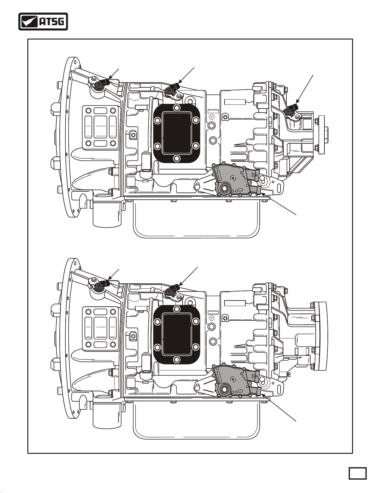
Technical Service Information
ALLISON 1000/2000 SERIES
Engine Speed
Sensor
Turbine Speed
Sensor
AllisonAllison
Output Speed
Sensor
Neutral Start
Switch
Engine Speed
Sensor
TWO WHEEL DRIVE
Turbine Speed
Sensor
AllisonAllison
Neutral Start
Switch
FOUR WHEEL DRIVE
Figure 1
AUTOMATIC TRANSMISSION SERVICE GROUP
Copyright © 2000 ATSG
3
Page 4
Technical Service Information
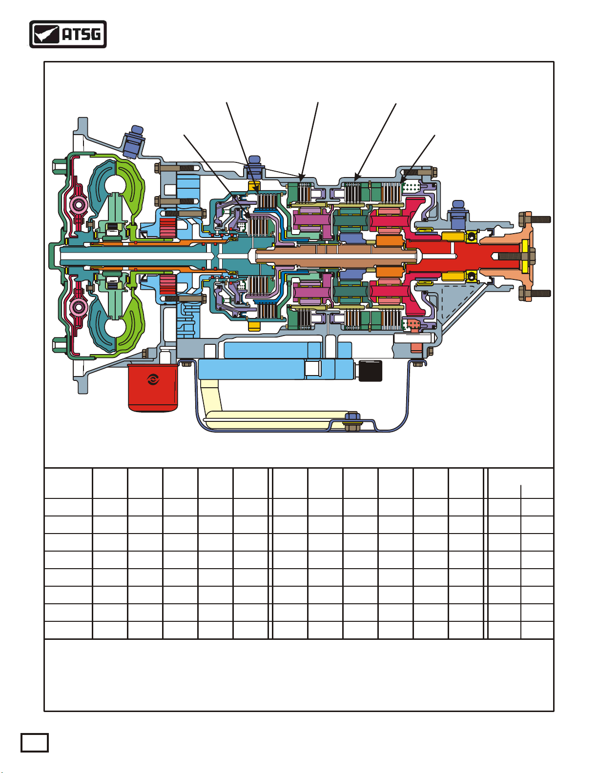
ALLISON 1000/2000 SERIES TRANSMISSION
"C4" CLUTCH "C3" CLUTCH "C2" CLUTCH
"C1" CLUTCH
"C5" CLUTCH
C1
Range
Park
Reverse X
Neutral
OD-1st
OD-2nd
OD-3rd
OD-4th
OD-5th
X = Electrical Power Applied To Solenoid
= Apply Solenoid "F" To Apply Converter Clutch
*
= Solenoids "A" and "B" are "Trim" solenoids used to control oncoming, off-going, and
**
holding pressure to the five clutch packs.
Clut
ON ON
ON
ON ON
4
C2
ClutC3ClutC4ClutC5Clut
ONON
ON
ONON
ON
ON
ON
AUTOMATIC TRANSMISSION SERVICE GROUP
Sol
"A"
**
**
**
**
**
**
**
Figure 2
Sol
"B"
**
**
**
**
**
**
**
**
Sol
"C"
X
X
X
Sol
"D"
XXON
X
X
Sol
"E"
X
X
X
Sol
"F"
*
*
X
X
*
***
Copyright © 2000 ATSG
Ratios
1000 2000
4.49
3.10
1.81
1.41
1.00
0.71
5.09
3.51
1.90
1.44
1.00
0.74
Page 5
Technical Service Information
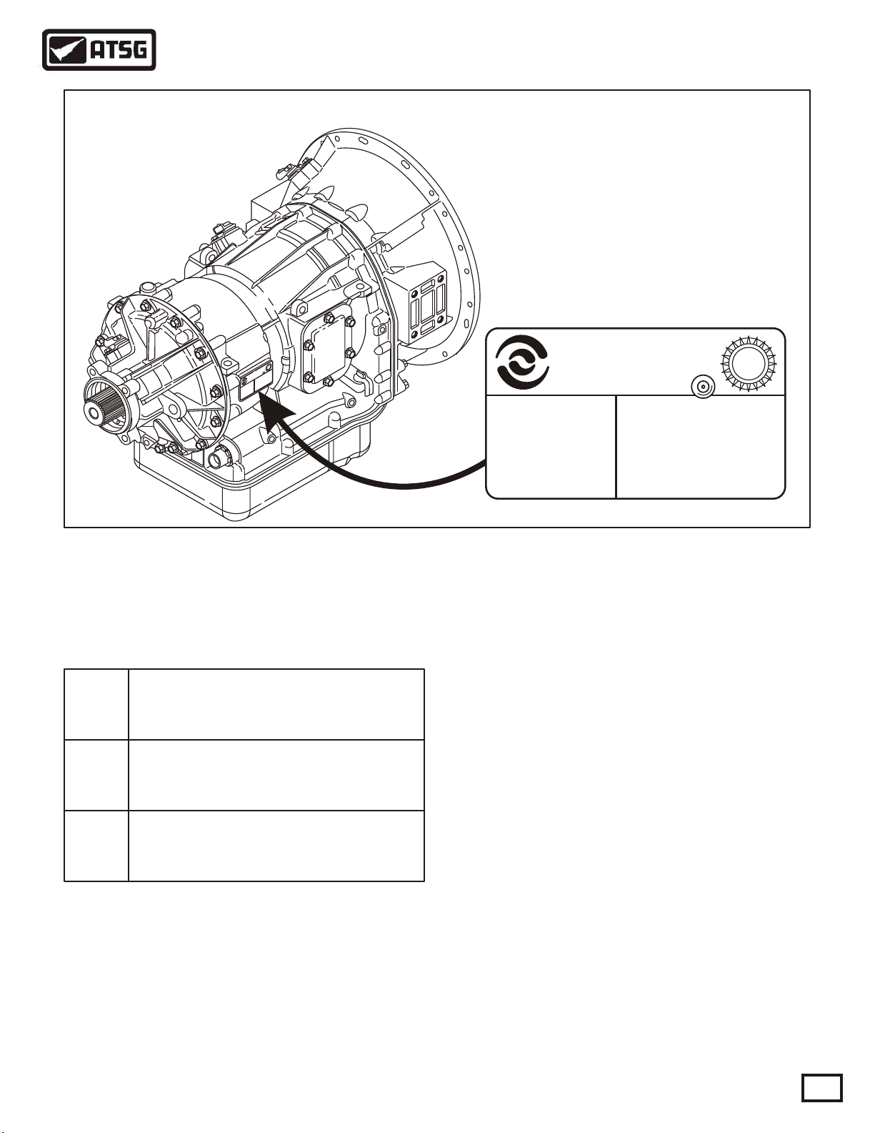
ALLISON IDENTIFICATION TAG LOCATION
9
.8
9
.8
9
.8
9
.8
9
.8
9
.8
9
.8
9
.8
9
9
.8
.8
W
A
U
3
3
9
X
X
n
X
n
.
X
P
o
R
X
-
i
O
X
C
X
s
S
X
R
iso
X
s
O
l
A
i
X
T
l
O
X
AN
-
M
X
L
X
m
X
A
NDI
X
I
A
R
s
X
X
,
X
S
NE
I
X
E
n
L
X
X
G
-
O
X
P
a
X
A
OF
X
X
N
N
r
X
X
X
A
O
I
I
X
X
X
S
T
I
ND
X
V
X
I
-
I
X
D
X
X
X
X
X
X
X
X
X
X
-
X
X
L
X
X
E
X
X
X
D
I
X
OD
T
X
S
M
-
IE
X
X
X
R
X
X
E
X
E
S
T
X
0
-
DA
0
0
.
X
1
X
X
O
X
N
X
L
1
A
2
I
F
X
R
9
X
E
9
S
X
X
N
X
X
X
FC
X
E
X
X
X
X
X
X
X
X
9
.
8
9
.
8
9
.
8
9
.
8
9
.
8
9
.
8
MODEL
1000 SERIES
99F21 X X
SERIAL NO.
X X X X X X X X X X
X X X X X X X X X
Allison
TransmissionTransmission
DIVISION OF GENERAL MOTORS CORP.
INDIANAPOLIS, INDIANA
X X - X X X X X X - X X X X
DATE
EFCN
X X - X X X X X X - X X X X
TID
X X - X X X X X X - X X X X
X X - X X X X X X - X X X X
X X - X X X X X X - X X X X
UAW
933
Figure 3
TRANSMISSION IDENTIFICATION TAG
Several different transmission configurations are
available within the 1000/2000/2400 Series. The
different models are identified as follows:
1000
Series
2000
Series
2400
Series
Each transmission is identified by a model
designation, group numbers, and serial number. This
information is included on the transmission
identification tag located on the right rear side of the
transmission case, as shown in Figure 3.
Heavy-duty automatic transmission
with parking pawl.
Maximum GVW = 19850 lb.
Heavy-duty automatic transmission
without parking pawl.
Maximum GVW = 30000 lb.
Heavy-duty automatic transmission
with parking pawl.
Maximum GVW = 26000 lb.
Copyright © 2000 ATSG
This information must be used when discussing
specific service issues, or when parts replacement is
necessary. The transmission identification tag also
includes the date of manufacture, and also the
transmission identification number used with the
diagnostic systems.
Special Note:
Allison Series 1000/2000/2400 transmissions are
designed and manufactured to metric standards, and
metric tools are required for service.
The cooler ports and the main line pressure tap are
the only non-metric fittings on the transmission
case. The output flange/yoke retaining bolt is also
non-metric.
AUTOMATIC TRANSMISSION SERVICE GROUP
5
Page 6
Technical Service Information
GENERAL DESCRIPTION AND OPERATION
Allison 1000/2000/2400 Series transmissions are
torque converter driven fully automatic units. All
models have neutral, reverse, and up to 5 forward
speeds, with 5th gear being overdrive. Refer to
Figure 2 for the different gears ratios available in the
different models.
The torque converter housings of these units mate
directly to SAE No. 2, SAE No. 3, or direct to the
engine block in some cases. Flexplate drive is used
for all engine to transmission torque transfer.
Several different torque converters are available to
match the transmissions to a wide variety of diesel
and gasoline engines. The torque converter is a single
stage, three element unit, consisting of a pump, stator,
and turbine, with the addition of a converter clutch to
provide direct drive from the engine to the
transmission. The converter clutch is applied and
released electronically, and changes the direction of
fluid flow in the converter as in most typical
converters today.
Internally these units contain 2 rotating clutches (C1
and C2), and 3 brake clutches (C3, C4 and C5), to
direct the flow of torque through the unit. All clutch
packs are hydraulically applied and spring released,
with automatic wear compensation, and their
locations in the transmission are shown in the cutaway in Figure 2.
The Transmission Control Module (TCM) signals
six different solenoids, located on the valve body, to
apply and release clutches based on vehicle speed and
power combinations, and the range selected by the
operator.
The planetary gear train consists of three constant
mesh, helical gear planetary sets, refered to as P1, P2,
and P3. By the engagement of the 5 clutch packs in
various combinations, the planetary gear sets react
singly or together to provide 5 forward speeds,
neutral, and reverse.
A common hydraulic system provides fluid for all
hydraulic operations, lubrication, and cooling. The
front oil pump, driven by the converter, provides the
pressure needed for the hydraulic system, and comes
from the common sump in the bottom pan.
A suction filter, located in the bottom pan provides
general protection to the entire hydraulic system, and
a spin-on filter provides full time protection for the
control solenoids and multipass protection for the
entire system.
The spin-on filter is located externally on the
converter housing at the lower left front of the
transmission.
Some 1000/2000/2400 Series transmissions are
available with an optional extension housing that
accommodates an OEM installed two shoe,
expanding type, drum parking brake.
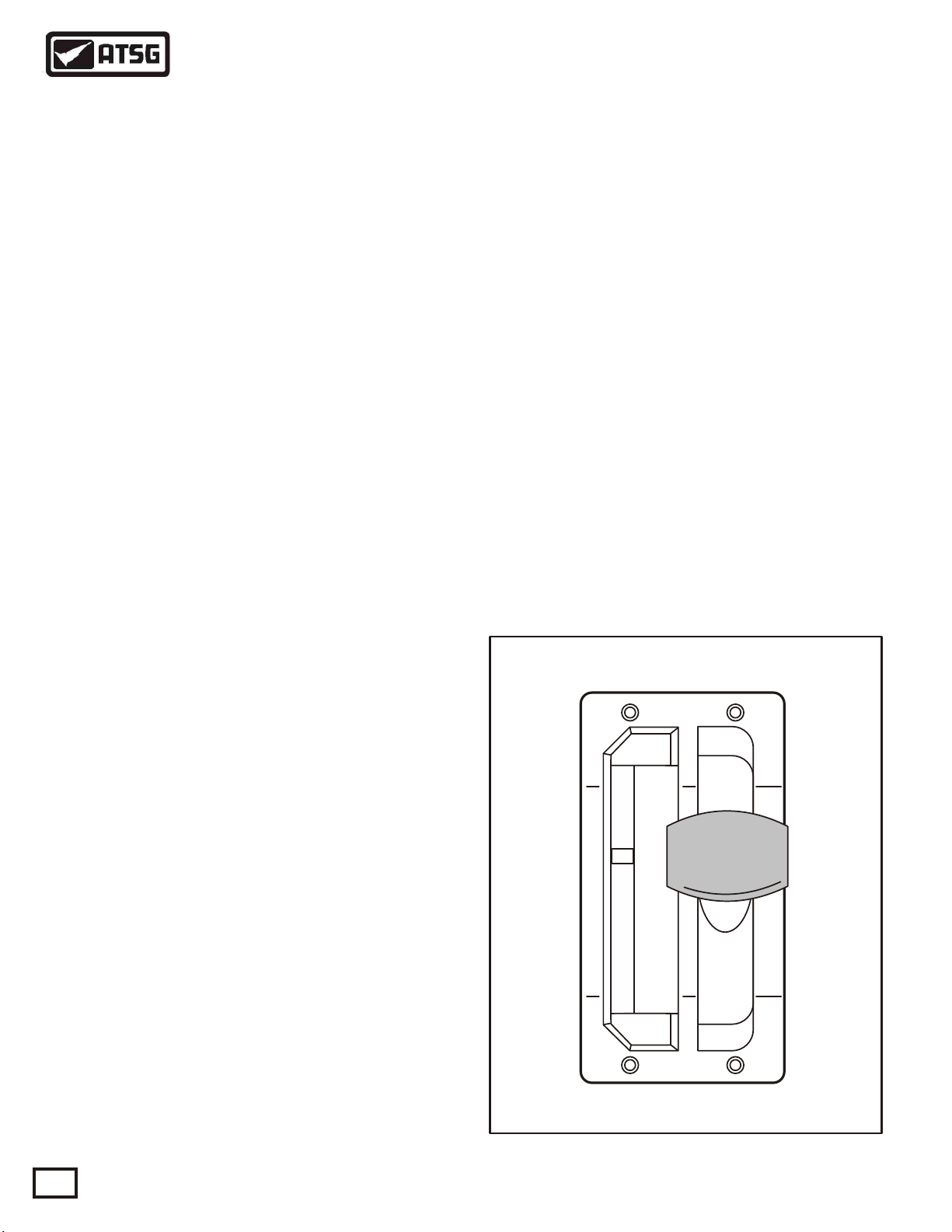
The 1000/2000/2400 Series transmissions use lever
type shift selectors, as shown in Figure 4. The vehicle
may be equipped with one or two shift selectors,
depending on the number of operator stations for
driving the vehicle and/or operating a variety of
chassis mounted equipment. The shift positions on
the shift selector can vary according to the shift
selector installed in the vehicle.
NOTE: Refer to Figure 5 for the various Shift
Selector positions, and corresponding ranges that
can be attained for all 1000/2000/2400 Series
models.
TYPICAL MANUAL SHIFT TOWER
DO NOT
SHIFT
P
R
N
D
4
2
1
DO NOT
SHIFT
Copyright © 2000 ATSG
Figure 4
6
AUTOMATIC TRANSMISSION SERVICE GROUP
Page 7
Technical Service Information
ALL 1000 AND 2400 SERIES
Shift
Selector
Position
P (Park)
R (Reverse)
N (Neutral)
D (Drive)
4 (Fourth)
3 (Third)
1 (First)
* With Park Pawl Engaged
** 4 Speed Calibration or Trailering Mode
Gears
Available
Neutral*
Reverse
Neutral
1-5
1-4
1-3
1st
Selector
Position
P (Park)
R (Reverse)
N (Neutral)
D (Drive)
4 (Fourth)
2 (Second)
1 (First)
ALL 2000 SERIES "WITH" AUTO-APPLY PARKING BRAKE
Shift
Selector
Position
PB = (Park)
R (Reverse)
Gears
Available
Neutral*
Reverse
Selector
Position
PB = (Park)
R (Reverse)
Shift
Shift
Gears
Available
Neutral*
Reverse
Neutral
1-5
1-4
1-2
1st
Gears
Available
Neutral*
Reverse
Shift
Selector
Position
P (Park)
R (Reverse)
N (Neutral)
D (Drive)
3 (Third)
2 (Second)
1 (First)
Shift
Selector
Position
PB = (Park)
R (Reverse)
Gears
Available
Neutral*
Reverse
Neutral
1-5 (1-4)**
1-3
1-2
1st
Gears
Available
Neutral*
Reverse
N (Neutral)
D (Drive)
4 (Fourth)
3 (Third)
1 (First)
* With Auto-Apply Parking Brake Engaged
** 4 Speed Calibration or Trailering Mode
PB = Auto-Apply Parking Brake
Neutral
1-5
1-4
1-3
1st
N (Neutral)
D (Drive)
4 (Fourth)
2 (Second)
1 (First)
ALL 2000 SERIES "WITHOUT" AUTO-APPLY PARKING BRAKE
Shift
Selector
Position
R (Reverse)
N (Neutral)
D (Drive)
4 (Fourth)
3 (Third)
Gears
Available
Reverse
Neutral
1-5
1-4
1-3
Selector
Position
R (Reverse)
N (Neutral)
D (Drive)
4 (Fourth)
2 (Second)
Shift
Neutral
1-5
1-4
1-2
1st
Gears
Available
Reverse
Neutral
1-5
1-4
1-2
N (Neutral)
D (Drive)
3 (Third)
2 (Second)
1 (First)
Shift
Selector
Position
R (Reverse)
N (Neutral)
D (Drive)
3 (Third)
2 (Second)
Neutral
1-5 (1-4)**
1-3
1-2
1st
Gears
Available
Reverse
Neutral
1-5 (1-4)**
1-3
1-2
1 (First)
** 4 Speed Calibration or Trailering Mode
1st
1 (First)
AUTOMATIC TRANSMISSION SERVICE GROUP
Figure 5
1st
1 (First)
1st
Copyright © 2000 ATSG
7
Page 8
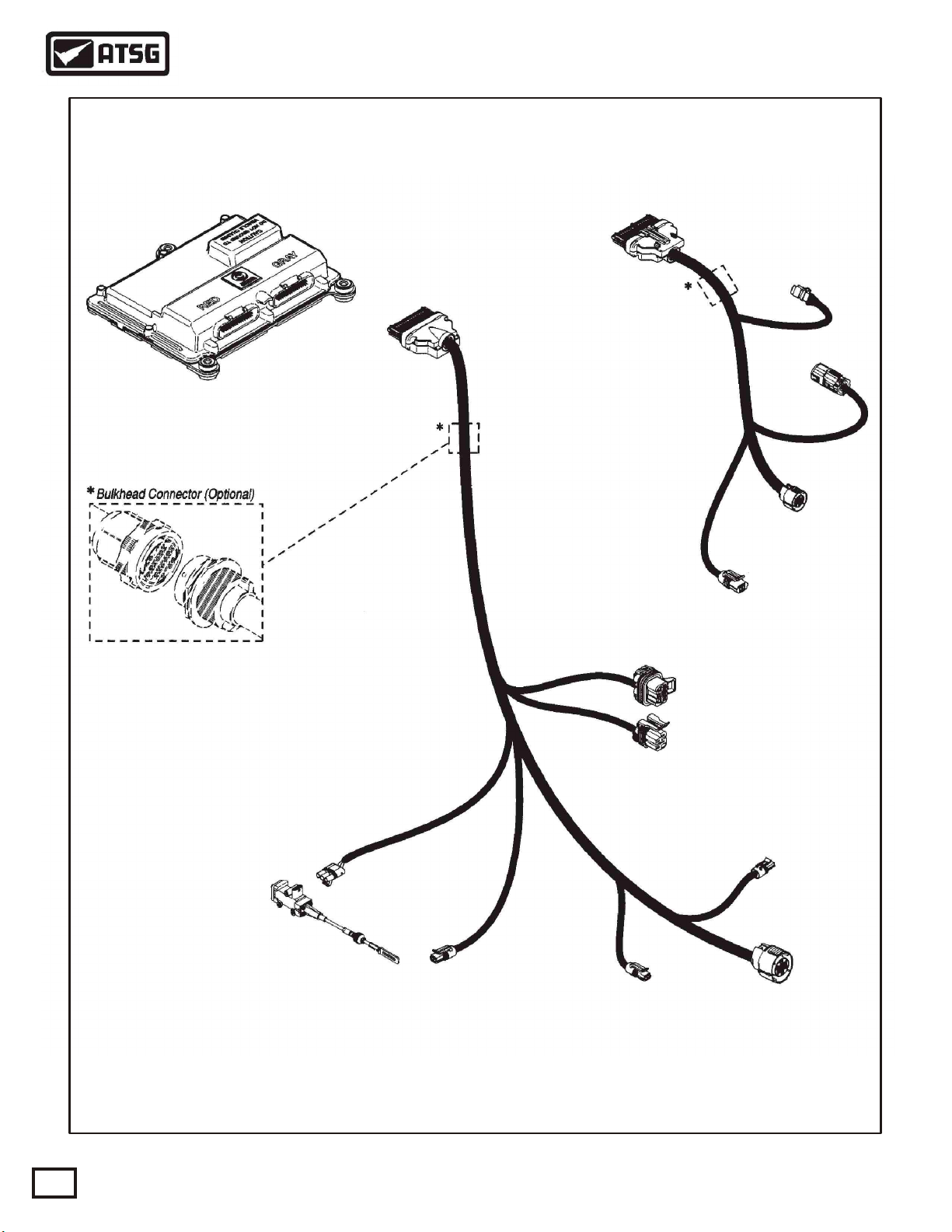
Technical Service Information
TYPICAL TRANSMISSION CONTROL MODULE
AND VEHICLE HARNESS
TRANSMISSION CONTROL
MODULE (TCM)
TRANSMISSION (J2)
HARNESS
"J2"
CONNECTOR
(RED)
"J1"
CONNECTOR
(GRAY)
VEHICLE (J1)
HARNESS
J 1939
CONNECTOR
(OPTIONAL)
VIW "X"
CONNECTOR
VIW "Y"
CONNECTOR
GP 19
CONNECTOR
THROTTLE
POSITION
SENSOR (TPS)
Actual harness configuration may differ from this illustration.
TPS
CONNECTOR
TURBINE
SPEED SENSOR
CONNECTOR
7 PIN
4 PIN
NSBU SWITCH
CONNECTORS
OUTPUT
SPEED SENSOR
CONNECTOR
ENGINE
SPEED SENSOR
CONNECTOR
Copyright © 2000 ATSG
Figure 6
8
AUTOMATIC TRANSMISSION SERVICE GROUP
Page 9
Technical Service Information
ELECTRICAL OPERATION
The electronic control of the transmission is
performed by the Transmission Control Module
(TCM). Transmissin Control Modules are available
in both 12V and 24V configurations, to match the
configuration of the vehicle electrical system.
The TCM, shown in Figure 6, recieves and processes
signals from various switches and sensors. The TCM
determines shift sequences, shift timing, and clutch
apply and release pressures. The TCM uses this
information to control solenoids and valves, supply
system status, and provide diagnostic information for
service technicians.
EXTERNAL COMPONENTS
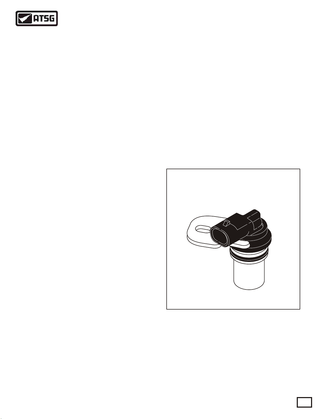
SPEED SENSORS
The speed sensors are variable reluctance devices
which convert mechanical motion to an AC voltage.
Each sensor consists of a wire coil wrapped around a
pole piece that is adjacent to a permanent magnet.
These elements are contained in a housing which is
mounted adjacent to a rotating ferrous member, such
as a gear tooth. Two signal wires extend from one end
of the housing and an exposed end of the pole piece is
at the opposite end of the housing. As a ferrous object,
such as a gear tooth approaches and passes through
the gap at the end of the pole piece, an AC voltage
pulse is induced in the wire coil. The TCM calculates
the frequency of these AC pulses and converts it to a
speed value. The AC voltage generated varies from
150mV at low speed to 15V at high speed. The signal
wires from the sensor are formed as twisted pairs to
cancel magnetically induced fields. The cable is also
shielded to protect from voltage-related fields. The
typical speed sensor is shown in Figure 7. Noise from
other sources is eliminated by using two-wire
differential inputs at the TCM.
ENGINE SPEED SENSOR
The Engine Speed Sensor is externally mounted in
the torque converter housing, and directed at the ribs
protruding from the torque converter as shown in
Figure 1.
TURBINE SPEED SENSOR
The Turbine Speed Sensor is externally mounted in
the main transmission case, and directed at the tone
wheel or PTO drive gear attached to the C1/C2 clutch
housing as shown in Figure 1.
OUTPUT SPEED SENSOR
The Output Speed Sensor is externally mounted in
the extension housing and directed at the teeth of a
tone wheel splined to and rotating with the output
shaft as shown in Figure 1.
TYPICAL SPEED SENSOR
Copyright © 2000 ATSG
Figure 7
AUTOMATIC TRANSMISSION SERVICE GROUP
9
Page 10
Technical Service Information
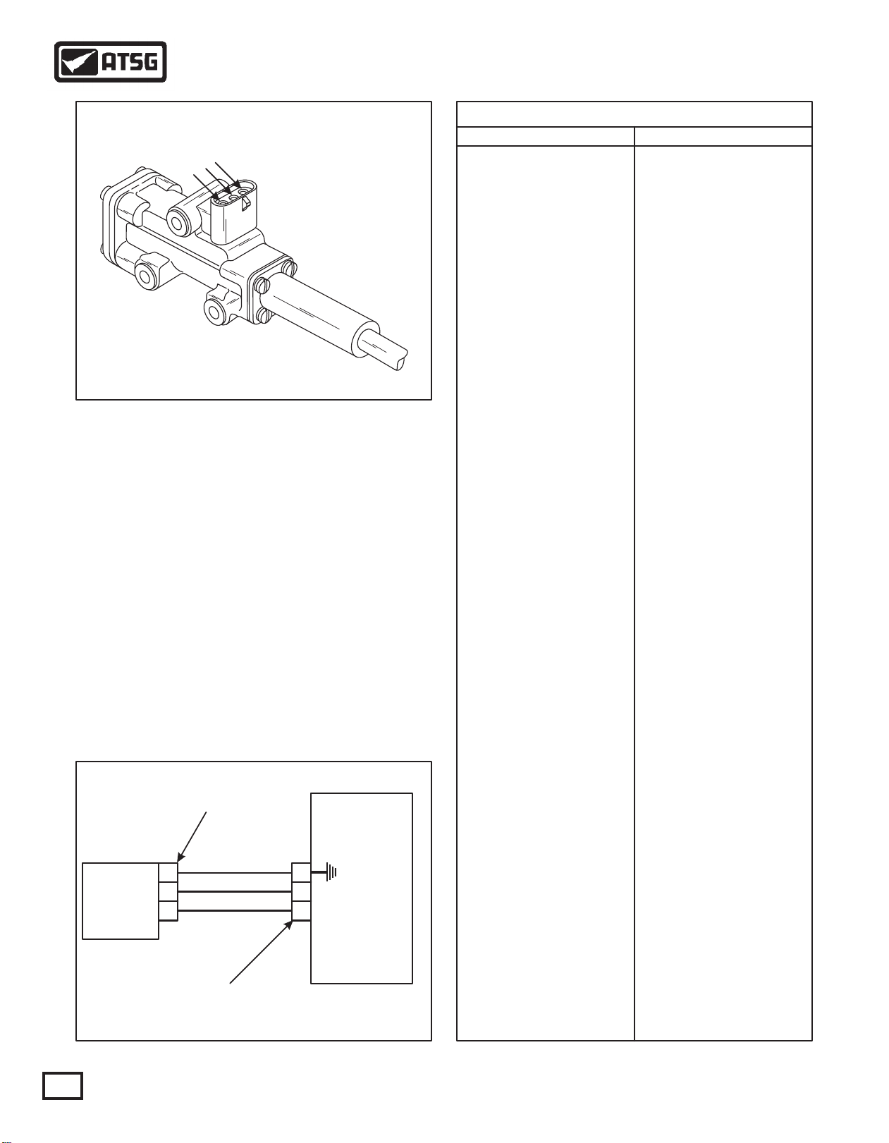
THROTTLE POSITION SENSOR
C
B
A
Copyright © 2000 ATSG
Figure 8
THROTTLE POSITION SENSOR
The Throttle Position Sensor (TPS) can be mounted to
the engine, chassis, or transmission. The TPS
contains a pull actuation cable and a potentiometer.
One end of the cable is attached to the throttle lever
and the other end, inside a protective housing, to the
potentiometer. Output voltage from the TPS is
directed to the Transmission Control Module (TCM)
through the external harness. The voltage signal will
vary and indicates the throttle position and in
combination with other input data will determine shift
timing. Refer to the chart provided in Figure 10 for
approximate voltages at various throttle openings. It
is basically the same as most current GM models with
0.5 volts at idle, to 5.0 volts at wide open throttle.
TPS
Throttle
Position
Sensor
(TPS)
Connector
Green, Ground
A
Blue, Signal Ret.
B
Pink, 5V Supply
C
TCM "J2" (RED)
Connector
Transmission
Control Module
(TCM)
20
9
19
(TPS) Distance of Travel Versus Volts
mm/inch
0/0
1/.039"
2/.079"
3/.118"
4/.157"
5/.197"
6/.236"
7/.275"
8/.314"
9/.354"
10/.394"
11/.433"
12/.472"
13/.511"
14/.551"
15/.590"
16/.629"
17/.669"
18/.708"
19/.748"
20/.787"
21/.826"
22/.866"
23/.905"
24/.945"
25/.984"
26/1.023"
27/1.063"
28/1.102"
29/1.142"
30/1.181"
31/1.220"
32/1.260"
33/1.299"
34/1.339"
35/1.378"
36/1.417"
37/1.457"
38/1.496"
39/1.535"
40/1.575"
41/1.614"
42/1.654"
43/1.693"
44/1.732"
45/1.772"
46/1.811"
Volts
0
0.11
0.22
0.33
0.44
0.55
0.66
0.77
0.88
0.99
1.10
1.20
1.30
1.43
1.54
1.65
1.76
1.87
1.98
2.08
2.19
2.30
2.41
2.52
2.63
2.74
2.85
2.96
3.07
3.18
3.29
3.40
3.51
3.62
3.73
3.84
3.95
4.06
4.17
4.28
4.39
4.50
4.61
4.72
4.83
4.94
5.05
10
Figure 10Figure 9
AUTOMATIC TRANSMISSION SERVICE GROUP
Page 11
Technical Service Information
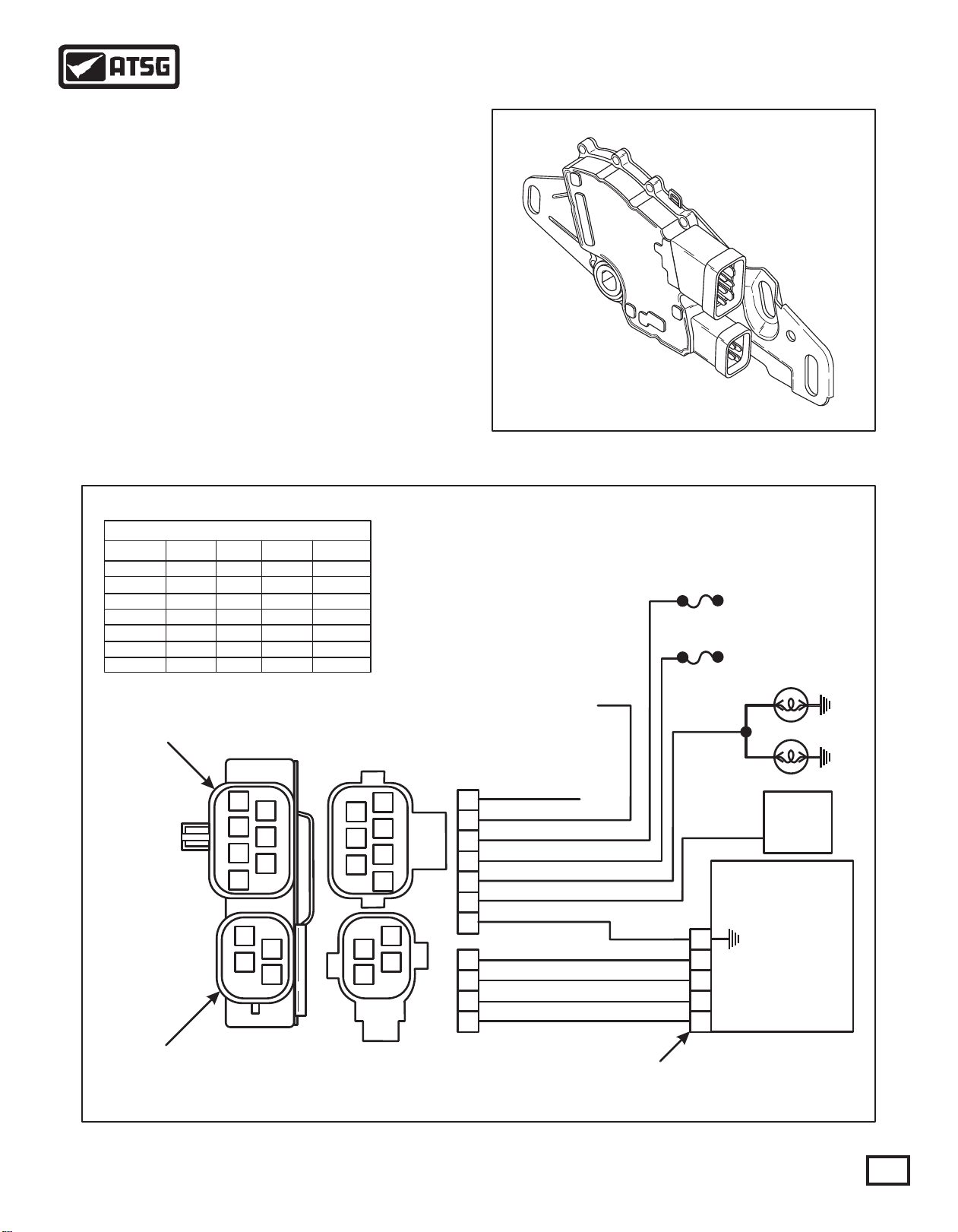
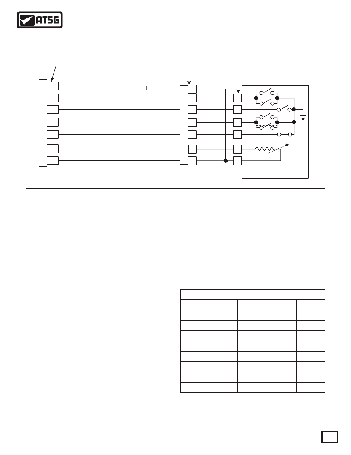
NEUTRAL START BACK-UP SWITCH
The installation of a transmission mounted Neutral
Start/ Reverse Signal switch is required. This switch
commonly refered to as an "NSBU Switch", mounts
directly onto the transmission case from the outside
and detects the angular position of the manual shift
selector shaft. This position is relayed to the TCM so
that certain vehicle control functions can be
coordinated with the position of the shift controls.
The NSBU Switch has redundant circuitry to alert the
TCM in the event of a single wire or switch failure.
The switch is interfaced to the starter circuit, and the
reverse signal provision may be used to activate
vehicle back-up lights and/or reverse warning
devices.
Refer to Figures 11 and 12.
NSBU SWITCH WIRE SCHEMATIC
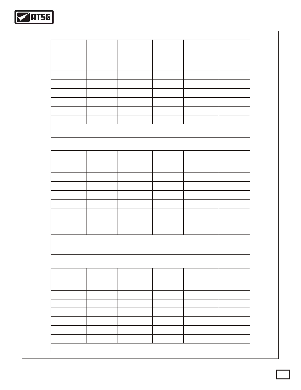
NSBU SWITCH RANGE CHART ON SCAN TOOL
Range A B C P
P
R
N
D
3
2
1
OFF
OFF
ON
ON
OFF
OFF
ON
ON ON
OFF
OFF
OFF
OFF
ON
ON
ON
ON
OFF
OFF
OFF
OFF
OFF
ON
OFF
ON
OFF
ON
OFF
NEUTRAL START BACK-UP SWITCH
Copyright © 2000 ATSG
Figure 11
Rev/Park Accessory
Battery Feed
PK/NEUT Start
Battery Feed
7-Way NSBU
Switch Receptacle
(Face View)
4-Way NSBU
Switch Receptacle
(Face View)
Park Accessory
Back-up Lamps
Not Used
A
G
B
F
C
E
D
C
A
D
B
Harness Connectors
A
G
B
F
C
E
D
C
A
D
B
NSBU Switch
(Face View)
A
B
C
E
F
G
D
A
B
C
D
Tan
Blue
Yellow
Pink
Orange
Green
Blue
Gray
White
Yellow
TCM "J2" (RED)
Connector
20
5
7
8
6
Copyright © 2000 ATSG
Starter
Relay
Transmission
Control Module
(TCM)
Figure 12
AUTOMATIC TRANSMISSION SERVICE GROUP
11
Page 12
TCM "J2" (Red)
Receptacle
Technical Service Information
RED
RED
R
R
ED
ED
G
G
GR
GR
R
R
A
A
A
A
Y
Y
Y
Y
TCM "J1" (Gray)
Receptacle
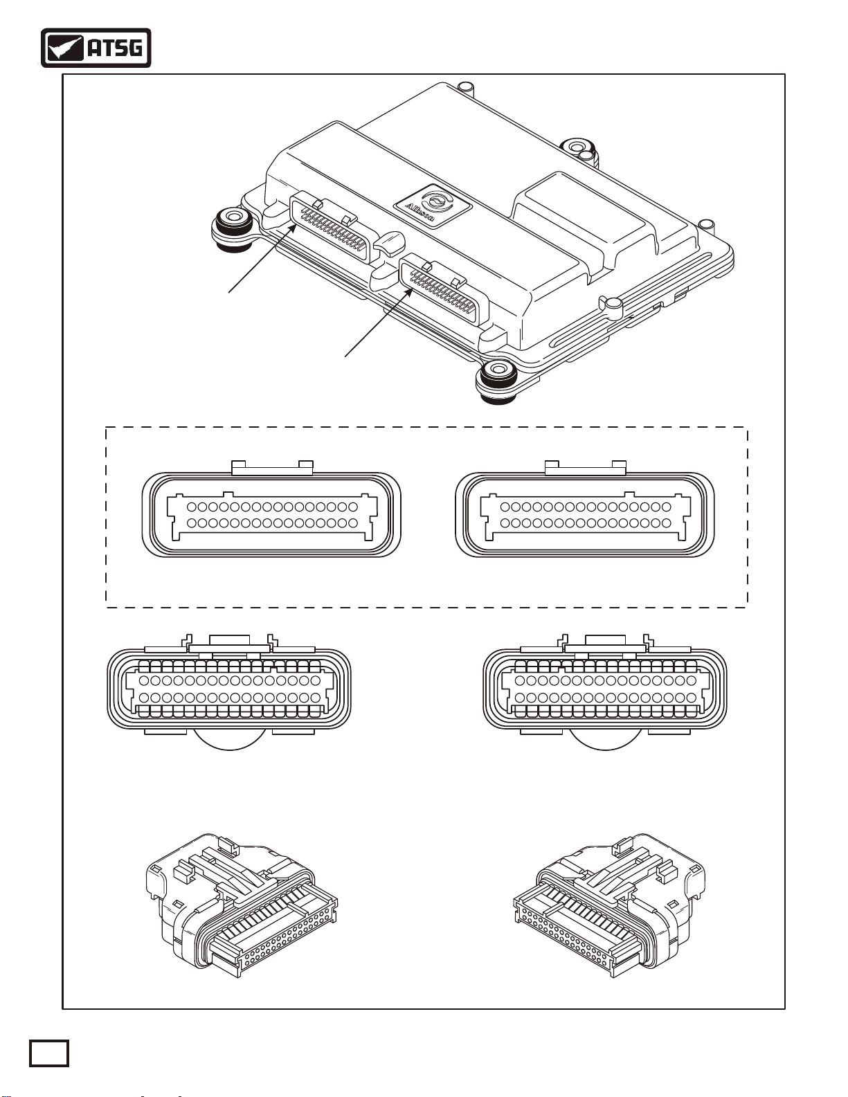
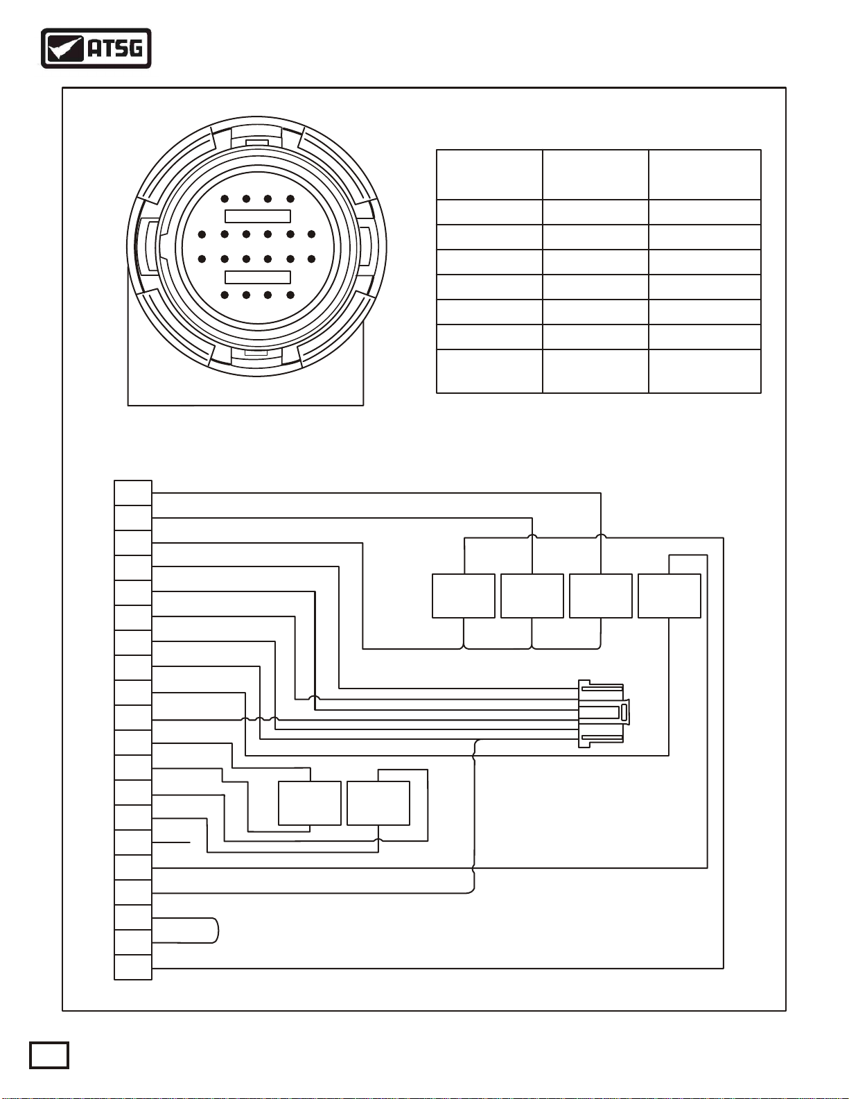
TRANSMISSION CONTROL MODULE (TCM)
S
S
IS
IS
TO
TO
SSI
SSI
D TO
D TO
N
N
ND
ND
U
U
CHASS
CHASS
U
U
CHA
CHA
E
E
O
O
E
E
N
N
N
N
L
L
R
R
RO
RO
C
C
ICL
ICL
I
I
IO
IO
H
H
T G
T G
T
T
TIO
TIO
EH
EH
O
O
U
U
OT G
OT G
VE
VE
V
V
N
N
A
A
AU
AU
N
N
O
O
O
O
C
C
C
C
D
D
D
D
1322313304295286278251023122114
TCM "J2" (Red)
Receptacle
14
13
151816
19
20
17
9
11
25
23
21
24
22
10
12
TCM "J2" (Red)
Harness Connector
(Face View)
72692411221320151816
7
26
1322313304295286278
1322313304295286278251023122114
19
17
72692411221320151816
19
17
TCM "J1" (Gray)
Receptacle
14
11
13
151816
21
19
22
20
17
7269
25
23
24
10
12
1322313304295286278
TCM "J1" (Gray)
Harness Connector
(Face View)
12
Copyright © 2000 ATSG
Figure 13
AUTOMATIC TRANSMISSION SERVICE GROUP
Page 13
Technical Service Information
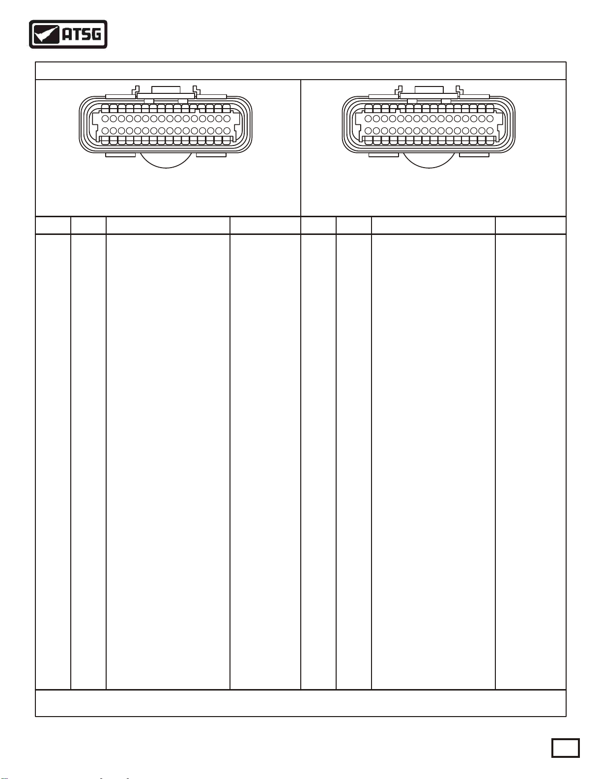
TCM CONNECTOR PIN IDENTIFICATION CHART
14
11
13
151816
21
19
22
20
17
7269
25
23
24
10
12
TCM "J2" (Red)
Harness Connector
(Face View)
Term. Term.Color ColorCircuit Ends Circuit Ends
Blue Trans-D Vehicle System
1 1
2 2
Pink
3 3
White
4 4
Green
Blue
5 5
Yellow
6 6
Gray
7 7
White
8 8
Blue
9 9
10 10
Orange
11 11
12 12
13 13
14 14
15 15
16 16
17 17
18 18
19 19
20 20
21
22
23
24
25
26
27
28
29
30
31
32
Blue
Orange
Blue
Yellow
Green
Orange
Pink
Green
Yellow
Yellow
White
Pink
Orange
Green
Blue
Gray
White
Orange
Green
Circuit Function Circuit Function
PSA Input Battery Ground
PSA Input
PSA Input
PSA Input
NSBU Input
NSBU Input
NSBU Input
NSBU Input
Throttle Position Sensor
Tan
Tan
Tan
Trans Sump Temp Input
Retarder Temp Input (Opt)
Engine Coolant Temp
Turbine Speed Sensor (High)
Turbine Speed Sensor (Low)
Output Speed Sensor (High)
Output Speed Sensor (Low)
Engine Speed Sensor (High)
Engine Speed Sensor (Low)
TPS Voltage Supply
Analog Ground
TRANS ID
Trim Solenoid A (High)
Trim Solenoid A (Low)
Trim Solenoid B (High)
Trim Solenoid B (Low)
C Solenoid Ground (On/Off)
D Solenoid Ground (On/Off)
E Solenoid Ground (On/Off)
F Solenoid Low (PWM)
G Solenoid Low (PWM)(Opt)
C, D, E Solenoid V Supply
F Solenoid High (PWM)
1322313304295286278
Trans-F
Trans-E
Trans-K
NSBU-4A
NSBU-4D
NSBU-4B
NSBU-4C
TPS-B
Trans-G
R Temp-A
ECTS-A
TSS-A
TSS-B
OSS-A
OSS-B
ESS-A
ESS-B
TPS-C
Trans-H, ECTS-A,
Temp-B, NSBU-7D
R-Temp-B, TPS-A
Trans-T
Trans-L
Trans-M
Trans-N
Trans-P
Trans-A
Trans-B
Trans-W
Trans-J
Trans-J
Trans-C
Trans-S
21
22
23
24
25
26
27
28
29
30
31
32
Gray
Yellow
Pink
Yellow
Gray
Blue
Orange
Green
White
Yellow
Green
Blue
Pink
Orange
Yellow
White
Pink
Green
Tan
Orange
White
Blue
Pink
White
Green
Tan
Pink
Yellow
Red
Blue
Green
Black
14
11
13
151816
21
19
22
20
17
7269
25
23
24
10
12
TCM "J1" (Gray)
Harness Connector
(Face View)
Ignition Power
Battery Power
Ignition Power
Battery Ground
GPI 1
GPI 2
GPI 3
GPI 4
GPI 5
GPI 6
GPI 7
GPI 8
GPI 9
Retarder Mod. Reg. (Opt)
PWM Throttle
Sensor Power
Analog Ground
GPO 1
GPO 2
GPO 3
GPO 4
Range Inhibit Indicator
GPO 6
CHECK TRANS
Vehicle Speed
Vehicle Speed
Digital Ground
CAN High
ISO 9141
CAN Shield
CAN Low
1322313304295286278
Vehicle System
Vehicle System
Vehicle System
Vehicle System
Vehicle System
Vehicle System
Vehicle System
Vehicle System
Vehicle System
Vehicle System
Vehicle System
Vehicle System
Vehicle System
RMR-B
Vehicle System
RMR-C
RMR-A
Vehicle System
Vehicle System
Vehicle System
Vehicle System
Vehicle System
Vehicle System
Vehicle System
Vehicle System
Vehicle System
Vehicle System
J 1939 A or H
Vehicle System
J 1939 C or S
J 1939 B or L
Figure 14
AUTOMATIC TRANSMISSION SERVICE GROUP
Copyright © 2000 ATSG
13
Page 14

DTC Description
Technical Service Information
DIAGNOSTIC TROUBLE CODE (DTC) CHART
"Check Trans"
Light
P0117
P0118
P0121
P0122
P0123
P0218
P0561
P0562
P0563
P0602
P0606
P0700
P0703
P0705
P0706
P0708
P0711
P0712
P0713
P0716
P0717
P0721
P0722
P0726
P0727
P0731
P0732
P0733
P0734
P0735
P0736
P0741
P0742
P0746
P0747 YES
P0763
P0768
P0776 YES
P0777 YES
Engine Coolant Temperature Circuit Low Voltage (High Temperature)
Engine Coolant Temperature Circuit High Voltage (Low Temperature)
Throttle Position Sensor Performance Problem
Throttle Position Sensor Circuit Low Voltage
Throttle Position Sensor Circuit High Voltage
Transmission Fluid Over Temperature
Urealistic variations in vehicle system voltage
System Voltage Low
System Voltage High
TCM Not Programmed
Transmission Control Module Internal Performance
MIL Illumination requested
Brake Switch Circuit
Transmission Range Sensor Circuit (PRNDL Input)
Transmission Range Sensor Circuit Performance
Transmission Range Sensor Circuit High Input
Transmission Fluid Temperature Circuit Performance
Transmission Fluid Temperature Circuit Low Voltage (High Temperature)
Transmission Fluid Temperature Circuit High Voltage (Low Temperature)
Turbine Speed Sensor Circuit Performance
Turbine Speed Sensor Circuit No Signal
Output Speed Sensor Circuit Performance
Output Speed Sensor Circuit No Signal
Engine Speed Sensor Circuit Performance
Engine Speed Sensor Circuit No Signal
Incorrect 1st Gear Ratio
Incorrect 2nd Gear Ratio
Incorrect 3rd Gear Ratio
Incorrect 4th Gear Ratio
Incorrect 5th Gear Ratio
Incorrect Reverse Gear Ratio
Torque Converter Clutch System Stuck Off
Torque Converter Clutch System Stuck On
Torque Converter Clutch Solenoid ElectricalP0742 YES
Solenoid A controlled Clutch Stuck Off
Solenoid A controlled Clutch Stuck On
Pressure Control Trim Solenoid "A" ElectricalP0748 YES
Shift Solenoid "C" Electrical
Shift Solenoid "D" Electrical
Shift Solenoid "E" ElectricalP0773 YES
Solenoid B controlled Clutch Stuck Off
Solenoid B controlled Clutch Stuck On
NO
NO
NO
NO
NO
NO
YES
YES
YES
YES
NO
YES
YES
YES
YES
YES
YES
YES
YES
YES
YES
YES
YES
YES
YES
YES
YES
YES
YES
YES
YES
YES
YES
YES
YES
YES
14
Figure 15
AUTOMATIC TRANSMISSION SERVICE GROUP
Copyright © 2000 ATSG
Page 15

DTC Description
Technical Service Information
DIAGNOSTIC TROUBLE CODE (DTC) CHART
"Check Trans"
Light
P0778
P0836
P0840
P0841
P0842
P0843
P0845
P0846
P0847
P0848
P1688
P1709
P1710
P1711
P1712
P1713
P1714
P1715
P1716
P1720
P1721
P1723
P1724
P1726
P1727
P1760
P1835
P1860
P1891
Pressure Control Trim Solenoid "B" Electrical
4 Wheel Drive Low Switch Circuit Malfunction (may also be listed as P1875)
Transmission Pressure Switch, Solenoid C Circuit
Transmission Pressure Switch, Solenoid C Circuit Stuck Open
Transmission Pressure Switch, Solenoid C Circuit Stuck Closed
Transmission Pressure Switch, Solenoid C Circuit High
Transmission Pressure Switch, Solenoid D Circuit
Transmission Pressure Switch, Solenoid D Circuit Stuck Open
Transmission Pressure Switch, Solenoid D Circuit Stuck Closed
Transmission Pressure Switch, Solenoid D Circuit High
Transmission Pressure Switch, Solenoid E Circuit HighP0870 YES
Transmission Pressure Switch, Solenoid E Circuit Stuck OpenP0871 YES
Transmission Pressure Switch, Solenoid E Circuit Stuck ClosedP0872 YES
Transmission Pressure Switch, Solenoid E Circuit HighP0873 YES
Reverse Pressure Switch MalfunctionP0875 YES
Reverse Pressure Switch Circuit Stuck OpenP0876 YES
TCM Power Input SignalP0880 YES
Unmanaged Engine Torque Delivered To TCM
Transmission Pressure Switch, Solenoid E Circuit
Transmission Pressure Switch, Solenoid E Circuit Stuck Open
Transmission Pressure Switch, Solenoid E Circuit Stuck Closed
Transmission Pressure Switch, Solenoid E Circuit High
Transmission Pressure Switch, Reverse Circuit
Transmission Pressure Switch, Reverse Circuit Stuck Open
Transmission Pressure Switch, Reverse Circuit Stuck Closed
Transmission Pressure Switch, Reverse Circuit High
Trim Solenoid "A" Controlled Clutch Not Engaged
Trim Solenoid "B" Controlled Clutch Not Engaged
Trim Solenoid "A" Controlled Clutch Not Engaged
Trim Solenoid "B" Controlled Clutch Not Engaged
Shift Solenoid "D" Controlled Clutch Not Engaged
Shift Solenoid "E" Controlled Clutch Not Engaged
TCM Supply Voltage
Engine Torque Delivered to TCMP1779 NO
Kickdown Circuit
TCC (PWM) Solenoid Circuit-Electrical
Throttle Position Sensor Clutch PWM Signal Low Input
YES
YES
YES
YES
YES
YES
YES
YES
YES
YES
YES
YES
YES
YES
YES
YES
YES
YES
YES
YES
YES
YES
YES
YES
YES
NO
YES
YES
NO
P1892
U1016
U1300
U1301
U2105
Throttle Position Sensor Clutch PWM Signal High Input
Class 2 Powertrain Controller State Of Health
Serial Data Communication Link Low (Class 2)
Serial Data Communication Link High (Class 2)
CAN Bus Error ECM
Figure 16
AUTOMATIC TRANSMISSION SERVICE GROUP
NO
NO
NO
NO
NO
Copyright © 2000 ATSG
15
Page 16
Technical Service Information
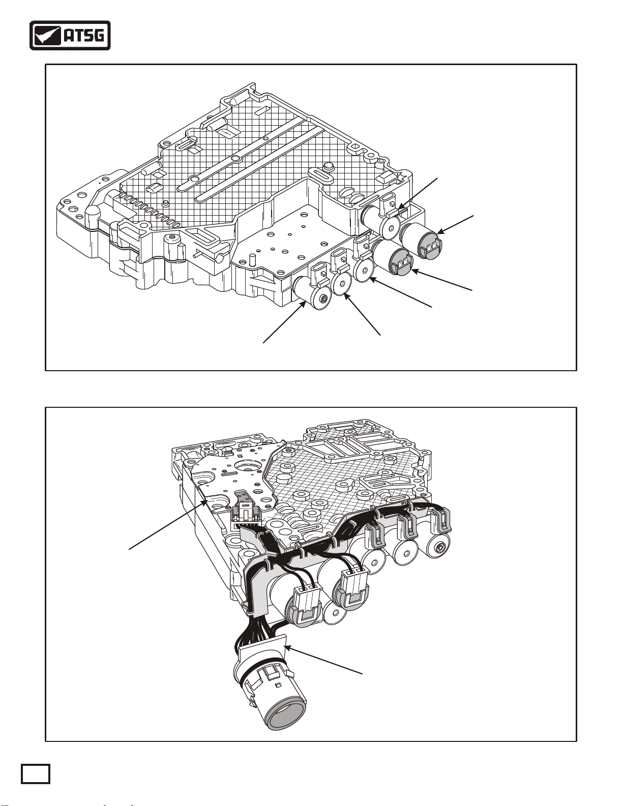
SOLENOID LOCATIONS
Shift Solenoid "E"
(Normally Closed)
Shift Solenoid "C"
(Normally Closed)
Trim Solenoid "A"
(Normally Closed)
Trim Solenoid "B"
(Normally Open)
PRESSURE SWITCH
ASSEMBLY
TCC (PWM) Solenoid "F"
(Normally Closed)
Figure 17
Shift Solenoid "D"
(Normally Closed)
Copyright © 2000 ATSG
16
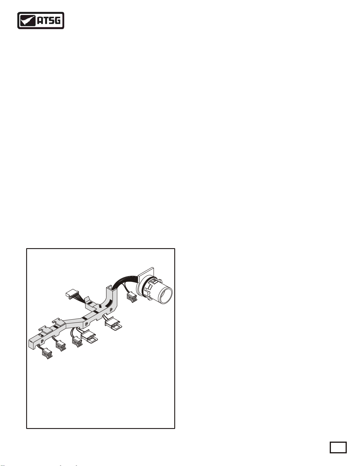
Internal Wiring Harness And
Case Connector Assembly
Copyright © 2000 ATSG
Figure 18
AUTOMATIC TRANSMISSION SERVICE GROUP
Page 17
Technical Service Information
INTERNAL COMPONENTS
Several components of the 1000/2000/2400 Series
electrical control system are located inside of the
transmission as part of the main control valve body.
These components include three different types of
solenoids for controlling the hydraulic action of the
valves in the valve body, and the pressure switch
assembly. An internal wiring harness and case
connector assembly links the internal components
with the Transmission Control Module.
SOLENOIDS
The 1000/2000/2400 Series solenoid locations are
shown in Figure 17. The solenoids may be normally
closed or normally open. A normally closed solenoid
remains closed until a signal from the TCM energizes
the solenoid. A normally open solenoid remains open
until the TCM energizes the solenoid.
TCC (PWM) Solenoid F - This solenoid a normally
closed, pulse width modulated, and operates at a
frequency of 100 Hz (cycles per second) during a
shift. The percentage of time the voltage is ON
during each 100th of a second is called the solenoid
duty cycle.
INTERNAL WIRING HARNESS ASSEMBLY
A 100 percent duty cycle indicates a maximum signal
to the solenoid. A zero percent duty signal indicates a
minimum or no signal to the solenoid. The TCM,
using pulse width modulation programming, varies
the percentage of voltage ON time during a cycle. As
the pulse width, or duty cycle is increased, the
solenoid is ON longer.
Shift Solenoids C, D, E - Shift Solenoids C, D, & E
are normally closed solenoids that provide the
necessary logic to distribute fluid to the correct clutch
packs in the transmission. The shift solenoids provide
either full control line pressure, or exhaust, to the
lands of each of the corresponding Shift V alves C, D,
and E. Shift Solenoids C, D, and E may operate in the
open or closed state with no modulation capability at
all.
Trim Solenoids A and B - Trim Solenoid A and B are
used to control oncoming, off-going, and holding
pressure to the five clutch packs. These solenoids are
reffered to as Pressure Proportional to Current (PPC)
solenoids, since the output hydraulic pressure
supplied by these solenoids is proportional to the
current commanded. Trim Solenoids A and B operate
using a frequency of 1000 Hz. The current causes a
force on the armature and shaft assembly, which is
balanced by fluid pressure acting on the end of the
shaft. The trim solenoids operate using battery
voltage. Trim Solenoid A is a Normally Closed
solenoid, providing 86 psi (590 kpa) at zero current,
and no trim pressure at full current. Trim Solenoid A
allows for limp-home capability in the event of a
power or TCM failure. Trim Solenoid B is a
Normally Open solenoid, and prrovides zero pressure
at zero current.
Serviced as an assembly under
Allison Part Number 15321154.
Copyright © 2000 ATSG
Figure 19
AUTOMATIC TRANSMISSION SERVICE GROUP
INTERNAL WIRING HARNESS
The Internal Wiring Harness Assembly connects the
shift solenoids, clutch trim solenoids, torque
converter clutch solenoid, pressure switch assembly
and temperature sensor to the external harness that
leads to the Transmission Control Module. Refer to
Figure 18 and 19. Figure 20 on Page 18 gives you an
internal wire schematic for all of the internal
components, and pin identification for the external
transmission case connector
Continued on Page 18.
17
Page 18
Technical Service Information
INTERNAL WIRING SCHEMATIC
A
B
M
G
F
N
T
UCV
E
L
D
HPJRK
S
W
PED 4
TRANSMISSION EXTERNAL
CONNECTOR FACE VIEW
Dark Green
A
Orange/Black
B
Pink
C
Light Green
D
Red
E
Blue
F
Orange
G
Black
H
Brown
J
Tan
K
Red/Black
L
Light Blue
M
N
P
R
S
T
U
V
W
Gray
Purple
N/A
Black
Tan
Green
Green
Black/Tan
TRIM (N/C)
SOLENOID
"A"
TRIM (N/0)
SOLENOID
"B"
Solenoid Terminals
Resistance In
Ohms @ 72°F
TRIM "A" 5.5 - 8.0 W
TRIM "B"
SHIFT "C"
SHIFT "D"
SHIFT "E"
TCC "F"
TEMP
SENSOR
SHIFT
SOLENOID
"E"
SHIFT
SOLENOID
"D"
L and M
N and P
C and A
C and B
C and W
J and S
H and G
SHIFT
SOLENOID
"C"
To Pressure
Switch Assembly
5.5 - 8.0 W
TCC
SOLENOID
"F"
A
B
C
D
E
F
20 -30 W
20 -30 W
20 -30 W
8 - 15 W
2.8K W
@ 72° F
18
Copyright © 2000 ATSG
Figure 20
AUTOMATIC TRANSMISSION SERVICE GROUP
Page 19
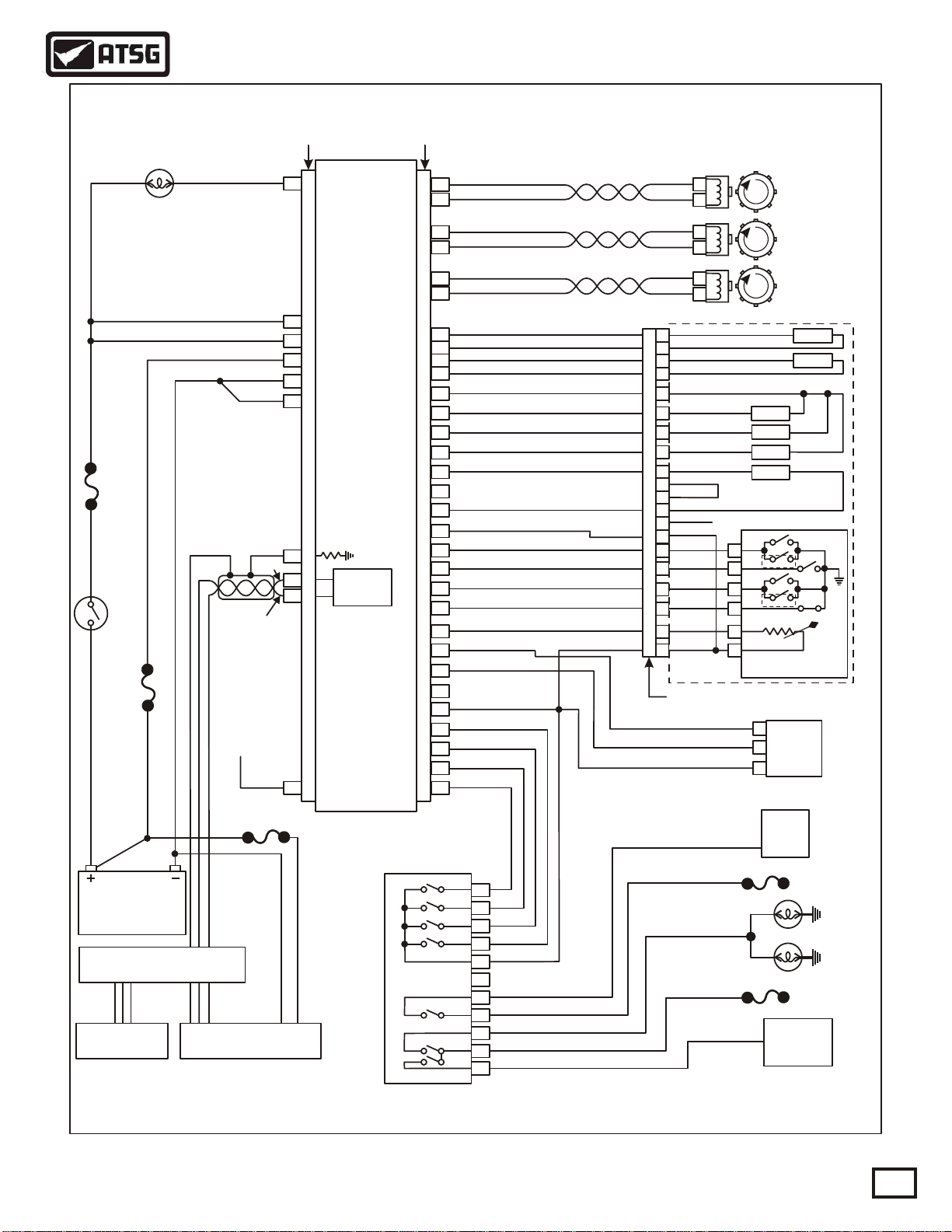
Technical Service Information
See Pages 12 and 13 For
TCM Connector Pin I.D.
CHECK TRANS
CHECK TRANS
LIGHT
LIGHT
IGNITION POWER
IGNITION POWER
BATTERY POWER
TCM GROUND
10A
IGNITION
IGNITION
SWITCH
SWITCH
10A
OPTIONAL SPEEDO
SIGNAL RETURN
TCM "J1" (Gray)
TCM "J1" (Gray)
Yellow
Yellow
Pink
Gray
Gray
Green
Red
Black
Green
CONNECTOR
CONNECTOR
25
CONTROL MODULE
CONTROL MODULE
2
4
3
1
5
GRAYGRAY
31
+
29
_
32
DO NOT GROUND TO
DO NOT GROUND TO
EXTERNAL WIRE SCHEMATIC
TCM "J2" (Red)
TRANSMISSION
TRANSMISSION
(TCM)
(TCM)
CAN 2.08
J=1939
DATA LINK
CAUTIONCAUTION
VEHICLE CHASSIS
VEHICLE CHASSIS
TCM "J2" (Red)
CONNECTOR
CONNECTOR
15
16
13
14
17
18
23
22
24
25
31
26
27
28
29
REDRED
30
32
21
1
2
3
4
10
5V
19
9
12
20
5
6
7
88
RECOMMENDED
WIRE COLORS
Yellow
Green
Orange
Blue
Tan
Orange
White
Yellow
Pink
Orange
Tan
Green
Blue
Gray
White
Green
Yellow
Blue
Pink
White
Green
Tan
Pink
Blue
Green
Blue
Yellow
Gray
White
ALLISON
TRANS ID
A
B
A
B
A
B
Lt Blue
M
Red/Black
L
Gray
N
Purple
P
Pink
C
Dk Green
A
Orange/Black
B
Black/Tan
W
Brown
J
Green
U
V
Black
S
Orange
R
T
D
NOT USED
Tan
Lt Green
Blue
Red
Tan
Orange
Black
TRANSMISSION CASE CONNECTORTRANSMISSION CASE CONNECTOR
A
BF
CE
DK
EG
FH
OUTPUT SPEED
OUTPUT SPEED
SENSOR
SENSOR
TURBINE SPEED
TURBINE SPEED
SENSOR
SENSOR
ENGINE SPEED
ENGINE SPEED
SENSOR
SENSOR
SOL "A"
SOL "B"
SOL "C"
SOL "D"
SOL "E"
SOL "F"
C
NOT USED
D
E
NOT USED
R
PRESSURE SWITCH
PRESSURE SWITCH
ASSEMBLY
ASSEMBLY
C
THROTTLE
THROTTLE
B
POSITION
POSITION
SENSOR
SENSOR
A
TEMP
SENSOR
12V OR 24V12V OR 24V
SAE J-1939 BACKBONESAE J-1939 BACKBONE
ENGINE
ENGINE
INTERFACE
INTERFACE
SAE STANDARD 9-PIN
SAE STANDARD 9-PIN
DIAGNOSTIC CONNECTOR
DIAGNOSTIC CONNECTOR
AUTOMATIC TRANSMISSION SERVICE GROUP
TRANSMISSION
TRANSMISSION
NSBU SWITCH
NSBU SWITCH
P
C
B
A
Figure 21
4C
4B
4D
4A
7D
7A
7G
7E
7F
7C
7B
STARTER
STARTER
RELAY
Orange
Yellow
Pink
Blue
Tan
RELAY
REVERSE LAMPSREVERSE LAMPS
ACCESSORY
ACCESSORY
Copyright © 2000 ATSG
PK/NEUT
PK/NEUT
VOLT FEED
VOLT FEED
REV & PARK
REV & PARK
VOLT FEED
VOLT FEED
PARK
PARK
19
Page 20
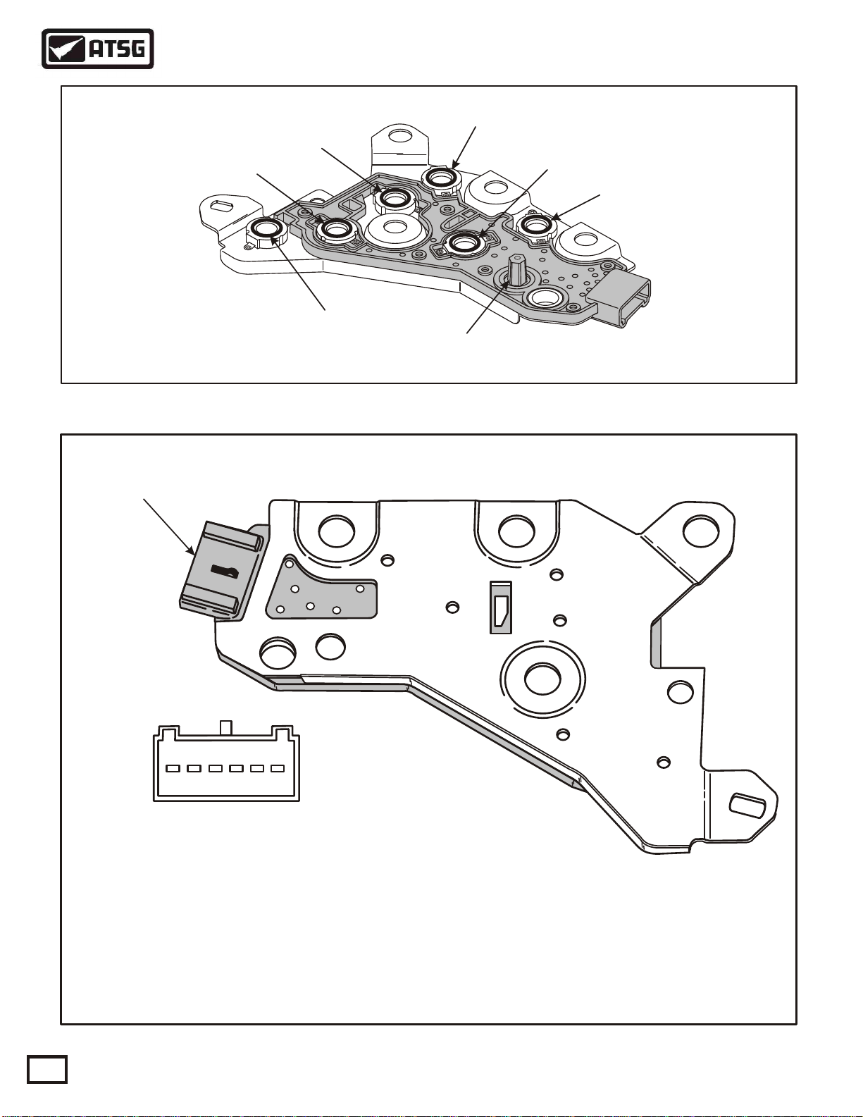
NOT USED (N/O)
Terminal Identification
Cast In Connector Here
Technical Service Information
PRESSURE SWITCH ASSEMBLY
NOT USED (N/O)
"E" SHIFT (N/O)
"D" SHIFT (N/O)
"C" SHIFT (N/O)
REVERSE (N/C)
TEMP SENSOR
(THERMISTER)
Copyright © 2000 ATSG
Figure 22
PRESSURE SWITCH CONNECTOR
PIN FUNCTION AND IDENTIFICATION
A
B
C
D
E
F
A B C D E F
Pressure Switch Assembly
Receptacle (Face View)
(A) SHIFT "C" SIGNAL TO PCM (CASE CONNECTOR TERMINAL "D")
(B) SHIFT "D" SIGNAL TO PCM (CASE CONNECTOR TERMINAL "F")
(C) SHIFT "E" SIGNAL TO PCM (CASE CONNECTOR TERMINAL "E")
(D) REVERSE SWITCH TO PCM (CASE CONNECTOR TERMINAL "K")
(E) TEMP SENSOR HIGH (CASE CONNECTOR TERMINAL "G")
(F) TEMP SENSOR LOW (CASE CONNECTOR TERMINAL "H")
20
Copyright © 2000 ATSG
Figure 23
AUTOMATIC TRANSMISSION SERVICE GROUP
Page 21
Technical Service Information
PRESSURE SWITCH CONNECTOR
PIN FUNCTION AND IDENTIFICATION
TCM "J2" (Red)
Connector
21
1
2
3
4
10
20
Yellow TRANS ID
Blue
Pink
White
Green
Tan
Green
Transmission
Case Connector
Figure 24
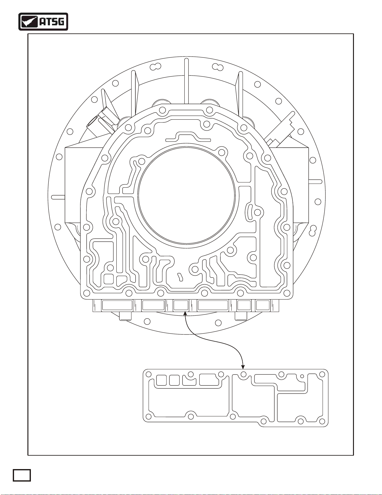
PRESSURE SWITCH ASSEMBLY
The Pressure Switch Assembly (PSA) is made up of
three normally open switches and one normally
closed switch. There are also 2 additional switches in
the PSA that are not used. All switches and their
locations are identified in Figure 22. Fluid pressure is
fed from shift valves C, D, and E to C, D, and E
switches, and from the manual valve to the reverse
switch. This logic indicates the current transmission
operating range to the TCM.
The three pressure switches corresponding to the
shift valves are normally open (N/O) when there is no
pressure to the switch, so that electrical current is
stopped at the switch. When pressure is routed to the
switch from the shift valves, the switch closes and
allows current to flow from the positive contact and
through the switch. Refer to Figure 24.
The pressure switch corresponding to reverse is a
normally closed (N/C) switch, and pressure is fed to
the switch when the transmission is placed into the
reverse position.
The Pressure Switch Assembly also contains the
temperature sensor (thermister) to notify the TCM of
the current sump temperature. Changes in fluid
temperature are indicated by changes in sensor
resistance. Increasing temperature will create
decreased sensor resistance.
Pressure Switch
Connector
Tan
T
Lt Green
D
Blue
Red
Ta n
Orange
Black
C
A
NOT USED
D
BF
E
CE
NOT USED
R
DK
EG
FH
PRESSURE SWITCH
PRESSURE SWITCH
ASSEMBLY
ASSEMBLY
Copyright © 2000 ATSG
TEMP
SENSOR
The PSA terminal identification and functions are
illustrated in Figure 23 to assist in switch diagnosis.
There is also a complete wiring schematic from the
Pressure Switch Assembly through the transmission
case connector and to the TCM shown in Figure 24.
We have also provided a pressure switch logic state
chart in Figure 25.
Pressure Switch Logic State Chart
Range
Park
Rev
Neut
OD
4
3
2
1
"C"
On
On
On
Off
On
On
Off
Off
"D"
On
On
On
Off
Off
Off
Off
On
"E"
On
On
On
On
On
Off
Off
Off
Reverse
Off
On
Off
Off
Off
Off
Off
Off
Figure 25
AUTOMATIC TRANSMISSION SERVICE GROUP
21
Page 22
Technical Service Information
RETRIEVING DIAGNOSTIC CODES
A or H
Pause
Break
Scroll
Lock
Print
Home
Scrn
Backspace
F12
F11
_
-
F10
F9
0
F8
9
F7
F6
7
F5
6
F4
5
F3
F2
3
F1
2
ESC
1
W
~
`
Q
b
Ta
A
ps Lock
Ca
Shift
rl
Ct
Fn
Y
4
T
R
G
E
F
D
V
S
C
X
Z
Alt
n
Wi
P
8
O
I
L
U
K
<
J
,
H
M
N
B
PgUp
+
|
=
\
}
PgDn
]
r
{
Ente
[
:
;
>
.
Alt
End
"
ift
'
Sh
?
/
Del
Ins
C or SB or L
J-1939 Connector
Copyright © 2000 ATSG
Figure 26
CHECK TRANS LIGHT
The electronic control system is programmed to
inform the operator of any type problem with the
transmission system and automatically take action to
protect the operator, vehicle and transmission. To do
this, the TCM turns on the Check Trans light on the
instrument panel, which will notify the operator that a
Diagnostic Trouble Code (DTC) has been stored in
the TCMs memory.
Each time the engine is started, the Check Trans
light will illuminate momentarily and then go off after
a few seconds. This momentary lighting is to ensure
that the Check Trans light circuit is working properly.
Illumination of the Check Trans light at any time after
start-up, indicates that the TCM has stored a DTC, or
the TCM is not working properly. Anytime the Check
Trans light is on, upshifts and downshifts will be
restricted and direction changes may not occur. The
converter clutch is also shut off when transmission
shifting is restricted.
If power is interrupted while the transmission is
operating in a forward range, the default positions of
the shift valves and solenoids will enable application
of two clutches to maintain forward range operation
(Either 3 or 5th). If power is interrupted while the
transmission is operating in R(Reverse) or
N(Neutral), the transmission defaults to or continues
Neutral operation untill a key cycle.
The operator may turn off and restart the engine,
and the manual selector lever will provide reverse
when in R, Neutral when in P/N, and 3rd Gear when
in any forward range, regardless of the range where
the failure occured.
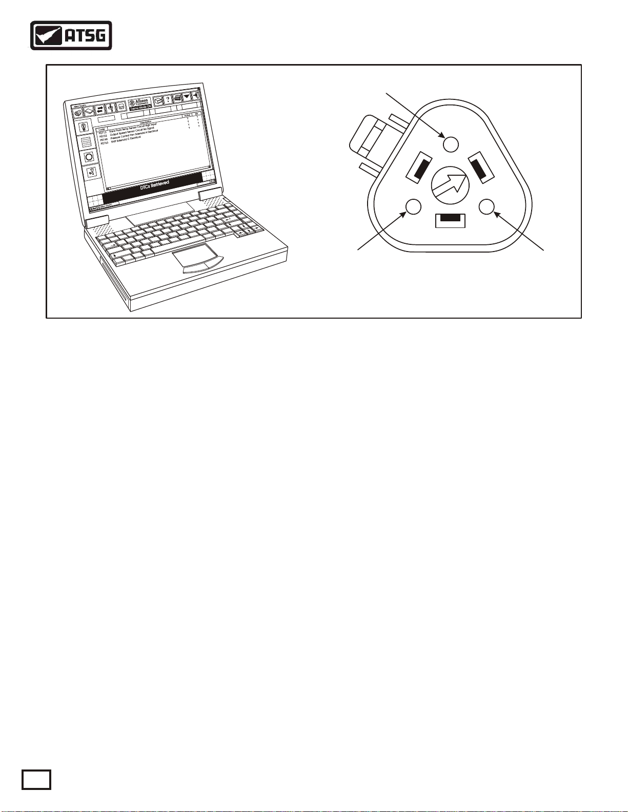
RETRIEVING DIAGNOSTIC CODES
Currently you must use PC Tool Software called
TransPro® which is available through Kent-Moore
Heavy-Duty Division, and must be loaded onto a
Windows 95/98 Lap-T op PC as shown in Figure 26.
The TransPro® software transmits and recieves data
to and from the TCM via the J-1939 connector, as
shown in Figure 26, processes the data, and displays
the appropriate information on the screen.
The use of TransPro® is describeded in detail in the
instruction manual that is furnished with each set of
software. We have provided you with a typical
screen, that is utilized in the TransPro® software, for
retrieving DTCs in Figure 27.
Hopefully aftermarket scanner manufacturers will
be able to provide us with a cartridge for the more
popular scanners in the future.
22
AUTOMATIC TRANSMISSION SERVICE GROUP
Page 23
Technical Service Information
Allison TransPro
3 4 6 9 1 2 6 0
5 8 1 3 6 5 2 2
6 4 5 4 8 9 1 0
4 3 3 6 7 3 3 8
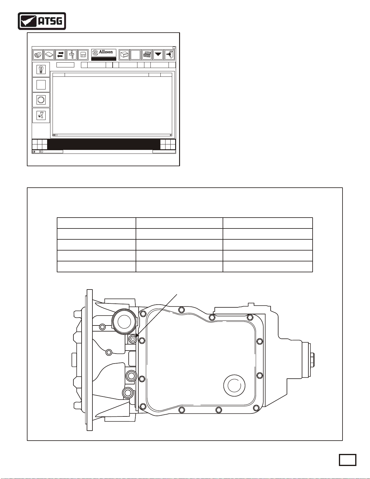
TYPICAL TransPro® DISPLAY
Transmission
Demo Mode ON
P0713 Trans Fluid Temp Sensor Circuit High Input Y Y
P0722 Output Speed Sensor Circuit No Signal
P0748 Pressure Control Trim Solenoid A Electrical
P0763 Shift Solenoid C Electrical
DTCs RetrievedDTCs Retrieved
Allison TransProStartStart
Copyright © 2000 ATSG
Figure 27
?
MAIN PRESSURE TAP LOCATION AND SPECIFICATIONS
ActiveDescriptionCode
Y Y
Y Y
Y Y
MIL
10:45 AM
LINE PRESSURE TEST
Check transmission fluid level. All transmission
XX
fluid level and pressure checks must be made at
normal operating temperatures (160-200°F).
Connect a 0-300 psi oil pressure guage to the main
pressure tap as illustrated in Figure 28, and compare
readings with the pressure chart in Figure 28.
Take precautions against vehicle movement during
the pressure tests, and use a guage with an extended
line so that it can be read from inside the vehicle.
Range
PARK/NEUTRAL
REVERSE
FORWARD (TCC Off)
FORWARD (TCC On)
MAIN PRESSURE TEST SPECIFICATIONS
Pressure @ 600 RPM
900-1655 kpa (130-240 psi)
800-1380 kpa (115-200 psi)
800-1380 kpa (115-200 psi)
Main Pressure Tap
TO COOLERTO COOLER
FROM COOLERFROM COOLER
Pressure @ 1200 RPM
1515-1795 kpa (220-260 psi)
1515-1795 kpa (220-260 psi)
1515-1795 kpa (220-260 psi)
1000-1170 kpa (145-170 psi)
Figure 28
AUTOMATIC TRANSMISSION SERVICE GROUP
23
Page 24
Technical Service Information
BELL HOUSING OIL PASSAGE IDENTIFICATION
16
16
9
15
16
16
29536810
3
2
1
13
2
9
14
2
10
3
3
16
3
1
8
1
16
7
1
6
11
1. PUMP SUCTION
2. LINE PRESSURE
3. OVERAGE (CONV RELEASE)
4. CONVERTER IN
5. CONVERTER OUT
6. TO COOLER
7. FROM COOLER
8. LUBE OIL
9. LOCK-UP APPLY
10. C1 CLUTCH
11. C2 CLUTCH
12. LOCK-UP SIGNAL
13. CUT-BACK (5TH GEAR)
14. LINE - TO FILTER
15. LINE - FROM FILTER
16. EXHAUST
24
15 14
16
2
16
6
BOTTOM BELL HOUSING COOLER MANIFOLD SURFACE
Figure 29
AUTOMATIC TRANSMISSION SERVICE GROUP
7
16
Copyright © 2000 ATSG
Page 25
Technical Service Information
PUMP COVER SPACER PLATE OIL PASSAGE I.D.
16
16
16
16
16
3
3
2
8
1
2
7
6
1
16
16
2
16
3
2
16
9
16
9
1. PUMP SUCTION
2. LINE PRESSURE
3. OVERAGE (CONV RELEASE)
4. CONVERTER IN
5. CONVERTER OUT
6. TO COOLER
7. FROM COOLER
8. LUBE OIL
9. LOCK-UP APPLY
10. C1 CLUTCH
11. C2 CLUTCH
12. LOCK-UP SIGNAL
13. CUT-BACK (5TH GEAR)
14. LINE - TO FILTER
15. LINE - FROM FILTER
16. EXHAUST
11
10
1
2
13
Figure 30
AUTOMATIC TRANSMISSION SERVICE GROUP
15
14
Copyright © 2000 ATSG
25
Page 26
Technical Service Information
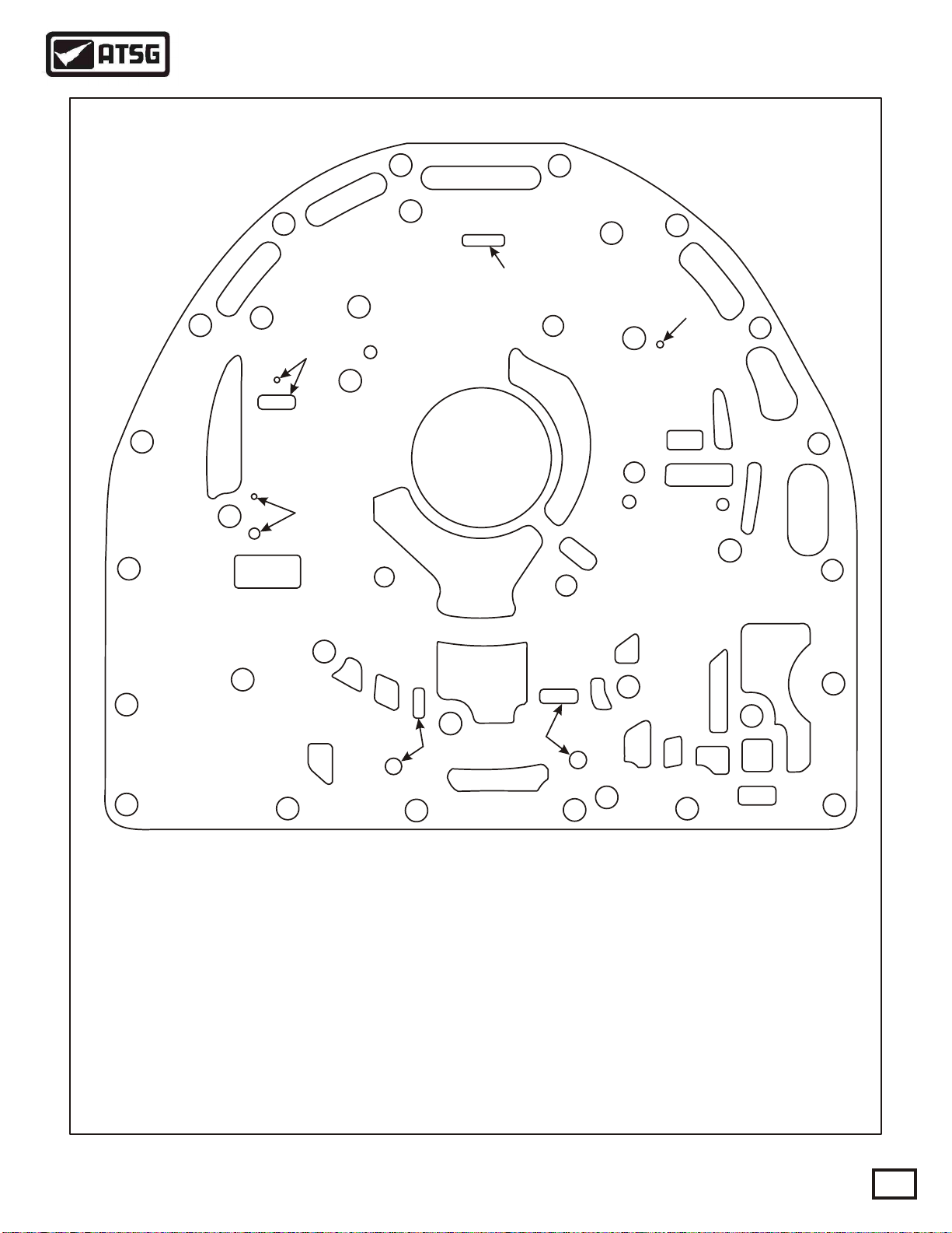
MAIN CASE "FRONT" PASSAGE I.D.
16
16
16
1. PUMP SUCTION
2. LINE PRESSURE
3. OVERAGE (CONV RELEASE)
4. CONVERTER IN
5. CONVERTER OUT
6. TO COOLER
7. FROM COOLER
8. LUBE OIL
9. LOCK-UP APPLY
10. C1 CLUTCH
11. C2 CLUTCH
12. LOCK-UP SIGNAL
13. CUT-BACK (5TH GEAR)
14. LINE - TO FILTER
15. LINE - FROM FILTER
16. EXHAUST
16
16
11
16
N/A
9
13
2
1
10
14
15
Copyright © 2000 ATSG
26
Figure 31
AUTOMATIC TRANSMISSION SERVICE GROUP
Page 27
Technical Service Information
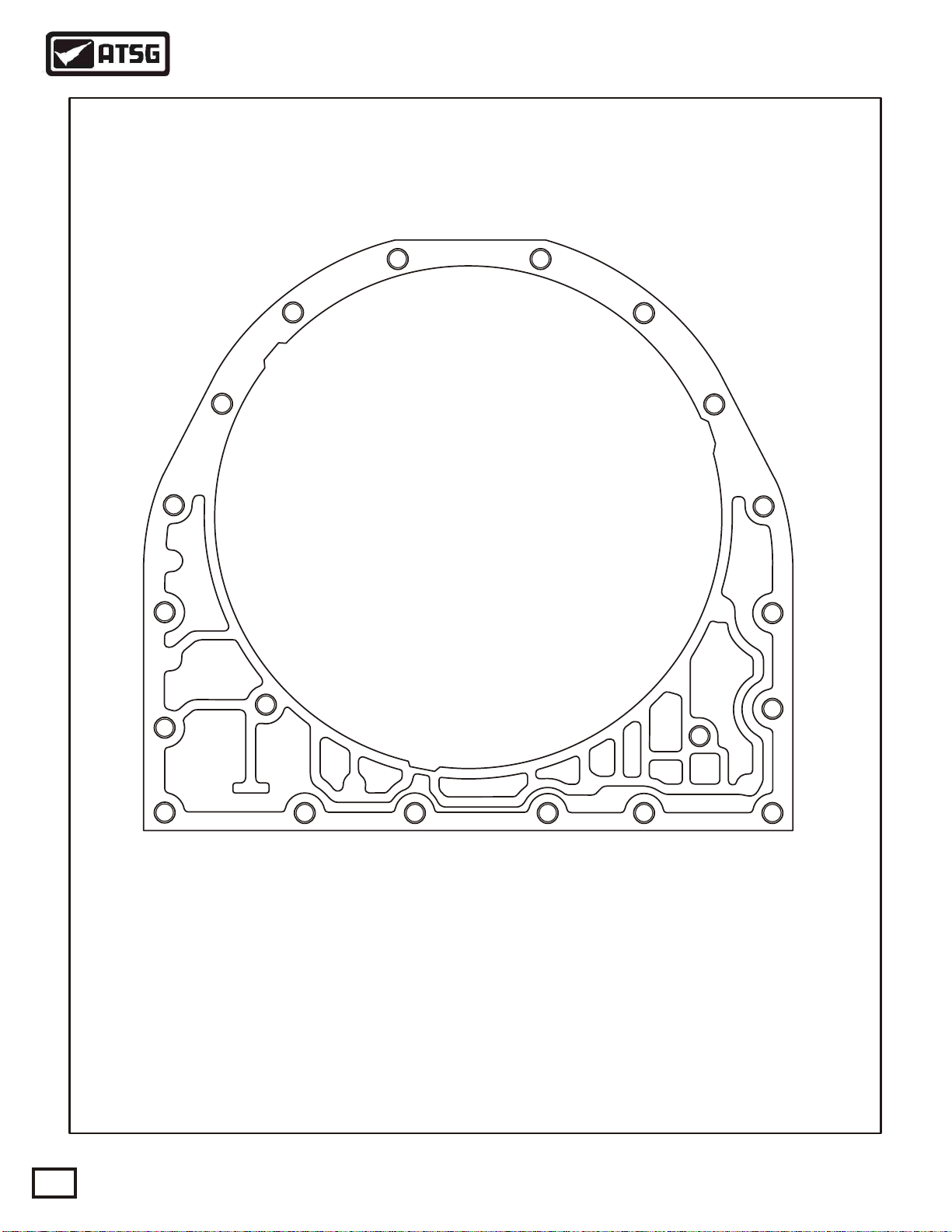
MAIN CASE "REAR" PASSAGE I.D.
15
14
C5 CLUTCH
Figure 32
COOLER MANIFOLD PASSAGE I.D.
MAIN LINE
PRESSURE TAP
TO
TO
CLR
CLR
Copyright © 2000 ATSG
FROM
76
FROM
CLR
CLR
6. TO COOLER
7. FROM COOLER
14. LINE - TO FILTER
Figure 33
AUTOMATIC TRANSMISSION SERVICE GROUP
Copyright © 2000 ATSG
27
Page 28
Technical Service Information
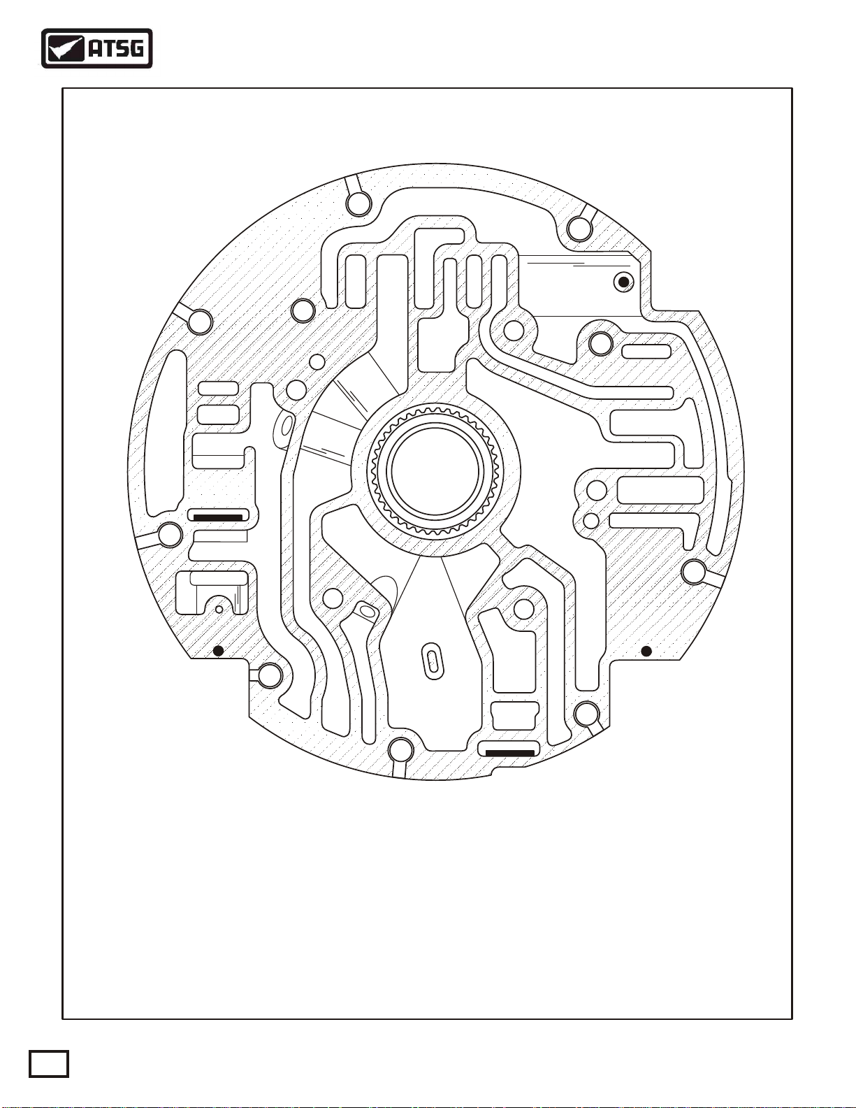
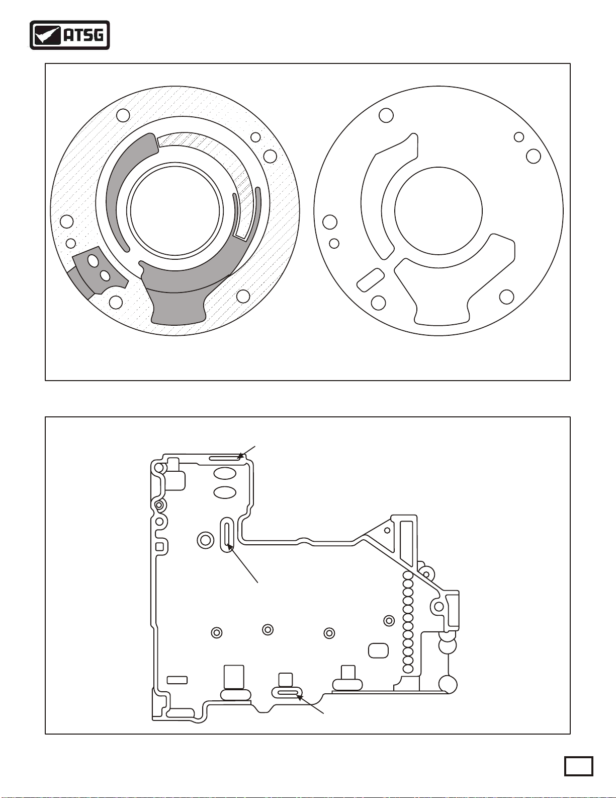
PUMP COVER OIL PASSAGE I.D.
9
3
16
9
5
6
3
3
8
6
8
1
11
4
4
16
12
9
2
2
1
16
2
10
12
2
13
3
16
9
28
7
1. PUMP SUCTION
2. LINE PRESSURE
3. OVERAGE (CONV RELEASE)
4. CONVERTER IN
5. CONVERTER OUT
6. TO COOLER
7. FROM COOLER
8. LUBE OIL
9. LOCK-UP APPLY
10. C1 CLUTCH
11. C2 CLUTCH
12. LOCK-UP SIGNAL
13. CUT-BACK (5TH GEAR)
16. EXHAUST
AUTOMATIC TRANSMISSION SERVICE GROUP
6
1
10
16
Copyright © 2000 ATSG
Figure 34
Page 29
Technical Service Information
OIL PUMP PASSAGE I.D.
2
2
14
1. PUMP SUCTION
2. LINE PRESSURE
14. EXHAUST
14
1
1
Copyright © 2000 ATSG
Figure 35
SHIFT VALVE BODY "TOP VIEW" PASSAGE I.D.
Exhaust
Exhaust
Exhaust
Figure 36
AUTOMATIC TRANSMISSION SERVICE GROUP
Copyright © 2000 ATSG
29
Page 30

Technical Service Information
LEGEND FOR FIGURES 38, 39, AND 41.
Passage No.
1
2
9
10
11
12
13
14
16
15
30
31
32
33
34
35
36
37
38
39
40
41
42
43
44
45
46
47
48
49
50
51
52
53
54
55
56
57
Reverse Park/Neut 1st 2nd
Pump Suction
Main Line Pressure
TCC Apply
Exhaust Backfill/ C-1 Clutch
C-2 Clutch/Exhaust Backfill C-2 Clutch
Lock-Up Signal
Cut-Back (5th Gear)
Control Main Line Pressure To Filter
Exhaust To Sump
Control Main Line Pressure From Filter
Reverse Pressure Switch
"D" Shift Valve Pressure Switch
"E" Shift Valve Pressure Switch
"C" Shift Valve Pressure Switch
C-3 Clutch C-3 Clutch C-3 Clutch
Exhaust Backfill
Main Line Pressure
Exhaust Backfill
C-3/B Trim
Exhaust Backfill
C-3/B Trim OD/B TrimC-4/B Trim
C-1/B Trim
"D" Signal TCC Interlock
Exhaust Backfill/ C-3 Clutch EBF/C-3 Clutch
C-4 Clutch
C-5 Clutch
Exhaust Backfill
"A" Trim Solenoid Signal
"B" Trim Solenoid Signal
"A" Clutch Trim
"B" Clutch Trim
"A" Clutch Trim Feedback
"B" Clutch Trim Feedback
"D" Solenoid Signal
"E" Solenoid Signal
"C" Solenoid Signal
C-1/Main
Control Main After "B" Solenoid Screen
B Trim
"E" Shift Valve Interlock
C-2/EBF
Exhaust Backfill/C-5 Clutch (Power Off State)
C-3/EBF
C-2/EBF
Thermister
Exhaust Backfill
C-1/Main
3rd 4th 5th
EBF/ C-1 ClutchC-1 Clutch
C-1/B Trim
C-2/B Trim
C-1/B TrimC-1/B Trim
C-2/B Trim
C-4/EBF OD/EBF
C-2/Main
Exhaust
C-2/Main
C-1/EBF
Cut-BackC-3/EBF
C-1/EBFC-1/EBF
30
Copyright © 2000 ATSG
Figure 37
AUTOMATIC TRANSMISSION SERVICE GROUP
Page 31

56
56
37
30
30
37
47
10
37
10
30
55
11
11
16
16
Technical Service Information
SHIFT VALVE BODY "BOTTOM VIEW" PASSAGE I.D.
56
37
47
13
13
37
37
11
16
37
31
56
31
13
34
40
36
56
37
16
31
37
37
53
49
2
44
31
53
16
32
2
49
54
47
37
35
57
2
51
37
52
45
44
37
2
37
37
57
16
37
2
31
44
53
54
41
57
33
15
52
46
44
44
41
2
2
14
37
2
2
37
14
32
32
15
40
16
LEGEND FOUND ON PAGE 30.
15
46
16
16
41
37
2
15
15
40
15
48
Figure 38
AUTOMATIC TRANSMISSION SERVICE GROUP
Copyright © 2000 ATSG
Copyright © 2000 ATSG
31
Page 32

Technical Service Information
MAIN VALVE BODY "TOP VIEW" PASSAGE I.D.
16
16
16
16
33
15
32
42
38
14
14
30
16
37
32
16
40
2
40
32
16
16
16
30
39
38
2
37
2
2
16
37
41
2
43
16
33
2
44
44
37
16
39
15
32
31
15
44
45
35
45
37
40
57
2
57
44
37
51
37
2
53
32
11
30
2
14
16
44
34
34
36
34
35
51
40
5454
47
36
56
37
53
16
16
16
2
9
9
31
56
36
51
15
34
40
40
56
55
47
15
37
11
9
5
11
13
2
10
10
30
6
9
15
37
30
15
9
37
11
30
31
32
16
16
11
14
16
LEGEND FOUND ON PAGE 30.
Figure 39
AUTOMATIC TRANSMISSION SERVICE GROUP
14
10
9
13
15
14
Copyright © 2000 ATSG
Page 33

Technical Service Information
MAIN VALVE BODY "BOTTOM VIEW" PASSAGE I.D.
16
30
39
16
16
16
31
30
DuPage
29536840
30
16
16
32
38
50
33
16
16. EXHAUST.
30. REVERSE PRESSURE SWITCH.
31. "D" SHIFT VALVE PRESSURE SWITCH.
32. "E" SHIFT VALVE PRESSURE SWITCH.
33. "C" SHIFT VALVE PRESSURE SWITCH.
38. "A" TRIM SOLENOID SIGNAL.
39. "B" TRIM SOLENOID SIGNAL.
50. FLUID TEMPERATURE SENSOR (THERMISTER).
AUTOMATIC TRANSMISSION SERVICE GROUP
Copyright © 2000 ATSG
Figure 40
33
Page 34

Technical Service Information
TYPICAL VALVE BODY SPACER PLATE
56
36
16
3534
15
16
43
37
41
39
38
37
40
2
42
16
56
30
15
37
37
9
14
11
55
30
10
30
13
47
13
37
11
47
14
55
2
10
31
2
53
56
36
40
34
51
53
31
35
47
54
51
32
45
37
44
37
40
15
57
37
2
2
33
2
44
57
54
53
44
31
2
2
2
37
16
11
32
32
14
14
6837
34
LEGEND FOUND ON PAGE 30.
Copyright © 2000 ATSG
Figure 41
AUTOMATIC TRANSMISSION SERVICE GROUP
Page 35

Technical Service Information
MAIN CASE "BOTTOM VIEW" PASSAGE I.D.
16
11
16
35
1
29536808
34 16
36
56
10
14
13
2
15
9
1. SUCTION.
2. MAIN LINE PRESSURE.
9. TCC APPLY.
10. C-1 CLUTCH.
11. C-2 CLUTCH.
13. CUT-BACK (OverDrive).
14. CONTROL MAIN TO FILTER.
15. CONTROL MAIN FROM FILTER.
16. EXHAUST TO SUMP .
34. C-3 CLUTCH.
35. C-4 CLUTCH.
36. C-5 CLUTCH.
56. C-5 CLUTCH (Power -Off State).
AUTOMATIC TRANSMISSION SERVICE GROUP
Figure 42
Copyright © 2000 ATSG
Copyright © 2000 ATSG
35
Page 36

Technical Service Information
TRANSMISSION DISASSEMBLY
EXTERNAL COMPONENTS
1. Remove the six PTO cover retaining bolts or
the Power Take Off whichever it is equipped
with, on the right hand side of the transmission
as shown in Figure 43.
2. Install holding fixture similar to the one shown
in Figure 43, onto the PTO surface, to be used
with the bench fixture base.
Caution: Because of the mass and the weight
of this unit, we feel it necessary to use holding
fixture shown in Figure 43, with the fixture
base or in a suitable turn-over stand.
3. Using a suitable hoist, lift the transmission and
install into bench fixture base, or the suitable
turn-over stand.
4. With transmission assembly locked, in the pan
facing down position, remove the converter by
pulling it straight out (See Figure 44).
Caution: This torque converter weighs about
60 pounds, so exercise extreme caution.
5. Remove the engine speed sensor, turbine speed
sensor and output speed sensor, as shown in
Figure 45.
Note: The engine speed sensor, if equipped,
the turbine speed sensor, and the output speed
sensor on 2WD models are all the same part
number (See Figure 45).
6. Remove and discard the "O" rings from the 3
speed sensors (See Figure 45).
7. Remove the Neutral Start Back-Up switch from
the side of case, as shown in Figure 45.
Note: The NSBU Switch is exactly the same
as the 4L60-E switch (See Figure 45).
8. Rotate the transmission in the fixture so that
the oil pan is facing up (See Figure 46).
Continued on Page 38
36
9
.8
9
.8
9
.8
9
.8
9
.8
9
.8
9
.8
9
.8
9
9
.8
.8
W
A
U
3
3
9
X
X
n
X
n
.
X
P
o
R
X
-
i
O
X
C
s
X
so
S
R
X
i
s
X
O
l
i
A
T
X
l
O
X
AN
-
I
M
X
L
X
D
m
X
A
N
X
I
A
R
X
s
X
,
E
X
S
N
X
I
n
E
L
X
X
G
-
O
F
X
a
P
X
X
A
O
X
r
N
N
X
X
X
A
O
I
X
I
X
X
D
S
T
I
N
X
X
V
I
-
I
X
D
X
X
X
X
X
X
X
X
X
X
-
X
-
X
L
X
X
E
X
X
D
X
D
I
X
T
S
X
MO
-
E
X
I
X
X
R
X
X
E
X
S
TE
X
A
0
-
D
0
0
X
.
1
X
X
O
X
N
X
L
1
2
A
X
I
F
R
X
9
E
9
S
X
X
N
X
C
X
X
F
X
E
X
X
X
X
X
X
X
X
9
.
8
9
.
8
9
.
8
9
.
8
9
.
8
9
.
8
BENCH FIXTURE BASE
HOLDING FIXTURE
Copyright © 2000 ATSG
Figure 43
AUTOMATIC TRANSMISSION SERVICE GROUP
Page 37

Technical Service Information
1
3
0
1
3
5
9
2
n
n
onAlli
on
o
o
s
s
s
s
Alli
Alli
Alli
ENGINE SPEED SENSOR
(SOME MODELS)
TURBINE SPEED SENSOR
(ALL MODELS)
1
3
0
1
3
5
9
2
Figure 44
lli
lli
llis
llis
A
A
A
Copyright © 2000 ATSG
OUTPUT SPEED SENSOR
(2WD MODELS)
nA
n
n
n
o
o
so
so
NSBU SWITCH
29536408
Figure 45
AUTOMATIC TRANSMISSION SERVICE GROUP
12450016
Copyright © 2000 ATSG
37
Page 38

Technical Service Information
CONTINUED FROM PAGE 36
9. Remove the twelve bottom pan retaining bolts,
using a 13 mm socket (See Figure 46).
10. Remove the bottom oil pan (See Figure 46).
11. Remove and discard the bottom pan gasket, as
shown in Figure 46.
12. Remove and discard the bottom pan filter and
filter seal, as shown in Figure 47.
13. Remove the inside detent roller and spring
assembly retaining bolts, using an 8mm socket,
as shown in Figure 48.
14. Remove the inside detent roller and spring
assembly, as shown in Figure 48.
15. Remove the pass through case connector from
the case bore using the Teckpakä GM harness
removal tool, as shown in Figure 49.
16. Remove the 15 valve body to case retaining
bolts, using an 8mm socket (See Figure 50).
Note: Remove "Only" the valve body to case
bolts that are shaded as shown in Figure 50.
Continued on Page 40
BOTTOM PAN
PAN BOLTS
12 REQUIRED
BOTTOM PAN
FILTER
PAN GASKET
FILTER SEAL
1
1
1
1
8
8
8
1
1
1
1
8
8
8
8
D
u
P
D
u
P
a
g
8
8
0
0
8
8
8
8
0
0
6
6
8
8
3
3
6
6
5
5
3
3
9
9
5
5
2
2
9
9
2
2
e
8
8
0
0
8
8
8
8
0
0
6
6
8
8
3
3
6
6
5
5
3
3
9
9
5
5
2
2
9
9
2
2
age
8
38
Copyright © 2000 ATSGCopyright © 2000 ATSG
Figure 46 Figure 47
AUTOMATIC TRANSMISSION SERVICE GROUP
Page 39

Technical Service Information
DETENT ROLLER AND
SPRING ASSEMBLY
DETENT ROLLER AND
SPRING ASSEMBLY
RETAINING BOLTS
1
1
1
1
8
8
8
8
Du
Pag
8
8
0
0
8
8
8
8
0
0
6
6
8
8
3
3
6
6
5
5
3
3
9
9
5
5
2
2
9
9
2
2
e
TECKPAKä
GM HARNESS
REMOVAL TOOL
9
.
8
9
.
8
9
.
8
9
.
8
9
.
8
X
X
X
X
9
X
9
X
X
1
F
S
0
2
X
E
X
E
0
FC
1
RI
X
X
0
A
X
N
X
S
L
D
E
X
M
X
N
A
RI
T
X
O
O
X
E
E
S
D
.
X
E
X
L
X
DI
T
T
I
X
V
D
I
S
r
X
I
I
N
O
DI
an
X
X
N
A
O
AN
X
X
-
F
A
G
X
X
-
X
PO
l
E
s
N
X
X
-
l
X
X
L
m
E
i
I
R
X
-
X
X
S
X
so
A
,
L
-
X
I
X
X
X
M
N
i
D
O
X
X
s
X
X
I
T
A
O
s
X
X
X
NA
X
R
i
n
S
X
X
X
X
C
o
X
O
X
X
-
R
n
P
X
X
-
X
.
X
X
-
X
X
X
-
X
X
X
-
X
X
X
X
X
X
X
X
X
X
X
9
X
X
U
3
A
X
3
W
Copyright © 2000 ATSG Copyright © 2000 ATSG
Figure 48 Figure 49
9
.
8
9.
8
9
.
8
9
.
9
.
8
8
SIX VALVE BODY
TO CASE BOLTS
FOUR VALVE BODY
TO CASE BOLTS
29536808
29536840
DuPage
FIVE VALVE BODY
TO CASE BOLTS
Copyright © 2000 ATSG
Figure 50
AUTOMATIC TRANSMISSION SERVICE GROUP
39
Page 40

Technical Service Information
CONTINUED FROM PAGE 38
17. After the 15 valve body bolts are removed, you
can remove the valve body, ensuring that you
disengage the manual valve pin from the inside
detent lever, as shown in Figure 51.
18. Set the complete valve body assembly aside
for the component rebuild process.
19. Remove the external oil filter from the cooler
manifold or the bell housing, depending on the
design, as shown in Figure 52.
20. Remove the cooler manifold assembly retaining
bolts, as shown in Figure 54.
21. Remove the cooler manifold assembly from the
bell housing, as shown in Figure 54.
22. Remove and discard the 2 cooler manifold
gaskets, as shown in Figure 54.
23. Rotate the transmission in the fixture so that the
bell housing is facing up (See Figure 53).
Continued on Page 42
VALVE BODY
TO CASE BOLTS
15 REQUIRED
VALVE BODY
TO CASE BOLTS
15 REQUIRED
D
u
P
ag
e
1
1
1
1
8
8
8
8
8
8
0
0
8
8
8
8
0
0
6
6
8
8
3
3
6
6
5
5
3
3
9
9
5
5
2
2
9
9
2
2
40
Copyright © 2000 ATSG
Figure 51
AUTOMATIC TRANSMISSION SERVICE GROUP
Page 41

EXTERNAL
OIL FILTER
8
8
8
8
0
0
0
8
0
8
8
8
6
6
6
6
3
3
3
5
3
5
5
5
9
9
9
2
9
2
2
2
Technical Service Information
1
1
1
1
8
8
8
8
7
6
5
3
Copyright © 2000 ATSG
Figure 52
4
3
1
11
11
88
88
08
08
08
08
368
368
368
368
95
95
2
2
95
95
2
2
2
9
5
3
1
0
3
1
2
1. TRANSMISSION CASE.
2. TRANSMISSION BELL HOUSING.
3. COOLER MANIFOLD SPACER PLATE GASKET (2 REQUIRED).
4. COOLER MANIFOLD SPACER PLATE.
5. COOLER MANIFOLD ASSEMBLY .
6. COOLER MANIFOLD RETAINING BOLT, M8 x 1.25 x 30 (8 REQ).
7. COOLER MANIFOLD RETAINING BOLT, M8 x 1.25 x 40 (4 REQ).
Copyright © 2000 ATSGCopyright © 2000 ATSG
Figure 53 Figure 54
AUTOMATIC TRANSMISSION SERVICE GROUP
41
Page 42

Technical Service Information
1
2
1
24. Remove 2 bell housing bolts from each side of
CONTINUED FROM PAGE 40
the case that are not inside the bell housing, as
shown in Figure 55.
25. Remove the bell housing to case bolts that are
shaded, from inside the bell housing, as shown
in Figure 56.
Note: Remove the shaded bolts only, as shown
in Figure 56. There will be 11 bolts that are
50mm long and 5 bolts that are 70mm long.
The remaining bolts retain pump to bell.
26. Remove bell housing and oil pump assembly
from the transmission case, by lifting straight
up, as shown in Figure 55.
2
9
5
3
1
0
3
1
27. Remove and discard the pump spacer plate to
case gasket (See Figure 55).
1
28. Set the bell housing and pump assembly aside
for the component rebuild process.
29. Remove the C1/C2 clutch housing from the
1
3
case by lifting straight up using the turbine, as
shown in Figure 57.
Note: Remove the sun gear/planetary carrier
thrust bearing if it is not stuck to sun gear as
shown in Figure 57.
4
5
1. BELL HOUSING TO CASE BOLTS, M10 X 1.5 X 50,
(11 INSIDE BELL, 2 EACH SIDE ON OUTSIDE, TOTAL 15 REQ.)
2. BELL HOUSING TO CASE BOLTS, M10 X 1.5 X 70, (5 REQUIRED)
3. BELL HOUSING AND PUMP ASSEMBLY
4. BELL HOUSING SPACER PLATE TO CASE GASKET
5. MAIN TRANSMISSION CASE ASSEMBLY
Figure 55 Figure 56
1
3
0
3
5
9
1
2
5 BOLTS 70mm IN LENGTH
OTHER 11 ARE 50mm IN LENGTH
Copyright © 2000 ATSGCopyright © 2000 ATSG
42
AUTOMATIC TRANSMISSION SERVICE GROUP
Page 43

Technical Service Information
30. Set C1/C2 clutch housing aside for component
rebuild process that is covered later.
31. Rotate transmission case so that the extension
housing is facing up as shown in Figure 58.
32. Remove the yoke from the transmission if it is
equipped with one, as shown in Figure 58.
Note: Some models are equipped with the
parking brake as shown in Figure 58. Four
Wheel Drive models will have neither.
Continued on Page 45
C1/C2 CLUTCH
HOUSING ASSEMBLY
(SOME MODELS)
(SOME MODELS)
THRUST
BEARING
9.
8
9.
8
9.
8
9.
8
9.
8
X
X
X
X
9
X
9
X
X
1
F2
SE
0
X
E
X
0
F
1
R
X
C
X
0
I
A
X
N
X
S
L
D
E
X
M
X
N
A
R
T
I
X
O
O
X
E
E
S
D
.
X
E
X
L
X
DI
T
T
I
X
V
D
I
SI
r
X
I
N
O
DI
a
X
X
N
A
O
A
X
X
-
n
NA
F
G
X
X
-
X
P
l
E
s
O
N
X
X
-
l
X
X
L
mis
E
i
I
R
X
-
X
X
S
X
s
A
,
L
-
X
I
X
X
X
M
N
o
DI
O
X
X
X
X
T
A
O
s
X
X
X
NA
X
R
io
n
S
X
X
X
X
C
X
O
X
X
-
R
n
P
X
X
-
X
.
X
X
-
X
X
X
-
X
X
X
-
X
X
X
X
X
X
X
X
X
X
X
9
X
X
U
3
A
X
3
W
9.
8
9
.
8
9
.
8
9.
8
9.
8
Copyright © 2000 ATSGCopyright © 2000 ATSG
Figure 57 Figure 58
AUTOMATIC TRANSMISSION SERVICE GROUP
43
Page 44

Technical Service Information
EXTENSION
HOUSING
EXTENSION HOUSING
BOLTS M10 X 1.5 X 40
(16 REQUIRED)
P3 PLANETARY
CARRIER ASSEMBLY
OUTPUT
SHAFT
THRUST
BEARING
EXTENSION
HOUSING
GASKET
P3 SUN GEAR
C
C
1000
1000
310
310
1
1
00
00
8
8
8
8
00
00
1
1
0
0
/2
/2
T
A
T
A
2
2
R
R
1
1
1
1
r
r
M8
M8
a
a
0
0
1
1
nsmi
nsmi
l
l
11
11
lis
lis
s
s
s
s
o
o
ion
ion
n
n
C
C
1000
1000
310
310
1
1
00
00
8
8
8
8
00
00
1
1
0
0
/2
/2
T
A
T
A
2
2
R
R
1
1
1
1
r
r
M8
M8
a
a
0
0
1
1
nsmi
nsmi
l
l
11
11
lis
lis
s
s
s
s
o
o
ion
ion
n
n
44
Copyright © 2000 ATSG
Figure 59
AUTOMATIC TRANSMISSION SERVICE GROUP
Copyright © 2000 ATSG
Figure 60
Page 45

Technical Service Information
CONTINUED FROM PAGE 43
33. Remove the 16 extension housing bolts, using a
15mm socket (See Figure 59).
34. Remove the extension housing assembly and
set aside for the component rebuild process,as
shown in Figure 59.
35. Remove and discard the extension housing
gasket, as shown in Figure 59.
36. Grasp the output shaft splines and lift straight
up, removing the output shaft and P3 planetary
carrier as an assembly (See Figure 60).
37. Remove the P3 sun gear and the thrust bearing
as shown in Figure 60.
38. Grasp the main shaft splines and lift straight up
removing the main shaft, P2 sun gear and the
sun gear spacer, as shown in Figure 62.
39. Remove the parking pawl shaft by pulling up
and twisting motion at the same time. This will
help in the removal as it is air locked in the
case bore (See Figure 62).
40. Remove the parking pawl by slight twisting
motion to disconnect from the parking pawl
return spring (See Figures 61 and 62).
SUN GEAR
SPACER
P2 SUN GEAR
MAIN SHAFT
PARKING PAWL
RETURN SPRING
Continued on Page 47
PARKING PAWL
SHAFT
PARKING
PAWL
C
C
10
10
310
310
1
1
00 1
00 1
00
00
8
8
8
8
001
001
0 2
0 2
/2
/2
T
A
T
A
RM8
RM8
1
1
r
r
a
a
011
011
1
1
ns
ns
l
l
lis
lis
m
m
i
i
s
s
s
s
o
o
ion
ion
n
n
Copyright © 2000 ATSG
Figure 61 Figure 62
AUTOMATIC TRANSMISSION SERVICE GROUP
45
Page 46

Technical Service Information
C5 CLUTCH
RETURN SPRING
ASSEMBLY
C5 CLUTCH
STEEL PLATE
1
2
(6 REQUIRED)
C
C
1
1
3
3
0
0
10
10
1
1
0
0
88/2
88/2
00
00
0 1
0 1
00 2
00 2
0101
0101
T
All
T
All
RM8
RM8
1
1
r
r
a
a
1
1
n
n
s
s
1
1
m
m
is
is
iss
iss
o
o
io
io
n
n
n
n
1. P2 PLANETARY CARRIER/P2 SUN GEAR THRUST BEARING
2. P2 PLANETARY CARRIER ASSEMBL Y
Copyright © 2000 ATSG
C5 CLUTCH
LINED PLATE
(6 REQUIRED)
C5 CLUTCH
BACKING PLATE
C
C
1
1
3
3
000 1
000 1
1
1
10001
10001
0
0
8
8
0
0
8/2
8/2
0 2
0 2
T
Al
T
Al
R
R
1
1
r
r
M8
M8
a
a
0
0
1
1
n
n
1
1
smis
smis
l
l
1
1
i
i
s
s
s
s
o
o
i
i
o
o
n
n
n
n
Copyright © 2000 ATSG
46
Figure 63
AUTOMATIC TRANSMISSION SERVICE GROUP
Figure 64
Page 47

Technical Service Information
CONTINUED FROM PAGE 45
41. Remove the P2 planetary carrier assembly by
lifting up with a slight twisting motion. Refer
to Figure 63.
Note: The planetary carrier to P2 sun gear
thrust bearing will be removed with the
planetary carrier (See Figure 63).
42. Remove the C5 clutch return spring assembly
from case, as shown in Figure 64.
43. Remove the C5 clutches both lined and steel
from case, as shown in Figure 64.
45. Remove the C5 clutch backing plate from the
case, as shown in Figure 64.
46. Remove the P1 planetary carrier assembly by
lifting up with a slight twisting motion. Refer
to Figure 65.
Note: The P1 planetary carrier/P2 planetary
carrier thrust bearing, and the P2 ring gear to
P1 ring gear thrust washer will be removed
with the carrier assembly (See Figure 65).
1
2
3
Continued on Page 49
C31000
C31000
10
10
1
1
00 1
00 1
0
0
8
8
00
00
8
8
/2
/2
T
Al
T
2
2
1
1
Al
R
R
1
1
1
1
r
r
M
M
a
a
0
0
n
n
1
1
8
8
smi
smi
li
li
1
1
s
s
s
s
s
s
o
o
i
i
o
o
n
n
n
n
1. P1 PLANET CARRIER/P2 PLANET CARRIER THRUST BEARING
2. P1 PLANETARY CARRIER ASSEMBL Y
3. P1 RING GEAR/P2 RING GEAR "PEEK" THRUST WASHER
Figure 65
AUTOMATIC TRANSMISSION SERVICE GROUP
Copyright © 2000 ATSG
47
Page 48

Technical Service Information
C4 CLUTCH
BACKING PLATE
SNAP RING
C4 CLUTCH
BACKING PLATE
SNAP RING
SPIRAL
SNAP RING
SPIRAL
SNAP RING
C4 CLUTCH
BACKING PLATE
C4 CLUTCH
LINED PLATE
(5 REQUIRED)
C4 CLUTCH
STEEL PLATE
(4 REQUIRED)
PARKING
ACTUATOR
GUIDE
C31
C31
10
10
1
1
00 1
00 1
0
0
8
8
000
000
00
00
8
8
/2
/2
T
A
T
2
2
1
1
A
R
R
1
1
1
1
r
r
M
M
a
a
0
0
n
n
l
l
1
1
8
8
smi
smi
li
li
1
1
s
s
s
s
s
s
o
o
io
io
n
n
n
n
Copyright © 2000 ATSG
C4 CLUTCH
APPLY PLATE
RETURN SPRING
ASSEMBLIES
(3 REQUIRED)
C3
10
1
10
00
0
8
0
8
00
1R
0
/21
Tra
21
A
10
M
ll
1
n
8
sm
1
i
s
i
s
on
s
i
o
n
Copyright © 2000 ATSG
48
Figure 66
AUTOMATIC TRANSMISSION SERVICE GROUP
Figure 67
Page 49

Technical Service Information
CONTINUED FROM PAGE 47
47. Remove the parking actuator guide from case
as shown in Figure 66.
48. Remove the C4 clutch backing plate snap ring
from the groove in case (See Figure 66).
49. From the same groove in the case, remove the
spiral snap ring from case (See Figure 66).
Note: Refer to the cut-away in Figure 66 to
see how these snap rings are in groove.
50. Remove the C4 clutch backing plate from the
case as shown in Figure 67.
51. Remove the C4 clutches both lined and steel
from the case, as shown in Figure 67.
52. Remove the C4 clutch apply plate with the 3
return spring assemblies on it from the case
as shown in Figure 67.
Note: These three return spring assemblies
just clip onto apply plate (See Figure 67).
53. Remove the C4 clutch apply piston from case
by blowing compressed air into the C4 clutch
passage as shown in Figure 68.
Note:Figure 74 on Page 51 will identify the
C4 clutch passage for the compressed air.
54. Remove the P1 planetary ring gear from the
C3 clutches in the case (See Figure 69).
Continued on Page 50
C4 CLUTCH
APPLY PISTON
P1 PLANETARY
RING GEAR
C3
10
1
10
00
0
8
00
8
00
1R
/21
A
Tra
21
10
M
l
n
1
8
l
sm
1
i
s
i
s
on
s
i
o
n
Figure 69Figure 68
AUTOMATIC TRANSMISSION SERVICE GROUP
C3
10
1
10
00
0
8
00
8
00
1R
/21
Al
Tra
21
10
M
n
1
8
l
sm
1
i
s
i
s
on
s
i
on
Copyright © 2000 ATSGCopyright © 2000 ATSG
49
Page 50

C3 CLUTCH
BACKING PLATE
SNAP RING
C3 CLUTCH
BACKING PLATE
C3 CLUTCH
LINED PLATE
(4 REQUIRED)
Technical Service Information
CONTINUED FROM PAGE 49
55. Rotate the transmission in fixture so that the
front of the transmission case is facing up, as
shown in Figure 70.
56. Remove the C3 clutch backing plate snap ring
from the case, as shown in Figure 70.
57. Remove the C3 clutch backing plate from the
case, as shown in Figure 70.
Note: Inspect the three thrust washer surfaces
that are pop riveted onto the backing plate as
shown in Figure 71. These pieces are not
serviced seperately.
58. Remove the C3 clutch plates both the lined and
steel, as shown in Figure 70.
59. Remove the C3 clutch apply plate with the 3
return spring assemblies on it from the case, as
shown in Figure 72.
Note: These three return spring assemblies
just clip onto apply plate (See Figure 72).
60. Remove the C3 clutch apply piston from case
by blowing compressed air into the C3 clutch
passage, as shown in Figure 73.
Note: Figure 74 on Page 51 will identify the
C3 clutch passage for the compressed air.
61. This ends transmission disassembly.
C3 CLUTCH
STEEL PLATE
(3 REQUIRED)
Copyright © 2000 ATSG
Figure 70
C3 CLUTCH
BACKING PLATE
WITH 3 THRUST
WASHER SURFACES
Copyright © 2000 ATSG
Figure 71
50
AUTOMATIC TRANSMISSION SERVICE GROUP
Page 51

Technical Service Information
C3 CLUTCH
APPLY PLATE
C3 CLUTCH
APPLY PISTON
RETURN SPRING
ASSEMBLIES
(3 REQUIRED)
C4 CLUTCH
PASSAGE
C3 CLUTCH
PASSAGE
Copyright © 2000 ATSG
Copyright © 2000 ATSG
Figure 73Figure 72
29536808
Figure 74
AUTOMATIC TRANSMISSION SERVICE GROUP
51
Page 52

Technical Service Information
LINKAGE/PARK RELATED PARTS AND
EXTERNAL CASE PARTS EXPLODED VIEW
5
6
7
8
4
3
2
1
5
4
3
NN
NN
10
12 13
9
11
14
15 16
17
1. TRANSMISSION CASE ASSEMBLY.
2. IDENTIFICATION TAG AND RIVET .
3. PTO COVER RETAINING BOLTS, M10 X 1.5 X 20 (12 REQUIRED).
4. PTO COVER ASSEMBLY (2 REQUIRED).
5. PTO COVER TO CASE GASKET (2 REQUIRED).
6. TURBINE SHAFT SPEED SENSOR.
7. TURBINE SHAFT SPEED SENSOR "O" RING.
8. SPEED SENSOR RETAINING BOLT, M6 X 1.0 X 13 (1 REQUIRED).
9. MANUAL SHAFT ASSEMBLY.
52
AUTOMATIC TRANSMISSION SERVICE GROUP
10. MANUAL SHAFT SEAL.
11. MANUAL DETENT LEVER.
12. MANUAL DETENT LEVER FLANGE NUT.
13. PARKING PAWL APPLY ROD ASSEMBL Y .
14. PARKING PAWL APPLY ROD GUIDE.
15. PARKING PAWL SUPPORT SHAFT .
16. PARKING PAWL ASSEMBLY.
17. PARKING PAWL RETURN SPRING.
Copyright © 2000 ATSG
Figure 75
Page 53

Technical Service Information
COMPONENT REBUILD
TRANSMISSION CASE
1. Remove the parking linkage as necessary and
install a new manual linkage seal into the case
bore, as shown in Figure 75.
2. Inspect the C3 clutch molded apply piston and
replace as necessary (See Figure 76).
3. Lubricate C3 clutch piston with a small amount
of TransJelä, and install into the case bore, as
shown in Figure 76.
4. Install the three return spring assemblies onto
the wide tabs of C3 apply plate and install the
apply plate assembly on top of the piston, as
shown in Figure 78.
5. Inspect the three washer surfaces that are pop
riveted onto the C3 clutch backing plate, as
shown in Figure 77.
Note: These 3 pieces and rivets are available
as service items. Replace as necessary.
C3 CLUTCH
BACKING PLATE
WITH 3 THRUST
WASHER SURFACES
Copyright © 2000 ATSG
C3 CLUTCH
APPLY PISTON
Continued on Page 54
Figure 77
C3 CLUTCH
APPLY PLATE
RETURN SPRING
ASSEMBLIES
(3 REQUIRED)
Copyright © 2000 ATSG Copyright © 2000 ATSG
Figure 76 Figure 78
AUTOMATIC TRANSMISSION SERVICE GROUP
53
Page 54

C3 CLUTCH
BACKING PLATE
SNAP RING
C3 CLUTCH
BACKING PLATE
C3 CLUTCH
LINED PLATE
(4 REQUIRED)
Technical Service Information
CONTINUED FROM PAGE 53
6. Install C3 clutch pack beginning with a lined
plate on top of the apply plate and alternating
with a steel plate until you have installed four
lined plates and three steel plates, as shown in
Figure 79.
7. Install the pre-inspected C3 backing plate with
the 3 washer surfaces facing down, as shown in
Figure 79.
8. Install the C3 clutch backing plate snap ring in
the case groove (See Figure 79).
9. Check the C3 clutch clearance using a feeler
gage, through the front opening in transmission
case, as shown in Figure 80.
10. Correct clearance should be .040"-.060"
Note: There are no selectives. If clearance is
not correct, there is a mis-assembly.
11. Rotate the transmission in the fixture so that the
rear of the transmission is facing up, as shown
in Figure 80.
C3 CLUTCH
STEEL PLATE
(3 REQUIRED)
CHECKING C3 CLUTCH CLEARANCE
54
Copyright © 2000 ATSG
Figure 79
AUTOMATIC TRANSMISSION SERVICE GROUP
Copyright © 2000 ATSG
Figure 80
Page 55

Technical Service Information
12. Install the P1 planetary ring gear into the case
and engaging into the C3 lined plates until it
is fully seated against the washer surfaces on
the C3 backing plate (See Figure 81).
13. The transmission case is now ready for the
final assembly process.
Caution: Do not rotate the transmission from
this position as the ring gear may fall out and
create damage or injury.
COMPONENT REBUILD (Cont'd)
OIL PUMP ASSEMBLY
1. Remove the bolts from inside the bell housing
that are shaded, as shown in Figure 82, so that
the oil pump assembly is seperated from the
bell housing (See Figure 82).
Continued on Page 57
3/4 View
P1 PLANETARY
RING GEAR
Front View
1
3
0
3
5
9
1
2
9.8
9.8
9.8
9.8
Copyright © 2000 ATSG
Figure 81
AUTOMATIC TRANSMISSION SERVICE GROUP
C3
10
1
10
00
0
8
00
8
00
1R
/21
A
Tra
21
10
M
l
n
1
8
l
sm
1
i
s
i
s
on
s
i
on
Copyright © 2000 ATSG
Figure 82
55
Page 56

Technical Service Information
OIL PUMP AND BELL HOUSING
EXPLODED VIEW
56
9.
8
Figure 83
AUTOMATIC TRANSMISSION SERVICE GROUP
Copyright © 2000 ATSG
Page 57

Technical Service Information
CONTINUED FROM PAGE 55
2. Remove the five oil pump cover to oil pump
retaining bolts to disassemble the oil pump, as
shown in Figure 84.
3. Disassemble the oil pump and oil pump cover
using Figures 85 and 86 as a guide.
4. Remove and discard the pump spacer plate to
bell housing gasket and the pump spacer plate
to case gasket (See Figure 83, 85 and 86).
5. Remove and discard the 3 sealing rings on the
back side of pump cover (See Figure 85).
6. Remove and discard the 2 sealing rings on the
stator shaft in front (See Figure 85).
7. Remove and discard the front pump converter
metal clad seal from the pump body, as shown
in Figure 85.
8. Inspect all oil pump parts thoroughly for any
wear and/or damage.
9. Clean all oil pump and cover parts thoroughly
and dry with compressed air.
Continued on Page 60
PUMP COVER
TO OIL PUMP
RETAINING BOLTS
29536810
29536681
2
26
20E9
Figure 84
AUTOMATIC TRANSMISSION SERVICE GROUP
PUMP COVER
TO OIL PUMP
RETAINING BOLTS
Copyright © 2000 ATSG
57
Page 58

Technical Service Information
OIL PUMP ASSEMBLY EXPLODED VIEW
18
17
16
15
14
14
13
12
6
5
4
3
2
9.8
8
7
4
9.8
9.8
58
Copyright © 2000 ATSG
Figure 85
AUTOMATIC TRANSMISSION SERVICE GROUP
Page 59
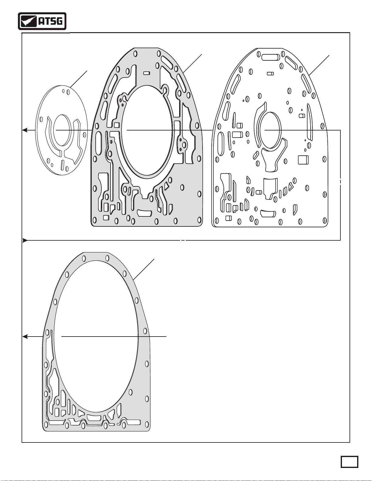
11
Technical Service Information
OIL PUMP ASSEMBLY EXPLODED VIEW
910
1
1. PUMP SPACER PLATE TO CASE GASKET.
2. C1/C2 SEALING RINGS (3 REQUIRED).
3. PUMP COVER TO C1/C2 CLUTCH HOUSING THRUST WASHER.
4. CAGED NEEDLE BEARING ASSEMBLY.
5. PUMP COVER/PUMP BODY BOLTS, M8 x 1.25 x 55 (5 REQUIRED).
6. PUMP COVER ASSEMBLY.
7. PUMP STATOR SHAFT SEAL RING (LARGE).
8. PUMP STATOR SHAFT SEAL RING (SMALL).
9. PUMP SPACER PLATE.
10. PUMP SPACER PLATE TO BELL HOUSING GASKET.
11. PUMP WEAR PLATE.
12. INNER OIL PUMP GEAR.
13. OUTER OIL PUMP GEAR.
14. PUMP BODY TO PUMP COVER DOWEL PINS (2 REQUIRED).
15. OIL PUMP BODY ASSEMBLY .
16. OIL PUMP BODY/CONVERTER HUB BUSHING.
17. OIL PUMP BODY METAL CLAD SEAL.
18. PUMP BODY TO BELL HOUSING SEAL RING.
Figure 86
AUTOMATIC TRANSMISSION SERVICE GROUP
Copyright © 2000 ATSG
59
Page 60

Technical Service Information
CONTINUED FROM PAGE 57
10. Install new front pump body bushing into the
pump body as necessary, using proper bushing
driver (See Figure 88).
11. Install a new front pump body metal clad seal
into pump body using the proper seal driver.
Refer to Figure 88.
12. Install new pump body to bell housing "O" ring
seal in pump body groove, and lubricate using
a small amount of TransJelä. (See Figure 88).
13. Lubricate the inner and outer pump gears with
transmission fluid and install in the pump body
with marks facing up, as shown in Figure 87.
14. Install the two dowel pins into the pump body,
if they were removed, as shown in Figure 88.
15. Assemble the valves, springs, bore plugs and
retainers into the pump cover exactly as they
are shown in Figure 89.
Note: Lubricate all valves in the pump cover
Copyright © 2000 ATSG
with LubeGard® spray lubricant.
Figure 87
18
17
OIL PUMP ASSEMBLY
16
Continued on Page 62
15
14
13
12
12. INNER OIL PUMP GEAR.
13. OUTER OIL PUMP GEAR.
14. PUMP BODY TO PUMP COVER DOWEL PINS (2 REQUIRED).
15. OIL PUMP BODY ASSEMBLY .
16. OIL PUMP BODY/CONVERTER HUB BUSHING.
17. OIL PUMP BODY METAL CLAD SEAL.
18. PUMP BODY TO BELL HOUSING SEAL RING.
60
AUTOMATIC TRANSMISSION SERVICE GROUP
14
Copyright © 2000 ATSG
Figure 88
Page 61

Technical Service Information
OIL PUMP COVER ASSEMBLY
VALVE AND SPRING IDENTIFICATION
Spring Diameter = .635"
5
Free Length = 1.068"
Number Coils = 8
Spring Diameter = .380"
Wire Diameter = .025"
1
Free Length = 1.388"
Number Coils = 7
Wire Diameter = .055"
2
Free Length = 2.825"
Spring Diameter = .890"
Wire Diameter = .108"
3
Number Coils = 11
6
4
7
8
Spring Diameter = .535"
12 13
1. CONVERTER FLOW VALVE.
2. CONVERTER FLOW VALVE SPRING.
3. CONVERTER FLOW VALVE STOP.
4. CONVERTER FLOW VALVE STOP RETAINING PIN.
5. MAIN PRESSURE REGULATOR VAL VE.
6. MAIN PRESSURE REGULATOR VAL VE SPRING.
7. PRESSURE REGULATOR VAL VE STOP.
8. PRESSURE REGULATOR VAL VE STOP RETAINING PIN.
9. CLUTCH BACKFILL VALVE.
10. CLUTCH BACKFILL VALVE SPRING.
Free Length = 1.980"
Number Coils = 12
Wire Diameter = .055"
10
9
14
11. CLUTCH BACKFILL VALVE RETAINER .
12. CONVERTER RELIEF VALVE.
13. CONVERTER RELIEF VALVE SPRING.
14. CONVERTER RELIEF VALVE SPRING RETAINER.
15. LUBE REGULATOR VALVE.
16. LUBE REGULATOR VALVE SPRING.
17. LUBE REGULATOR VALVE SPRING STOP.
18. LUBE REGULATOR VALVE STOP "O" RING.
19. LUBE REGULATOR VALVE STOP RETAINING PIN.
11
Free Length = 1.400"
Number Coils = 7
Spring Diameter = .635"
Wire Diameter = .055"
15
16
17 18
Copyright © 2000 ATSG
19
Figure 89
AUTOMATIC TRANSMISSION SERVICE GROUP
61
Page 62

Technical Service Information
CONTINUED FROM PAGE 60
16. Install the C1/C2 clutch drum thrust washer on
the pump cover and retain with a small amount
of TransJelä (See Figure 90).
17. Install three new C1/C2 clutch drum sealing
rings as shown in Figure 90.
Note: Ensure that the sealing rings will rotate
freely in the ring grooves (See Figure 90).
18. Install two new sealing rings onto the stator
shaft in their proper grooves (See Figure 90).
Note: Ensure that the sealing rings will rotate
freely in their ring grooves (See Figure 90
19. Inspect the caged needle bearing and replace
as necessary (See Figure 90).
20. Place the completed oil pump cover assembly
on a flat work surface with the stator shaft
facing up, as shown in Figure 91.
21. Install the bell housing to pump cover spacer
plate onto the pump cover (See Figure 91).
22. Install the spacer plate to bell housing gasket
on top of the spacer plate (See Figure 91).
23. Install the oil pump wear plate on top of spacer
plate, as shown in Figure 91.
24. Install the pre-assembled oil pump assembly on
top of the wear plate as shown in Figure 92.
Continued on Page 64
8
1. PUMP SPACER PLATE TO CASE GASKET.
2. C1/C2 SEALING RINGS (3 REQUIRED).
3. PUMP COVER TO C1/C2 CLUTCH HOUSING THRUST WASHER.
4. CAGED NEEDLE BEARING ASSEMBLY.
5. PUMP COVER/PUMP BODY BOLTS, M8 x 1.25 x 55 (5 REQUIRED).
6. PUMP COVER ASSEMBLY.
7. PUMP STATOR SHAFT SEAL RING (LARGE).
7
6
5
9.8
4
9.8
4
9.8
3
2
Copyright © 2000 ATSG
62
Figure 90
AUTOMATIC TRANSMISSION SERVICE GROUP
Page 63

OIL PUMP
WEAR PLATE
Technical Service Information
SPACER PLATE TO
BELL GASKET
OIL PUMP
ASSEMBLY
BELL HOUSING
SPACER PLATE
2
9
5
3
1
0
3
1
OIL PUMP COVER
ASSEMBLY
Copyright © 2000 ATSG
Figure 91 Figure 92
AUTOMATIC TRANSMISSION SERVICE GROUP
63
Page 64

Technical Service Information
29536810
PUMP COVER TO
OIL PUMP
RETAINING BOLTS
29536681
2
26
20E9
CONTINUED FROM PAGE 62
25. Install the 5 required pump cover to oil pump
bolts, size identified in Figure 95 and location
is identified in Figure 93, and torque the bolts
to 27 Nm (20 ft.lb.).
26. Assemble the completed oil pump and cover
assembly to the bell housing (See Figure 94).
Note: There are currently four different bell
housings available. Refer to Figures 98 & 99
for the various models.
27. Install the 10 required bell housing to pump
cover bolts, size identified in Figure 95 and
location is identified in Figure 96, and torque
the bolts to 43 Nm (32 ft.lb.).
Note: Notice in Figure 95 that these 10 bolts
have a required seal on the bolt. Ensure that
new seals are installed.
28. Set completed bell housing and pump assembly
aside for the final assembly process, as shown
in Figure 97.
PUMP COVER TO
OIL PUMP
RETAINING BOLTS
Copyright © 2000 ATSG
Figure 93
OIL PUMP AND BELL HOUSING ASSEMBLY
9.8
9.8
9.8
9.8
BELL HOUSING ASSEMBLY
(4 DIFFERENT VERSIONS)
64
BELL HOUSING TO
SPACER PLATE GASKET
OIL PUMP AND PUMP
COVER ASSEMBLY
Figure 94
AUTOMATIC TRANSMISSION SERVICE GROUP
Copyright © 2000 ATSG
Page 65

Technical Service Information
13mm Head
Pump Cover To
Oil Pump (5 Req)
M8 X 1.25 X 55
Bolts Drawn Actual Size
15 mm Head
SEAL
Bell Housing To
Pump Cover (10 Req)
M10 X 1.5 X 50
1
3
0
3
5
9
1
2
Figure 96Figure 95
COMPLETED BELL HOUSING AND PUMP ASSEMBLY
CAUTION: THERE ARE FOUR DIFFERENT
BELL HOUSING CONFIGURATIONS
REFER TO FIGURES 98 AND 99
2
9
5
3
1
0
3
1
Figure 97
AUTOMATIC TRANSMISSION SERVICE GROUP
Copyright © 2000 ATSG
65
Page 66

Technical Service Information
SAE NUMBER 3 BELL HOUSING
WITH INTEGRAL FILTER AND
COOLER PORTS
SAE NUMBER 3 BELL HOUSING
WITH MANIFOLD FOR FILTER
AND COOLER PORTS
9
7
6
3
2
1
1. MAIN CONTROL FILTER ASSEMBLY .
2. MAIN CONTROL FILTER MAGNET.
3. MAIN CONTROL FILTER ADAPTER TUBE.
4. MAIN LINE PRESSURE TAP PLUG.
5. MAIN LINE PRESSURE PLUG "O" RING.
6. TO COOLER SHIPPING PLUG.
7. TO COOLER SHIPPING PLUG "O" RING.
8. FROM COOLER SHIPPING PLUG.
9. FROM COOLER SHIPPING PLUG "O" RING.
10. COOLER MANIFOLD RETAINING BOLT, M8 x 1.25 x 30 (8 REQ).
11. COOLER MANIFOLD RETAINING BOLT, M8 x 1.25 x 40 (4 REQ).
5
4
8
11
10
9
7
6
3
2
1
5
4
Copyright © 2000 ATSG
8
66
Figure 98
AUTOMATIC TRANSMISSION SERVICE GROUP
Page 67

Technical Service Information
SAE NUMBER 2 BELL HOUSING
WITH MANIFOLD FOR FILTER
AND COOLER PORTS
SAE NUMBER 8 BELL HOUSING
WITH INTEGRAL FILTER AND
COOLER PORTS
11
13
3
2
1
10
1. MAIN CONTROL FILTER ASSEMBLY .
9
7
6
3
2
1
5
4
8
2. MAIN CONTROL FILTER MAGNET.
3. MAIN CONTROL FILTER ADAPTER TUBE.
4. MAIN LINE PRESSURE TAP PLUG.
5. MAIN LINE PRESSURE PLUG "O" RING.
6. TO COOLER SHIPPING PLUG.
7. TO COOLER SHIPPING PLUG "O" RING.
8. FROM COOLER SHIPPING PLUG.
9. FROM COOLER SHIPPING PLUG "O" RING.
10. COOLER MANIFOLD RETAINING BOLT, M8 x 1.25 x 30 (8 REQ).
11. COOLER MANIFOLD RETAINING BOLT, M8 x 1.25 x 40 (4 REQ).
12. TO COOLER CONNECTOR FITTING ASSEMBLY.
13. FROM COOLER CONNECTOR FITTING ASSEMBLY.
Copyright © 2000 ATSG
12
5
4
Figure 99
AUTOMATIC TRANSMISSION SERVICE GROUP
67
Page 68

Technical Service Information
C1/C2 CLUTCH HOUSING EXPLODED VIEW
12
1
13 14
2
15 16
3
17
18
4
19
68
28
27
29
LEGEND FOR FIGURES 100 AND 101 FOUND ON PAGE 70
Figure 100
AUTOMATIC TRANSMISSION SERVICE GROUP
31
30
Copyright © 2000 ATSG
Page 69

Technical Service Information
20
5
6
21
7
8
22
9
10
24
11
25
26
C1/C2 CLUTCH HOUSING EXPLODED VIEW
32
34
33
LEGEND FOR FIGURES 100 AND 101 FOUND ON PAGE 70
Figure 101
AUTOMATIC TRANSMISSION SERVICE GROUP
23
35
37
36
Copyright © 2000 ATSG
69
Page 70

Technical Service Information
LEGEND FOR FIGURES 100 AND 101
1. TURBINE SHAFT SEAL RINGS (2 REQUIRED).
2. TURBINE SHAFT ASSEMBLY.
3. C1/C2 CLUTCH HOUSING ASSEMBLY .
4. TURBINE SHAFT RETAINING SNAP RING.
5. C2 CLUTCH PISTON BALANCE "D" RING SEAL.
6. C2 CLUTCH PISTON OUTER "D" RING SEAL.
7. C2 CLUTCH PISTON.
8. C2 CLUTCH PISTON INNER LIP SEAL.
9. C2 CLUTCH PISTON RETURN SPRING ASSEMBLY .
10. C1 CLUTCH HOUSING "O" RING SEAL.
11. C1 CLUTCH HOUSING ASSEMBLY .
12. C1 CLUTCH HOUSING RETAINING SNAP RING.
13. C2 CLUTCH BALANCE PISTON ASSEMBLY (MOULDED).
14. C2 CLUTCH BALANCE PISTON RETAINING SNAP RING.
15. C1 CLUTCH PISTON OUTER "D" RING SEAL.
16. C1 CLUTCH PISTON ASSEMBLY .
17. C1 CLUTCH PISTON INNER TEFLON LIP SEAL (iNNER LIP).
18. C1 CLUTCH PISTON RETURN SPRING ASSEMBLY .
19. C1 CLUTCH PISTON RETURN SPRING SNAP RING.
C2 CLUTCH PISTON
INNER LIP SEAL
C2 CLUTCH
PISTON
C2 PISTON BALANCE
"D" RING SEAL
C2 PISTON OUTER
"D" RING SEAL
20. C1 CLUTCH BALANCE PISTON ASSEMBLY (MOULDED).
21. C1 CLUTCH BALANCE PISTON RETAINING SNAP RING.
22. C1 CLUTCH STEEL PLATES, INTERNAL SPLINE (6 REQUIRED).
23. C1 CLUTCH LINED PLATES, EXTERNAL SPLINE (6 REQUIRED).
24. C1 CLUTCH BACKING PLATE (SELECTIVE).
25. C1 CLUTCH BACKING PLATE SNAP RING (EXTERNAL).
26. C1 CLUTCH BACKING PLATE SPIRAL SNAP RING (INTERNAL).
27. TURBINE SHAFT/C1 CLUTCH HUB THRUST BEARING.
28. C1 CLUTCH HUB ASSEMBLY .
29. C1 CLUTCH HUB/C2 CLUTCH HUB THRUST BEARING.
30. C2 CLUTCH STEEL PLATES (7 REQUIRED).
31. C2 CLUTCH LINED PLATES (6 REQUIRED).
32. C2 CLUTCH HUB ASSEMBLY .
33. C2 CLUTCH HUB/INPUT SUN GEAR THRUST WASHER.
34. INPUT SUN GEAR ASSEMBLY.
35. INPUT SUN GEAR/P1 PLANETARY CARRIER THRUST BEARING.
36. P1 PLANETARY DRIVE FLANGE.
37. P1 PLANETARY DRIVE FLANGE RETAINING SNAP RING.
Figure 102
COMPONENT REBUILD (Cont'd)
C1/C2 CLUTCH HOUSING
1. Disassemble the C1/C2 clutch housing using
Figures 100 and 101 as a guide.
2. Remove and discard all "O" rings, "D" rings
and lip seals (See Figures 100 and 101).
3. Inspect all C1/C2 clutch housing parts for any
wear and/or damage.
4. Clean all C1/C2 housing parts thoroughly, and
dry with compressed air.
5. If turbine shaft was not removed, it should be
removed at this time, as it makes the assembly
of the C1/C2 clutch housing much easier.
6. Install the C2 clutch piston inner lip seal with
the lip facing direction shown in Figure 103.
7. Install the C2 clutch piston balance "D" ring
seal into the piston groove (See Figure 103).
8. Install the C2 clutch piston outer "D" ring seal
into the lower piston groove (See Figure 103).
9. Lubricate all three C2 clutch piston seals with
a small amount of TransJelä.
10. Install the C2 clutch piston and seals into the
C1/C2 clutch housing as shown in Figure 105.
Note: Care should be used during assembly
so as not to damage piston seals.
11. Install the C2 piston return spring assembly on
top of the C2 piston in the housing, as shown
in Figure 105.
70
Copyright © 2000 ATSG
Figure 103
AUTOMATIC TRANSMISSION SERVICE GROUP
Page 71

Technical Service Information
C1 CLUTCH HOUSING
SNAP RING
C1 CLUTCH HOUSING
SNAP RING
C1 CLUTCH
HOUSING
C1 CLUTCH HOUSING
"O" RING SEAL
C1 CLUTCH HOUSING
"O" RING SEAL
C2 CLUTCH RETURN
SRING ASSEMBLY
Copyright © 2000 ATSG
Figure 104
12. Install the C1 clutch housing "O" ring seal into
the lower groove in the C1/C2 clutch housing,
as shown in the cut-away in Figure 104.
13. Lubricate the installed "O" ring seal and inside
diameter of the C1 clutch housing with a small
of TransJelä, and install the C1 clutch housing
as shown in Figure 105.
14. Compress the C1 clutch housing against the
return spring assembly and install the C1 clutch
housing snap ring into the upper groove in the
C1/C2 clutch housing, as shown in cut-away in
Figure 104.
Note: Refer to Figure 106 for snap ring I.D.
for all snap rings in the C1/C2 housing.
C2 CLUTCH
PISTON AND SEALS
C1/C2 CLUTCH
HOUSING
Continued on Page 73
AUTOMATIC TRANSMISSION SERVICE GROUP
Copyright © 2000 ATSG
Figure 105
71
Page 72

Technical Service Information
SNAP RING IDENTIFICATION CHART FOR C1/C2 CLUTCH HOUSING
Snap Ring Number 1 = .090" Thick, Largest Diameter "Eyelet" Snap Ring.
(C1 Clutch Housing Retaining Snap Ring)
Snap Ring Number 2 = .079" Thick, Approximate 3-3/16" Diameter.
(C1 Clutch Piston Return Spring Retaining Snap Ring)
Snap Ring Number 3 = .079" Thick, Approximate 6-1/2" Diameter.
(C1 Clutch Balance Piston Retaining Snap Ring)
Snap Ring Number 4 = .092" Thick, Approximate 8-3/8" Diameter, Same as Snap Ring Number 8.
(C2 Clutch Balance Piston Retaining Snap Ring)
Snap Ring Number 5 = .090" Thick, Smallest Diameter "Eyelet" Snap Ring.
(Turbine Shaft Retaining Snap Ring)
Snap Ring Number 6 = .078" Thick, Approximate 2-7/8" Diameter.
(C1 Clutch Backing Plate Retaining Snap Ring)
Snap Ring Number 7 = "Spiral" Snap Ring, Approximate 3-1/4" Diameter.
(C1 Clutch Backing Plate Snap Ring, "Spiral" Retaining Snap Ring)
Snap Ring Number 8 = .092" Thick, Approximate 8-3/8" Diameter, Same as Snap Ring Number 4.
(C2 Clutch Backing Plate Retaining Snap Ring)
Snap Ring
No. 8
Snap Ring
No. 7
Snap Ring
No. 6
Snap Ring
No. 5
Snap Ring
No. 4
Snap Ring
No. 3
72
Snap Ring
No. 2
Snap Ring
No. 1
Copyright © 2000 ATSG
Figure 106
AUTOMATIC TRANSMISSION SERVICE GROUP
Page 73

Technical Service Information
CONTINUED FROM PAGE 71
15. Install new C1 clutch piston inner lip seal, as
shown in Figure 107.
Note: This seal is hard plastic and difficult to
remove. If the inner lip seal is good, leave it
alone and re-use it, or replace as necessary.
16. Install new C1 clutch piston outer "D" ring seal
in piston groove, as shown in Figure 107.
17. Lubricate both the seals with a small amount of
TransJel®, and install piston into the C1 clutch
housing, as shown in Figure 108.
18. Install C1 clutch piston return spring assembly
onto the C1 clutch piston (See Figure 108).
19. Compress the return spring and install the snap
ring into the groove ensuring that it is properly
seated (See Figure 108).
Note: This snap ring is also difficult to install.
Use the proper tools and refer to Figure 106
for snap ring identification.
C1 CLUTCH HOUSING
SNAP RING
C1 CLUTCH HOUSING
RETURN SPRING ASM.
C1 CLUTCH PISTON
INNER SEAL
C1 CLUTCH
PISTON
C1 CLUTCH PISTON
OUTER "D" RING
Continued on Page 74
C1 CLUTCH
PISTON AND SEALS
C1/C2 CLUTCH
HOUSING
Figure 108Figure 107
AUTOMATIC TRANSMISSION SERVICE GROUP
Copyright © 2000 ATSGCopyright © 2000 ATSG
73
Page 74

Technical Service Information
CONTINUED FROM PAGE 73
20. Lubricate the molded C1 clutch balance piston
with small amount of TransJel®, and install in
C1/C2 clutch housing (See Figure 109).
Note: Replace balance piston as necessary.
21. Install the C1 clutch balance piston snap ring
as shown in Figure 109, and ensure that it is
fully seated (See Figure 109).
22. Lubricate the molded C2 clutch balance piston
with small amount of TransJel®, and install in
C1/C2 clutch housing (See Figure 109).
Note: Replace balance piston as necessary.
23. Install the C2 clutch balance piston snap ring
as shown in Figure 109, and ensure that it is
fully seated (See Figure 109).
C2 CLUTCH
BALANCE PISTON
SNAP RING
C1 CLUTCH
BALANCE PISTON
SNAP RING
TURBINE SHAFT
SNAP RING
C1/C2 CLUTCH
HOUSING ASM.
C2 CLUTCH
BALANCE PISTON
TURBINE SHAFT
ASSEMBLY
74
C1 CLUTCH
BALANCE PISTON
TURBINE SHAFT
SEALING RINGS
Copyright © 2000 ATSGCopyright © 2000 ATSG
Figure 109 Figure 110
AUTOMATIC TRANSMISSION SERVICE GROUP
Page 75

Technical Service Information
24. Install two new sealing rings onto turbine shaft
as shown in Figure 110.
25. Now install the turbine shaft into the splines of
the C1/C2 clutch housing and install the eyelet
snap ring in bottom groove (See Figure 110).
Note: This is the smaller of the 2 eyelet snap
rings in this housing. Refer to Figure 106 for
positive snap ring identification.
26. Install C1 clutch pack beginning with a steel
plate, and alternating with a lined plate until
you have installed 6 required steel plates and
6 required lined plates (See Figure 111).
Note: Notice that the steel plates have internal
teeth and the lined plates have external teeth.
27. Install the C1 clutch backing plate in housing
in the direction shown in Figure 111, and make
sure that it is fully seated.
28. Install the external C1 clutch backing plate
snap ring as shown in Figure 111.
Note: The Spiral snap ring must be removed
from the backing plate to install the external
snap ring. Refer to Figure 106 for positive
snap ring identification.
29. After the external backing plate snap ring has
been installed, now install the "Spiral" snap
ring on the inside groove of backing plate, as
shown in Figure 111.
Note: The Spiral snap ring must be installed
in backing plate to retain the external snap
from possibly coming off from centrifugal
force. Refer to Figure 106 for positive I.D. of
snap rings in C1/C2 housing.
C1 CLUTCH
"SPIRAL"
SNAP RING
C1 CLUTCH
BACKING PLATE
SNAP RING
C1 CLUTCH
BACKING PLATE
C1 STEEL
PLATES
(6 REQ.)
C1 LINED
PLATES
(6 REQ.)
Continued on Page 76
AUTOMATIC TRANSMISSION SERVICE GROUP
C1/C2 CLUTCH
HOUSING ASSEMBLY
Copyright © 2000 ATSG
Figure 111
75
Page 76

C1 CLUTCH HUB TO
C2 CLUTCH HUB
THRUST BEARING
C1 CLUTCH HUB
TURBINE SHAFT TO
C1 CLUTCH HUB
THRUST BEARING
Technical Service Information
CONTINUED FROM PAGE 75
30. Install dial indicator onto C1/C2 clutch housing
as shown in Figure 112, with indicator indexed
against the C1 selective backing plate, and set
the dial to zero.
31. Lift up on both sides of C1 clutch pack until
the selective backing plate is against the snap
ring, and record dial indicator reading.
Note: C1 clutch clearance is .105" - .125".
32. Change the C1 backing plate as necessary to
obtain correct clutch clearance.
33. Install the turbine shaft/C1 clutch hub thrust
bearing assembly onto the turbine shaft in the
direction shown in Figure 112.
34. Install the C1 clutch hub over the external teeth
of the lined plates, in a twisting back and forth
motion until fully seated (See Figure 112).
35. Install the C1 clutch hub/C2 clutch hub thrust
bearing assembly onto the C1 clutch hub in the
direction shown in Figure 112.
36. Install the C2 clutch hub over C1 clutch hub, as
shown in Figure 113.
37. Install C2 clutch hub to input sun gear thrust
washer, ensuring that tabs are engaged into the
slots on C2 clutch hub, as shown in Figure 113
CHECKING C1 CLUTCH CLEARANCE
Clearance Should Be .105" - .125"
0
1010
2020
3030
4040
5050
0
INDICATOR
DIAL
76
Copyright © 2000 ATSG
Figure 112
AUTOMATIC TRANSMISSION SERVICE GROUP
Page 77

Technical Service Information
38. Install the C2 clutch pack into the housing, as
shown in Figure 114, beginning with a steel
plate and alternating with lined plates until you
have installed 7 steel plates and 6 lined plates.
Note: In the C2 clutch pack you begin with a
steel plate and end with a steel plate as shown
in Figure 114.
Continued on Page 78
C2 CLUTCH HUB TO
INPUT SUN GEAR
THRUST WASHER
C2 CLUTCH
HUB
C2
STEEL
PLATES
C2
LINED
PLATES
Copyright © 2000 ATSG Copyright © 2000 ATSG
Figure 113
AUTOMATIC TRANSMISSION SERVICE GROUP
Figure 114
77
Page 78

P1 PLANETARY
DRIVE FLANGE
P1 PLANETARY
(INPUT) SUN GEAR
Technical Service Information
CONTINUED FROM PAGE 76
36. Install the P1 planetary drive flange snap ring
into the lower groove in the clutch housing, as
shown in Figure 117.
37. Check the C2 clutch clearance using a feeler
gage, as shown in Figure 117.
Note: Correct C2 clutch clearance should be
.060" - .085" (See Figure 117). There are no
selectives for C2 clutch. If the clearance is
P1 PLANETARY
DRIVE FLANGE
SNAP RING
WIDE
TOOTH
not correct, there is a mis-assembly.
38. Remove the P1 planetary drive flange snap ring
from the lower groove in the clutch housing.
39. Install P1 planetary (Input) sun gear through
the P1 planetary drive flange from the bottom
as shown in Figures 115 and 116.
40. Holding the assembly by the sun gear, install
the sun gear and drive flange assembly into the
C1/C2 housing engaging the drive flange teeth
into the splines of housing (See Figure 115).
Note: Notice that drive flange has three wide
teeth that must be indexed to 3 wide grooves
in the housing (See Figure 115).
41. Install the P1 planetary drive flange snap ring
into top groove in housing (See Figure 115).
Note: Refer to Figure 106 for C1/C2 clutch
housing snap ring identification as necessary.
78
P1 SUN GEAR AND DRIVE FLANGE ASSEMBLED
P1 PLANETARY
(INPUT) SUN GEAR
P1 PLANETARY
DRIVE FLANGE
Copyright © 2000 ATSG Copyright © 2000 ATSG
Figure 115 Figure 116
AUTOMATIC TRANSMISSION SERVICE GROUP
Page 79

Technical Service Information
42. Install the P1 sun gear to P1 planetary carrier
thrust bearing onto the sun gear in the direction
shown in Figure 118, and retain with a small
amount of TransJel®.
43. Set completed C1/C2 Clutch Housing assembly
aside for the final assembly process. Refer to
Figure 118.
"COMPONENT REBUILD"
Continued on Page 82
CHECKING C2 CLUTCH CLEARANCE
Clearance should be .060" - .085"
P1 SUN GEAR TO
P1 PLANETARY CARRIER
THRUST BEARING
COMPLETED
C1/C2 CLUTCH
HOUSING
Copyright © 2000 ATSG Copyright © 2000 ATSG
Figure 117
AUTOMATIC TRANSMISSION SERVICE GROUP
Figure 118
79
Page 80

Technical Service Information
ALLISON SERIES 1000/2000 COMPLETE VALVE BODY
Accumulator
Valve Springs
Accumulator
Valves
Retainer Assembly
80
PRESSURE SWITCH
ASSEMBLY
Shift Solenoid "E"
(Normally Closed)
Trim Solenoid "B"
(Normally Open)
Trim Solenoid "A"
(Normally Closed)
Shift Solenoid "C"
(Normally Closed)
Figure 119
AUTOMATIC TRANSMISSION SERVICE GROUP
TCC Solenoid "F"
(N/C PWM)
Shift Solenoid "D"
(Normally Closed)
Copyright © 2000 ATSG
Page 81

"Shift" Valve body
(See Figure 124)
Spacer Plate
"Main" Valve body
(See Figure 123)
Technical Service Information
Internal Wire
Harness Asm.
5
4
1. PRESSURE SWITCH ASSEMBLY .
2. REVERSE SIGNAL PIPE ASSEMBLY.
3. VALVE BODY TO VALVE BOD Y BOLT , M6 X 1.0 X 65 (1 REQUIRED).
4. VALVE BODY TO VALVE BOD Y BOLT , M6 X 1.0 X 50 (23 REQUIRED).
5. VALVE BODY TO CASE BOLTS, M6 X 1.0 X 50 (15 REQUIRED).
Figure 120
1
2
3
Copyright © 2000 ATSG
AUTOMATIC TRANSMISSION SERVICE GROUP
81
Page 82

Technical Service Information
COMPONENT REBUILD (Cont'd)
VALVE BODY ASSEMBLY
1. Disassemble the valve body assembly, using
Figures 119 and 120 as a guide.
2. Remove the two bolts retaining the reverse
pipe, and remove the reverse pipe from valve
body assembly (See Figure 121).
Note: Notice the manual valve pin, as shown
in Figure 121. This pin can fall out and not
be noticed. Remove it now and place in safe
place until reassembly.
3. Remove the wire connector from the pressure
switch assembly and all six solenoids as shown
in Figure 119.
4. Remove the two solenoid retaining clips from
valve body, shown in Figure 121 and remove
the internal wire harness assembly.
5. Remove the three bolts from the trim solenoid
retaining bracket and remove the bracket, as
shown in Figure 119.
6. Remove the two trim solenoids using caution
so that valve trains behind them do not come
out at this time.
Note: Notice that Trim Solenoid "A" has a
green "O" ring, and Trim Solenoid "B" has a
black "O" ring. The snout diameters are also
different, .645" for "A" and .665" for "B".
Refer to Figure 122.
7. Air checks and resistance readings for all of the
solenoids are provided in Figure 122, that can
be performed now to determine if replacement
is necessary.
Note: Air checks should be made on fixture
with 40 PSI regulated air pressure.
Continued on Page 86
VALVE BODY ASSEMBLY
Internal Wiring Harness retained with
these two solenoid retaining clips.
Remove Reverse Pipe.
D
u
Pa
g
e
82
CAUTION: This manual valve pin is easily lost, as it may fall out un-noticed.
Copyright © 2000 ATSG
Figure 121
AUTOMATIC TRANSMISSION SERVICE GROUP
Page 83

Technical Service Information
SOLENOID AIR CHECKS
TRIM SOLENOID "A"
(Normally Closed)
Snout
Diameter
= .645"
Blow Air
In Here
De-energized = No Air Here
Energized = Air Here
Blow Air
In Here
Green
"O" Ring
5.5 - 8.0 W
@ 72°F
Snout
Diameter
= .665"
Blow Air
In Here
SHIFT SOLENOIDS "C", "D" AND "E"
20 - 30 W
@ 72°F
Blow Air
In Here
TRIM SOLENOID "B"
(Normally Open)
Black
"O" Ring
De-energized = Air Here
Energized = No Air Here
5.5 - 8.0 W
@ 72°F
De-energized = Air Exits Here
Blow Air
In Here
Energized = Air Exits Here
Energized = Air Exits Here
LOCK-UP SOLENOID "F"
8 - 15 W
@ 72°F
De-energized = Air Exits Here
Copyright © 2000 ATSG
Figure 122
AUTOMATIC TRANSMISSION SERVICE GROUP
83
Page 84

Technical Service Information
"MAIN" VALVE BODY EXPLODED VIEW
1. MAIN VALVE BODY CASTING.
2. ALIGNMENT DOWELS (5 REQUIRED).
3. MAIN CONTROL RELIEF VALVE.
4. MAIN CONTROL RELIEF VALVE SPRING.
5. MAIN CONTROL RELIEF VALVE SPRING RETAINER.
6. EXHAUST BACKFILL VALVE SPRING RETAINER.
7. EXHAUST BACKFILL VALVE SPRING.
8. EXHAUST BACKFILL VALVE.
9. BOLT, M6 X 1.0 X 50 (23 REQUIRED)
10. SOLENOID "F" TRIM VALVE SPRING.
11. SOLENOID "F" TRIM VALVE.
12. SOLENOID "F" TRIM VALVE SLEEVE.
13. SOLENOID "F" SMALL "O" RING.
5
4
6
8
7
Free Length = .875"
Number Coils = 11
Spring Diameter = .490"
Wire Diameter = .034"
Free Length = 1.690"
Number Coils = 13
Spring Diameter = .550"
Wire Diameter = .058"
3
14. SOLENOID "F" LARGE "O" RING.
15. SOLENOID "F" (LOCK-UP PWM).
16. SOLENOID "F" RETAINING CLIP .
17. SHIFT SOLENOID "D" SMALL "O" RING.
18. SHIFT SOLENOID "D" LARGE "O" RING.
19. SHIFT SOLENOID "D".
20. SHIFT SOLENOID "D" RETAINING CLIP .
21. SHIFT SOLENOID "E" SMALL "O" RING.
22. SHIFT SOLENOID "E" LARGE "O" RING.
23. SHIFT SOLENOID "E".
24. TRIM PRESSURE ACCUMULATORS.
25. TRIM PRESSURE ACCUMULATOR SPRINGS.
26. TRIM SOLENOID "A" AND "B" RETAINING BRACKET.
27. TRIM "B" VALVE SPRING.
28. TRIM "B" VALVE.
29. TRIM GAIN VALVE.
30. TRIM SOLENOID "B" "O" RING (BLACK).
31. TRIM SOLENOID "B" (N/O PWM) (Snout Diameter = .665").
2
1
32. TRIM SOLENOID "A" (N/C PWM) (Snout Diameter = .645").
33. TRIM SOLENOID "A" "O" RING (GREEN).
34. TRIM GAIN VALVE.
35. TRIM "A" VALVE (Note I.D. Ring Between Lands).
36. TRIM "A" VALVE SPRING.
Free Length = .845"
Number Coils = 7
Spring Diameter = .384"
Wire Diameter = .028"
36
35
34
27
28
33
32
84
9
Free Length = .838"
Number Coils = 7
Spring Diameter = .382"
Wire Diameter = .028"
10
21
22
23
17
18
11
12
13
19
20
14
15
16
25
26
9
Figure 123
AUTOMATIC TRANSMISSION SERVICE GROUP
24
29
30
31
2
Free Length = 1.275"
Number Coils = 16
Spring Diameter = .306"
Wire Diameter = .043"
Copyright © 2000 ATSG
Page 85

Technical Service Information
"SHIFT" VALVE BODY EXPLODED VIEW
1. SHIFT VALVE BODY CASTING.
2. SOLENOID SCREEN.
3. SHIFT SOLENOID "C".
4. SHIFT SOLENOID "C" RETAINING CLIP .
5. MANUAL SELECTOR VALVE.
6. MANUAL SELECTOR VALVE PIN.
7. SOLENOID "D" SHIFT VALVE.
8. SOLENOID "D" SHIFT VALVE SPRING.
9. SOLENOID "D" SHIFT VALVE BORE PLUG.
10. SOLENOID "D" SHIFT VALVE LINE-UP RETAINER.
11. SOLENOID "E" SHIFT VALVE.
12. SOLENOID "E" SHIFT VALVE SPRING.
13. SOLENOID "E" SHIFT VALVE BORE PLUG.
14. SOLENOID "E" SHIFT VALVE LINE-UP RETAINER.
15. SOLENOID "C" SHIFT VALVE.
16. SOLENOID "C" SHIFT VALVE SPRING.
17. SOLENOID "C" SHIFT VALVE LINE-UP RETAINER.
18. MAIN CONTROL VALVE.
19. MAIN CONTROL VALVE SPRING.
20. MAIN CONTROL VALVE LINE-UP RETAINER.
Free Length = 1.155"
Number Coils = 11
Spring Diameter = .435"
Wire Diameter = .037"
8
9
10
14
19
3
18
4
2
1
5
6
7
12
13
17
11
15
16
20
Free Length = 1.155"
Number Coils = 11
Spring Diameter = .435"
Wire Diameter = .037"
AUTOMATIC TRANSMISSION SERVICE GROUP
Free Length = 1.170"
Number Coils = 11
Spring Diameter = .435"
Wire Diameter = .037"
Figure 124
Free Length = 1.705"
Number Coils = 13
Spring Diameter = .550"
Wire Diameter = .057"
Copyright © 2000 ATSG
85
Page 86

Technical Service Information
CONTINUED FROM PAGE 82
8. Place main valve body on a flat work surface,
remove the valve trains one at a time and lay
them out in order, as shown in Figure 123.
9. Clean and inspect all main valve body parts
thoroughly and dry with compressed air.
10. Assemble the main valve body valve trains
exactly as they are shown in Figure 123.
Note: Notice that the various spring specs
are included in Figure 123, to ensure that
they are installed in their proper locations.
Lubricate all valves in the main valve body
with LubeGard® spray lubricant.
11. Place shift valve body on a flat work surface,
remove the valve trains one at a time and lay
them out in order, as shown in Figure 124.
12. Clean and inspect all shift valve body parts
thoroughly and dry with compressed air.
13. Assemble the shift valve body valve trains
exactly as they are shown in Figure 124.
Note: Notice that the various spring specs
are included in Figure 124, to ensure that
they are installed in their proper locations.
Lubricate all valves in the shift valve body
with LubeGard® spray lubricant.
14. Lay the main valve body on flat work surface
as shown in Figure 126, and install the spacer
plate over the dowel pins.
15. Install the shift valve body on top of the spacer
plate and over dowels, as shown in Figure 126.
16. Turn the entire assembly over on the flat work
surface, as shown in Figure 125.
17. Install only 14, M6 x 1.0 x 50mm, main valve
body to shift valve body bolts in the locations
shown in Figure 125, and snug them down.
Note: Do not tighten at this time.
18. Install both Trim Solenoids "A" and "B" in the
exact locations shown in Figure 127.
Note: The trim solenoids have different snout
dimensions and "O" ring colors, as shown in
Figure 127. Ensure that they are installed in
their proper locations.
19. Install the trim solenoid retaining bracket and
three M6 x 1.0 x 50mm bolts, as shown in
Figure 127, and snug them down.
Note: Do not tighten.
Continued on Page 89
DuPage
29536840
ASSEMBLE SHIFT VALVE BODY TO MAIN VALVE BODY
Install 14 Only, M6 X 1.0 X 50, Main
Valve Body to Shift Valve Body Bolts,
In The Locations Shown Here, and
Snug Them Down. Do Not tighten.
8 mm Head
Actual Size
86
Copyright © 2000 ATSG
Figure 125
AUTOMATIC TRANSMISSION SERVICE GROUP
Page 87

"Shift" Valve body
Spacer Plate
"Main" Valve body
Technical Service Information
DuPage
29536840
Figure 126
ASSEMBLE TRIM SOLENOIDS
Install both Trim Solenoids "A" and "B" in the exact
locations shown below, as they are different. Install the
retaining bracket and 3 M6 x 1.0 x 50 bolts to retain
bracket, and snug down. Do Not tighten.
Trim Solenoids
Retaining Bracket
Trim Solenoid "B", (N/O),
Snout Diameter = .665",
Requires Black "O" Ring.
8 mm Head
Actual Size
Figure 127
AUTOMATIC TRANSMISSION SERVICE GROUP
Trim Solenoid "A", (N/C),
Snout Diameter = .645",
Requires Green "O" Ring.
Copyright © 2000 ATSG
87
Page 88

Technical Service Information
Install the Pressure Switch Assembly
and 5 M6 x 1.0 x 50 retaining Bolts
DuPage
in the locations shown here, and
Snug Them Down. Do Not tighten.
29536840
Pressure Switch Assembly
Figure 128
8 mm Head
Actual Size
Copyright © 2000 ATSG
8 mm Head 8 mm Head
DuPage
29536840
One M6 x 1.0 x 50mm
Reverse Pipe Retaining Bolt.
Reverse Feed Pipe
One M6 x 1.0 x 65mm
Reverse Pipe Retaining Bolt.
Figure 129
Actual Size
Copyright © 2000 ATSG
88
AUTOMATIC TRANSMISSION SERVICE GROUP
Page 89

Technical Service Information
CONTINUED FROM PAGE 86
20. Inspect the pressure switch assembly to verify
the condition and location of the "O" rings on
the back side (See Figure 130).
21. One of the six switches in the pressure switch
assembly is Normally Closed (N/C) and the
other five are Normally Open (N/O), as shown
in Figure 130.
Note: Notice that two of the N.O. switches
are not used in this unit (See Figure 130).
22. Check the operation of all switches with your
DVOM with the leads placed on the pins on
each side of each switch (See Figure 130).
23. To check the resistance values for the TFT
sensor, place the leads of the ohmmeter across
pins "E" and "F" of pressure switch connector.
Note: 3088-3942 Ohms @ 20°C (68°F).
159-198 Ohms @ 100°C (212°F).
24. Install the pressure switch assembly onto the
valve body using five M6 x 1.0 x 50mm bolts,
and installed only in the locations that are
shown in Figure 128, and snug them down.
Note: Do not tighten at this time.
25. Install the reverse pipe onto the valve body, as
shown in Figure 129, using one 50mm long
bolt and one 65mm long bolt in the locations
shown in Figure 129 and snug them down.
Note: Do not tighten at this time.
26. Now torque all valve body bolts to 12 N.m,
(9 ft.lb), beginning in the center and working
outward in a circle (See Figure 129).
Note: Do not over-torque.
Continued on Page 90
"E" SHIFT (N/O)
NOT USED (N/O)
BENCH TESTING PRESSURE SWITCH ASSEMBLY
REVERSE (N/C)
(THERMISTER)
A B C D E F
Pressure Switch Assembly
Receptacle (Face View)
NOT USED (N/O)
TEMP SENSOR
"D" SHIFT (N/O)
"C" SHIFT (N/O)
Pressure Switch
Connector
C
A
NOT USED
D
B
E
C
NOT USED
R
D
E
F
PRESSURE SWITCH
PRESSURE SWITCH
ASSEMBLY
ASSEMBLY
Copyright © 2000 ATSG
TEMP
SENSOR
Figure 130
AUTOMATIC TRANSMISSION SERVICE GROUP
89
Page 90

Technical Service Information
CONTINUED FROM PAGE 89
27. Orient both trim solenoids, TCC solenoid and
shift solenoids with connectors pointed in the
direction shown in Figure 131.
28. Install the internal wiring harness assembly, as
shown in Figure 131, ensuring that connectors
are fully seated and locked.
Note: The wire harness assembly is retained
to the valve body with the two solenoid clips
as shown in Figure 131.
29. Install the manual valve into the valve body
and the manual valve pin, ensuring that the
pin enters the slot in the valve body casting.
Refer to Figure 131.
30. Set the completed valve body assembly aside
for the final assembly process.
Internal Wiring Harness retained with
these two solenoid retaining clips.
MANUAL
VALVE PIN
MANUAL VALVE
D
uP
ag
e
Copyright © 2000 ATSG
90
Figure 131
AUTOMATIC TRANSMISSION SERVICE GROUP
Page 91

Technical Service Information
EXTENSION HOUSING FOR TWO WHEEL DRIVE
ALL MODELS 2WD AND PARKING
BRAKE MODELS
EXTENSION HOUSING FOR MODELS WITH PARKING BRAKE
EXTENSION HOUSING FOR FOUR WHEEL DRIVE
Figure 132
AUTOMATIC TRANSMISSION SERVICE GROUP
Copyright © 2000 ATSG
91
Page 92

Technical Service Information
EXTENSION HOUSING PARTS EXPLODED VIEW
1
2 3 4 5
12
9 10 11
11
13
92
14
Copyright © 2000 ATSG
Figure 133
AUTOMATIC TRANSMISSION SERVICE GROUP
Page 93

Technical Service Information
EXTENSION HOUSING PARTS EXPLODED VIEW
6 7 8
15 16 17 18 19 20 21
1. P-3 PLANETARY CARRIER. (REFERENCE ONLY)
2. CAGED NEEDLE BEARING RETAINING SNAP RING.
3. CAGED NEEDLE BEARING ASSEMBLY.
4. OUTPUT SPEED SENSOR TONE WHEEL (MODEL SENSITIVE).
5. "SELECTIVE" SPACER.
6. C-5 CLUTCH PISTON ASSEMBL Y .
7. C-5 CLUTCH PISTON OUTER "D" RING SEAL.
8. C-5 CLUTCH PISTON INNER LIP SEAL.
9. EXTENSION HOUSING TO CASE GASKET.
10. EXTENSION HOUSING (MODEL SENSITIVE).
11. EXTENSION HOUSING BOLTS, M10 x 1.5 x 40 (16 REQUIRED).
12. OUTPUT SHAFT SPEED SENSOR (MODEL SENSITIVE).
13. OUTPUT SHAFT SPEED SENSOR "O" RING.
14. SPEED SENSOR RETAINING BOLT, M6 x 1.0 x 13.
15. FRETTING RING.
16. BALL BEARING ASSEMBLY.
17. BALL BEARING RETAINING SNAP RING.
18. EXTENSION HOUSING METAL CLAD SEAL (MODEL SENSIITIVE).
19. TRANSMISSIONYOKE ASSEMBLY (MODEL SENSITIVE).
20. YOKE WASHER (MODEL SENSITIVE).
21. YOKE RETAINING BOLT , 1/2"-20 (MODEL SENSITIVE).
Figure 134
AUTOMATIC TRANSMISSION SERVICE GROUP
Copyright © 2000 ATSG
93
Page 94

Technical Service Information
COMPONENT REBUILD (Cont'd)
EXTENSION HOUSING ASSEMBLY
1. Disassemble the extension housing assembly
using Figures 133 and 134 as a guide.
2. Remove and discard the C5 clutch piston seals
from the C5 clutch piston.
3. Inspect all extension housing parts for any wear
and/or damage.
4. Clean all extension housing parts thoroughly
and dry with compressed air.
5. Position the extension housing on a flat work
surface with the rear facing up, as shown in
Figure 135.
6. Install the ball bearing fretting ring into the
extension housing bore (See Figure 135).
7. Install the ball bearing and the retaining snap
ring, as shown in Figure 135.
Note: Ensure the snap ring is fully seated.
8. Install the rear metal clad seal (if used) into the
extension housing, using the proper seal driver
as shown in Figure 135.
9. Turn the extension housing over so the front
side is facing up, as shown in Figure 136.
10. Install the selective spacer against ball bearing
in extension housing (See Figure 136).
11. Install output speed sensor tone wheel (if used)
in the direction shown in Figure 136.
Continued on Page 95
REAR SEAL
ASSEMBLY
BALL BEARING
SNAP RING
BALL BEARING
ASSEMBLY
FRETTING RING
(SPACER)
EXTENSION HOUSING
(MODEL SENSITIVE)
CAGED NEEDLE
BEARING
SNAP RING
CAGED NEEDLE
BEARING
SPEED SENSOR
TONE WHEEL
(MODEL SENSITIVE)
"SELECTIVE"
SPACER
EXTENSION HOUSING
(MODEL SENSITIVE)
94
Copyright © 2000 ATSGCopyright © 2000 ATSG
Figure 135 Figure 136
AUTOMATIC TRANSMISSION SERVICE GROUP
Page 95

C5 CLUTCH PISTON
C5 CLUTCH PISTON
INNER LIP SEAL
Technical Service Information
CONTINUED FROM PAGE 94
12. Install caged needle bearing in the extension
housing bore, as shown in Figure 136.
13. Install the caged needle bearing retaining snap
ring, as shown in Figure 136.
Note: Ensure the snap ring is fully seated.
14. Install the C5 clutch piston inner lip seal into
the piston with the lip facing direction shown
in Figure 137.
15. Install the C5 clutch piston outer "D" ring seal
into the groove in piston (See Figure 137).
16. Lubricate both piston seals, and seal surfaces
in the extension housing with a small amount
of TransJel® (See Figure 137).
17. Install the C5 clutch piston assembly into the
extension housing, using care so as not to cut
or damage the seals (See Figure 137).
18. Set the completed extension housing assembly
aside for the final assembly process.
C5 CLUTCH PISTON
OUTER "D" RING
SEAL
COMPLETED EXTENSION HOUSING ASSEMBLY
EXTENSION HOUSING
(MODEL SENSITIVE)
Copyright © 2000 ATSGCopyright © 2000 ATSG
Figure 137 Figure 138
AUTOMATIC TRANSMISSION SERVICE GROUP
95
Page 96

Technical Service Information
GEAR TRAIN PARTS EXPLODED VIEW
3
1
2
9 10 11
4
96
17
18
2WD Version
4WD Version
Figure 139
AUTOMATIC TRANSMISSION SERVICE GROUP
19
Copyright © 2000 ATSG
Page 97

Technical Service Information
GEAR TRAIN PARTS EXPLODED VIEW
5 6 7
8
12 13 14 15 16
1. INPUT SUN GEAR, P1SUN GEAR (INSTALLED IN C1/C2 HOUSING).
2. INPUT SUN GEAR/P1 PLANETARY CARRIER THRUST BEARING.
3. P1 PLANETARY INTERNAL RING GEAR.
4. P1 RING GEAR/P2 RING GEAR "PEEK" THRUST WASHER.
5. P1 PLANETARY SNAP RING, RET AINS P2 INTERNAL RING GEAR.
6. P1 PLANETARY CARRIER ASSEMBL Y .
7. P2 PLANETARY INTERNAL RING GEAR.
8. P1 PLANETARY CARRIER/P2 PLANETAR Y CARRIER THRUST BEARING.
9. P2 PLANETARY SNAP RING, RET AINS P3 INTERNAL RING GEAR.
10. P2 PLANETARY CARRIER ASSEMBL Y .
11. P3 PLANETARY INTERNAL RING GEAR.
12. TRANSMISSION MAIN SHAFT.
13. P2 PLANETARY CARRIER/P2 SUN GEAR THRUST BEARING.
14. P2 SUN GEAR.
15. SUN GEAR SPACER.
16. P3 SUN GEAR.
17. P3 SUN GEAR/OUTPUT SHAFT THRUST BEARING.
18. OUTPUT SHAFT (MODEL SENSITIVE)..
19. P3 PLANETARY CARRIER ASSEMBL Y .
Copyright © 2000 ATSG
Figure 140
AUTOMATIC TRANSMISSION SERVICE GROUP
97
Page 98

Technical Service Information
COMPONENT REBUILD (Cont'd)
GEAR TRAIN ASSEMBLY
1. Inspect all gear train parts thoroughly, that are
shown in Figures 139 and 140, for any wear
and/or damage.
2. Check all 3 planetary carriers for proper pinion
end play with a feeler gage (See Figure 143).
Note: End play should be .020"-.030".
3. Lay the P2 ring gear (with notches) on a flat
work surface in direction shown in Figure 141.
4. Install the P1 planetary carrier into the splines
of the P2 ring gear, and install the P1 planetary
snap ring, as shown in Figure 141.
P1 PLANETARY
SNAP RING
5. Install the P1/P2 ring gear thrust washer onto
the assembly as shown in Figure 142.
Note: This thrust washer will "Snap" in place
when it is fully seated.
6. Set the completed P1 planetary assembly aside
for final assembly (See Figure 145).
7. Lay the P3 ring gear (no notches) on the flat
work surface in direction shown in Figure 144.
8. Install the P2 planetary carrier into the splines
of the P3 ring gear, and install the P2 planetary
snap ring, as shown in Figure 144.
9. Set the completed P2 planetary assembly aside
for final assembly (See Figure 145).
10. After P3 planetary carrier has been inspected
and correct pinion end play has been verified,
set it aside for final assembly (See Figure 145).
P1 PLANETARY
CARRIER
P2 PLANETARY
RING GEAR
P1/P2 RING GEAR
THRUST WASHER
P1 PLANETARY
CARRIER
ASSEMBLY
98
Copyright © 2000 ATSGCopyright © 2000 ATSG
Figure 141 Figure 142
AUTOMATIC TRANSMISSION SERVICE GROUP
Page 99

P2 PLANETARY
SNAP RING
Technical Service Information
COMPLETED
P1 PLANETARY
AND P2 RING GEAR
Copyright © 2000 ATSG
Figure 143
COMPLETED
P2 PLANETARY
AND P3 RING GEAR
P2 PLANETARY
CARRIER
P3 PLANETARY
RING GEAR
COMPLETED
P3 PLANETARY
Figure 144
AUTOMATIC TRANSMISSION SERVICE GROUP
Copyright © 2000 ATSGCopyright © 2000 ATSG
Figure 145
99
Page 100

Technical Service Information
1
8 9
2
CASE CLUTCH PARTS EXPLODED VIEW
3
4
5
10
100
11
16
17
18
Figure 146
AUTOMATIC TRANSMISSION SERVICE GROUP
Copyright © 2000 ATSG
 Loading...