

Page 1

ALESIS
QuadraVerb GT
Reference Manual
Page 2

sCHAPTER 1 Ð GETTING STARTED ...............................................1
1.1 INTRODUCTION ......................................................................................1
What It Is ...............................................................................................1
Features..................................................................................................2
1.2 SYSTEM HOOKUP BASICS.....................................................................2
AC Transformer Hookup...................................................................3
1.3 AUDIO HOOKUPS ....................................................................................3
Mono In, Mono Out............................................................................3
Mono In, Stereo Out............................................................................4
Stereo In, Stereo Out ...........................................................................4
Mono Send, Mono Return Effects Loop .........................................5
Mono Send, Stereo Return Effects Loop.........................................5
Stereo Send, Stereo Return Effects Loop.........................................6
Interfacing with Mixer Stereo Effects Sends...................................7
1.4 FOOTSWITCH HOOKUP.........................................................................7
1.5 EXTERNAL EFFECTS HOOKUP ............................................................8
1.6 SETTING LEVELS......................................................................................9
1.7 CHECK OUT THE FACTORY PROGRAMS.........................................9
Selecting Programs ..............................................................................10
1.8 MIDI HOOKUP...........................................................................................10
MIDI Program Selection .....................................................................11
MIDI Controller Pedal Hookup ........................................................12
MIDI Thru/Out Hookup....................................................................13
1.9 ROCK OUT!.................................................................................................13
CHAPTER 2 Ð QuadraVerb GT MODULES AND CONFIGURATIONS 14
2.1 ABOUT THE QUADRAVERB GT's EFFECTS ....................................14
Preamp ...................................................................................................14
Reverb....................................................................................................14
Delay .......................................................................................................15
Pitch Change .........................................................................................15
Equalization ..........................................................................................16
Panning and Tremolo.........................................................................18
Ring Modulation .................................................................................18
Tunable Resonators.............................................................................18
Sampling................................................................................................18
Mixer.......................................................................................................18
Modulation...........................................................................................19
ÒBi-TimbralÓ Effects.............................................................................19
2.2 ABOUT CONFIGURATIONS.................................................................20
#1 Preamp > EQ > Tremolo/Panning > Pitch > Delay > Reverb 21
#2 Preamp > Lezlie > Delay > Reverb.............................................22
#4 Preamp > 5 Band EQ > Tremolo/Panning >............................23
Page 3

#5 Preamp > 3 Band EQ > Reverb....................................................24
#6 Preamp > Ring Modulator > Delay > Reverb..........................25
#7 Preamp > Resonators > Delay > Reverb ...................................25
#8 Preamp > Sampling ......................................................................26
CHAPTER 3 - BASIC EDITING TECHNIQUES .................................27
3.1 HOW EDITING WORKS .........................................................................27
3.2 COMPARING EDITED AND NON-EDITED VERSIONS OF PROGRAMS 29
3.3 SAVING (STORING) EDITED PROGRAMS .......................................29
3.4 RENAMING PROGRAMS ......................................................................30
3.5 RECALLING INDIVIDUAL FACTORY PROGRAMS.......................31
3.6 RECALLING ALL FACTORY PROGRAMS.........................................31
CHAPTER 4 Ð EDITING CONFIGURATION PARAMETERS.............32
4.1 SELECTING A CONFIGURATION .......................................................32
4.2 SELECTING A CONFIGURATION MODULE FOR EDITING.........33
4.3 EDITING PREAMP PARAMETERS ......................................................33
Compression.........................................................................................33
Overdrive ..............................................................................................33
Distortion...............................................................................................34
Preamp Tone.........................................................................................34
Bass Boost ..............................................................................................35
Cabinet Simulator................................................................................35
Effect Loop .............................................................................................35
Noise Gate .............................................................................................36
Preamp Out Level................................................................................36
4.4 EDITING REVERB PARAMETERS.......................................................37
Reverb Type (configs 1, 2, 5, 6, 7).......................................................37
Reverb Input 1 (configs 1, 2, 6, 7) ......................................................37
Reverb Input (config 5).......................................................................38
Reverb Input 2 (configs 1, 2, 6, 7) ......................................................38
Reverb Input Mix (configs 1, 2, 6, 7).................................................38
Reverb Predelay (configs 1, 2, 5, 6, 7)................................................39
Reverb Predelay Mix (configs 1, 2, 5, 6, 7)........................................39
Reverb Decay (configs 1, 2, 5, 6, 7).....................................................40
Reverb Diffusion Amount (configs 1, 2, 5, 6, 7).............................40
Reverb Density (configs 1, 2, 5, 6, 7)..................................................41
Reverb Low Frequency Decay (configs 1, 2, 5, 6, 7)........................41
Reverb High Frequency Decay (configs 1, 2, 5, 6, 7).......................42
Reverb Gate Status (configs 1, 2, 5, 6, 7)...........................................42
Reverb Gate Hold Time (configs 1, 2, 5, 6, 7)..................................42
Reverb Gate Release Time (configs 1, 2, 5, 6, 7) .............................43
Reverb Gated Level (configs 1, 2, 5, 6, 7)..........................................43
4.5 EDITING DELAY PARAMETERS..........................................................43
Page 4

Delay Type (configs 1, 2, 3, 4, 6, 7)......................................................43
Delay Input 1 (configs 1, 4, 6, 7) .........................................................44
Delay Input (config 3)..........................................................................44
Delay Input Mix (configs 1, 2, 4, 6, 7)................................................45
Delay Time (configs 1, 2, 3, 4, 6, 7).....................................................45
Delay Feedback (configs 1, 2, 3, 4, 6, 7)..............................................46
Right Delay Time (configs 1, 2, 3, 4, 6, 7) .........................................46
Delay Feedback Right (configs 1, 2, 3, 4, 6, 7)...................................46
Multi Tap Number (config 4 only)...................................................47
Multi Tap Delay Time (config 4 only) .............................................47
Multi Tap Volume (config 4 only)...................................................47
Multi Tap Panning (config 4 only)...................................................48
Multi Tap Feedback (config 4 only)..................................................48
Multi Tap Master Feedback (config 4 only) ....................................48
4.6 EDITING PITCH PARAMETERS ...........................................................49
Pitch Mode (configs 1, 4).....................................................................49
Pitch Input (configs 1, 4) .....................................................................50
LFO Waveshape (Chorus only) ........................................................50
LFO Speed (Chorus and Flange only)..............................................50
LFO Depth (Chorus and Flange only)..............................................50
Pitch Feedback (Chorus and Flange only).......................................51
Trigger Flange (Flange only)..............................................................51
Pitch Detune (Detune only)...............................................................51
Phaser Speed (Phaser only)................................................................52
Phaser Depth (Phaser only)................................................................52
Lezlie Stereo Separation (config 2 only)..........................................52
Lezlie Motor Control (config 2 only) ...............................................52
Lezlie Speed (config 2 only) ...............................................................53
Ring Modulator Spectrum Shift (config 6 only) ...........................53
Ring Modulator Output Mix (config 6 only)..................................53
Ring Modulator Delay/Reverb Input (config 6 only) ..................54
Reverb Chorus Mode (config 5 only)...............................................54
4.7 A WORD ABOUT EQ, RESONATORS, AND GUITAR TONE ......55
Resonators, EQ, and Tone..................................................................55
Programmable Tone Curves .............................................................56
4.8 EDITING 3-BAND EQ AND RESONATOR PARAMETERS (config 1) 56
EQ Preset ................................................................................................56
EQ Mode.................................................................................................57
Resonator Tune (Resonators + EQ mode only) ............................57
Resonator Decay (Resonators + EQ mode only)............................57
Resonator Amplitude (Resonators + EQ mode only)..................58
Low EQ Frequency (3 Band EQ mode only)....................................58
Low EQ Amplitude (3 Band EQ mode only)..................................58
Mid EQ Frequency................................................................................59
Mid EQ Bandwidth..............................................................................59
Mid EQ Amplitude..............................................................................59
Page 5

High EQ Frequency (3 Band EQ mode only) ..................................60
High EQ Amplitude (3 Band EQ mode only).................................60
4.9 EDITING LEZLIE EQ PARAMETERS (config 2)..................................61
High Rotor Level .................................................................................61
4.10 EDITING 11-BAND GRAPHIC EQ PARAMETERS (config 3) .......61
EQ Preset ................................................................................................61
Graphic Frequencies and Levels.......................................................62
4.11 EDITING 5-BAND EQ AND RESONATOR PARAMETERS (config 4)63
EQ Preset ................................................................................................63
EQ Mode.................................................................................................64
Low EQ Frequency ...............................................................................64
Low EQ Amplitude..............................................................................64
Low Mid EQ Frequency (5 Band EQ mode only)...........................64
Low Mid EQ Bandwidth (5 Band EQ mode only) .........................65
Low Mid EQ Amplitude (5 Band EQ mode only) .........................65
Mid EQ Frequency................................................................................65
Mid EQ Bandwidth..............................................................................66
Mid EQ Amplitude..............................................................................66
Hi Mid EQ Frequency (5 Band EQ mode only) ..............................66
Hi Mid EQ Bandwidth (5 Band EQ mode only).............................67
Hi Mid EQ Amplitude (5 Band EQ mode only).............................67
High EQ Frequency..............................................................................67
High EQ Amplitude ............................................................................68
Resonator Number (5 Resonator/3 EQ mode only).....................68
Resonator Tune (5 Resonator/3 EQ mode only)...........................68
Resonator Decay (5 Resonator/3 EQ mode only)..........................69
Resonator Amplitude (5 Resonator/3 EQ mode only)................69
4.12 EDITING 3-BAND EQ (config 5)...........................................................69
EQ Preset ................................................................................................69
Low EQ Frequency ...............................................................................70
Low EQ Amplitude..............................................................................70
Mid EQ Frequency................................................................................71
Mid EQ Bandwidth..............................................................................71
Mid EQ Amplitude..............................................................................71
High EQ Frequency..............................................................................72
High EQ Amplitude ............................................................................72
4.13 EDITING 5 BAND RESONATOR ........................................................72
Resonator Gate Mode (config 7 only) ..............................................72
Resonator Decay (config 7 only)........................................................73
Resonator Tune (config 7 only) ........................................................73
4.14 EDITING MIX PARAMETERS..............................................................73
Direct Signal Level...............................................................................74
Master Effects Level.............................................................................74
Preamp Signal.......................................................................................74
Preamp Level (appears only with Pre-EQ preamp signal) ..........75
EQ Level (appears only with Post-EQ preamp signals)................75
Page 6

Pitch Output Level...............................................................................75
Delay Output Level..............................................................................75
Reverb Output Level...........................................................................76
Modulation...........................................................................................76
Modulation Depth...............................................................................76
Modulation Speed ...............................................................................76
4.15 EDITING MIX PARAMETERS..............................................................77
Direct Signal Level...............................................................................77
Master Effects Level.............................................................................77
Lezlie Output Level.............................................................................77
Delay Output Level..............................................................................78
Reverb Output Level...........................................................................78
4.16 EDITING MIX PARAMETERS..............................................................78
Direct Signal Level...............................................................................78
Master Effects Level.............................................................................79
EQ Output Level...................................................................................79
Delay Output Level..............................................................................79
4.17 EDITING MIX PARAMETERS..............................................................80
Direct Signal Level...............................................................................80
Master Effects Level.............................................................................80
Preamp Signal.......................................................................................80
Preamp Level (appears only with Pre-EQ preamp signal) ..........81
EQ Output Level (appears only with Post-EQ preamp signals)..81
Pitch Output Level (appears only with Post-EQ direct signals)..81
Delay Output Level..............................................................................82
Modulation...........................................................................................82
Modulation Depth...............................................................................82
Modulation Speed ...............................................................................82
4.18 EDITING MIX PARAMETERS..............................................................83
Direct Signal Level (appears only with Pre-EQ direct signals) ...83
Master Effects Level.............................................................................83
Preamp Signal.......................................................................................83
Preamp Level (appears only with Pre-EQ preamp signal) ..........84
EQ Output Level (appears only with Post-EQ preamp signals)..84
Reverb Output Level...........................................................................84
4.19 EDITING MIX PARAMETERS..............................................................85
Direct Signal Level...............................................................................85
Master Effects Level.............................................................................85
Preamp Level........................................................................................85
Ring Modulator Output Level..........................................................86
Delay Output Level..............................................................................86
Reverb Output Level...........................................................................86
4.20 EDITING MIX PARAMETERS..............................................................87
Direct Signal Level...............................................................................87
Master Effects Level.............................................................................87
Preamp Signal Level ...........................................................................87
Page 7

Resonator Output Level.....................................................................88
Delay Output Level..............................................................................88
Reverb Output Level...........................................................................88
CHAPTER 5 Ð SAMPLING ...............................................................89
5.1 SELECTING THE SAMPLING CONFIGURATION...........................89
5.2 RECORDING A SAMPLE.........................................................................89
Recording By Audio Trigger..............................................................90
Recording from the Front Panel.......................................................90
Playing Back a Sample ........................................................................91
Front Panel Playback ...........................................................................92
Audio Trigger Playback.......................................................................92
MIDI Playback .......................................................................................93
Select MIDI Trigger Mode ..................................................................93
Select the MIDI Trigger Note.............................................................94
Adjusting the Sample Playback Length ..........................................95
Adjusting the Sample Mix Parameters...........................................96
CHAPTER 6 Ð THE MIDI BUTTON..................................................97
6.1 SELECT MIDI MODE.................................................................................97
6.2 PROGRAM CHANGE ENABLE.............................................................98
6.3 EDIT THE PROGRAM CHANGE TABLE.............................................99
6.4 MIDI THRU/OUT SELECTION..............................................................100
6.5 SYSTEM EXCLUSIVE DATA ENABLE.................................................100
6.6 SEND PROGRAM DATA (SYS EX) OVER MIDI................................100
6.7 PROGRAM ADVANCE FOOTSWITCH RANGE..............................103
CHAPTER 7 Ð MIDI MODULATION (NAME/MOD BUTTON) ..........104
7.1 ABOUT MOD SOURCES AND TARGETS ..........................................104
7.2 PROGRAMMING MOD SOURCES AND TARGETS........................105
7.3 TARGET PARAMETER LISTING..........................................................107
Configuration 1 Target Parameters..................................................107
Configuration 2 Target Parameters..................................................108
Configuration 3 Target Parameters..................................................109
Configuration 4 Target Parameters..................................................109
Configuration 5 Target Parameters..................................................110
Configuration 6 Target Parameters..................................................111
Configuration 7 Target Parameters..................................................111
7.4 PARAMETER DEFAULT VALUE CHART .........................................113
CHAPTER 8 Ð MIDI SUPPLEMENT .................................................116
8.1 MIDI BASICS .............................................................................................116
Page 8

8.2 MIDI HARDWARE..................................................................................116
8.3 MIDI MESSAGE BASICS.........................................................................117
8.4 CHANNEL MESSAGES ..........................................................................117
8.4A Voice Messages...........................................................................117
8.4B Mode Messages ...........................................................................119
8.5 SYSTEM COMMON MESSAGES..........................................................120
8.6 BOOKS ON MIDI ......................................................................................121
8.7 VIDEOS ON MIDI.....................................................................................121
Page 9

CHAPTER 1 Ð GETTING STARTED
1.1 INTRODUCTION
What It Is
The Alesis QuadraVerb GT is a stereo effects unit that is ideal for guitar.
It combines analog and digital electronics to provide the best of both
worlds. Analog effects include:
¥Compression
¥Distortion
¥ Flat/Presence/Brightness Control
¥ Bass Boost
¥ Speaker Cabinet Simulator (ideal for use with headphones or
recording direct; can be bypassed when feeding a guitar amp)
¥ Noise Gate
¥ Programmable Effects Loop for inserting other effects (can also
provide a signal send from the analog outputs, and receive a return
signal into the digital processor)
The digital effects are the same ones that have made the QuadraVerb
Plus a favorite in studios and live equipment racks world-wide:
¥Reverb
¥ Delay (stereo or mono)
¥ Pitch Change (chorus, flange, detune, phaser, etc.)
¥ Equalization (graphic or parametric)
¥Panning and Tremolo
¥Ring Modulation
¥ Tunable Resonators (a very resonant filtering effect)
¥ Sampling (up to 1.5 seconds of sound can be captured and replayed)
The order of the analog effects are preset in their optimum positions; the
routing of the digital effects is flexible and programmable. All effects
parameters are editable. 100 edited programs can be saved in memory,
and called up by front panel switches or MIDI program change
commands.
The QuadraVerb GT is also MIDI controllable. Settings need not be
staticÑyou can control them in real time with Continuous Controller
foot pedals, or with sequencers or keyboards.
1
Page 10

Features
¥ 20 Hz to 20 kHz frequency response
¥ Up to 11 simultaneous effects (6 analog, 5 digital) and programmable
¥ Backlit, descriptive 32 character LCD display
¥ Touch sensitive programming buttons for quick editingÑpress
¥ Stores up to 100 programs
¥ Comprehensive MIDI implementation
¥ Real-time parameter control via MIDI controllers
¥ Easy editing of all parameters
¥ All functions, parameters, and volume levels fully programmable
¥ Stereo in and out
¥ Flexible effects routing and mixing
¥ Several types of reverbs, including: Plate, Room,
¥ Several types of delay, including: Ping Pong Delay,
¥ Several types of Pitch Shift, including: Mono
¥ Three types of Digital EQ, including: 3 band
¥ Any or all Alesis presets can be recalled from ROM
effects loop
harder to scroll faster through the display
Chamber, Hall, and Reverse
Mono Delay, Stereo Delay, and Multitap delay
Chorus, Stereo Chorus, Mono Flange, Stereo Flange,
Pitch Detune, and Phase Shifter
Parametric, 5 band Parametric, and 11 band Graphic
at any time
1.2 SYSTEM HOOKUP BASICS
The QuadraVerb GT is designed for mono or stereo guitar, bass,
Chapman Stick, etc. but is also right at home in the studio for processing
vocals, drums, pianos, synthesizers (try the rotating speaker sound!), tape
tracks, and other instruments.
The QuadraVerb GT can insert between your guitar and subsequent
effects units or amplification systems. This lets you use the amp's
overdrive options to further color the QuadraVerb GT's sound. Or, patch
the QuadraVerb GT into an ampÕs effects loop. This lets the QuadraVerb
GT process the amp's internal sound, and in some cases, lets you use the
amplifier's preamp section as an alternate to the QuadraVerb GT's
internal preamp.
Following are some typical hookups, followed by information on proper
2
Page 11
level-setting. All inputs and outputs are unbalanced lines.
Turn your amplifier volume all the way down when patching the
QuadraVerb GT into your system!
AC Transformer Hookup
Plug the QuadraVerb GT's AC adapter into the wall. The smaller plug
inserts into the 9 VAC power jack on the QuadraVerb GT's rear panel.
To prolong the AC adapter's life, unplug it from AC power when not in
use (turning off the QuadraVerb GT's power switch does not disconnect
the AC adapter from AC power). It's good practice to plug all your ACpowered devices into a switched power strip, so that turning off the strip
turns off power to all your gear.
1.3 AUDIO HOOKUPS
The QuadraVerb GT can interface with a variety of guitar systems and
recording studio setups.
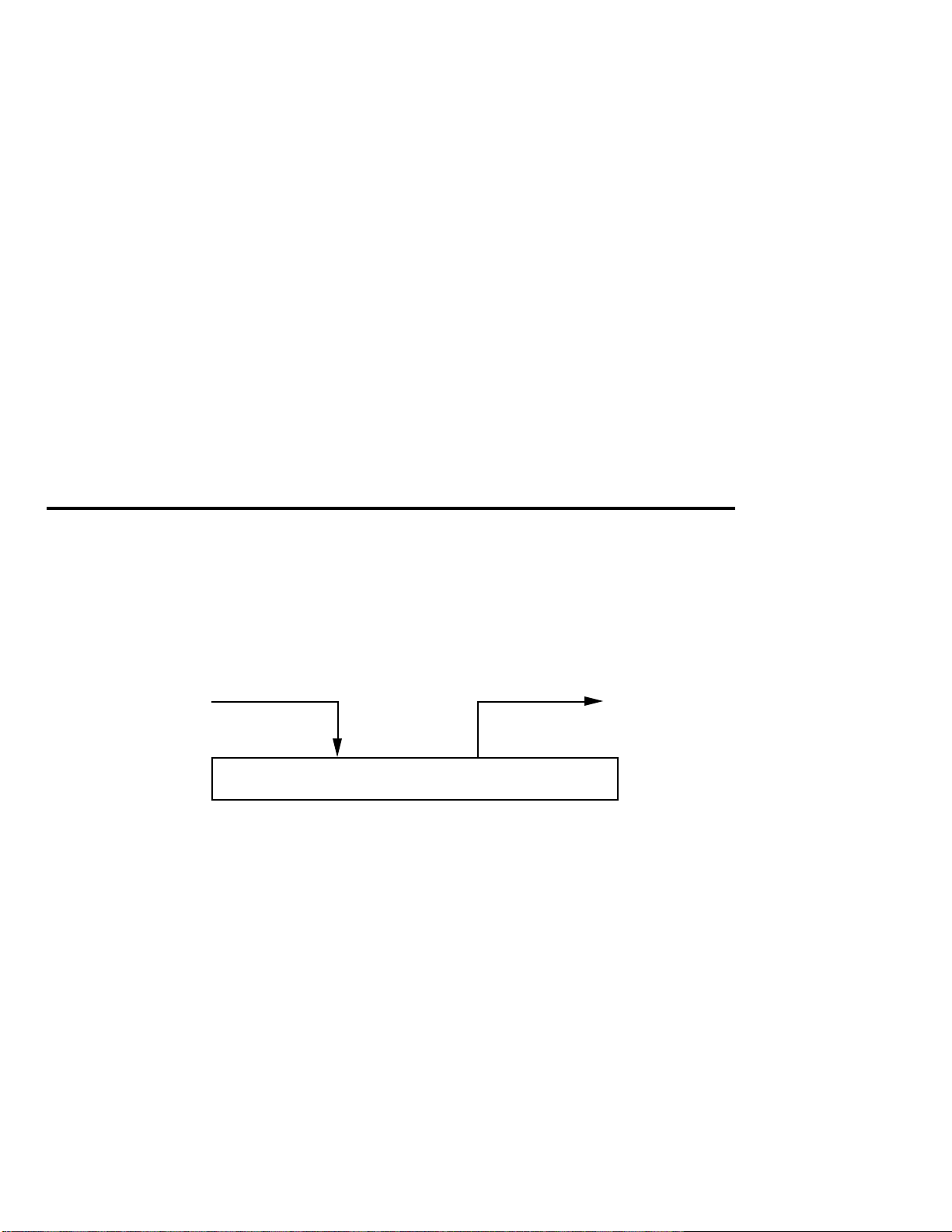
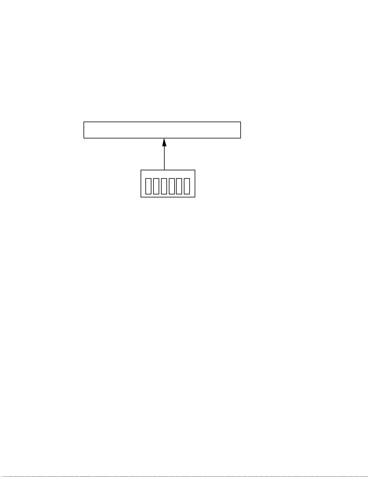
Mono In, Mono Out
From
guitar
Right Input Right Output
Application Mono guitar feeding a mono amp, PA, or mixer.
Hookup Patch the guitar into the right input and feed the right output
to your amplifier (Using the left input and output will also work, but for
the sake of consistency and simplicity, we'll just refer to the right input
and output).
to mono amp,
PA, or mixer
3
Page 12
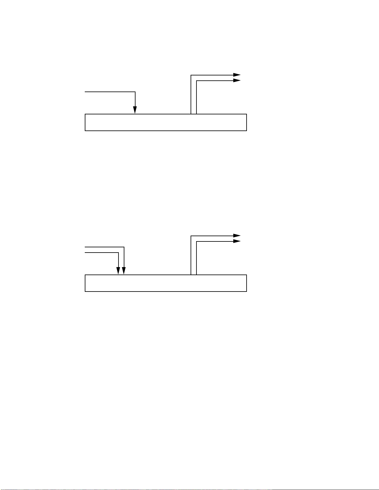
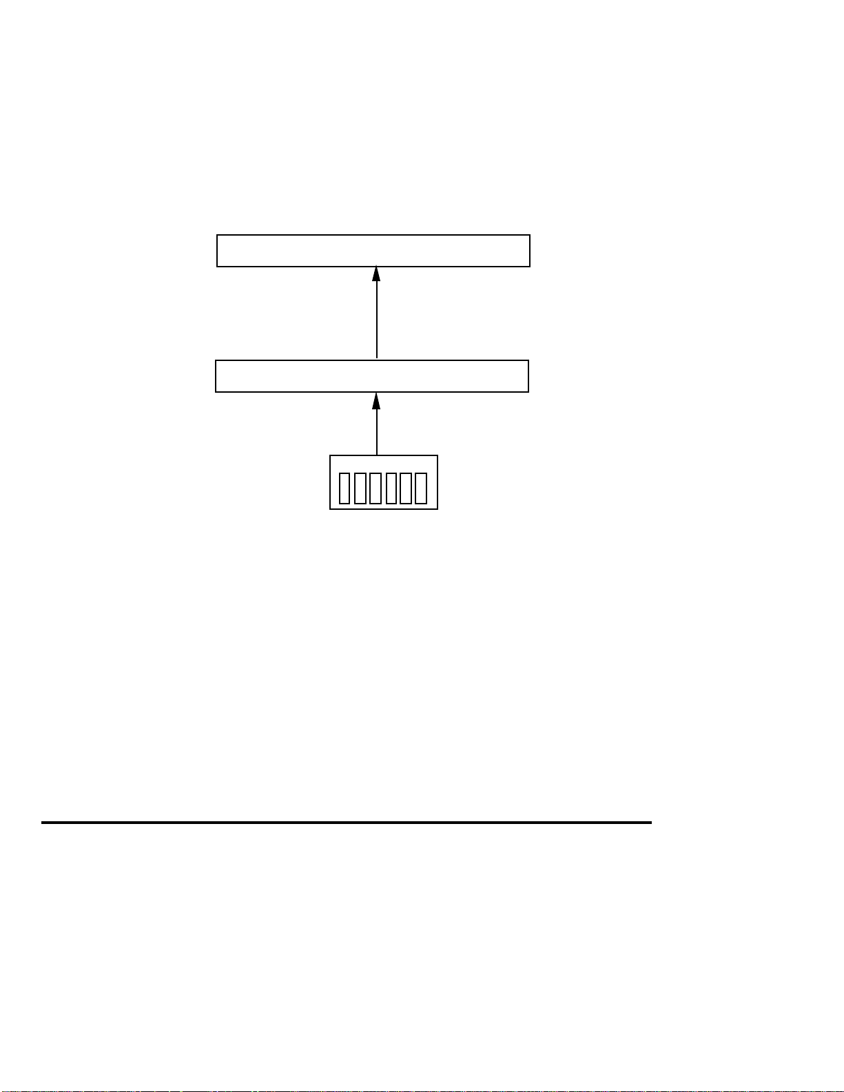
Mono In, Stereo Out
From
guitar
to stereo amp,
PA, or mixer
Application Mono guitar feeding a stereo amp, PA, or mixer.
Hookup Patch the guitar into the right input and feed the right and left
outputs to your amplifier.
Stereo In, Stereo Out
From
guitar
Left
Input
Right
Input
Right
Input
Left
Output
Left
Output
Right
Output
to stereo amp,
PA, or mixer
Right
Output
Application Stereo guitar feeding a stereo amp, PA, or mixer.
Hookup Patch the guitar into the right and left inputs and feed the right
and left outputs to your amplifier.
4
Page 13
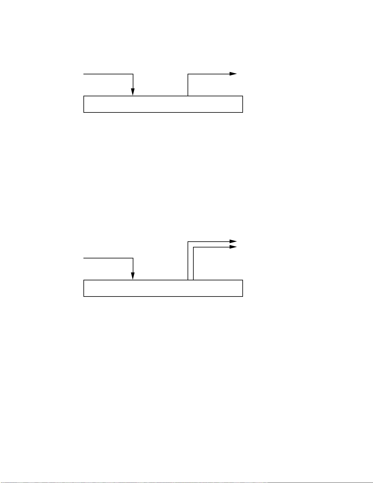
Mono Send, Mono Return Effects Loop
from effects
loop send
Right Input Right Output
Application Patching into a guitar amp with a mono effects loop. Do not
confuse this with the QuadraVerb GTÕs internal effects loop; the loop in
an amplifier is specifically designed for the insertion of signal processors
such as the QuadraVerb GT.
Hookup Patch the effects loop send into the right QuadraVerb GT input
and feed QuadraVerb GT's right output to the effects loop return.
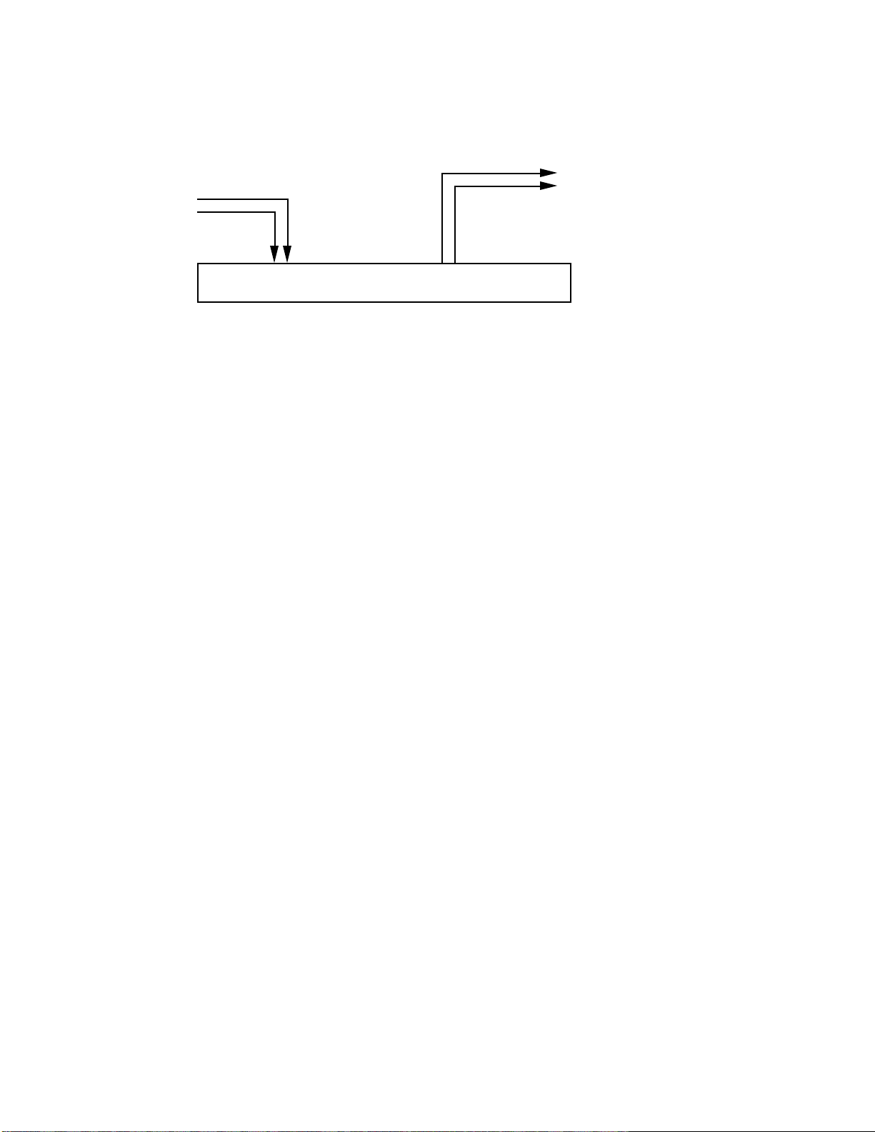
Mono Send, Stereo Return Effects Loop
From effects
loop send
to effects
loop return
to effects loop
stereo returns
Right
Input
Left
Output
Right
Output
Application Patching into a guitar amp with a mono send and stereo
return effects loop. Do not confuse this with the QuadraVerb GTÕs
internal effects loop; the loop in an amplifier is specifically designed for
the insertion of signal processors such as the QuadraVerb GT.
Hookup Patch the effects loop send into the right QuadraVerb GT input
and patch the QuadraVerb GT's right and left outputs to the effects loop
stereo return.
5
Page 14
Stereo Send, Stereo Return Effects Loop
From effects
loop sends
to effects
loop returns
Left
Input
Right
Input
Left
Output
Right
Output
Application Patching into a guitar amp with a stereo send and stereo
return effects loop. Do not confuse this with the QuadraVerb GTÕs
internal effects loop; the loop in an amplifier is specifically designed for
the insertion of signal processors such as the QuadraVerb GT.
Hookup Patch the effects loop sends into the right and left QuadraVerb
GT inputs, and patch the QuadraVerb GT's right and left outputs to the
effects loop stereo return.
6
Page 15

Interfacing with Mixer Stereo Effects Sends
From mixer
sends
Left
Input
Right
Input
Application Patching into a mixer's stereo effects sends for use as a
reverb or other processor while recording.
Hookup Patch the mixer's auxiliary bus (or effects bus) sends into the
right and left QuadraVerb GT inputs, and patch the QuadraVerb GT's
right and left outputs to the mixer's stereo returns or if not available,
two standard mixer channel inputs.
1.4 FOOTSWITCH HOOKUP
There are two footswitch jacks on the rear panel that accept standard,
normally open, momentary contact footswitches.
Left
Output
to mixer
returns
Right
Output
A footswitch plugged into the Bypass jack duplicates the BYPASS button
function. Press on the footswitch to toggle between bypass and active
modes. When bypassed, the LED in the middle of the BYPASS button
will be lit.
A footswitch plugged into the Advance jack increments (or decrements)
7
Page 16

the program number by one with each footswitch press. You can set an
upper and lower program number limit, as described in section 5.7.
1.5 EXTERNAL EFFECTS HOOKUP
The QuadraVerb GT offers an effects loop where you can patch in effects
other than the ones included in the unit (you might want to insert, for
example, a wah-wah pedal or vintage fuzz). The effect can be bypassed or
enabled for each patch.
Patch the Effects Loop Send jack to the effect input, and the Effects Loop
Receive jack to the effect output. Also note that the Send jack provides a
post-analog effects, pre-digital effects send suitable for driving guitar
amps or a studio console; the Receive jack lets you plug directly into the
digital effects and bypass the analog effects. The effects loop can therefore
split the QuadraVerb GT into two separate effects, as described in section
2.1.
It is important to note that turning off the effects loop does not turn off
the effects send. Selecting In or Out on the Effects Loop page will only
enable or disable the Effects Loop Return jack. Also, the effects loop will
be bypassed if there are no jacks inserted, regardless of whether the
Effects Loop page is set to On or Off.
8
Page 17

1.6 SETTING LEVELS
After hooking up your cables, set the proper levels. Start off with your
amplifier turned down to a low volume to prevent any ear-shattering
surprises as you learn about the QuadraVerb GT. After you know what
you're doing, increase the level to normal monitoring levels.
1. Press the BYPASS button (its red LED will light) so that you hear only
the straight guitar sound.
2. Play your instrument and observe the 4-step LED meter toward the
left of the QuadraVerb GT.
3. Adjust the Input control so that the -6 dB LED lights consistently but
the Clip (red) LED lights rarely, if ever. The red LED indicates that
distortion is either about to occur or is actually occurring.
4. Adjust the output control for a comfortable monitoring level. Make
sure the output is turned up high enough to provide the amplifier,
mixer, or subsequent processor with sufficient level, but not turned
up so high that it overloads the unit it is feeding.
5. Press the BYPASS button again so that you can hear the effect of the
different QuadraVerb GT programs. BYPASS can be used at any time
to toggle between processed and straight sounds.
1.7 CHECK OUT THE FACTORY PROGRAMS
The QuadraVerb GT contains 90 programs that put your guitar through
serious sonic gyrations. Initially, these programs contain factory presets.
However, they can be edited or replaced with your own programs. You
can also recall the original factory sound associated with a program
location at any time, even if that location has been modified or erased,
because the parameters for these programs are stored in ROM
(permanent memory).
Assuming you've hooked up your guitar as described in the previous
section, it's time to audition the QuadraVerb GT programs and see what
this baby can do.
9
Page 18

Selecting Programs
1. Press the PROGRAM (PROG) button. The LED in the middle of the
button will light.
2. There are three ways to select programs:
¥ MIDI program changes. See next section.
¥ Press either VALUE button to scroll through the available programs
(VALUE UP increases the program number, VALUE DOWN
decreases the program number). The harder you press the VALUE
button, the faster the Program numbers will scroll. Stop on a
program, and it will be selected.
¥ Key in a particular two-digit program number. Note that the module
buttons (REVERB, DELAY, PITCH, etc.) also have numbers printed in
gray. These can be used for entering numbers as long as the
PROGRAM button is held down.
Example: To enter program 56, press the PROGRAM button and
while it is being held down, press the 5 (MIDI) and 6 (CONFIG)
buttons. The display will show 56, and that program will be selected.
If you release the PROGRAM button before entering the two digit
program number, the program number will revert to what it was
before you pressed the PROGRAM button.
The number you enter must be a two-digit number, so enter a
Òleading zeroÓ if necessary. Example: To enter program 9, enter 09.
1.8 MIDI HOOKUP
MIDI is an internationally-accepted protocol that allows musical-related
data to be conveyed from one device to another. See the MIDI
supplement if you are not familiar with how MIDI works.
The most popular MIDI applications are hooking up a MIDI footswitch
to change programs, and/or a MIDI continuous controller pedal to vary
QuadraVerb GT parameters in real time, as you play. The following
sections describe how this process works.
10
Page 19
MIDI Program Selection
MIDI In
Footswitch
MIDI Out
The QuadraVerb GT responds to MIDI program change commands.
Therefore, sending a particular program number via MIDI to the
QuadraVerb GT will call up the program you specified.
If a device can generate program change commands, patching its MIDI
Out to the QuadraVerb GT's MIDI In allows for remote program
selection.
Several devices can generate program change commands:
¥ MIDI footswitch This is probably the option that most guitarists will
use. A MIDI footswitch sends program changes in response to
footswitch presses. Many companies make MIDI footswitches; their
manuals explain how to program the footswitch to send out
particular program changes.
¥ MIDI sequencer A sequencer can record and play back MIDI data,
including program change commands.
¥ Synthesizer Selecting a new program on a synthesizer usually sends
out a corresponding program change command. This allows any
signal processor hooked up to the synth to change its settings in
response to different synth programs.
¥ Other effects boxes If you use more than one effects box, calling up a
program on it will often send a corresponding program change
through its MIDI Out.
NOTE: Your QuadraVerb GT and the MIDI footswitch must both be set to
the same MIDI channel to execute program changes.
11
Page 20

MIDI Controller Pedal Hookup
MIDI In
Footswitch
Controller Pedal
MIDI In
Footswitch
Controller Pedal
MIDI
Several QuadraVerb GT parameters can be changed remotely over MIDI.
Usually this is done with a footpedal that generates MIDI continuous
controller data. There are 128 controllers, most of which are available for
remote parameter control (some of the higher-numbered controllers are
used to set up synthesizer modes and other things we donÕt need to
worry about).
The basic idea is to set the parameter to be controlled to a particular
controller number. Then set the pedal to the same controller number. As
you vary the pedal, it will generate data that will change the QuadraVerb
GT parameter. For example, assigning a foot pedal to delay feedback
would allow you to kick in a slapback delay at the end of a phrase.
The MIDI controller pedal may be part of your footswitch unit, a separate
stand-alone device, or a combination standard volume pedal and
converter (e.g., Anatek Pocket Pedal). Synthesizers and other devices
also generate MIDI continuous controller data.
If you want to feed the QuadraVerb GT with both a footswitch for
program change control and a pedal for real time control, either the
footswitch or pedal will need a merging input, or you will need a MIDI
merger.
Merger
12
Page 21
MIDI Thru/Out Hookup
MIDI In
Footswitch
MIDI Out
MIDI Thru/Out
MIDI In
The MIDI Thru/Out jack can have its function changed via software (see
section 5.4). When MIDI Thru is turned on, this jack carries a duplicate
of the MIDI data appearing at the MIDI In jack. In addition to the Thru
function, the Thru/Out jack can then feed the MIDI In of other MIDIcontrolled unit, thus distributing the MIDI signal to two different units.
In addition to the Thru function, data generated by the QuadraVerb GT
can be sent to other MIDI units. This is more of a feature for advanced
MIDI users and is described in sections 5.5 and 5.6 on QuadraVerb GT
System Exclusive options (for more information on System Exclusive
information, see the MIDI supplement). Generally, the data generated
from the QuadraVerb GT is used for one of two purposes:
¥ Transfer program data directly from one QuadraVerb GT to another.
¥ Send program data to a such as the Alesis DataDisk or other MIDI
storage device in order to back up the data inside the QuadraVerb GT.
1.9 ROCK OUT!
Play for a while and get a feel for how the QuadraVerb GT sounds. The
factory programs give a good idea of what the QuadraVerb GT can do,
and can also be modified later on if you want to customize the factory
programs to your own specifications.
13
Page 22

CHAPTER 2 Ð QUADRAVERB GT MODULES
AND CONFIGURATIONS
Many guitarists will find that the 90 factory presets take care of most, if
not all, of their musical needs. However, the QuadraVerb GT is a very
flexible device and comes into its own when edited to your own specific
needs.
To do this, it is necessary to understand the QuadraVerb GT's effects and
configurations, which is what this chapter is all about. The next chapter
covers how to edit those effects and configurations.
2.1 ABOUT THE QUADRAVERB GT's EFFECTS
The QuadraVerb GT has 11 main effects sections (including the mixer)
and the ability to alter (modulate) some of the effects parameters in real
time. Each effect modifies your signal in a particular way. A particular
combination of the 11 effects is called a configuration, as explained in
section 2.2.
Preamp
The Preamp section includes effects found in standard rack preamps,
such as compression, overdrive, distortion, flat/bright/presence switch,
bass boost, cabinet simulator, and noise gate.
This section is followed by a programmable effects loop that lets you
insert your favorite classic wah-wah, phase shifter, etc.; you can enable or
bypass the effect as part of a program. This loop can also be used to split
the QuadraVerb GT into two separate effects (see the last part of this
section on ÒBi-TimbralÓ Effects).
Reverb
Reverb is made up of a large number of distinct echoes, called reflections.
In a natural acoustic space, each reflection's amplitude and brightness
decays over time. This decaying action is influenced by the room size, the
location of the sound source in the room, the hardness of the walls, and
other factors.
14
Page 23

Delay
There are five main reverb types, as described later. Furthermore, any
reverb type can be gated, which is the process of abruptly cutting off the
reverbÕs decay for a more ÒchoppyÓ sound.
Delay provides a discrete repetition of a signal. By adding feedback
within the effect, the delayed signal can repeat many times, with each
successive decay softer than its predecessor. The QuadraVerb GT offers
four types of delay:
¥ Ping-Pong Delay In stereo, the delayed signal bounces back and forth
between channels, with the speed determined by the delay time
parameter. Maximum delay is 375 milliseconds in QuadMode, 400ms
in the Lezlie and Ring Modulation configurations, 750 ms in the
Graphic > Delay configuration, 705ms in the 5 Band EQ > Pitch >
Delay configuration, and 320ms in the Resonator configuration.
¥ Stereo Delay This has two individual delays, one for each channel.
Setting them to different delay times allows for polyrhythmic delays.
Maximum delay specs are the same as for ping-pong delay.
¥ Mono Delay Because this is a single delay line, it has twice the
maximum delay time of the stereo delay (up to 1500 ms).
¥ Multitap Delay Available only in the 5 BAND EQ > PITCH > DELAY
configuration, this delay includes 8 taps with variable delay time,
volume, panning, and feedback amount for each tap. The total delay
time of all eight delays cannot exceed 1470 ms.
Pitch Change
This module alters the pitch of a signal in various ways to produce
ÒanimatedÓ timbres that are more complex than the original signal. The
various pitch change options are:
¥ Chorus This combines a delayed (typically 10-25 ms), detuned
version of the original signal with the straight signal. Modulating the
delayed version creates phase, amplitude, and time differences that
sound like two instruments playing together. Mono and stereo
functions are available; stereo modulates two delayed signals instead
15
Page 24

of just one.
¥ Flanging Flanging is similar to chorusing, but modulates the delayed
signal over a much shorter delay range (typically 0-12 ms). This
produces a Òjet airplaneÓ-like sound. Mono and stereo flanging is
available, and the flange modulation sweep can be triggered in order
to sync up with the rhythm of your playing.
¥ Detune Shifts the pitch by a fixed amount. This creates a thickening
effect similar to the difference between a 12-string and 6-string guitar.
¥ Phase Shifter This effect is similar to flanging, but covers a narrower
delay range and has a more diffused timbral quality.
¥ Lezlie Speaker Simulator With the Lezlie configuration selected, the
pitch change module becomes a rotating speaker simulator. Rotating
speakers, which involved mechanically rotating one or two speakers
to produce complex timbral changes, were extremely popular during
the 1960s.
Equalization
Equalization provides control over the tone of your signal by altering the
frequency response in various ways. The QuadraVerb GT's three
different types of EQ are:
¥ 3 Band Parametric This combines high and low frequency shelving
equalizers (like the tone controls found on stereo systems and guitar
amps) along with a sweepable midrange parametric stage (see Ó5 Band
Parametric,Ó next) that has variable boost or cut, frequency, and
bandwidth (resonance, or ÒbiteÓ). This works well for dialing in
rhythm guitar sounds.
The high and low shelving bands offer two parameters, amplitude
and frequency. Amplitude sets the amount of boost or cut; frequency
sets the frequency at which the maximum boost or cut occurs. This
boost continues for frequencies higher than the high frequency and
lower than the low frequency.
16
Page 25

The middle band is parametric and offers amplitude, frequency, and
bandwidth parameters as described next.
¥ 5 Band Parametric This is identical to the 3 Band Parametric but
offers two additional sweepable midrange stages with variable boost
or cut, frequency, and bandwidth. The following diagram shows the
relationship between three parameters.
The complex response of the 5 band parametric lets you compensate
for dead spots on a guitar's neck, or set up a very specific frequency
response.
¥ 11 Band Graphic The graphic equalizer can boost or cut any of 11
different bands (16 Hz, 32 Hz, 62 Hz, 126 Hz, 250 Hz, 500 Hz, 1 kHz, 2
kHz, 4 kHz, 8 kHz, and 16 kHz.
17
Page 26

Panning and Tremolo
Panning shifts the signal back and forth between the stereo outputs at a
cyclical, adjustable rate. Tremolo provides a ÒpulsingÓ sound via cyclical
level changes. Both have ÒdepthÓ parameters; with panning this varies
the width of the pan in the stereo field, with tremolo this sets the
difference between volume peaks and valleys.
Ring Modulation
Ring modulation shifts a signal's harmonics up and/or down by an
adjustable frequency (expressed in Hertz). The QuadraVerb GTÕs ring
modulator features individual outputs for the up and down signals. The
resulting sound takes on a Òclangorous,Ó bell-like quality that is used
mostly with percussive effects. Try this on a drum machine, or muted
guitar parts.
Tunable Resonators
A resonator is a filter whose response is so sharp that it actually imparts
a pitch to any signal going through it. In the Resonator configuration,
there are up to five resonators, depending on the configuration, so you
can tune the resonators to complex chord types. You can also transpose
the resonator frequencies via MIDI notes to match a particular chord
progression.
Sampling
Sampling is the process of digitally recording a signal into the
QuadraVerb GT's memory, which can then be triggered via an external
audio input (e.g., a snare drum sound coming from a tape track), a front
panel button, or a MIDI note. Different MIDI notes will transpose the
sample. Sampling is useful if you want to capture a particular effect or
chord change, then play over it. Try it in the studio for drum sound
replacement, reproducing unusual vocal effects, etc.
Mixer
The multiple effects are all placed in parallel. Each effectÕs output feeds a
18
Page 27

mixer, and is variable so that you can change the balance of that
particular effect with respect to the overall sound.
The effect input can come from the main input if you only want the
effect to process the dry sound, but in many configurations, the effect can
get its input from the output of other effects, or from a combination of
processed and dry sounds.
Modulation
As mentioned earlier, many QuadraVerb GT parameters can be changed
in real time via pedals that generate continuous controller commands,
or from commands issued by a sequencer or synthesizer. Continuous
controller pedals are available from a variety of manufacturers at
various price points. These generate signals that are ÒtaggedÓ with a
particular controller identification number. If you set a QuadraVerb GT
parameter to be controlled by this particular controller number, moving
the pedal will change the QuadraVerb GT parameter.
Modulation consists of choosing up to 8 ÒtargetÓ parameters to be
modulated by any one of several types of MIDI ÒsourceÓ data types (pitch
bend, aftertouch, note number, and note velocity as well as continuous
controllers). Several parameters can be changed by one controller, so
that, for example, moving a pedal could increase chorus depth and boost
the midrange frequencies.
ÒBi-TimbralÓ Effects
The QuadraVerb GT can serve as two separate effects units by proper
patching to and from the effects loop. For example, consider a situation
where a guitarist plays guitar and sings. Plug the guitar into the
QuadraVerb input; the effects loop send provides the post-analog effects
signal, which can be routed to a guitar amp. Meanwhile, the voice mic
can be externally preamplified and sent into the effects loop return. This
allows the vocal to be processed by the digital chorus, reverb,
equalization, etc. sections. The QuadraVerb GT output, which now
carries only the processed vocal sound, can be routed to a PA for further
amplification.
19
Page 28
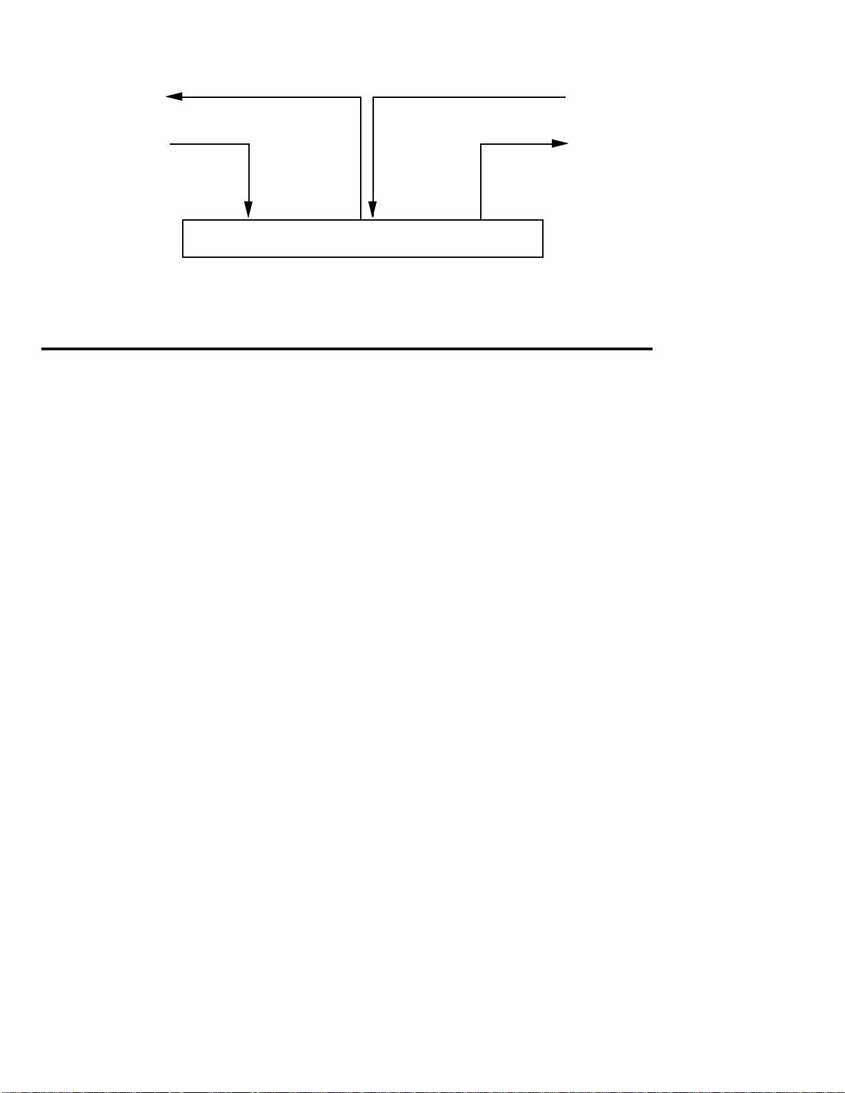
Right Output
to PA
Effects Return
From guitar
Effects Send
from Microphone
to Amplifier
Right Input
2.2 ABOUT CONFIGURATIONS
No matter which program you select, the analog effects are always in the
same order. However, the digital effects can be connected together in one
of eight different ways, each of which is called a configuration. A
configuration doesn't just include a specific collection of effects, but also
the way in which they interconnect (e.g., whether the delay signal is
derived from an equalized or non-equalized signal). This allows for a
great deal more flexibility than you would expect from a fixed
configuration of effects.
This flexibility allows for some great sounds, but also requires a bit of
experimentation to learn the subtleties of each configuration and how
these subtleties affect the sound. It's probably easiest to start off by
ÒtweakingÓ the factory presets to learn what the different parameters do,
then graduate to creating programs from scratch.
These configuration descriptions use block diagrams to indicate signal
flow. Keep the following in mind:
¥ Think of the connecting lines as Òpatch cordsÓ between different
Òeffects boxesÓ (the individual modules).
¥ Switches are enclosed in rectangular boxes with rounded corners.
¥ The knobs act as volume controls if two wires hook into the knob, or
mix (ÒpanÓ) between two signals (incoming wires) and provides an
output (outgoing wire) if three wires hook into the knob.
¥ Heavy lines indicate a stereo path. Note that most effects output a
stereo signal, but accept a summed, mono signal at the input.
20
Page 29
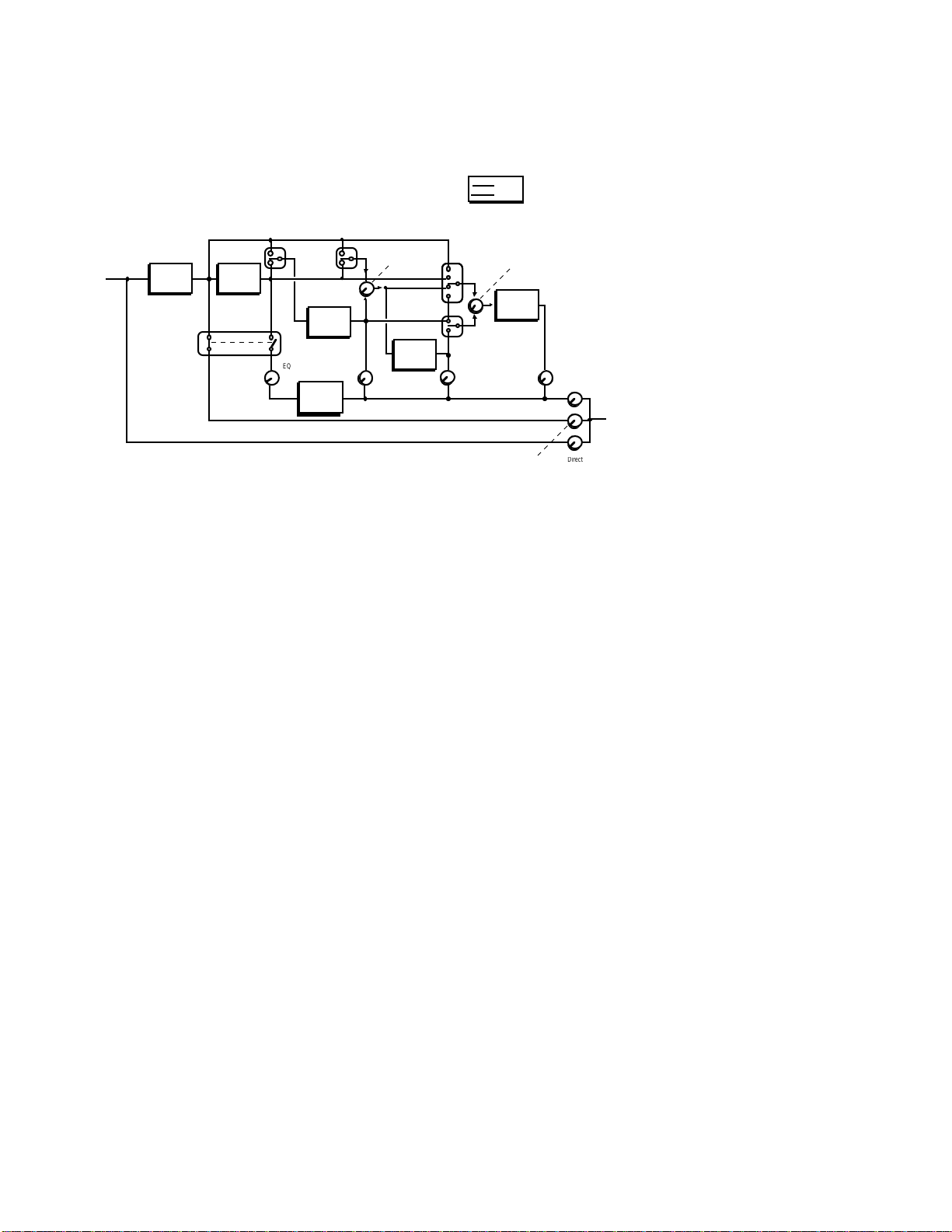
#1 Preamp > EQ > Tremolo/Panning > Pitch > Delay > Reverb
EQ
PITCH
DELAY
PANNING
TREMOLO
REVERB
Pitch
Delay
Delay
Reverb
x
EQ
Pitch
Delay
Reverb
Reverb
Reverb
Effects
INPUT
OUTPUT
Configuration 1
Mono
Stereo
Direct Output
Pre-Amp Signal
PREAMP
Preamp
Pre/Post EQ
Input
Output
Input 1
&
Input Mix
Output
Output
Input 1
Input 2
Input Mi
Output
Output
QuadModeª is a complex configuration that offers comprehensive
switching and mixing possibilities. ItÕs excellent for creating larger-thanlife, animated sounds.
The Pitch module can switch its input between the preamp or EQ signals.
The Delay moduleÕs Delay Input Mix control chooses a blend between
the output of the Pitch module, or the preamp or EQ signal (as selected
by the Delay Input 1 switch).
The Reverb moduleÕs Reverb Input Mix control chooses a blend between
two input options. Reverb Input 1 switches between preamp, EQ, preDelay, or post-Pitch signals; Reverb Input 2 switches between the postDelay or post-Pitch signal.
Panning and Tremolo are available in this configuration, and are in
series with the preamp or EQ signal line. The Preamp Signal Pre/Post EQ
switch chooses whether the Preamp Output comes from preamp or EQ.
21
Page 30
#2 Preamp > Lezlie > Delay > Reverb
LEZLIE
DELAY
REVERB
Delay
Lezlie
Reverb
Reverb
Effects
Delay
Reverb
Reverb
INPUT
Direct Output
PREAMP
OUTPUT
Configuration 2
Mono
Stereo
Output
Input 1
Input 2
Input Mix
Output
Output
Input Mix
Output
This is similar to the QuadModeª configuration, but replaces the EQ
and Pitch modules with a Lezlie (rotating speaker simulator) module
and does not have a Preamp level control.
The Lezlie module simulates the common two-speaker system with two
different speeds. The switching and mixing options are similar to those
used in QuadMode. This configuration produces complex frequency and
amplitude modulation effects and works very well with rhythm guitar.
22
Page 31

#3 Preamp > Graphic EQ > Delay
GRAPHIC
DELAY
Delay
EQ
Delay
Effects
INPUT
Direct Output
PREAMP
OUTPUT
Configuration 3
Mono
Stereo
5 BAND
PITCH
PANNING
O
Pitch
Delay
EQ
INPUT
OUTPUT
Pre-Amp Signal
PREAMP
Preamp
DELAY
Direct Output
Effects
Delay
Pitch
Delay
Configuration 4
Mono
Stereo
Input
EQ
Output
Output
This combines the 11 band graphic EQ with delay. The EQ provides
sophisticated sound-shaping for the preamp sound, and the delay adds
ambience for lead effects.
#4 Preamp > 5 Band EQ > Tremolo/Panning >
Pitch Change > Delay
Output
Output
Input Mix
Output
Output
EQ
Pre/Post EQ
Input
Output
Input 1
&
TREMOL
This is just the ticket for rich chorus sounds. Use the 5 Band EQ to shape
your timbre, Pitch Change to add chorusing (or other pitch effects such as
flanging, etc.), and Delay to add evocative echo effects. Using the Multi
Tap option in the Delay module creates unusual echo effects along with
chorusing.
The Pitch module can switch its input between preamp or EQ signals.
The Delay moduleÕs Delay Input Mix control chooses a blend between
the output of the Pitch module, or the preamp or EQ signal (as selected
by the Delay Input 1 switch).
23
Page 32

Multi Tap delay is also available in this mode along with the standard
INPUT
PREAMP
OUTPUT
Pre-Amp Signal
Direct Output
Effects
O
Delay
EQ
Preamp
Reverb
REVERB +
CHORUS
3 BAND
EQ
Configuration 5
Mono
Stereo
mono, stereo, and ping-pong delays. Up to eight taps are available along
the delay line; each tap has variable delay time, panning, volume, and
feedback. For more details about multitap delays, see section 4.5.
Panning and Tremolo are available in this configuration, and are in
series with the EQ signal line. The Preamp Signal Pre/Post EQ switch
chooses whether the Preamp Output comes from before or after the EQ.
#5 Preamp > 3 Band EQ > Reverb
Input
Output
Pre/Post EQ
Output
utput
This is the recommended configuration when you want the best possible
reverb sound. By restricting the number of effects, the QuadraVerb GT
can devote its full computing power to creating awesome reverberation
effects. However, EQ is still available for additional tone shaping, as is a
simpler version of chorusing.
24
Page 33

#6 Preamp > Ring Modulator > Delay > Reverb
RING
MOD
INPUT
PREAMP
OUTPUT
Pre-Amp Signal
Direct Output
DELAY
REVERB
Effects
Delay
Reverb
Reverb
Reverb
Reverb
Delay
Ouput
Delay &
Ring
Up
Down
Configuration 6
Mono
Stereo
DELAY
Reverb
Reverb
Reverb
REVERB
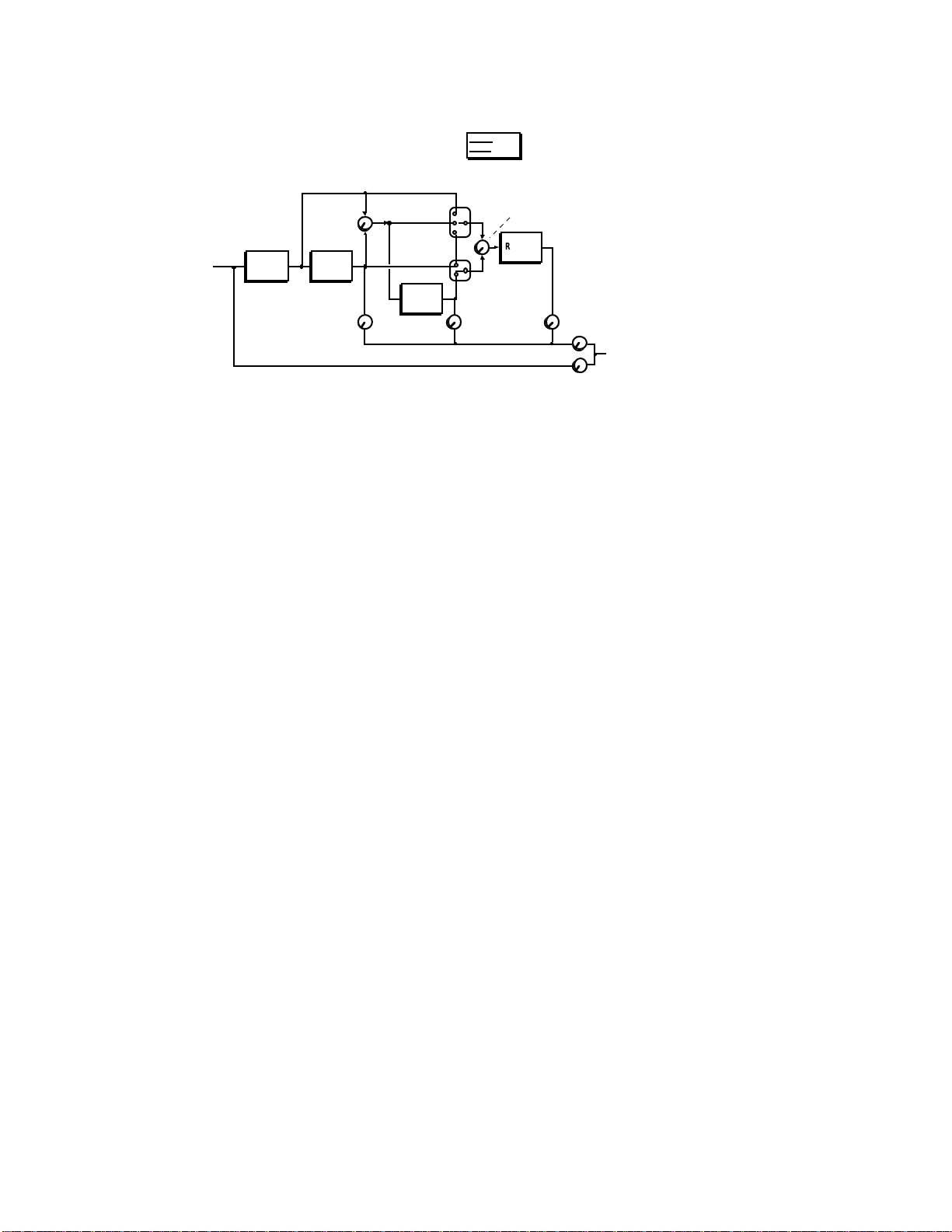
RESON 1
RESON 2
RESON 3
RESON 4
RESON 5
INPUT
PREAMP
OUTPUT
Pre-Amp Signal
Direct Output
Effects
Delay
Reverb
Delay
Resonator
Configuration 7
Mono
Stereo
Modulator
Output
Input Mix
Shift
Mix
Reverb
Shift Mix
Input 1
Output
Input Mix
Input 2
Output
Output
This configuration features the Ring Modulation in conjunction with
Delay and Reverb. The Ring Modulator is not available in other
configurations.
The Ring Modulator produces two outputs, both of which are
mathematically derived (sum and difference frequencies) from the input
signal. The Ring Modulator output can pan between these two output
signals, as can the Delay & Reverb Shift Mix control, which chooses a
blend of both outputs to send to the Delay and Reverb inputs.
#7 Preamp > Resonators > Delay > Reverb
Input Mix
Output
This configuration features the Resonators in conjunction with Delay
and Reverb.
25
Input 1
Output
Input Mix
Input 2
Output
Output
Page 34

#8 Preamp > Sampling
SAMPLING
INPUT
PREAMP
OUTPUT
Pre-Amp Signal
Direct Output
Sampling
Trigger In
Pitch In
Trigger
Audio
MIDI
Looping
Start
Length
Configuration 8
Mono
Stereo
In this configuration, you can record sounds (processed by the Preamp if
desired) into the QuadraVerb GT and play them back in a variety of ways.
Trigger
Note
On-Off
Output
26
Page 35

CHAPTER 3 - BASIC EDITING
TECHNIQUES
Editing is the key to using the QuadraVerb GT to its fullest potential. If
you like a sound but want more reverb, less treble, more distortion, or
whatever, editing is the answer.
Make sure that if you develop a custom set of programs, that you save
your data to some form of MIDI system exclusive storage device, like the
Alesis DataDisk (see sections 5.5-5.6).
3.1 HOW EDITING WORKS
The QuadraVerb GT contains five Effects Groups, each with its own
corresponding front panel selection button: Reverb, Delay, Pitch,
Equalization (EQ), and Guitar Preamp (Pre-Amp). These all contain
editable parameters. Four other editable functions (with front panel
buttons) are also available: MIDI, Name/Mod, Mix, and Configuration.
The basic editing procedure is the same for whatever you want to edit;
weÕll get into specifics later.
1. Select What You Want to Edit
Push the button associated with the Effect Group (Reverb, Delay, Pitch,
EQ, Preamp) or function (MIDI, Config, Mix, Mod) you want to edit. The
LED in the middle of the button will light.
2. Select the Page with the Parameter to be Edited
Each effect/function includes several pages. Each page shows the name
and value of one (or sometimes more) parameters, and each parameter
controls some particular aspect of the QuadraVerb GTÕs sound or
operation. Most effects or functions require multiple pages to show all
available parameters.
The page's upper display line shows the parameter name, and the lower
line, the parameter value. Press the PAGE UP and DOWN buttons to
select a page containing a parameter to be edited. The harder you press
the PAGE button, the faster the pages will scroll.
NOTE: The NAME/MOD button is the exception to this rule,as it
27
Page 36

accesses both program name parameters as well as the QuadraVerb GT's
MIDI modulation parameters. (See section 3.4)
3. Change the Parameter's Value
A parameter's value is like the Òcalibration scaleÓ a knob would point to
on a regular guitar effects box, except instead of setting a physical device
to a certain position, you see the parameter setting on the screen and
adjust its value with a pair of buttons (increase/decrease value). For
example, a volume knob on a guitar amplifier might be set to 5 would be
the same as a volume parameter with a range of 00-99 set to 50. In either
case, the control is set halfway.
A small line under a parameter indicates it can be edited. Use the
VALUE buttons to change a parameter's value. The harder you press the
VALUE button, the faster the values will scroll.
4. Edit More Parameters
Repeat steps 1-3 until all the parameters you want to edit have been
edited.
Notes
¥ All edits are not made to the original program, but to a copy of the
program that resides in a special place in QuadraVerb GT memory
called the Edit Buffer. A decimal point to the right of the program
number indicates that you are listening to an edited program in the
Edit Buffer. You must save an edited program by transferring the edit
buffer contents into the original program memory location before
selecting another program, or your edits will be lost.
¥ Each parameter has a default value that works well in most
applications. To return to this value, press both VALUE buttons
simultaneously. See chart on page 113.
28
Page 37

3.2 COMPARING EDITED AND NON-EDITED
VERSIONS OF PROGRAMS
Editing a program does not change the original version permanently
until it is stored (see section 3.3 below). Because your edited version is
separate from the original, you can compare the two versions without
altering the original. This can be very useful if you ÒovereditÓ a program
and want to see if the edited version really does represent an
improvement over the original program. To compare:
1. Press the PROG button.
2. Press the PAGE UP button. The display says * COMPARING * and
you can hear the program you started with.
3. To exit compare mode, hit any button except a VALUE button. IF
YOU PRESS A VALUE BUTTON, YOUR EDITED VERSION WILL BE
LOST.
3.3 SAVING (STORING) EDITED PROGRAMS
1. To save an edited program, press the STORE button. The LED in the
middle of the button will light. The display says:
STORE PROGRAM AT
LOCATION: X X
Éwhere XX is the original program number.
2. To save to a different program number, press the appropriate VALUE
button to select the desired program location.
Warning! This edited program will overwrite the program stored in
this location. Before saving, make sure the program to be overwritten
is expendable.
3. Press the STORE button a second time to save the
program. The display will say PROGRAM STORED.
29
Page 38

3.4 RENAMING PROGRAMS
You may want to give your edited program a distinctive name.
1. Press the NAME/MOD button. The LED in the middle of the button
will light and the display says:
EDIT NAME:
Ò(Name of Song)Ó
2. Use the PAGE buttons to select the character to be changed. Characters
available (in addition to a blank space, Yen symbol, and left and right
arrows) are:
!Ò#$%&Õ
()*+,-.
/012345
6789: ; <
=>? @ABC
DE F GHI J
KLMNOP Q
RS TUVWX
YZ[]^_`
abcdef g
hi j kl mn
opqr st u
vwxyz{ |
}
3. Use the VALUE buttons to select the desired character. To enter a
space, press both VALUE buttons simultaneously (or press the
DOWN VALUE button and scroll to the last character of the character
list, which is a blank space).
4. Repeat steps 2 and 3 until the program is named.
6. To store the name, press the STORE button twice.
7. Press any button other than PAGE or VALUE to exit the Name page.
3.5 RECALLING INDIVIDUAL FACTORY PROGRAMS
1. Press STORE. The LED in the middle of the button will light.
2. Press the PAGE UP button to select the Recall page. The display says:
30
Page 39

RECALL ALESIS
PROG Y Y INTO XX
3. Press either VALUE button to select the program to be recalled (the
first parameter).
4. Press the PAGE UP button again to move the cursor under the second
parameter.
5. The factory program will be recalled into the program selected as the
second parameter. Press either VALUE button to select this program
number.
6. Press STORE to complete the recalling operation.
3.6 RECALLING ALL FACTORY PROGRAMS
1. Press STORE. The LED in the middle of the button will light.
2. Press the PAGE UP button three times. The display says:
RECALL ALL 90
ALESIS PROGRAMS
3. Press STORE and all the program locations will be occupied by factory
programs. Any other data will be overwritten.
31
Page 40

CHAPTER 4 Ð EDITING
CONFIGURATION PARAMETERS
In this section, weÕll describe how to select a configuration, then how to
edit the parameters for each configuration. Please refer to the
configuration block diagrams in section 2.2 for details on how particular
mixing and switching parameters work with a particular configuration.
Remember that after selecting a configuration, the PAGE buttons select
the various pages with different parameters. If a page has more than one
parameter, the PAGE buttons also move between those parameters.
Once a parameter is selected, as indicated by a cursor (small underline),
use the VALUE buttons to change the parameter value.
Sampling is such a different type of application that it has its own
chapter. All sampling parameters are covered in that chapter.
Important! In many of the following sections, a diagram will show what
you can expect to see when you call up a particular page. The parameter
value shown for each page will usually be representative, but when you
actually call up the page on the QuadraVerb GT, a different parameter
value from the one shown in the manual may appear.
4.1 SELECTING A CONFIGURATION
1. Select the program whose configuration you want to change or edit.
2. Press the CONFIG button. The LED in the middle of the button will
light.
3. Use the VALUE buttons to select the desired configuration.
32
Page 41

4.2 SELECTING A CONFIGURATION MODULE FOR
EDITING
After selecting the desired configuration, press the button associated with
the module you want to edit (REVERB, DELAY, PITCH, EQ, or MIX). If
the module is not used in a particular configuration, the display briefly
says:
NOT USED IN THIS
CONFIGURATION
4.3 EDITING PREAMP PARAMETERS
Since all configurations use the Preamp section, weÕll describe those edits
first.
Press the PRE-AMP button. Its LED will light and the first page will show
the compression amount. Use the PAGE buttons to access the various
pages described below.
Compression
A compressor reduces the guitar's dynamic range to increase sustain and
even out amplitude peaks. Recordings often use compression to give a
smooth guitar sound. Compression is an important first link in any
guitar effects chain.
There are seven compression amounts (1-7) with higher numbers giving
more compression. Compression can also be turned off.
Overdrive
The Overdrive stage provides a Òrhythm guitar crunchÓ type of sound as
opposed to the smoother, more biting Distortion module (which is used
more for leads). The overdrive stage also gives a fuller, more
harmonically dense sound than the Distortion module. The QuadraVerb
GT's Overdrive stage utilizes both odd and even order harmonics to
COMPRESSION:
0 7
33
Page 42

attain a warmer, fuller, more tube-like sound.
There are seven overdrive amounts (1-7) with higher numbers giving
more distortion. Overdrive can also be turned off.
Experiment with various settings of both overdrive and distortion to
produce a variety of different tones. It is important to note that you can
get quite a different tone from combining Overdrive and Distortion in
addition to using either of the effects independently.
Distortion
The QuadraVerb GT includes several distortion options, as selected with
the VALUE buttons.
OVERDRIVE:
0 7
DISTORTION:
O FF
Off No distortion
1 Mild distortion for rhythm guitar & smooth leads.
2 A little more bite for leads.
3 Mild rock distortion for rhythm guitar and crunchy leads.
4 Rock distortion for lead or rhythm.
5 Bright, highly overdriven sound for lead and heavy rhythms.
6 Mild heavy metal distortion for rhythm guitar and metal leads.
7 Heavy metal distortion for lead or rhythm with tons of edge.
8 Big shred sound for lead.
Preamp Tone
The display says:
There are three options: Flat (doesn't affect the sound), Presence
(provides a treble boost), and Bright (provides an treble boost/midrange
PREAMP TONE:
F LAT
34
Page 43

cut). Both the Preamp Tone and Bass Boost parameters can be used to
shape the initial sound of your tone, while the EQ and/or Resonators
(see section 4.8) can be used for fine tuning.
Bass Boost
The display says:
Set to On for a fuller, bassier sound. Otherwise, set to Off. The Bass Boost
can also be used to get a fuller sound at low volumes.
Cabinet Simulator
The display says:
BASS BOOST:
O N
CAB SIMULATOR:
O N
Much of the sound of an electric guitar doesn't come from effects or the
power amp, but from the sound of the speaker cabinet. When feeding a
recording console or PA, choose either Cabinet 1 (sounds like two 10Ó
speakers) or Cabinet 2 (simulates a cabinet with four 12Ó speakers). When
using the QuadraVerb GT with a standard guitar amp, leave this set to
Off. However, if you like the sound of the cabinet simulators while using
a guitar amp, it's perfectly OK to use these settings. You be the judge.
Effect Loop
The display says:
The QuadraVerb GT's Effect Loop is designed to let you insert other
signal processing devices into your signal chain. The effect send and
return jacks also allow you to use the analog and digital sections
independently as described in section 2.1.
EFFECT LOOP:
I N
35
Page 44

Noise Gate
The display says:
Extreme compression and distortion settings, as well as hum and noise
picked up from your guitar pickups, can add undesirable noise. The
noise gate cuts off the signal when it dips below a certain threshold level,
as set by the noise gate parameter value. Set the threshold just above the
noise so that your playing exceeds the threshold and passes through the
gate, but residual noise that is present when you are not playing will not
exceed the threshold and will be blocked.
You can set the Quadraverb GT's noise gate threshold manually, or you
can enable the Auto Gate feature to set it for you. The auto gate estimates
a moderate gate level for you, depending on the amount of compression
and distortion you have chosen.
NOISE GATE:
A UTO
To set the noise gate manually, don't play your guitar. If you hear noise,
start with the value at Off and slowly increase value (up to 16) until the
noise goes away. With extremely noisy signals, you may have to
compromise a bit and have either a little bit of noise get through, or
have more of a noteÕs decay get cut off.
Preamp Out Level
The display says:
The Preamp Out Level is located in the Quadraverb GT's digital section,
post-effects return. It controls the level of all of the analog effects as they
are fed into the processor that generates all of the QuadraVerb GT's
digital effects. Proper adjustment of the Preamp Out Level allows you to
prevent overloading of this processor without sacrificing the input level
necessary to provide sufficient gain to drive the QuadraVerb GT's analog
section properly.
PREAMP OUT LEVEL
0 0
To set the Preamp Out Level, do the following:
36
Page 45

1. Press the BYPASS button and play your guitar. Even though you won't
hear any effects, check the QuadraVerb GT's input level meter. If the red
clip light still lights, turn down the Input knob.
2. If the clip LED doesn't light with the BYPASS button pressed, press it
again to disengage the bypass function. Play your guitar and decrease the
Preamp Out Level until the level indicator stops clipping.
4.4 EDITING REVERB PARAMETERS
Reverb Type (configs 1, 2, 5, 6, 7)
In configuration 5, the following reverb type parameters are followed by
the number 2 instead of 1 to remind you that this configuration uses the
ultra-high-performance reverb algorithm.
¥ Plate 1 Provides a bright reverb sound that's popular with vocals and
snares.
¥ Room 1 You can program the room's size and surface (harder or
softer).
¥ Chamber 1 Simulates the acoustic Òecho chambersÓ that were built
into studios prior to the days of high-quality electronic reverb.
¥ Hall 1 This provides a concert hall ambience with long, dense
reflections.
¥ Reverse 1 This type of reverb does not exist in nature; reflections get
louder over time, until they are cut off upon reaching a maximum
volume level.
Reverb Input 1 (configs 1, 2, 6, 7)
The number in [brackets] indicates the configuration in which the
parameter is found. Multiple numbers indicate that the parameter is
found in more than one configuration.
¥ Preamp Output [1, 2, 6, 7] The reverb input signal comes from the
preamp output.
¥ EQ Output [1] The reverb input signal comes after the EQ module.
¥ Lezlie Output [2] The reverb input signal comes after the Lezlie
37
Page 46

module.
¥ Ring Output [6] The reverb signal comes from the Resonator Output.
¥ Resonator Output [7] The reverb signal comes from the Resonator
Output.
¥ Pitch Output [1] The reverb signal comes from the pitch module
output.
¥ Delay Mix Input [1, 2, 6, 7] The reverb signal comes from the Delay
input, which consists of a blend, selected by the Delay Input Mix
parameter, of the pitch output and either pre- or post-EQ signal (as
selected by the Delay Input 1 switch).
Reverb Input (config 5)
¥ Preamp Output [5] The reverb input signal comes from the preamp
output.
¥ EQ Output [5] The reverb input signal comes after the EQ module.
Reverb Input 2 (configs 1, 2, 6, 7)
¥ Delay Output [1, 2, 6, 7] The reverb input signal comes from the delay
output.
¥ Pitch Output [1] The reverb input signal comes from the pitch
module output.
¥ Lezlie Output [2] The reverb input signal is post-Lezlie.
¥ Ring Output [6] The reverb input signal comes from the ring
modulator output.
¥ Resonator Output [7] The reverb input signal comes from the
resonator output.
Reverb Input Mix (configs 1, 2, 6, 7)
The display shows:
REVERB INPUT MIX
1 ¬ 0 0® 2
When set to 00, the signal sources selected in Reverb Input 1 and Reverb
Input 2 are mixed equally into the reverb.
38
Page 47

Larger numbers with the arrow pointing toward 1 indicate that more of
the signal from Reverb Input 1 will be selected. When set to ¬99, only
the signal from Reverb Input 1 will feed the reverb.
Larger numbers with the arrow pointing toward 2 indicates that more of
the signal from Reverb Input 2 will be selected. When set to 99®, only
the signal from Reverb Input 2 will feed the reverb.
Reverb Predelay (configs 1, 2, 5, 6, 7)
The display shows:
REVERB PREDELAY:
0 01 milliseconds
With reverberation, it takes a few milliseconds before the signals from a
sound source go through the acoustic space and encounter a surface, thus
creating the first series of reflections. Predelay is the amount of delay that
occurs before the first reflections begin. This parameter is variable from 1
to 140 ms. The larger this number, the greater the perceived size of the
acoustic space.
NOTE: Don't confuse the Reverb Predelay parameter with the
parameters found in the delay section. The Reverb Predelay is a function
of the Reverb section.
Reverb Predelay Mix (configs 1, 2, 5, 6, 7)
The display shows:
PREDELAY MIX:
PRE ¬ 9 9® POST
This parameter lets you mix some of the non-predelayed signal into the
reverb input. This is useful if you want to hear a bit of reverb
immediately, with more reverb coming in after the amount of time set
39
Page 48

by the predelay parameter.
When set to 00, the predelayed and non-predelayed signals are mixed
equally into the reverb.
Larger numbers with the arrow pointing toward POST indicate that
more of the predelayed signal will be selected. When set to 99® only the
predelayed signal will feed the reverb.
Larger numbers with the arrow pointing toward PRE select more of the
non-predelayed signal. When set to ¬ 99 only the non-predelayed signal
will feed the reverb.
Reverb Decay (configs 1, 2, 5, 6, 7)
The display shows:
REVERB DECAY:
4 0
This determines how long it takes for the reverb to fade out, on a scale of
00 (shorter) to 99 (longer).
Reverb Diffusion Amount (configs 1, 2, 5, 6, 7)
The display shows:
REVERB DIFFUSION
AMOUNT: 1
Diffusion determines the ÒthicknessÓ of the reverb sound by altering the
time that occurs between reverberant reflections. With lower diffusion
settings, you may be able to actually hear the individual echoes that
make up the overall reverb sound. With higher diffusion settings, the
echoes increase in number and blend together. Greater diffusion works
better with percussive sounds, whereas less amounts of diffusion work
well with vocals and other sustained sounds. This parameter is variable
from 1 to 9.
40
Page 49

Reverb Density (configs 1, 2, 5, 6, 7)
The display shows:
REVERB DENSITY:
Usually, in natural acoustic spaces, some time elapses between the first
reflection and all other reflections that make up the reverb sound. If you
listen to only the reverb with Density set to 1, you will hear the source
sound repeat (the first reflection), a short bit of silence, then the onset of
the rest of the reverb. Increasing the Density shortens the time between
the first reflection and the remaining reverb reflections. At the
maximum setting of 9, the reverb will seem to ÒexplodeÓ since the first
reflection will no longer be perceived as a separate echo.
This parameter is very useful with percussive sounds, since an isolated
first reflection may sound like an additional percussive Òhit.Ó It is
available in all of the reverbs except for Hall 1 and Hall 2.
4
Reverb Low Frequency Decay (configs 1, 2, 5, 6, 7)
The display shows:
LOW FREQUENCY
DECAY: - 4 0
Separating the decay times for the high and low frequencies changes the
timbral quality of the reverb over time. The value is always a negative
number since this parameter shortens the time of reverb with low
frequency content compared to the master reverb decay time parameter.
41
Page 50

Reverb High Frequency Decay (configs 1, 2, 5, 6, 7)
The display shows:
HIGH FREQUENCY
DECAY: - 4 0
Separating the decay times for the high and low frequencies changes the
timbral quality of the reverb over time. The value is always a negative
number since this parameter shortens the time of reverb with high
frequency content compared to the master reverb decay time parameter.
Reverb Gate Status (configs 1, 2, 5, 6, 7)
The display shows:
REVERB GATE:
O N
The level of natural, acoustic reverb decays gradually to zero. Gated
reverb abruptly shuts off the reverb ÒtailÓ after a user-settable elapsed
time. The next few parameters control the time the gate stays Òopen,Ó the
amount of time it takes to Òclose,Ó and the residual reverb level that
remains after the gate has closed.
NOTE: Don't confuse the Reverb Gate Status parameter with the Noise
Gate parameter found in the preamp section. The Reverb Gate is a
function of the Reverb section.
Reverb Gate Hold Time (configs 1, 2, 5, 6, 7)
The display shows:
REVERB GATE HOLD
TIME: 0 0
This parameter sets the amount of elapsed time (00-99) before the gate
closes and cuts off the reverb tail.
42
Page 51

Reverb Gate Release Time (configs 1, 2, 5, 6, 7)
The display shows:
REVERB GATE
RELEASE TIME: 0 0
This parameter determines the period of time (00-99) over which the
gate closes. 00 gives an extremely sharp cutoff; 99 gives a more gradual
decay.
Reverb Gated Level (configs 1, 2, 5, 6, 7)
The display shows:
REVERB GATED
LEVEL: 0 0%
The gate does not have to close to a zero level. This parameter sets the
final gate level, from 00 (complete gating action; no residual reverb
sound) to 99 (no gating action; reverb sound only).
4.5 EDITING DELAY PARAMETERS
Delay Type (configs 1, 2, 3, 4, 6, 7)
There are four different types of delay.
¥ Mono Delay This sends the same delay signal to both output
channels. The maximum delay depends on the chosen configuration:
Configurations 1, 2, 6 775, 800, 800 ms respectively
Configurations 3, 4 1500, 1470 ms respectively
Configuration 7 720 ms
43
Page 52

¥ Stereo Delay Each audio channel has its own individual delay
settings. The maximum delay depends on the chosen configuration:
Configurations 1, 2, 6 375, 400, 400 ms respectively
Configurations 3, 4 750, 705 ms respectively
Configuration 7 320 ms
¥ Ping-Pong Delay This delay bounces the delayed signal from left to
right audio outputs, with the speed determined by the delay time.
The maximum delay depends on the chosen configuration:
Configurations 1, 2, 6 375, 400, 400 ms respectively
Configurations 3, 4 750, 705 ms respectively
Configuration 7 320 ms
¥ Multi Tap Delay Available only in configuration 4, this offers up to 8
different taps along a delay line, with variable panning, volume,
delay time, and feedback. The total delay of all taps cannot exceed 1470
ms.
You might want to think of each individual tap as a mono delay line
(being fed from a common source) with its own delay time feedback
and volume parameters that can be panned anywhere in the stereo
field.
Delay Input 1 (configs 1, 4, 6, 7)
¥ Preamp Output The delay input signal comes from the preamp
output.
¥ EQ Output The delay input signal comes after the EQ module.
Delay Input (config 3)
¥ Preamp Output The delay input signal comes from the preamp
output.
¥ EQ Output The delay input signal comes after the EQ module.
44
Page 53

Delay Input Mix (configs 1, 2, 4, 6, 7)
The display shows:
DELAY INPUT MIX:
1 ¬ 0 0® (MODULE)
The lower line shows the blend between the signal selected by Delay
Input 1 and one of several module outputs, depending on the
configuration:
Configurations 1, 4 Pitch
Configuration 2 Lezlie
Configuration 6 Ring Modulator
Configuration 7 Resonator
When set to 00, the signal sources selected in Delay Input 1 and the
module output are mixed equally into the delay.
Larger numbers with the arrow pointing toward 1 indicate that more of
the signal from Delay Input 1 will be selected. When set to ¬99, only the
signal from Delay Input 1 will feed the delay.
Larger numbers with the arrow pointing toward the module name
indicate that more of the signal from the module output will be selected.
When set to 99®, only the module output will feed the delay.
Delay Time (configs 1, 2, 3, 4, 6, 7)
With Mono or Ping Pong selected as the delay type, the display shows:
DELAY TIME:
3 00 milliseconds
With Stereo selected, this will say LEFT DELAY TIME. This sets the time
between successive delay signals, and is variable in 1 ms increments
from 1 millisecond to the maximum delay available in the
configuration.
As mentioned under Delay Type, the maximum delay depends on the
selected reverb type and the configuration.
45
Page 54

Delay Feedback (configs 1, 2, 3, 4, 6, 7)
With Mono or Ping Pong selected for delay type, the display shows:
DELAY FEEDBACK:
3 3%
With Stereo selected, this will say DELAY FEEDBACK LEFT. Increasing
the feedback increases the number of successive echoes; each echo will be
softer than its predecessor.
Right Delay Time (configs 1, 2, 3, 4, 6, 7)
This page appears only if Stereo is selected as the delay type, and says:
RIGHT DELAY TIME:
4 00 milliseconds
This sets the time between successive delay signals, and is variable in 1
ms increments from 1 millisecond to the maximum delay available in
the configuration.
As mentioned under Delay Type, the maximum delay depends on the
selected delay type and the configuration.
Delay Feedback Right (configs 1, 2, 3, 4, 6, 7)
This page appears only if Stereo is selected as the delay type, and says:
DELAY FEEDBACK
RIGHT: 3 3%
Increasing the feedback increases the number of successive echoes; each
echo will be softer than its predecessor.
46
Page 55

Multi Tap Number (config 4 only)
The display says:
TAP NUMBER:
8
This parameter selects the tap to be edited on subsequent pages.
IMPORTANT: When the Delay Time, Volume, Panning, or Feedback
pages are selected, you can select the next higher-numbered tap by
pressing the DELAY button. Going past 8 returns you to 1.
Multi Tap Delay Time (config 4 only)
The display says:
TAP X DELAY TIME
0 125 millisecs
X is the number of the tap selected for editing. Note that each tapÕs delay
is cumulative. Example: If tap 1 is 150 ms and you want tap 2 to be 300 ms
and tap 3 to be 400 ms, set tap 2Õs delay time to 150 ms (150+150=300) and
tap 3Õs delay time to 100 (150+150+100=400).
If you change a tapÕs delay time, all higher numbered taps will be offset
by the same amount that you changed the tapÕs delay time.
Multi Tap Volume (config 4 only)
The display says:
TAP X VOLUME:
X is the number of the tap selected for editing. This sets the volume of
the selected tap.
5 0
47
Page 56

Multi Tap Panning (config 4 only)
The display says:
TAP X PANNING:
LEFT ¬ 0 0® RIGHT
X is the number of the tap selected for editing. This pans the tap output
anywhere in the stereo field between full left (¬99) and full right (99®).
Center is 00.
Multi Tap Feedback (config 4 only)
The display says:
TAP X FEEDBACK:
0 0%
X is the number of the tap selected for editing. Increasing the feedback
increases the number of successive echoes this tap will produce; each
echo will be softer than its predecessor.
Multi Tap Master Feedback (config 4 only)
The display says:
MASTER FEEDBACK:
0 0%
This scales all feedback parameters simultaneously if you want to
increase or decrease feedback without having to readjust each tapÕs
feedback parameter.
48
Page 57

4.6 EDITING PITCH PARAMETERS
Configurations 1, 2, 4, 5, and 6 can access the pitch parameters. However, the
pitch parameters are quite different for these configurations. Parameters are
covered in the following order:
Configurations 1 and 4 use pitch parameters in a relatively traditional manner
(chorus, flange, pitch detune, and phase shifter).
Configuration 2 uses the pitch module to access Lezlie effects.
Configuration 5 uses the pitch module to access Reverb Chorus effects.
Configuration 6 uses the pitch module to access Ring Modulator effects.
Pitch Mode (configs 1, 4)
¥ Mono Chorus Splits the signal into two lines: one is unprocessed,
while the other has its pitch changed in a cyclical manner. Mixing
these two together produces frequency response and amplitude
variations that create the sound of multiple instruments playing en
ensemble.
¥ Stereo Chorus This is similar to mono chorus, but splits the signal
into two pairs of two lines (one pair per channel). As the delay time
in one channel is increasing, the other channelÕs delay is decreasing
and vice-versa.
¥ Mono Flange Similar to mono chorus, but with parameters
optimized for flanging. This effect imparts a whooshing, Òjet
airplaneÓ sound to the signal being processed.
¥ Stereo Flange Similar to stereo chorus, but with parameters
optimized for flanging.
¥ Pitch Detune Detunes a signal slightly sharp or slightly flat. This is
often used to obtain Ò12-stringÓ effects from a six-string guitar.
¥ Phase Shifter The Phase Shifter shifts the phase of certain frequencies
to produce a comb filter effect. This produces a sound that is similar
to flanging, but more subtle.
IMPORTANT! For the deepest pitch effects, the dry and processed signal
levels (found in the Mix section) should be equal (50% dry and 50%
effect).
49
Page 58

Pitch Input (configs 1, 4)
¥ Preamp Output The pitch module input signal comes from the
preamp output.
¥ EQ Output The pitch module input signal comes after the EQ
module.
LFO Waveshape (Chorus only)
As mentioned earlier, in chorusing the pitch change is cyclical. There are
two ways to modulate the pitch:
¥ Triangle This produces a smooth, regular chorusing sound.
¥ Square The time delay jumps between two values, producing a more
radical modulation effect.
LFO Speed (Chorus and Flange only)
The display says:
LFO SPEED:
0 4
This parameter alters the rate of pitch modulation, from 01 (slow) to
(fast) 99.
LFO Depth (Chorus and Flange only)
The display says:
LFO DEPTH:
6 1
This parameter determines how much the modulation affects pitch. The
higher the number, the greater the degree of pitch modulation. High
LFO depth settings may make a signal seem out of tune unless you slow
down the LFO speed.
50
Page 59

Pitch Feedback (Chorus and Flange only)
The display says:
PITCH FEEDBACK:
0 0%
Pitch feedback sends some of the output signal back to the input, from
00% to 99%. Higher numbers give a sharper, more resonant sound.
Trigger Flange (Flange only)
The display says:
TRIGGER FLANGE:
O FF
When on, a silence between incoming notes resets the flanger to its
highest point, and as soon as a new note appears, the flanger sweeps
downward. If you continue to holding a sustaining note, the flanger will
sweep according to the LFO parameters.
Trigger flange works best with notes having a percussive attack.
Pitch Detune (Detune only)
The display says:
DETUNE AMOUNT:
This sets the amount of detuning in cents from -99 to +99 (+ is sharp, - is
flat).
- 1 5
51
Page 60

Phaser Speed (Phaser only)
The display says:
This parameter alters the rate of phaser modulation, from 01 (slow) to
(fast) 99.
Phaser Depth (Phaser only)
The display says:
This parameter determines the degree to which the modulation affects
the phaser effect. Higher numbers increase the phaser sweep.
PHASER SPEED:
0 4
PHASER DEPTH:
9 5
Lezlie Stereo Separation (config 2 only)
The display says:
LEZLIE STEREO
SEPARATION: 8 0
This parameter determines the extent to which bass and treble will be
spread across the stereo image. Higher numbers increase the degree of
separation.
Lezlie Motor Control (config 2 only)
The display says:
LEZLIE MOTOR
CONTROL: O N
52
Page 61

Because the speakers in a mechanical rotating speaker system weigh a
lot, they take a while to get up to speed from a dead stop, and take a
while to slow down when turned off. Turn this parameter off to slow the
speakers down to a stop, or on to speed them up to the speed set on the
next page; itÕs a natural for MIDI control (sections 6.1-6.2).
Lezlie Speed (config 2 only)
The display says:
LEZLIE SPEED:
F AST
Mechanical rotating speaker systems generally offer two speeds, slow and
fast. The QuadraVerbÕs simulated rotating speaker gives you two speeds
also.
Ring Modulator Spectrum Shift (config 6 only)
The display says:
SPECTRUM SHIFT:
1 00Hz
This determines how much the up and down harmonic signals will be
shifted with respect to the original input signal.
Ring Modulator Output Mix (config 6 only)
The display says:
RING MOD. OUTPUT
MIX: DOWN¬ 0 0®UP
This varies the balance between the up and down signals. At 00, there is
an equal blend of both signals. At 99®, the output consists entirely of the
53
Page 62

upshifted signal. At ¬99, the output consists entirely of the downshifted
signal. (With the QuadraVerb GT, excessive downshifting will not wear
out the clutch. There is no clutch.)
Ring Modulator Delay/Reverb Input (config 6 only)
The display says:
DEL/REVERB INPUT
MIX: DOWN¬ 0 0®UP
The ring modulator signal that can optionally feed the Delay and/or
Reverb inputs can consist of any blend of the up and downshifted
signals. At 00, there is an equal blend of both signals. At 99®, the output
consists entirely of the upshifted signal. At ¬99, the output consists
entirely of the downshifted signal.
Reverb Chorus Mode (config 5 only)
The display says:
REVERB CHORUS:
O N
Don't confuse this parameter with the Chorus found in the Pitch
module. Turning on the Reverb Chorus will make the reverb modulate
and sound "swimmy".
54
Page 63

4.7 A WORD ABOUT EQ, RESONATORS, AND
GUITAR TONE
Resonators, EQ, and Tone
A guitar tone is a complex thing. Factors as diverse as the wood, size, and
shape of a guitar can alter its tone. Strings, pickups, hardware, active
electronics, and a myriad of other factors make up the distinctive and
elusive intangible known as "tone".
All of these factors, however, have one thing in common: they alter the
harmonic structure of the guitar's sound. While the fundamental
frequency of A above middle C is 440 Hz, the timbre of the note itself is
made up of not only the fundamental frequency, but a series of
overtones (harmonics) as well. When you play an A on one guitar, the
note will have a unique sound. When you play an A on a different
guitar, the note will have the same 440 Hz fundamental, but can have a
completely different sound. This is due to the difference in overtones.
This difference, which can be caused by all of the previously mentioned
factors, means that every guitar setup has its own unique sound. Its own
unique tone.
The Quadraverb GT's EQ/Resonator section gives you specific control
over fundamental and harmonic overtones in your guitar's tone.
The parametric EQ gives you precise control of the fundamentals of your
guitar tone by increasing or decreasing the amplitude of specific pitches
over a variable bandwidth.
By tuning the resonators and controlling their amplitude and delay
resonance you can accentuate harmonics in your guitar tone. A
resonator is a special filter whose response is so sharp that it actually
imparts a pitch to any signal going through it.
55
Page 64

Programmable Tone Curves
To simplify the process of getting a great guitar sound (after all, you'd
rather play, right?), each configuration in the Quadraverb GT includes
six preset tone curves with EQ and/or resonator parameters that have
been pre-programmed to yield certain types of guitar tones with a
minimum of programming. You can easily select one of these tones and
store it to the program you're working on, or, if you wish, you can use
the presets as starting points for creating your own custom tone curves.
You might want to create tone curves for specific programs to be used
with specific guitars, for example.
4.8 EDITING 3-BAND EQ AND RESONATOR
PARAMETERS (config 1)
EQ Preset
The display says:
EQ PRESET:
U SER
This page allows you to access 6 preset tone curves, or to create your own
curve from scratch. The EQ and/or resonator parameters of the 6 preset
curves have been programmed to give you a variety of tones to choose
from. To listen to each tone curve, press the Up VALUE button which
will scroll through presets 1 through 6. If you find a preset you like, you
can store it to the current program by pressing the STORE button twice.
To use a preset as a starting point for your own custom tone curve,
simply edit its EQ and/or resonator parameters until you have the sound
you want (for more about the specific parameters, see their explanations
below). Then press the STORE button twice. This will store the edited
tone curve as part of the program that you are currently working on. The
next time you call up that program, your edits will appear as the
program's USER curve.
Configuration 1 has 6 tone curves. They are:
¥ #1 (3 Band EQ Mode)
¥ #2 (3 Band EQ Mode)
56
Page 65

¥ #3 (3 Band EQ Mode)
¥ #4 (3 Band EQ Mode)
¥ #5 (2 Resonator + 1 Band EQ Mode)
¥ #6 (2 Resonator + 1 Band EQ Mode)
EQ Mode
The display says:
EQ MODE:
R ESONATORS + EQ
This page switches between the 3 BAND EQ and RESONATORS + EQ
modes.
Resonator Tune (Resonators + EQ mode only)
The display says:
RESONATOR 1 TUNE
+ 0 0 SEMI TONE
The PAGE buttons switch between the 2 resonators, as shown by the
upper line. The VALUE buttons tune the resonators in semitones over a
five-octave range, from -24 semitones to +36 semitones.
Resonator Decay (Resonators + EQ mode only)
The display says:
RESONATOR 1 DCY:
9 0
This sets the decay time for resonator 1. The higher the number, the
longer the decay.
57
Page 66

Resonator Amplitude (Resonators + EQ mode only)
The display says:
RESONATOR 1 AMP:
9 9
This sets the volume level for resonator 1. The higher the number, the
louder the output of the resonator. Please note that if both resonators are
assigned a value of 00, you will not hear any sound in this configuration.
Pressing the PAGE up button will show the Tune, Decay, and Amplitude
pages for Resonator 2.
Low EQ Frequency (3 Band EQ mode only)
The display says:
LOW EQ FREQUENCY
2 00Hz
This sets the frequency below which all signals will be boosted or cut by
the amplitude amount set on the next page.
Low EQ Amplitude (3 Band EQ mode only)
The display says:
LOW EQ AMPLITUDE
+ 0 0.00dB
This sets the amount of boost (positive numbers) or cut (negative
numbers) at the Low EQ Frequency set on the previous page.
58
Page 67

Mid EQ Frequency
The display says:
The midrange filter is a parametric type. This parameter sets the
midrange frequency at which signals will be boosted or cut.
Mid EQ Bandwidth
The display says:
Bandwidth refers to the width (range of frequencies) of the band of
frequencies that will be affected by the EQÕs boost and cut values.
Example: A bandwidth of one octave boosts a wider range of frequencies
than a bandwidth of 0.2 octaves.
MID EQ FREQUENCY
2 000Hz
MID EQ BANDWIDTH
1 .00 OCTAVES
Mid EQ Amplitude
The display says:
This sets the amount of boost (positive numbers) or cut (negative
numbers) at the Mid EQ Frequency set on the Mid EQ Frequency page.
MID EQ AMPLITUDE
+ 0 0.00dB
59
Page 68

High EQ Frequency (3 Band EQ mode only)
The display says:
HIGH EQ FREQUENCY
0 8000Hz
This sets the frequency above which all signals will be boosted or cut by
the amplitude amount set on the next page.
High EQ Amplitude (3 Band EQ mode only)
The display says:
HIGH EQ AMPLITUDE
+ 0 0.00dB
This sets the amount of boost (positive numbers) or cut (negative
numbers) at the High EQ Frequency set on the previous page.
60
Page 69

4.9 EDITING LEZLIE EQ PARAMETERS (config 2)
Configurations 2Õs EQ has one page that adjusts the timbre of the rotating
speaker sound.
High Rotor Level
The display says:
HIGH ROTOR LEVEL
+ 0 0dB
Rotating speakers generally have two different speaker drivers, one for
high, and one for low frequencies. This parameter adjusts the level of
the high frequency speaker from -20 dB lower than the low frequency
speaker to +06 dB higher. More positive numbers increase the overall
brightness of the sound.
4.10 EDITING 11-BAND GRAPHIC EQ PARAMETERS
(config 3)
EQ Preset
The display says:
EQ PRESET:
U SER
This page allows you to access 6 preset tone curves, or to create your own
curve from scratch. The EQ parameters of the 6 preset curves have been
programmed to give you a variety of tones to choose from. To listen to
each tone curve, press the Up VALUE button which will scroll through
presets 1 through 6. If you find a preset you like, you can store it to the
current program by pressing the STORE button twice. To use a preset as a
starting point for your own custom tone curve, simply edit its EQ
parameters until you have the sound you want. Then press the STORE
button twice. This will store the edited tone curve as part of the program
that you are currently working on. The next time you call up that
61
Page 70

program, your edits will appear as the program's USER curve.
Configuration 3 has 6 tone curves. They are:
¥ #1 (Graphic EQ Mode)
¥ #2 (Graphic EQ Mode)
¥ #3 (Graphic EQ Mode)
¥ #4 (Graphic EQ Mode)
¥ #5 (Graphic EQ Mode)
¥ #6 (Graphic EQ Mode)
Graphic Frequencies and Levels
The display says:
GRAPHЙЙЙЙЙЙЙЙЙЙ
16Hz
Configurations 3Õs EQ is an 11-band graphic equalizer. It only has one
page, but all frequencies and levels are accessed from it, and the display
shows a graph that indicates the approximate frequency response.
To program the graphic EQ:
¥ Use the PAGE buttons to select different bands, as shown in the
displayÔs lower left corner. The available bands are 16 Hz, 32 Hz, 62
Hz, 126 Hz, 250 Hz, 500 Hz, 1 kHz, 2 kHz, 4 kHz, 8 kHz, and 16 kHz.
¥ Use the VALUE buttons to select the desired amount of boost or cut.
The display will show a flashing dash that corresponds to the chosen
frequency band, which will move above or below the dotted
centerline to indicate a boosted or cut frequency band respectively.
62
Page 71

4.11 EDITING 5-BAND EQ AND RESONATOR
PARAMETERS (config 4)
EQ Preset
The display says:
EQ PRESET:
U SER
This page allows you to access 6 preset tone curves, or to create your own
curve from scratch. The EQ and/or resonator parameters of the 6 preset
curves have been programmed to give you a variety of tones to choose
from. To listen to each tone curve, press the Up VALUE button which
will scroll through presets 1 through 6. If you find a preset you like, you
can store it to the current program by pressing the STORE button twice.
To use a preset as a starting point for your own custom tone curve,
simply edit its EQ and/or resonator parameters until you have the sound
you want (for more about the specific parameters, see their explanations
below). Then press the STORE button twice. This will store the edited
tone curve as part of the program that you are currently working on. The
next time you call up that program, your edits will appear as the
program's USER curve.
Configuration 4 has 6 tone curves. They are:
¥ #1 (5 Band EQ Mode)
¥ #2 (5 Band EQ Mode)
¥ #3 (5 Band EQ Mode)
¥ #4 (5 Resonator/3 Band EQ Mode)
¥ #5 (5 Resonator/3 Band EQ Mode)
¥ #6 (5 Resonator/3 Band EQ Mode)
63
Page 72

EQ Mode
The display says:
This page switches between the 5 BAND EQ and 5 RESONATOR/3 EQ
modes.
Low EQ Frequency
The display says:
This sets the frequency below which all signals will be boosted or cut by
the amplitude amount set on the next page.
EQ MODE:
5 RESONATOR/3 EQ
LOW EQ FREQUENCY
2 00Hz
Low EQ Amplitude
The display says:
LOW EQ AMPLITUDE
+ 0 0.00dB
This sets the amount of boost (positive numbers) or cut (negative
numbers) at the Low EQ Frequency set on the previous page.
Low Mid EQ Frequency (5 Band EQ mode only)
The display says:
LOW MID EQ FREQ
5 00Hz
64
Page 73

All three midrange filters are parametric types. This parameter sets the
lower midrange frequency at which signals will be boosted or cut.
Low Mid EQ Bandwidth (5 Band EQ mode only)
The display says:
LO MID EQ WIDTH
1 .00 OCTAVES
Bandwidth refers to the width (range of frequencies) of the band of
frequencies that will be affected by the EQÕs boost and cut values.
Example: A bandwidth of one octave boosts a wider range of frequencies
than a bandwidth of 0.2 octaves.
Low Mid EQ Amplitude (5 Band EQ mode only)
The display says:
This sets the amount of boost (positive numbers) or cut (negative
numbers) at the lower midrange frequency set on the Low Mid EQ
Frequency page.
Mid EQ Frequency
The display says:
All three midrange filters are parametric types. This parameter sets the
midrange frequency at which signals will be boosted or cut.
LOW MID EQ AMP
+ 0 0.00dB
MID EQ FREQUENCY
2 000Hz
65
Page 74

Mid EQ Bandwidth
The display says:
Bandwidth refers to the width (range of frequencies) of the band of
frequencies that will be affected by the EQÕs boost and cut values.
Example: A bandwidth of one octave boosts a wider range of frequencies
than a bandwidth of 0.2 octaves.
Mid EQ Amplitude
The display says:
MID EQ BANDWIDTH
1 .00 OCTAVES
MID EQ AMPLITUDE
+ 0 0.00dB
This sets the amount of boost (positive numbers) or cut (negative
numbers) at the Mid EQ Frequency set on the Mid EQ Frequency page.
Hi Mid EQ Frequency (5 Band EQ mode only)
The display says:
HIGH MID EQ FREQ
0 5000Hz
All three midrange filters are parametric types. This parameter sets the
high midrange frequency at which signals will be boosted or cut.
66
Page 75

Hi Mid EQ Bandwidth (5 Band EQ mode only)
The display says:
HIGH MID EQ WDTH
1 .00 OCTAVES
Bandwidth refers to the width (range of frequencies) of the band of
frequencies that will be affected by the EQÕs boost and cut values.
Example: A bandwidth of one octave boosts a wider range of frequencies
than a bandwidth of 0.2 octaves.
Hi Mid EQ Amplitude (5 Band EQ mode only)
The display says:
HIGH MID EQ AMP
+ 0 0.00dB
This sets the amount of boost (positive numbers) or cut (negative
numbers) at the high midrange frequency set on the High Mid EQ
Frequency page.
High EQ Frequency
The display says:
This sets the frequency above which all signals will be boosted or cut by
the amplitude amount set on the next page.
HIGH EQ FREQUENCY
0 8000Hz
67
Page 76

High EQ Amplitude
The display says:
HIGH EQ AMPLITUDE
+ 0 0.00dB
This sets the amount of boost (positive numbers) or cut (negative
numbers) at the High EQ Frequency set on the previous page.
Resonator Number (5 Resonator/3 EQ mode only)
The display says:
RESONATOR NUMB:
1
This selects a resonator to be edited. There are 5 resonators in 5
Resonator/3 EQ mode.
NOTE: While in the Resonator Tune, Resonator Decay, or Resonator
Amplitude pages, pressing the EQ button repeatedly will step through
the five resonators.
Resonator Tune (5 Resonator/3 EQ mode only)
The display says:
RESONATOR 1 TUNE
+ 0 0 SEMI TONE
The VALUE buttons tune the resonators in semitones over a five-octave
range, from -24 semitones to +36 semitones.
68
Page 77

Resonator Decay (5 Resonator/3 EQ mode only)
The display says:
RESONATOR 1 DCY:
9 0
This sets the decay time for each resonator. The higher the number, the
longer the decay.
Resonator Amplitude (5 Resonator/3 EQ mode only)
The display says:
RESONATOR 1 AMP:
9 9
This sets the volume level for each resonator. The higher the number,
the louder the output of the resonator. Please note that if all resonators
are assigned a value of 00, you will not hear any sound in this
configuration.
4.12 EDITING 3-BAND EQ (config 5)
EQ Preset
The display says:
EQ PRESET:
U SER
This page allows you to access 6 preset tone curves, or to create your own
curve from scratch. The EQ parameters of the 6 preset curves have been
programmed to give you a variety of tones to choose from. To listen to
each tone curve, press the Up VALUE button which will scroll through
presets 1 through 6. If you find a preset you like, you can store it to the
69
Page 78

current program by pressing the STORE button twice. To use a preset as a
starting point for your own custom tone curve, simply edit its EQ and/or
resonator parameters until you have the sound you want (for more
about the specific parameters, see their explanations below). Then press
the STORE button twice. This will store the edited tone curve as part of
the program that you are currently working on. The next time you call
up that program, your edits will appear as the program's USER curve.
Configuration 5 has 6 tone curves. They are:
¥ #1 (3 Band EQ Mode)
¥ #2 (3 Band EQ Mode)
¥ #3 (3 Band EQ Mode)
¥ #4 (3 Band EQ Mode)
¥ #5 (3 Band EQ Mode)
¥ #6 (3 Band EQ Mode)
Low EQ Frequency
The display says:
This sets the frequency below which all signals will be boosted or cut by
the amplitude amount set on the next page.
Low EQ Amplitude
The display says:
This sets the amount of boost (positive numbers) or cut (negative
numbers) at the Low EQ Frequency set on the previous page.
LOW EQ FREQUENCY
2 00Hz
LOW EQ AMPLITUDE
+ 0 0.00dB
70
Page 79

Mid EQ Frequency
The display says:
The midrange filter is a parametric type. This parameter sets the
midrange frequency at which signals will be boosted or cut.
Mid EQ Bandwidth
The display says:
Bandwidth refers to the width (range of frequencies) of the band of
frequencies that will be affected by the EQÕs boost and cut values.
Example: A bandwidth of one octave boosts a wider range of frequencies
than a bandwidth of 0.2 octaves.
MID EQ FREQUENCY
2 000Hz
MID EQ BANDWIDTH
1 .00 OCTAVES
Mid EQ Amplitude
The display says:
This sets the amount of boost (positive numbers) or cut (negative
numbers) at the Mid EQ Frequency set on the Mid EQ Frequency page.
MID EQ AMPLITUDE
+ 0 0.00dB
71
Page 80

High EQ Frequency
The display says:
This sets the frequency above which all signals will be boosted or cut by
the amplitude amount set on the next page.
High EQ Amplitude
The display says:
This sets the amount of boost (positive numbers) or cut (negative
numbers) at the High EQ Frequency set on the previous page.
HIGH EQ FREQUENCY:
0 8000Hz
HIGH EQ AMPLITUDE:
+ 0 0.00dB
4.13 EDITING 5 BAND RESONATOR
(config 7 only)
Resonator Gate Mode (config 7 only)
The display says:
RESONATOR GATE
MODE: M IDI GATED
There are two options, Continuous and MIDI Gated.
¥ In Continuous mode, the resonators are active at all times, with the
tuning set by the tuning parameter on subsequent pages.
¥ In MIDI Gated mode, the resonators track up to five notes you play on
a MIDI keyboard. Example: Play C2, E2, G2, D3, and G3 on a MIDI
72
Page 81

keyboard, and the five resonators will assume those pitches; the
resonators will change to different notes as you play different keys.
Furthermore, the MIDI notes ÒgateÓ the resonators on and off. So,
when a resonator receives a MIDI note-off message, it will decay to
zero according to the decay time (set on the next page) even if thereÕs
still a signal present at the QuadraVerb GT input.
Resonator Decay (config 7 only)
The display says:
RESONATOR DECAY:
This sets a global decay time for all five resonators. The higher the
number, the longer the decay.
Resonator Tune (config 7 only)
9 0
The display says:
RESONATOR 1 TUNE
+ 0 0 SEMI TONE
The PAGE buttons switch between the 5 resonators, as shown by the
upper line. The VALUE buttons tune the resonators in semitones over a
five-octave range, from -24 semitones to +36 semitones.
If MIDI gated mode is selected, standard chromatic pitch tracking will
occur only if the tuning for all resonators is set to 00. However, if you
offset the resonator tunings and play the same MIDI key repeatedly,
youÕll hear an arpeggiator effect.
4.14 EDITING MIX PARAMETERS
(config 1)
Configuration 1 offers separate mix levels for the Preamp or EQ, Pitch,
73
Page 82

Delay, and Reverb modules, tremolo or panning, and master/direct mix
levels.
Direct Signal Level
The display says:
This sets the level for the direct signal path. Use this and the Master
Effects level control to balance the levels of the straight and processed
signal paths.
Master Effects Level
The display says:
DIRECT LEVEL:
5 0
This sets the master volume for all the effects module outputs. Use this
and the Direct signal control to balance the levels of the straight and
processed signal paths.
Preamp Signal
The display says:
This selects whether the preamp output will be routed through the EQ
before being sent to the Output Level Control.
MASTER EFFECTS
LEVEL: 0 0
PREAMP SIGNAL:
P RE-EQ
74
Page 83

Preamp Level (appears only with Pre-EQ preamp signal)
The display says:
PREAMP LEVEL:
9 9
This mixes the preamp output signal into the master effects buss. Note
that this level is dependent on the Preamp Output level found in the
Preamp module.
EQ Level (appears only with Post-EQ preamp signals)
The display says:
EQ OUTPUT LEVEL:
9 9
This mixes the EQÕed signal into the master effects output bus.
Pitch Output Level
The display says:
This mixes the pitch-modulated signal into the master effects output bus.
Delay Output Level
The display says:
PITCH LEVEL:
9 9
DELAY LEVEL:
9 9
This mixes the delayed signal into the master effects output bus.
75
Page 84

Reverb Output Level
The display says:
This mixes the reverberated signal into the master effects output bus.
Modulation
The display says:
This allows you to choose between tremolo or panning.
REVERB LEVEL:
9 9
MODULATION:
T REMOLO
Modulation Depth
The display says:
This determines the depth of either the panning or tremolo, depending
upon which you have selected.
Modulation Speed
The display says:
This determines the speed of either the panning or tremolo, depending
MODULATION DEPTH
0 0
MODULATION SPEED
0 0
76
Page 85

upon which you have selected.
4.15 EDITING MIX PARAMETERS
(config 2)
Configuration 2 offers separate mix levels for the Lezlie, Delay, and
Reverb modules, as well as master level (no preamp signal output is
needed in this configuration).
Direct Signal Level
The display says:
DIRECT LEVEL:
5 0
This sets the level for the direct signal path. Use this and the Master
Effects level control to balance the levels of the straight and processed
signal paths.
Master Effects Level
The display says:
This sets the master volume for all the effects module outputs.
Lezlie Output Level
The display says:
MASTER EFFECTS
LEVEL: 0 0
LEZLIE LEVEL:
9 9
77
Page 86

This mixes the Lezlie output signal into the master effects output bus.
Delay Output Level
The display says:
This mixes the delayed signal into the master effects output bus.
Reverb Output Level
The display says:
DELAY LEVEL:
9 9
REVERB LEVEL:
9 9
This mixes the reverberated signal into the master effects output bus.
4.16 EDITING MIX PARAMETERS
(config 3)
Configuration 3 offers separate mix levels for the EQ and Delay, as well
as master level control.
Direct Signal Level
The display says:
DIRECT LEVEL:
5 0
This sets the level for the direct signal path. Use this and the Master
Effects level control to balance the levels of the straight and processed
signal paths.
78
Page 87

Master Effects Level
The display says:
This sets the master volume for all the effects module outputs.
EQ Output Level
The display says:
This mixes the EQÕed signal into the master effects output bus.
MASTER EFFECTS
LEVEL: 0 0
EQ OUTPUT LEVEL:
9 9
Delay Output Level
The display says:
This mixes the delayed signal into the master effects output bus.
DELAY LEVEL:
9 9
79
Page 88

4.17 EDITING MIX PARAMETERS
(config 4)
Configuration 4 offers separate mix levels for the EQ, Pitch, and Delay
modules, along with master/direct mix levels.
Direct Signal Level
The display says:
DIRECT LEVEL:
5 0
This sets the level for the direct signal path. Use this and the Master
Effects level control to balance the levels of the straight and processed
signal paths.
Master Effects Level
The display says:
This sets the master volume for all the effects module outputs. Use this
and the Direct signal control to balance the levels of the straight and
processed signal paths.
Preamp Signal
The display says:
MASTER EFFECTS
LEVEL: 0 0
PREAMP SIGNAL:
P RE-EQ
This selects whether the preamp output will be routed through the EQ
before being sent to the Output Level Control.
80
Page 89

Preamp Level (appears only with Pre-EQ preamp signal)
The display says:
PREAMP LEVEL:
9 9
This mixes the preamp output signal into the master effects buss. Note
that this level is dependent on the Preamp Output level found in the
Preamp module.
EQ Output Level (appears only with Post-EQ preamp signals)
The display says:
EQ OUTPUT LEVEL:
9 9
This mixes the EQÕed signal into the master effects output bus.
Pitch Output Level (appears only with Post-EQ direct signals)
The display says:
PITCH LEVEL:
9 9
This mixes the pitch-modulated signal into the master effects output bus.
81
Page 90

Delay Output Level
The display says:
This mixes the delayed signal into the master effects output bus.
Modulation
The display says:
This allows you to choose between tremolo or panning.
DELAY LEVEL:
9 9
MODULATION:
T REMOLO
Modulation Depth
The display says:
This determines the depth of either the panning or tremolo, depending
upon which you have selected.
Modulation Speed
The display says:
This determines the speed of either the panning or tremolo, depending
upon which you have selected.
MODULATION DEPTH:
0 0
MODULATION SPEED:
0 0
82
Page 91

4.18 EDITING MIX PARAMETERS
(config 5)
Configuration 5 offers a mix control for the Reverb module, along with
master/direct mix levels.
Direct Signal Level (appears only with Pre-EQ direct signals)
The display says:
DIRECT LEVEL:
5 0
This sets the level for the direct signal path. Use this and the Master
Effects level control to balance the levels of the straight and processed
signal paths.
Master Effects Level
The display says:
This sets the master volume for all the effects module outputs. Use this
and the Direct signal control to balance the levels of the straight and
processed signal paths.
Preamp Signal
The display says:
This selects whether the preamp output will be routed through the EQ
MASTER EFFECTS
LEVEL: 0 0
PREAMP SIGNAL:
P RE-EQ
83
Page 92

before being sent to the Output Level Control.
Preamp Level (appears only with Pre-EQ preamp signal)
The display says:
PREAMP LEVEL:
9 9
This mixes the preamp output signal into the master effects buss. Note
that this level is dependent on the Preamp Output level found in the
Preamp module.
EQ Output Level (appears only with Post-EQ preamp signals)
The display says:
This mixes the EQÕed signal into the master effects output bus.
Reverb Output Level
The display says:
This mixes the reverberated signal into the master effects output bus.
EQ OUTPUT LEVEL:
9 9
REVERB LEVEL:
9 9
84
Page 93

4.19 EDITING MIX PARAMETERS
(config 6)
Configuration 6 offers separate mix levels for the Ring Modulator, Delay,
and Reverb modules, along with master/direct mix levels.
Direct Signal Level
The display says:
DIRECT LEVEL:
5 0
This sets the level for the direct signal path. Use this and the Master
Effects level control to balance the levels of the straight and processed
signal paths.
Master Effects Level
The display says:
This sets the master volume for all the effects module outputs. Use this
and the Direct signal control to balance the levels of the straight and
processed signal paths.
Preamp Level
The display says:
This mixes the preamp output signal into the master effects buss. Note
that this level is dependent on the Preamp Output level found in the
Preamp module.
MASTER EFFECTS
LEVEL: 0 0
PREAMP LEVEL:
9 9
85
Page 94

Ring Modulator Output Level
The display says:
RING MOD. LEVEL:
This mixes the ring modulated signal into the master effects output bus.
Delay Output Level
The display says:
DELAY LEVEL:
This mixes the delayed signal into the master effects output bus.
+99
9 9
Reverb Output Level
The display says:
This mixes the reverberated signal into the master effects output bus.
REVERB LEVEL:
9 9
86
Page 95

4.20 EDITING MIX PARAMETERS
(config 7)
Configuration 7 offers separate mix levels for the Resonator, Delay, and
Reverb modules, along with master/direct mix levels.
Direct Signal Level
The display says:
DIRECT LEVEL:
5 0
This sets the level for the direct signal path. Use this and the Master
Effects level control to balance the levels of the straight and processed
signal paths.
Master Effects Level
The display says:
This sets the master volume for all the effects module outputs. Use this
and the Direct signal control to balance the levels of the straight and
processed signal paths.
Preamp Signal Level
The display says:
MASTER EFFECTS
LEVEL: 0 0
PREAMP LEVEL:
5 0
This mixes the preamp output signal into the master effects buss. Note
that this level is dependent on the Preamp Output level found in the
87
Page 96

Preamp module.
Resonator Output Level
The display says:
This mixes the resonator signal into the master effects output bus.
Delay Output Level
The display says:
RESONATOR LEVEL:
9 9
DELAY LEVEL:
9 9
This mixes the delayed signal into the master effects output bus.
Reverb Output Level
The display says:
This mixes the reverberated signal into the master effects output bus.
REVERB LEVEL:
9 9
88
Page 97

CHAPTER 5 Ð SAMPLING
The QuadraVerb GT can record an audio sample of up to 1.55 seconds. During
playback, the sample start and length times can be altered for special effects or to
trim the playback of the sample to the actual start point of the sound. The
sample can also be played back in its entirety (one shot) or continuously
repeated (looping). Several external sources can trigger the sample, including
an incoming audio source, MIDI note on, note off, and note number/pitch
message, which allows the sample to be played back from a MIDI keyboard.
CAUTION: A sample or edited version of a sample cannot be saved either
internally or via MIDI and will remain in memory only as long as the power
remains on. If you sample something you do not want to lose, record it on
some other medium, such as a cassette or DAT recorder, before shutting off
power to the QuadraVerb GT. Any time that you change configurations or
programs you will lose your sample.
5.1 SELECTING THE SAMPLING CONFIGURATION
Configuration 8 is used for sampling. All sampling parameters are
accessed through the DELAY module (although the EQ button is used for
triggering and stopping sample playback).
To select this configuration:
1. Press the CONFIG button.
2. Press the UP VALUE button until the display reads:
CONFIGURATION:
SAMPLING
5.2 RECORDING A SAMPLE
There are two ways to record a sample. In the first (the easiest way to get
a good sample), the QuadraVerb GT waits for the incoming audio to
trigger recording. With the second method, pressing the front panel
BYPASS button initiates recording.
89
Page 98

Recording By Audio Trigger
1. Press the DELAY button. The display says:
SAMPLE PLAYBACK:
L OOPING
(The lower line may also show ONE SHOT or AUDIO TRIGGER.) This
page is primarily for playback and can be bypassed for now.
2. Press the PAGE UP button three times. The display says:
3. Use the VALUE buttons to select Audio Trigger On mode (if it is
turned off).
4. Press the BYPASS button. The display says:
AUDIO TRIGGER
SAMPLING: O N
WAITING FOR
AUDIO THRESHOLD
5. Send a signal to the QuadraVerb GT. When the first LED (-18dB)
lights, the input signal has passed the audio threshold and recording
has begun. For the best signal quality, vary the input level control so
that the -6dB LED lights. The signal, and sample, will be distorted if
the red "Clip" LED lights.
Recording from the Front Panel
1. Press the DELAY button. The display will read:
SAMPLE PLAYBACK:
L OOPING
(The lower line may also show ONE SHOT or AUDIO TRIGGER.)
90
Page 99

This page is primarily for playback and can be bypassed for now.
2. Press the PAGE UP button until the display says:
AUDIO TRIGGER
SAMPLING: O N
3. Use the VALUE buttons to select the Audio Trigger Off mode.
4. Press the BYPASS button to start sampling. The display will read:
SAMPLING........
For the best signal quality, vary the input level control so that the -
6dB LED lights. The signal will be distorted if the red "Clip" LED
lights.
Playing Back a Sample
There are three ways to play back a recorded sample: from the front
panel, from an audio trigger, or through MIDI. Playback from the front
panel (manual playback) would normally be used when you want to
manually trigger a recorded sample. Playback from an audio trigger is
useful for replacing one audio source with a recorded sample, as in the
case of replacing a snare drum on a tape track with a better recorded
sample. Playback through MIDI enables a recorded sample to be played,
and transposed, from a MIDI keyboard.
NOTE: Make sure that the Sample Playback Level in the Mix section
(section 7.2) is set to an audible level (i.e., greater than zero).
91
Page 100

Front Panel Playback
1. Press the DELAY button. The lower display line shows either ONE
SHOT or LOOPING:
ONE SHOT means that once a sample is initiated, it will play until
the end of the sample and then stop. If you want to play back the
sample continuously until you tell it to stop, select LOOPING.
2. To begin playback, press the EQ button. The sample will play to the
end and then automatically stop. To play back again, press EQ again.
If you selected LOOPING in step 1, push the EQ button to stop sample
playback.
3. Use the OUTPUT control to increase or decrease the sample volume.
SAMPLE PLAYBACK:
O NE SHOT
Audio Trigger Playback
1. Press the DELAY button. The display says:
2. Press the VALUE UP button until the display reads:
Any incoming audio signal that passes the threshold (makes the -
18dB LED light) will cause the sample to play.
Notes
¥ The recorded sample can still be manually played back by pressing the
EQ button.
SAMPLE PLAYBACK:
O NE SHOT
SAMPLE PLAYBACK:
A UDIO TRIGGER
92
 Loading...