


MOBILE AUDIO SYSTEM
CD O P E N /CL O S E /E J
|
|
POWER |
|
|
|
PO W E R |
|
PAU |
|
3 i n 1 C D C A S S E T T E R E C E I V E R |
|
|
|
||
1 |
LOUD |
TRK |
|
S C N |
|||
|
|
||
2 |
|
ST |
|
RP T |
LOC |
|
|
3 |
|
||
|
|
||
|
AS/PS |
|
|
RN D |
|
|
|
4 |
|
|
|
C D |
EQ CLAS |
RP T |
|
|
|||
5 |
|
|
|
C D |
|
TUNE/TRACK SKIP |
|
|
|
||
6 |
|
BAND |
|
|
|
||
AUX |
|
|
|
IN |
|
|
|
|
MODE |
EQUALIZER |
|
|
|
TA PE OPE N/C L O SE
|
TE |
U |
|
M |
|
IR
LOU
DSP
AUDIO
ADJUST
DIS C
PUSH
SELECT
MO/ST
MODEL: AKAI ACR-17W
|
CONTENTS |
|
Page |
Disassembly Instructions................................................................................................................................... |
3 |
Disassembly Diagram........................................................................................................................................ |
4 |
Operation check................................................................................................................................................. |
5 |
Block Diagram ................................................................................................................................................... |
6 |
Alignment Locations .......................................................................................................................................... |
7 |
Alignment Procedures ....................................................................................................................................... |
8 |
Printed Circuit Boards........................................................................................................................................ |
9 |
Wiring Diagram ................................................................................................................................................ |
18 |
Exploded Views (Panel) .................................................................................................................................. |
19 |
Exploded View Parts Lists (Panel) .................................................................................................................. |
20 |
Exploded Views (Cabinet) ............................................................................................................................... |
21 |
Exploded View Parts Lists (Cabinet) ............................................................................................................... |
22 |
Exploded View (Deck) ..................................................................................................................................... |
24 |
Exploded View Parts List (Deck) ..................................................................................................................... |
25 |
Schematic Diagram ......................................................................................................................................... |
27 |
Electrical Parts List .......................................................................................................................................... |
30 |
Specifications................................................................................................................................................... |
37 |
2
DISASSEMBLY INSTRUCTIONS
1.Remove the screw (A) located on the rear of the top cabinet then remove the Top Cabinet.
2.Remove four screws (B) located on the CD bracket and remove two screws (C) from the Heat Sink of the left side.
Remove four screws (D) from under the CD bracket then remove the CD Deck and the CD Bracket.
3.Remove four screws (E) located on the tape bracket and remove four screws (F) from under the tape bracket then remove the Tape Bracket.
4.Remove two screws (G) from each side of the panel then remove two the Tube.
5.Take out the Panel Slide Way (L/R), The Ring and the Panel.
Remove two screws (H) from the Base of the front and remove two screws (I) from each side of the Base then remove the Base.
6.Remove two screws (J) from on the front bracket then remove the Front Bracket.
7.Remove two screws (K) and two screws (L) from the Heat Sink of the left side then remove the IC Bracket (7809) and the IC Bracket 8568.
8.Remove the screw (M) from the heat sink then remove the Heat Sink.
9.Remove two screws (N) from the Slide Bracket then remove the Slide Gear and the Slider Bracket. Remove two screws (O) from the “U” Cabinet then remove the Bracket Slide Way.
10.Remove the screw (P) from the “U” cabinet of the left side and remove two screws (Q) then remove the Gear Holder.
11.Remove two screws (R) from the “U” Cabinet then remove the Gear Bracket ASS’Y.
12.Remove the screw (S) and the screw (T) from the Rear Bracket then remove the Antenna Clip and the Antenna Socket J-02-03 Signal. Hole.
13.Remove the screw (U) and two screws (V) from the Rear Bracket then remove the CDC FIX Bracket.
14.Remove two screws (W) from the “U” Bracket of the left side then remove the Rear Bracket and the “U” Cabinet.
3

DISASSEMBLY DIAGRAM
4

OPERATION CHECK
GENERAL SPECIFICATIONS OF SIGNAL
Standard frequency |
FM |
98.1 MHz |
(87.5, 108 MHz) |
|
MW |
1000 kHz |
(522, 1620 kHz) |
|
LW |
200 kHz |
(144, 288 kHz) |
Signal output |
FM |
1mV |
|
|
MW |
5mV |
|
|
LW |
5mV |
|
Modulation |
MW |
400 Hz |
30% MOD. |
|
FM Stereo |
1 kHz |
75 kHz DEV. |
|
|
|
90% for L only or |
|
|
|
R only pilot level 10% |
AF output level |
FM/MW/LW |
|
|
Power source voltage |
DC 14.0V (Backup voltage is the same as this) |
||
AF load impedance |
4 ohm pure resistance |
|
|
Balance |
Center position of level |
|
|
Tone |
Center position |
|
|
The signal strength read in this section is voltage on the antenna. |
|
||
|
Test Diagram |
|
|
5

BLOCK DIAGRAM
6

ALIGNMENT LOCATIONS
FM/MW/LW TUNER
7
ALIGNMENT PROCEDURES
FM ADJUSTMENT
Equipment Required
zAM IF/RF signal generator
zSolid-state voltmeter (SSVM)
zRegulated DC power supply
z2-CH voltmeter
zDistortion meter
FM Alignment Using FM Signal Generator
Note: Press the radio power switch to on the radio. Signal generator output must be kept as low as possible to avoid overload and clipping.
Step |
Generator |
Generator |
Display |
Adjustment |
Remarks |
|
Coupling |
|
Setting |
|
|
Stereo |
Signal |
98.1 MHz |
|
|
Adjust AF |
Separation |
Generator |
Int. 1 kHz |
|
|
output power |
|
to antenna |
Dev. 75 kHz |
98.1 MHz |
VR1 |
at maximum |
|
receptacle |
L+R = 90 % |
|
|
separating |
|
|
pilot = 10 % |
|
|
more than 30 dB |
FM SNC |
98.1 MHz |
|
|
|
|
Adjustment |
Dev. 75 kHz |
98.1 MHz |
|
|
Stereo Separation |
|
L+R=90 % |
@ 40 dBµ |
98.1 MHz |
VR2 |
25 dB (±5 dB) |
|
Int. 1 kHz |
|
|
|
|
|
60dBµV output |
|
|
|
|
STOP |
Signal |
98.1 MHz |
|
|
Adjust AF to stop |
SENS. |
Generator |
Mod. 1kHz |
98.1 MHz |
VR3 |
station. |
|
To antenna |
Dev 75kHz |
|
|
|
|
receptacle |
|
|
|
|
Note: The tuner module is well-adjust and adjustment is not recommended.
8

PRINTED CIRCUIT BOARDS
MAIN BOARD
TOP VIEW
9

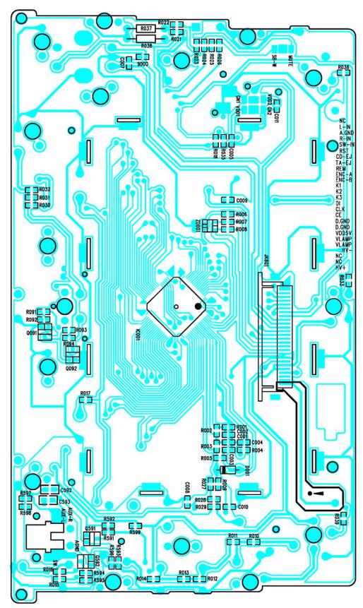
MAIN BOARD
BOTTOM VIEW
10
KEY BOARD
TOP VIEW
11
KEY BOARD
BOTTOM VIEW
12
 Loading...