

Page 1

OPERATING INSTRUCTION EXTERNAL BYPASS SWITCH
MBS 2000
MBS 3000
2
Page 2

1 General
The external, manually operated bypass unit is an option for
the PROTECT B., C. and C.R UPS series. It is used for
isolating the UPS, for example for maintenance purposes,
whilst the connected loads continue to be supplied without
interruption. Furthermore, an additional switch setting permits
UPS test operation.
Scope of delivery:
♦ External bypass unit MBS 2000 or MBS 3000
♦ 4 adhesive pads for attaching to the tower model
♦ 2 brackets for 19" rack mounting
♦ 4 screws for attaching the brackets to the bypass
♦ 2 connection cables to the UPS
♦ Operating instructions
Prerequisites:
♦ AEG PROTECT B., PROTECT C. or PROTECT C.R
UPS series
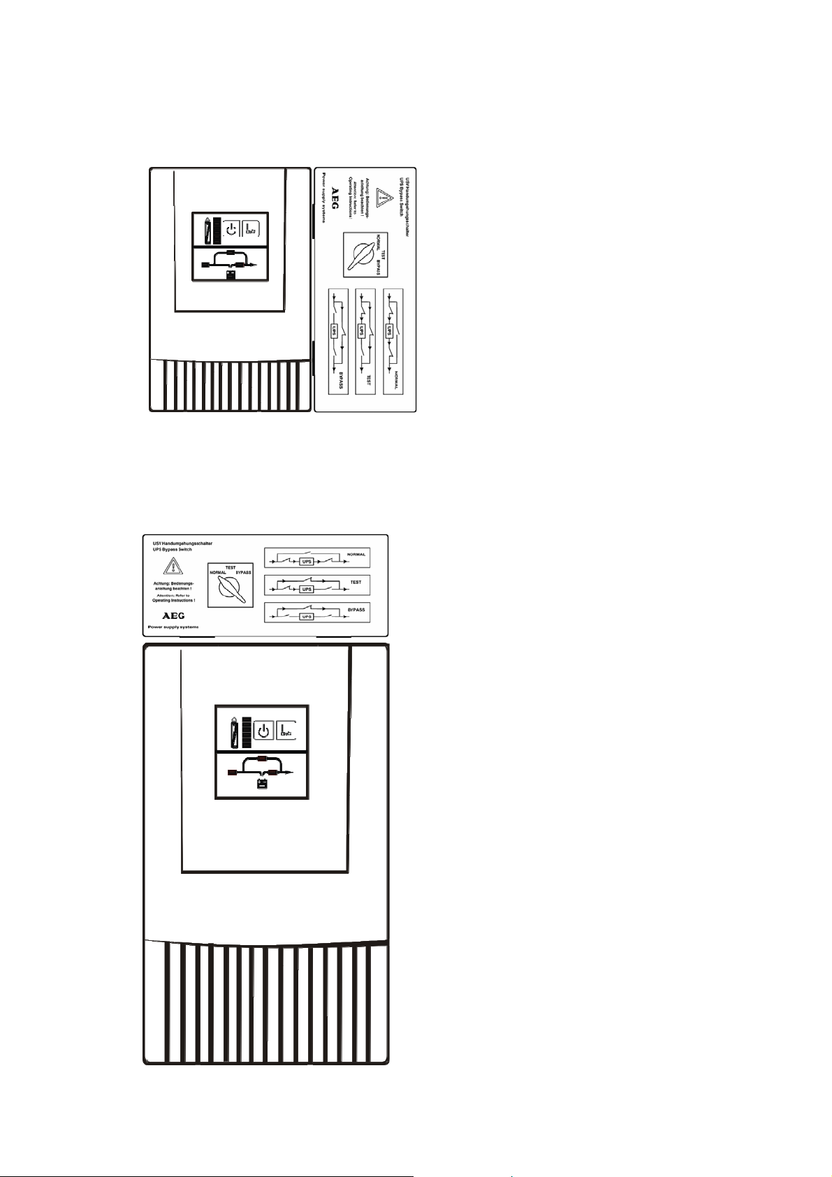
2 Description
The external bypass is used for changing over between:
"NORMAL" operation (default switch position),
i.e. secure load supply with UPS back-up.
"TEST" operation (service position),
i.e. load supply directly from the mains,
additional mains supply to the UPS for service purposes.
"BYPASS" operation (bypass position),
i.e. load supply directly from the mains,
additional complete isolation of the UPS
UPS output may still be live due to its internal
voltage source!
If there is a mains failure during "TEST" and "BYPASS"
operation then the supply to the connected loads will be
interrupted.
3
Page 3
3 Installation (mechanical)
Type MBS 2000
PROTECT B. 750 / B. 1000
PROTECT B. 1500 / B. 2000
PROTECT C. 1000 / C. 1000R
PROTECT C. 2000
Example: PROTECT C. 1000 with MBS 2000
Attach the external bypass to tower units with using the four
adhesive pads on the side of the UPS housing as shown in
the adjacent figure.
Type MBS 3000
PROTECT B. 3000
PROTECT C. 3000 / C. 3000R
Attach the external bypass to
more powerful tower units with
3000 VA using the four
adhesive pads on the top of the
UPS as shown in the adjacent
figure.
Example: PROTECT C. 3000 with MBS 3000
4
Page 4

r
The gluing points must be dry and free from
grease. The adhesive pads do not develop thei
full strength until after a curing time of approx. 24
hours. Do not apply any mechanical load to the
external bypass unit during this time. Press the
unit on firmly at the start.
PROTECT C.1000R / C.2000R / C.3000R / B. Rack version
For use in a rack, use the four screws supplied with the
bypass unit to attach the two supplied retaining brackets to
the sides of the unit.
During subsequent installation in the rack, take care that the
unit is located close to the UPS so as firstly to establish the
causal connection between the tw o and secondly to facilitate
connection and subsequent replacement of the UPS.
Example: PROTECT B.3000 with MBS 3000
5
Page 5

4 Connection (electrical)
If you have already taken the UPS into operatio n then switch
it off as the first step. Now disconnect the UPS from the mains
by disconnecting the mains connector.
Before you perform the installation described below, make
sure that none of the cables are live.
Make sure that the external bypass switch is in its default
position "NORMAL".
Rear view of MBS 2000 for unit types:
PROTECT B. 750
PROTECT B. 1000
PROTECT B. 1500
PROTECT B. 2000
PROTECT C. 1000
PROTECT C. 1000R
PROTECT C. 2000
PROTECT C. 2000R
6
Page 6

Rear view of MBS 3000 for unit types:
PROTECT B. 3000
PROTECT C. 3000
PROTECT C. 3000R
1. Connect the input of the external bypass to the mains
connection cable provided with the UPS and plug the
mains connector into a suitable shockpro of socket. In
particular in the case of high-capacity types, ensure
that the fusing in your sub-distribution is adequately
dimensioned: The 3 kVA system, for example,
requires its own connection with a 16 A fuse. No
other loads should be connected to this circuit!
Two connection cables are supplied with the external bypass.
Make the following connections:
2. Connect "OUTPUT" to the UPS output.
3. Connect "INPUT" to the UPS mains input.
4. As the last step, connect your loads . To do this, use
the load connection cables provided with the UPS.
This completes the installation and cabling of the UPS with
the external bypass unit. Now start up the UPS system in
accordance with the operating instructions.
7
Page 7

5 Wiring diagrams
UPS output
230V/N/PE~50/60Hz
L1 N
( NORMAL )
UPS operation
( BYPASS )
( TEST )
Service position
Manual bypass
PE L1 N
UPS input
230V/N/PE~50/60Hz
PE
L1
Mains
Loads
230V/N/PE~50/60Hz
230V/N/PE~50/60Hz
N
PEPEL1 N
8
Page 8

Guarantee Certificate
Type: ……………….………………………………....................
Serial-No: ………..……….………………………………………
Date of Purchase: ………......……..……………………………
Trading stamp /Signature
Specifications are subject to change without notice.
AEG Power Supply Systems GmbH
Emil-Siepmann-Straße 32
59581 Warstein-Belecke
Germany
Betriebsanleitung / Operating Instructions
BAL 8000014320-01 EN
AEG0306EN
9
 Loading...