


User Manual
TPC-31/61
3.5"/ 5.7" QVGA TFT LCD TI
Cortex-A8 Touch Panel
Computer

Copyright
The documentation and the software included with this product are copyrighted 2012 by Advantech Co., Ltd. All rights are reserved. Advantech Co., Ltd. reserves the right to make improvements in the products described in this manual at any time without notice. No part of this manual may be reproduced, copied, translated or transmitted in any form or by any means without the prior written permission of Advantech Co., Ltd. Information provided in this manual is intended to be accurate and reliable. However, Advantech Co., Ltd. assumes no responsibility for its use, nor for any infringements of the rights of third parties, which may result from its use.
Acknowledgements
IBM, PC/AT and VGA are trademarks of International Business Machines Corporation.
Microsoft Windows and MS-DOS are registered trademarks of Microsoft Corp. All other product names or trademarks are properties of their respective owners.
This Manual Covers the Following Models:
TPC-31T
TPC-61T
Part No. 2003003101 |
Edition 1 |
Printed in Taiwan |
July 2012 |
TPC-31/61 User Manual |
ii |

Product Warranty (2 years)
Advantech warrants to you, the original purchaser, that each of its products will be free from defects in materials and workmanship for two years from the date of purchase.
This warranty does not apply to any products which have been repaired or altered by persons other than repair personnel authorized by Advantech, or which have been subject to misuse, abuse, accident or improper installation. Advantech assumes no liability under the terms of this warranty as a consequence of such events.
Because of Advantech’s high quality-control standards and rigorous testing, most of our customers never need to use our repair service. If an Advantech product is defective, it will be repaired or replaced at no charge during the warranty period. For out- of-warranty repairs, you will be billed according to the cost of replacement materials, service time and freight. Please consult your dealer for more details.
If you think you have a defective product, follow these steps:
1.Collect all the information about the problem encountered. (For example, CPU speed, Advantech products used, other hardware and software used, etc.) Note anything abnormal and list any onscreen messages you get when the problem occurs.
2.Call your dealer and describe the problem. Please have your manual, product, and any helpful information readily available.
3.If your product is diagnosed as defective, obtain an RMA (return merchandize authorization) number from your dealer. This allows us to process your return more quickly.
4.Carefully pack the defective product, a fully-completed Repair and Replacement Order Card and a photocopy proof of purchase date (such as your sales receipt) in a shippable container. A product returned without proof of the purchase date is not eligible for warranty service.
5.Write the RMA number visibly on the outside of the package and ship it prepaid to your dealer.
Declaration of Conformity
CE
This product has passed the CE test for environmental specifications.
FCC Class A
Note: This equipment has been tested and found to comply with the limits for a Class A digital device, pursuant to part 15 of the FCC Rules. These limits are designed to provide reasonable protection against harmful interference when the equipment is operated in a commercial environment. This equipment generates, uses, and can radiate radio frequency energy and, if not installed and used in accordance with the instruction manual, may cause harmful interference to radio communications. Operation of this equipment in a residential area is likely to cause harmful interference in which case the user will be required to correct the interference at his own expense.
iii |
TPC-31/61 User Manual |
Technical Support and Assistance
1.Visit the Advantech web site at www.advantech.com/support where you can find the latest information about the product.
2.Contact your distributor, sales representative, or Advantech's customer service center for technical support if you need additional assistance. Please have the following information ready before you call:
–Product name and serial number
–Description of your peripheral attachments
–Description of your software (operating system, version, application software, etc.)
–A complete description of the problem
–The exact wording of any error messages
Warnings, Cautions and Notes
Warning! Warnings indicate conditions, which if not observed, can cause personal injury!
Caution! Cautions are included to help you avoid damaging hardware or losing data. e.g.
There is a danger of a new battery exploding if it is incorrectly installed. Do not attempt to recharge, force open, or heat the battery. Replace the battery only with the same or equivalent type recommended by the manufacturer. Discard used batteries according to the manufacturer's instructions.
Note! Notes provide optional additional information.
TPC-31/61 User Manual |
iv |

Safety Instructions
1.Read these safety instructions carefully.
2.Keep this User Manual for later reference.
3.Disconnect this equipment from any AC outlet before cleaning. Use a damp cloth. Do not use liquid or spray detergents for cleaning.
4.For plug-in equipment, the power outlet socket must be located near the equipment and must be easily accessible.
5.Keep this equipment away from humidity.
6.Put this equipment on a reliable surface during installation. Dropping it or letting it fall may cause damage.
7.The openings on the enclosure are for air convection. Protect the equipment from overheating. DO NOT COVER THE OPENINGS.
8.Make sure the voltage of the power source is correct before connecting the equipment to the power outlet.
9.Position the power cord so that people cannot step on it. Do not place anything over the power cord.
10.All cautions and warnings on the equipment should be noted.
11.If the equipment is not used for a long time, disconnect it from the power source to avoid damage by transient overvoltage.
12.Never pour any liquid into an opening. This may cause fire or electrical shock.
13.Never open the equipment. For safety reasons, the equipment should be opened only by qualified service personnel.
14.If one of the following situations arises, get the equipment checked by service personnel:
a.The power cord or plug is damaged. b.Liquid has penetrated into the equipment.
c.The equipment has been exposed to moisture.
d.The equipment does not work well, or you cannot get it to work according to the user's manual.
e.The equipment has been dropped and damaged. f.The equipment has obvious signs of breakage.
15.DO NOT LEAVE THIS EQUIPMENT IN AN ENVIRONMENT WHERE THE STORAGE TEMPERATURE MAY GO BELOW -20° C (-4° F) OR ABOVE 70° C (158° F). THIS COULD DAMAGE THE EQUIPMENT. THE EQUIPMENT SHOULD BE IN A CONTROLLED ENVIRONMENT.
16.CAUTION: DANGER OF EXPLOSION IF BATTERY IS INCORRECTLY REPLACED. REPLACE ONLY WITH THE SAME OR EQUIVALENT TYPE RECOMMENDED BY THE MANUFACTURER, DISCARD USED BATTERIES ACCORDING TO THE MANUFACTURER'S INSTRUCTIONS.
v |
TPC-31/61 User Manual |

Wichtige Sicherheishinweise
1.Bitte lesen sie Sich diese Hinweise sorgfältig durch.
2.Heben Sie diese Anleitung für den späteren Gebrauch auf.
3.Vor jedem Reinigen ist das Gerät vom Stromnetz zu trennen. Verwenden Sie Keine Flüssig-oder Aerosolreiniger. Am besten dient ein angefeuchtetes Tuch zur Reinigung.
4.Die NetzanschluBsteckdose soll nahe dem Gerät angebracht und leicht zugänglich sein.
5.Das Gerät ist vor Feuchtigkeit zu schützen.
6.Bei der Aufstellung des Gerätes ist auf sicheren Stand zu achten. Ein Kippen oder Fallen könnte Verletzungen hervorrufen.
7.Die Belüftungsöffnungen dienen zur Luftzirkulation die das Gerät vor überhitzung schützt. Sorgen Sie dafür, daB diese Öffnungen nicht abgedeckt werden.
8.Beachten Sie beim. AnschluB an das Stromnetz die AnschluBwerte.
9.Verlegen Sie die NetzanschluBleitung so, daB niemand darüber fallen kann. Es sollte auch nichts auf der Leitung abgestellt werden.
10.Es sollte auch nichts auf der Leitung abgestellt werden. Alle Hinweise und Warnungen die sich am Ger?ten befinden sind zu beachten.
11.Wird das Gerät über einen längeren Zeitraum nicht benutzt, sollten Sie es vom Stromnetz trennen. Somit wird im Falle einer Überspannung eine Beschädigung vermieden.
12.Durch die Lüftungsöffnungen dürfen niemals Gegenstände oder Flüssigkeiten in das Gerät gelangen. Dies könnte einen Brand bzw. elektrischen Schlag auslösen.
13.Öffnen Sie niemals das Gerät. Das Gerät darf aus Gründen der elektrischen Sicherheit nur von authorisiertem Servicepersonal geöffnet werden.
14.Wenn folgende Situationen auftreten ist das Gerät vom Stromnetz zu trennen und von einer qualifizierten Servicestelle zu überprüfen:
a.Netzkabel oder Netzstecker sind beschädigt. b.Flüssigkeit ist in das Gerät eingedrungen. c.Das Gerät war Feuchtigkeit ausgesetzt.
d.Wenn das Gerät nicht der Bedienungsanleitung entsprechend funktioniert oder Sie mit Hilfe dieser Anleitung keine Verbesserung erzielen.
TPC-31/61 User Manual |
vi |

Contents
Chapter |
1 |
General Information ............................ |
1 |
||
|
1.1 |
Introduction ............................................................................................... |
|
2 |
|
|
1.2 |
Specifications ............................................................................................ |
|
2 |
|
|
|
1.2.1 |
System Kernel............................................................................... |
2 |
|
|
|
1.2.2 |
I/O Ports........................................................................................ |
|
2 |
|
|
1.2.3 |
Storage ......................................................................................... |
|
2 |
|
|
1.2.4 |
Safety and Environment................................................................ |
3 |
|
|
|
1.2.5 |
LCD Specifications........................................................................ |
3 |
|
|
|
1.2.6 |
Touchscreen Specifications .......................................................... |
3 |
|
|
|
1.2.7 |
Power............................................................................................ |
|
3 |
|
|
1.2.8 |
I/O Ports Arrangement .................................................................. |
4 |
|
|
|
|
Figure 1.1 |
TPC-31T I/O Ports Arrangement ................................ |
4 |
|
|
|
Figure 1.2 |
TPC-61T I/O Ports Arrangement ................................ |
4 |
|
1.3 |
Panel Mounting ......................................................................................... |
|
5 |
|
|
|
|
Figure 1.3 |
Panel Mounting........................................................... |
5 |
|
1.4 |
Dimensions and Cutout............................................................................. |
6 |
||
|
|
|
Figure 1.4 |
TPC-31T Dimensions and Cutout............................... |
6 |
|
|
|
Figure 1.5 |
TPC-61T Dimensions and Cutout............................... |
6 |
Chapter 2 |
System Setup....................................... |
7 |
|
2.1 |
System Setup............................................................................................ |
|
8 |
|
Figure 2.1 |
Power Connector and Power Lines ............................ |
8 |
|
Figure 2.2 |
Pin Assignment on the Power Receptor..................... |
8 |
|
Figure 2.3 |
Power Line into the Power Receptor .......................... |
9 |
Chapter |
3 |
System Tuning................................... |
11 |
|
|
3.1 |
LCD Tuning ............................................................................................. |
|
12 |
|
|
Figure 3.1 |
Display...................................................................... |
12 |
|
|
Figure 3.2 |
Display Properties .................................................... |
12 |
|
3.2 |
Touchscreen Calibration ......................................................................... |
13 |
|
|
|
Figure 3.3 |
Style.......................................................................... |
13 |
|
|
Figure 3.4 |
Stylus Properties ...................................................... |
13 |
|
|
Figure 3.5 |
Touchscreen Calibration........................................... |
14 |
|
3.3 |
Buzzer Setting......................................................................................... |
|
14 |
|
|
Figure 3.6 |
Volume & Sounds Settings 1.................................... |
14 |
|
|
Figure 3.7 |
Volume & Sounds Settings 2.................................... |
14 |
Chapter |
4 |
Windows CE....................................... |
17 |
||
|
4.1 |
Windows CE............................................................................................ |
|
18 |
|
|
|
|
Figure 4.1 |
Windows CE on TPC-31/61...................................... |
18 |
|
4.2 |
TPC Utilities ............................................................................................ |
|
19 |
|
|
|
4.2.1 |
Soft-Keyboard ............................................................................. |
19 |
|
|
|
|
Figure 4.2 |
Soft-Keyboard........................................................... |
19 |
|
|
4.2.2 |
TPC Configuration ...................................................................... |
19 |
|
|
|
|
Figure 4.3 |
TPC Configurator...................................................... |
19 |
|
|
|
Figure 4.4 |
General..................................................................... |
20 |
|
|
|
Figure 4.5 |
Network .................................................................... |
20 |
|
|
|
Figure 4.6 |
Advanced Network ................................................... |
21 |
|
|
|
Figure 4.7 |
Watchdog Setting ..................................................... |
21 |
|
|
|
|
vii |
TPC-31/61 User Manual |

|
|
Figure 4.8 |
Misc Page................................................................. |
22 |
|
|
Figure 4.9 |
Reboot Machine ....................................................... |
22 |
|
|
Figure 4.10Registry Saving Success.......................................... |
23 |
|
|
|
Figure 4.11Registry Editor.......................................................... |
23 |
|
|
4.2.3 |
Advantech Tools ......................................................................... |
24 |
|
|
|
Figure 4.12Advantech Tools....................................................... |
24 |
|
|
|
Figure 4.13NotepadPlus............................................................. |
25 |
|
|
|
Figure 4.14TPC Version Information .......................................... |
25 |
|
|
4.2.4 |
Other Utilities .............................................................................. |
26 |
|
4.3 |
Networking .............................................................................................. |
|
26 |
|
|
4.3.1 |
Network via Ethernet .................................................................. |
26 |
|
|
|
Figure 4.15Network and Dial-up Connections............................ |
26 |
|
|
|
Figure 4.16Selected Connection ................................................ |
27 |
|
|
|
Figure 4.17Setting IP Address.................................................... |
27 |
|
|
|
Figure 4.18Settng Name Servers ............................................... |
28 |
|
|
|
Figure 4.19Save Registry ........................................................... |
28 |
|
|
4.3.2 Network via Serial Port ............................................................... |
29 |
||
|
|
Figure 4.20PC Connection ......................................................... |
29 |
|
|
|
Figure 4.21PC Connection Properties........................................ |
30 |
|
|
|
Figure 4.22Change Connection.................................................. |
30 |
|
|
|
Figure 4.23Change Connection.................................................. |
31 |
|
|
|
Figure 4.24COM1 Set................................................................. |
31 |
|
|
|
Figure 4.25Microsoft ActiveSync ................................................ |
31 |
|
|
|
Figure 4.26Select Connection Setting ........................................ |
32 |
|
|
|
Figure 4.27Configure Connection Setting .................................. |
32 |
|
|
|
Figure 4.28Get Connected ......................................................... |
33 |
|
|
|
Figure 4.29Run Repllog.exe on the TPC.................................... |
33 |
|
|
|
Figure 4.30Connection on the TPC ............................................ |
34 |
|
|
|
Figure 4.31Connection on the Host PC...................................... |
34 |
|
|
|
Figure 4.32Explore the TPC ....................................................... |
35 |
|
4.4 |
Application Program Development ......................................................... |
35 |
||
|
4.4.1 System Requirements for Developers ........................................ |
35 |
||
|
4.4.2 Building Windows CE Runtime ................................................... |
36 |
||
|
|
Figure 4.33Starting a New Project.............................................. |
36 |
|
|
|
Figure 4.34Selecting................................................................... |
37 |
|
|
|
Figure 4.35Compiling Your Program .......................................... |
37 |
|
Appendix A |
Watchdog Timer Programming ....... |
39 |
|
A.1 |
Device IO Control.................................................................................... |
40 |
|
A.2 |
How to Use the Control Code ................................................................. |
41 |
|
|
A.2.1 |
IOCTL _WDT_ENABLE:............................................................. |
41 |
|
A.2.2 |
IOCTL _WDT_DISABLE:............................................................ |
41 |
|
A.2.3 IOCTL_WDT_STROBE: ............................................................. |
41 |
|
|
A.2.4 IOCTL_WDT_GETTIMEOUT: .................................................... |
41 |
|
|
A.2.5 IOCTL_WDT_SETTIMEOUT:..................................................... |
42 |
|
|
A.2.6 IOCTL_WDT_REBOOT:............................................................. |
42 |
|
A.3 |
Examples ................................................................................................ |
42 |
|
Appendix B |
Fuse Specifications .......................... |
45 |
|
B.1 |
Fuse Specifications................................................................................. |
46 |
|
Appendix C |
Pin Assignments............................... |
47 |
|
C.1 |
RS-232 |
Pin Assignments-TPC-31/TPC-61 (COM1,COM2).................... |
48 |
C.2 |
RS-485 |
Pin Assignment - TPC-31 .......................................................... |
48 |
C.3 |
RS422(COM3) Pin assignment - TPC-61 ............................................... |
49 |
|
TPC-31/61 User Manual |
|
viii |
|

C.4 |
CAN Pin assignment - TPC-31 ............................................................... |
49 |
|
Appendix D |
Visual Settings................................... |
51 |
|
D.1 |
Font Setting............................................................................................. |
52 |
|
|
|
Figure D.1 Font Setting .............................................................. |
52 |
|
|
Figure D.2 Small Font Setting .................................................... |
52 |
|
|
Figure D.3 Change Font Setting................................................. |
53 |
|
|
Figure D.4 Small Font Display.................................................... |
53 |
D.2 |
Screen Rotation ...................................................................................... |
54 |
|
|
|
Figure D.5 Screen Rotation........................................................ |
54 |
|
|
Figure D.6 Screen Rotation Options .......................................... |
54 |
|
|
Figure D.7 90 Degrees Rotation................................................. |
55 |
|
|
Figure D.8 Portrait Rotation........................................................ |
55 |
Appendix E TPC-31T /61T Update Guide ............. |
57 |
||
E.1 |
Updating Image & Bootloader ................................................................. |
58 |
|
Appendix F |
Jumper & Dip Switch Setting List .... |
61 |
|
F.1 |
TPC-31T Component construction.......................................................... |
62 |
|
|
F.1.1 |
EAMB-2201 Top side.................................................................. |
62 |
F.2 |
Jumper Setting DIP Switch ..................................................................... |
63 |
|
F.3 |
TPC-61T Component construction.......................................................... |
64 |
|
|
F.3.1 |
EAMB-2200 Top side.................................................................. |
64 |
|
F.3.2 |
EAMB-2200 Bottom side............................................................. |
64 |
F.4 |
Jumper Setting DIP Switch ..................................................................... |
65 |
|
|
F.4.1 SW3 UART Controlled Function ................................................. |
65 |
|
ix |
TPC-31/61 User Manual |

TPC-31/61 User Manual |
x |
Chapter 1
1 General Information
This chapter gives background information for the TPC-31/61 series.
Sections include:
Introduction
Specifications
LCD Specifications
Touchscreen Specifications
Power
I/O Port Arrangement
Mounting
Dimensions and Cutout

1.1 Introduction
The TPC-31/61 series of touch panel computers consist of state-of-the-art HMI (Human Machine Interfaces). The 3.5"/5.7” operator interface combined with a RISCbased computing platform offers these key features:
Bright Display:The high-brightness LCD display provides a clear interface.
Fanless: By using a low power processor, the system does not have to rely on fans, which often are unreliable, and attracts dust.
Powerful Communication Capability:
The TPC-31/61 series provides a powerful I/O interface for easy communication with other devices. The I/O interface includes serial ports, RS-485 port, Ethernet and USB. (Serial Port default as RS-232)
Windows CE Support: Advantech offers platform support for Windows CE. The optional Windows CE operating system specifically for the TPC-31/61 is available for Windows CE application program builders.
1.2Specifications
1.2.1System Kernel
CPU: TI Cortex-A8 AM3517 600 MHz
Memory: DDR2 256MB on board
Storage Memory: 512MB on board micro SD card;1Mb FRAM for Data back-up
Ethernet: 10/100Base-T x 1
Watchdog Timer: Programmable as 250 ms, 500 ms, 1 second
SD Slot: Secure Digital Slot
1.2.2I/O Ports
TPC-31T:
RS-232/RS-485 X1 with auto data flow control, USB 2.0(Host) x 1, CAN bus x 1
TPC-61T:
RS-232 x 2 (COM1,2)RS-422/RS-485 x1 (COM 3) with auto data flow control, USB2.0 (Host) x 1, USB2.0 (Client) x 1
1.2.3Storage
TPC-31/61 panel computers provide two methods for storage. One is the on-board 512MB micro SD card and the other one is an external SD card.
TPC-31/61 User Manual |
2 |

1.2.4 Safety and Environment
Safety
FCC Class A, CE, BSMI, UL certified
The front bezel is compliant with NEMA 4/ IP65
Environment
Operating Temperature: 0~50°C (32 ~ 122°F)
Storage Temperature: -20 ~ 60°C (-4 ~ 140°F)
Humidity: 10~95% @ 40°C relative humidity (non-condensing)
Vibration: 1 Grms (Random, Operating)
1.2.5LCD Specifications
|
TPC-31/61 |
Display Type |
TFT LCD |
Size (diagonal) |
3.5”/5.7” |
Maximum Resolution |
320 x 240 (QVGA) |
Maximum Colors |
64K |
Viewing Angle |
120/110; 160/140 |
Luminance (cd / m2) |
450/800 |
Contrast Ratio |
300:1 / 800:1 |
Backlight |
LED |
Backlight MTBF |
30000 / 50000hrs |
1.2.6 Touchscreen Specifications
Touch Type |
Resistive |
Base Glass Construction |
Glass |
Resolution |
Continuous |
Light Transmission |
80% typical |
Software Driver |
Windows CE (embedded) |
Durability |
1 million times with a 8 mm diameter silicone rubber finger |
Note! There is no pointer/cursor shown using the touch screen. The cursor only appears when closing or minimizing the window.
1.2.7Power
Input Voltage: 18~32 VDC
Maximum Current: 1 A
<![endif]>Information General 1 Chapter
3 |
TPC-31/61 User Manual |
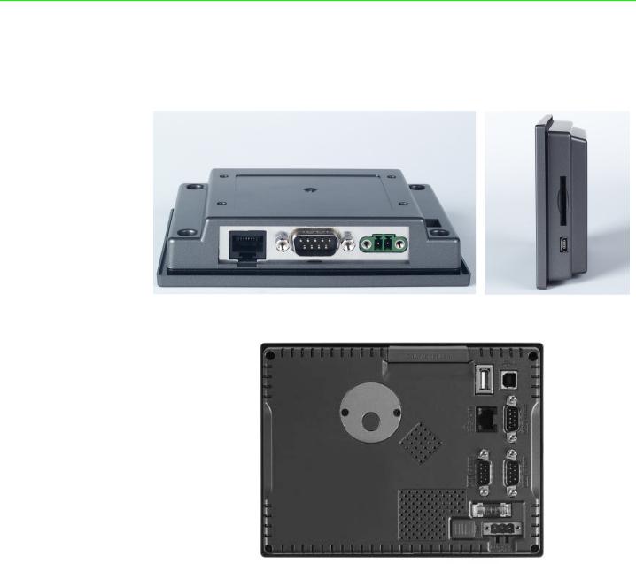
1.2.8 I/O Ports Arrangement
TPC-31T provides 1 serial port, 1 Ethernet LAN port and 1 USB port. While TPC-61T provides 3 serial ports, 1 Ethernet LAN, 2 USB port(1xHost, 1xClient).
Figure 1.1 TPC-31T I/O Ports Arrangement
Figure 1.2 TPC-61T I/O Ports Arrangement
TPC-31/61 User Manual |
4 |

1.3 Panel Mounting
There is an adhesive waterproof gasket on the front bezel. Make sure the waterproof gasket is in position before installing a TPC-31/61 panel computer into the panel opening.
TPC-31T:
1.Install the panel computer into the panel opening.
2.Find the mount bracket, four short screws and four long screws in the accessory pack. Fix the mount bracket on the rear cover with four short screws and then fasten the long screws. These screws will then push the mounting panel and fix the unit. The mounting panel thickness is suggested to be less than 3.5 mm (0.137 inch).
TPC-61T:
1.Install the TPC into the panel opening.
2.Find the six clamps and six long screws in the accessory pack. Hook the clamps to the holes around the four sides of the bezel. Insert the screws into every clamp and fasten them. These screws will push the mounting panel and fix the unit.
3.The suggested mounting panel thickness is less than 6 mm (0.236”).
Figure 1.3 Panel Mounting
<![endif]>Information General 1 Chapter
5 |
TPC-31/61 User Manual |
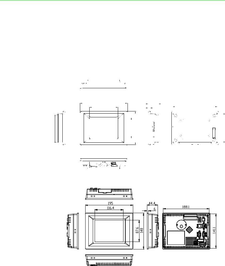
1.4Dimensions and Cutout
Weight:
TPC-31T: 0.25 kg (0.55 lbs) TPC-61T: 0.8 kg (1.76 lb)
Dimensions (WxHxD):
TPC-31T: 120.79 x 85.5 x 26.5 mm (4.76" x 3.37" x 1.04") TPC-61T: 195 x 148 x 44.4 mm (7.68" x 5.83" x 1.75")
Cutout:
TPC-31T: 115 x 79.5 mm TPC-61T: 189 x 142 mm
121 |
|
26.5 |
|
|
114.1 |
|
72.7 |
5 |
|
|
|
||
|
| <![if ! IE]> <![endif]>54.3 |
|
<![if ! IE]> <![endif]>85.5 |
|
|
|
|
|
|
|
|
|
|
|
|
|
|
|
|
|
|
|
|
|
|
|
|
|
|
|
|
|
|
|
|
|
|
|
|
|
<![if ! IE]> <![endif]>78.6 |
|||
|
|
|
|
|
|
|
|
|
|
|
|
|
|
|
|
|
|
||||
|
|
|
|
|
|
|
|
|
|
|
|
|
|
|
|
|
|
||||
|
|
|
|
|
|
|
|
|
|
|
|
|
|
|
|
|
|
||||
|
|
|
|
|
|
|
|
|
|
|
|
|
|
|
|
|
|
||||
|
|
|
|
|
|
|
|
|
|
|
|
|
|
|
|
|
|
||||
|
|
|
|
|
|
|
|
|
|
|
|
|
|
|
|
|
|
||||
|
|
|
|
||||||||||||||||||
|
|
|
|
|
|
|
|
|
|
|
|
|
|
|
|
|
|
|
|
|
|
|
|
|
|
|
|
|
|
|
|
|
|
|
|
|
|
|
|
|
|
|
|
|
|
|
|
|
|
|
|
|
|
|
|
|
|
|
|
|
|
|
|
|
|
|
|
|
|
|
|
|
|
|
|
|
|
|
|
|
|
|
|
|
|
|
|
|
|
|
|
|
|
|
|
|
|
|
|
|
|
|
|
|
|
|
|
|
|
|
|
|
|
|
|
|
|
|
|
|
|
|
|
|
|
|
|
|
|
|
|
|
|
|
|
|
|
|
|
|
|
|
|
|
|
|
|
|
|
|
|
|
|
Figure 1.4 TPC-31T Dimensions and Cutout
Figure 1.5 TPC-61T Dimensions and Cutout
TPC-31/61 User Manual |
6 |

Chapter 2
2 System Setup
This chapter provides a brief explanation for operating the TPC31/61.
2.1 System Setup
You can quickly get up and running by following the step-by-step instructions below.
1.Open the package. check the packing list at the beginning of this manual to make sure every item is there.
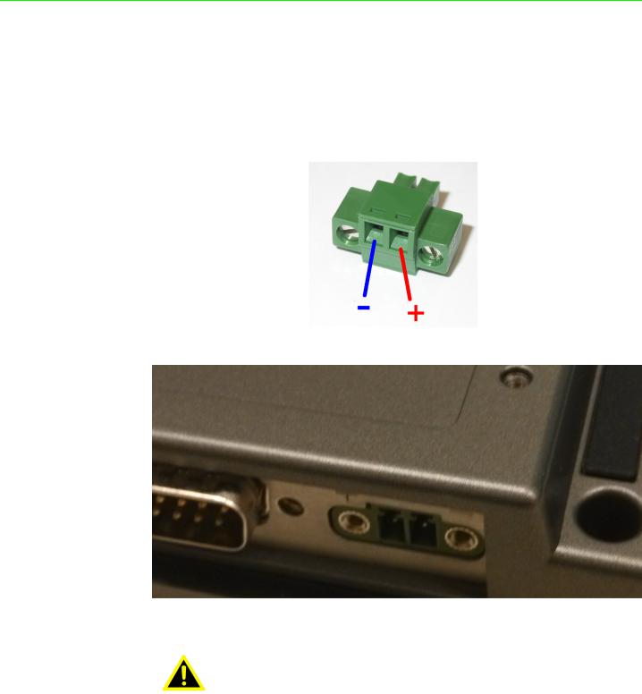
2.Connect the power connector to the 18~32 VDC power lines. The power lines can either be from some power adapter or an in-house power source.
Figure 2.1 Power Connector and Power Lines
Figure 2.2 Pin Assignment on the Power Receptor
Warning! The system may be damaged when the power is turned on if the power source is not connected to the correct pins.
TPC-31/61 User Manual |
8 |

3.Plug the power lines into the system power receptor. Thus the system will turn on.
Figure 2.3 Power Line into the Power Receptor
4.Turn on the System
5.Calibrate the touchscreen.
<![endif]>Setup System 2 Chapter
9 |
TPC-31/61 User Manual |

TPC-31/61 User Manual |
10 |
Chapter 3
3 System Tuning
Sections include:
LCD Contrast Tuning
Touchscreen Calibration
Buzzer Setting

3.1 LCD Tuning
The display settings let you control the backlight. Backlight provides a screen saving function. The backlight can be automatically turned off when the device is no longer used to lengthen the device life. Go to “Start” -> “Setting” -> “Control Panel” -> “Display” as shown in the Figure below.
Figure 3.1 Display
To set the time to automatically turn off, tick the check box “turn off backlight” and set the time to elapse by inputting a number in the edit box.
Figure 3.2 Display Properties
TPC-31/61 User Manual |
12 |

3.2 Touchscreen Calibration
You can calibrate the touchscreen through “Start” -> “Setting” -> “Control Panel” -> “Stylus” as shown in the Figure below.
Figure 3.3 Style
The window of the stylus properties will display after you click the stylus. There are two tabs in this screen: Double-Tap and Calibration. Double-Tap is used to record the time period between the two taps when double-tapping in Windows CE. Calibration is for users to calibrate the touch screen.
Figure 3.4 Stylus Properties
<![endif]>Tuning System 3 Chapter
13 |
TPC-31/61 User Manual |
 Loading...