


 Loading...
TPC-1261H
GX3 LX800 Touch Panel Computer with 12.1" SVGA TFT LCD
User Manual
Copyright
The documentation and the software included with this product are copyrighted 2004 by Advantech Co., Ltd. All rights are reserved. Advantech Co., Ltd. reserves the right to make improvements in the products described in this manual at any time without notice. No part of this manual may be reproduced, copied, translated or transmitted in any form or by any means without the prior written permission of Advantech Co., Ltd. Information provided in this manual is intended to be accurate and reliable. However, Advantech Co., Ltd. assumes no responsibility for its use, nor for any infringements of the rights of third parties, which may result from its use.
Acknowledgements
Intel and Pentium are trademarks of Intel Corporation. Microsoft Windows and MS-DOS are registered trademarks of Microsoft Corp.
All other product names or trademarks are properties of their respective owners.
This Manual Covers the Following Models
•TPC-1261H-A1
•TPC-1261H-A1E
Part No. 2003126120 |
1st Edition |
Printed in Taiwan |
May 2006 |
TPC-1261H User Manual |
ii |
Product Warranty (1 year)
Advantech warrants to you, the original purchaser, that each of its products will be free from defects in materials and workmanship for one year from the date of purchase.
This warranty does not apply to any products which have been repaired or altered by persons other than repair personnel authorized by Advantech, or which have been subject to misuse, abuse, accident or improper installation. Advantech assumes no liability under the terms of this warranty as a consequence of such events.
Because of Advantech’s high quality-control standards and rigorous testing, most of our customers never need to use our repair service. If an Advantech product is defective, it will be repaired or replaced at no charge during the warranty period. For out-of-warranty repairs, you will be billed according to the cost of replacement materials, service time and freight. Please consult your dealer for more details.
If you think you have a defective product, follow these steps:
1.Collect all the information about the problem encountered. (For example, CPU speed, Advantech products used, other hardware and software used, etc.) Note anything abnormal and list any onscreen messages you get when the problem occurs.
2.Call your dealer and describe the problem. Please have your manual, product, and any helpful information readily available.
3.If your product is diagnosed as defective, obtain an RMA (return merchandize authorization) number from your dealer. This allows us to process your return more quickly.
4.Carefully pack the defective product, a fully-completed Repair and Replacement Order Card and a photocopy proof of purchase date (such as your sales receipt) in a shippable container. A product returned without proof of the purchase date is not eligible for warranty service.
5.Write the RMA number visibly on the outside of the package and ship it prepaid to your dealer.
iii
CE
This product has passed the CE test for environmental specifications when shielded cables are used for external wiring. We recommend the use of shielded cables. This kind of cable is available from Advantech. Please contact your local supplier for ordering information.
FCC Class A
This equipment has been tested and found to comply with the limits for a Class A digital device, pursuant to Part 15 of the FCC Rules. These limits are designed to provide reasonable protection against harmful interference when the equipment is operated in a commercial environment. This equipment generates, uses and can radiate radio frequency energy and, if not installed and used in accordance with the instruction manual, may cause harmful interference to radio communications. Operation of this equipment in a residential area is likely to cause harmful interference in which case the user will be required to correct the interference at his own expense.
Technical Support and Assistance
Step 1. Visit the Advantech web site at www.advantech.com/support where you can find the latest information about the product.
Step 2. Contact your distributor, sales representative, or Advantech's customer service center for technical support if you need additional assistance. Please have the following information ready before you call:
-Product name and serial number
-Description of your peripheral attachments
-Description of your software (operating system, version, application software, etc.)
-A complete description of the problem
-The exact wording of any error messages
TPC-1261H User Manual |
iv |
Packing List
Before setting up the system, check that the items listed below are included and in good condition. If any item does not accord with the table, please contact your dealer immediately.
•1 x TPC-1261H-A1
•8 x Panel mounting clampers
•8 x Panel mounting screws
•1 x 3-Pin power connector
•1 x TPC x86 Series support CD
•1 x CompactFlash to IDE adapter board
Safety Instructions
1.Read these safety instructions carefully.
2.Keep this User's Manual for later reference.
3.Disconnect this equipment from any AC outlet before cleaning. Use a damp cloth. Do not use liquid or spray detergents for cleaning.
4.For plug-in equipment, the power outlet socket must be located near the equipment and must be easily accessible.
5.Keep this equipment away from humidity.
6.Put this equipment on a reliable surface during installation. Dropping it or letting it fall may cause damage.
7.The openings on the enclosure are for air convection. Protect the equipment from overheating. DO NOT COVER THE OPENINGS.
8.Make sure the voltage of the power source is correct before connecting the equipment to the power outlet.
9.Position the power cord so that people cannot step on it. Do not place anything over the power cord.
10.All cautions and warnings on the equipment should be noted.
11.If the equipment is not used for a long time, disconnect it from the power source to avoid damage by transient overvoltage.
12.Never pour any liquid into an opening. This may cause fire or electrical shock.
v
13.Never open the equipment. For safety reasons, the equipment should be opened only by qualified service personnel.
14.If one of the following situations arises, get the equipment checked by service personnel:
a.The power cord or plug is damaged.
b.Liquid has penetrated into the equipment.
c.The equipment has been exposed to moisture.
d.The equipment does not work well, or you cannot get it to work according to the user's manual.
e.The equipment has been dropped and damaged.
f.The equipment has obvious signs of breakage.
15.DO NOT LEAVE THIS EQUIPMENT IN AN ENVIRONMENT WHERE THE STORAGE TEMPERATURE MAY GO BELOW - 20° C (-4° F) OR ABOVE 60° C (140° F). THIS COULD DAMAGE THE EQUIPMENT. THE EQUIPMENT SHOULD BE IN A CONTROLLED ENVIRONMENT.
16.CAUTION: DANGER OF EXPLOSION IF BATTERY IS INCORRECTLY REPLACED. REPLACE ONLY WITH THE SAME OR EQUIVALENT TYPE RECOMMENDED BY THE MANUFACTURER, DISCARD USED BATTERIES ACCORD-
ING TO THE MANUFACTURER'S INSTRUCTIONS.
The sound pressure level at the operator's position according to IEC 704- 1:1982 is no more than 70 dB (A).
DISCLAIMER: This set of instructions is given according to IEC 704-1. Advantech disclaims all responsibility for the accuracy of any statements contained herein.
TPC-1261H User Manual |
vi |
Contents
Chapter |
1 |
General Information ....................................... |
2 |
|
|
1.1 |
Introduction ....................................................................... |
2 |
|
|
1.2 |
Specifications .................................................................... |
3 |
|
|
|
1.2.1 |
System Kernel ................................................................ |
3 |
|
|
1.2.2 |
I/O Ports ......................................................................... |
3 |
|
|
1.2.3 |
Safety and Environment ................................................. |
3 |
|
1.3 |
LCD Specifications ........................................................... |
4 |
|
|
1.4 |
Touchscreen Specifications............................................... |
4 |
|
|
1.5 |
Power |
................................................................................. |
5 |
|
1.6 |
I/O Ports Arrangement ...................................................... |
5 |
|
|
|
|
Figure 1.1:I/O Port Arrangement ................................... |
5 |
|
1.7 |
Panel Mounting ................................................................. |
5 |
|
|
|
............................................ |
Figure 1.2:Panel Mounting |
6 |
|
1.8 |
Dimensions .....................................................and Cutout |
6 |
|
|
|
................................................... |
Figure 1.3:Dimensions |
7 |
Chapter |
2 System Setup.................................................. |
10 |
|
Figure 2.1:Unpack the Package ................................... |
10 |
|
Figure 2.2:Install CompactFlash Memory Card .......... |
11 |
|
Figure 2.3:Power Connector and Power Lines ............ |
11 |
|
Figure 2.4:Power Receptor & Button Pin Assignment 11 |
|
|
Figure 2.5:Touchscreen Icon ....................................... |
12 |
|
Figure 2.6:Touchscreen Calibration ............................ |
12 |
Chapter 3 System Engine................................................ |
14 |
Table 3.1:Mainboard Connectors & Jumper Settings . 14 |
|
Figure 3.1:Main Board Connectors - 1 ........................ |
15 |
Figure 3.2:Main Board Connectors - 2 ........................ |
15 |
Chapter 4 |
Software Configuration ................................ |
18 |
4.1 |
VGA Driver Installation.................................................. |
18 |
|
Figure 4.1:Device Manager ......................................... |
18 |
|
Figure 4.2:Update Driver ............................................. |
19 |
|
Figure 4.3:Update Wizard-1 ....................................... |
19 |
|
Figure 4.4:Update Wizard-2 ........................................ |
20 |
|
Figure 4.5:Update Wizard-3 ....................................... |
20 |
|
Figure 4.6:Update Wizard-4 ........................................ |
21 |
|
Figure 4.7:Update Wizard-5 ....................................... |
21 |
|
Figure 4.8:Update Wizard-6 ........................................ |
22 |
|
Figure 4.9:Driver Installation Complete ...................... |
22 |
4.2 Advantech COM Driver Install ....................................... |
23 |
|
|
Figure 4.10:PCI_ICOM Setup ..................................... |
23 |
|
Figure 4.11:PCI ICOM Installation - 1 ....................... |
23 |
|
Figure 4.12:PCI ICOM Installation - 2 ........................ |
24 |
|
Figure 4.13:Device Manager Screen ........................... |
24 |
vii |
Table of Contents |
|
|
|
Figure 4.14:Update Driver - 1 ...................................... |
25 |
|
|
|
|
Figure 4.15:Update Driver - 2 ...................................... |
25 |
|
|
|
|
Figure 4.16:Update Driver - 3 ...................................... |
26 |
|
|
|
|
Figure 4.17:Slave Bridge Installation Complete .......... |
26 |
|
|
|
|
Figure 4.18:PCI - 1602 Device Manager ....................... |
27 |
|
|
|
|
Figure 4.19:PCI Serial port Device Manager .............. |
28 |
|
|
|
|
Figure 4.20:Update Driver - 1 ...................................... |
28 |
|
|
|
|
Figure 4.21:Update Driver - 2 ...................................... |
29 |
|
|
|
|
Figure 4.22:Update Driver - 3 ...................................... |
29 |
|
|
|
|
Figure 4.23:PCI - 1602 Master Installation ................... |
30 |
|
|
|
|
Figure 4.24:PCI Serial Port Installation - 1 ................. |
30 |
|
|
|
|
Figure 4.25:PCI Serial Port Installation - 2 ................ |
31 |
|
|
|
|
Figure 4.26:PCI Serial Port Installation - 3 ................. |
31 |
|
|
|
|
Figure 4.27:PCI Serial Port Installation - 4 ................ |
32 |
|
|
|
|
Figure 4.28:PCI Serial Port Installation - 5 ................. |
32 |
|
|
|
|
Figure 4.29:PCI Serial Port Installation - 6 ................. |
33 |
|
|
|
|
Figure 4.30:PCI Serial Port Installation - 7 ................. |
33 |
|
|
|
|
Figure 4.31:Installation Complete ............................... |
34 |
|
|
4.3 |
Entertainment Encryption/Decryption Driver................. |
34 |
||
|
|
|
Figure 4.32:Device Manager ....................................... |
34 |
|
|
|
|
Figure 4.33:Install Wizard - 1 ..................................... |
35 |
|
|
|
|
Figure 4.34:Install Wizard - 2 ...................................... |
35 |
|
|
|
|
Figure 4.35:Install Wizard - 3 ...................................... |
36 |
|
|
|
|
Figure 4.36:Driver Installation Complete .................... |
36 |
|
Chapter |
5 |
Features in Windows XP Embedded........... |
38 |
||
|
5.1 |
EWF |
................................................................................ |
|
38 |
|
5.2 |
HORM............................................................................. |
|
39 |
|
|
5.3 |
Advantech ..........................................................Utilities |
|
39 |
|
|
|
5.3.1 ..................................................... |
Version Information |
|
40 |
|
|
5.3.2 .............................................. |
OSLock and OSUnLock |
|
40 |
|
|
5.3.3 ......................................................................... |
HORM |
|
40 |
Appendix |
A |
Serial ........................................Port Settings |
|
44 |
|
|
A.1 |
COM1/ ................COM2/ COM3 Connector Definition |
44 |
||
|
A.2 |
COM4 .................................................................Setting |
|
45 |
|
Appendix |
B |
Watchdog .....Timer |
Programming |
48 |
|
|
B.1 |
Overview ......................................................................... |
|
48 |
|
|
B.2 |
Watchdog .......................................Timer Programming |
|
49 |
|
|
|
.. |
Figure B.1:Watchdog timer programming procedure |
49 |
|
|
B.3 |
......................... |
Table B.1:Watchdog Timer Registers |
50 |
|
|
Example ..........................................................Programs |
|
51 |
||
Appendix C |
Watchdog Timer Programming on WinCE 58 |
||||
|
C.1 |
DeviceIOControl ............................................................. |
|
58 |
|
|
|
C.1.1 .................................................................... |
Parameters |
|
59 |
|
C.2 |
How .........................................to Use the Control Code |
|
60 |
|
|
|
C.2.1 ........................................... |
IOCTL _ WDT _ ENABLE: |
|
60 |
TPC-1261H User Manual |
viii |
|
|
C.2.2 IOCTL _WDT_DISABLE: .......................................... |
60 |
|
|
C.2.3 IOCTL_WDT_STROBE: ............................................ |
60 |
|
|
C.2.4 IOCTL_WDT_GETTIMEOUT: .................................. |
61 |
|
|
C.2.5 IOCTL_WDT_SETTIMEOUT: .................................. |
61 |
|
|
C.2.6 IOCTL_WDT_REBOOT: ........................................... |
61 |
|
C.3 |
Examples ......................................................................... |
62 |
Appendix D |
Accessory Kit Assembly Procedure............. |
66 |
|
|
D.1 CompactFlash to IDE Transfer Kit ................................. |
66 |
|
|
|
Figure D.1:Adapter Board and IDE Cable ................... |
66 |
|
|
Figure D.2:Connecting the Adapter Board .................. |
66 |
|
|
Figure D.3:CompactFlash Slot .................................... |
67 |
|
|
Figure D.4:Insert the Adapter Board into the CF slot .. |
67 |
|
|
Figure D.5:Inserted Adapter Board ............................. |
67 |
|
|
Figure D.6:Connect the CD-ROM via the IDE Cable . 68 |
|
|
|
Figure D.7:Plugging in the CD-ROM Drive ............... |
68 |
Appendix |
E |
HDD Kit Assembly........................................ |
70 |
|
E.1 |
Ruggedized HDD Kit...................................................... |
70 |
|
|
Figure E.1:Removing the HDD cover ......................... |
70 |
|
|
Figure E.2:Required Parts ............................................ |
71 |
|
|
Figure E.3:Opening the Top ........................................ |
72 |
|
|
Figure E.4:Fastening the bracket ................................. |
72 |
|
|
Figure E.5:Connectting the FPC with the HDD .......... |
73 |
|
|
Figure E.6:Placing the HDD insulator on the HDD .... |
73 |
|
|
Figure E.7:Reverse side of the HDD holder ................ |
74 |
|
|
Figure E.8:Fastening the HDD holder ......................... |
74 |
|
|
Figure E.9:Mounting the cushions - 1 ......................... |
75 |
|
|
Figure E.10:Mounting the cushions - 2 ....................... |
75 |
|
|
Figure E.11:Placing the HDD holder - 1 ..................... |
76 |
|
|
Figure E.12:Placing the HDD holder - 2 ..................... |
76 |
|
|
Figure E.13:Fastening the HDD holder ....................... |
77 |
|
E.2 Internal HDD Kit Assembly............................................ |
77 |
|
|
|
Figure E.14:Removing the HDD cover ....................... |
77 |
|
|
Figure E.15:Placing a screw into its rubber casing ...... |
78 |
|
|
Figure E.16:Mounting the rubber casings .................... |
78 |
|
|
Figure E.17:Connecting the FPC cable ........................ |
79 |
|
|
Figure E.18:Inserting the HDD ................................... |
79 |
|
|
Figure E.19:Laying in the HDD insulator ................... |
80 |
|
|
Figure E.20:Placing the cover back into position ........ |
80 |
|
|
Figure E.21:Re-fastening the cover - 1 ........................ |
81 |
|
|
Figure E.22:Re-fastening the cover - 2 ........................ |
81 |
|
|
Figure E.23:Fastening the PCI/104 bracket - 1 ............ |
82 |
|
|
Figure E.24:Fastening the PCI/104 bracket - 2 ............ |
82 |
Appendix |
F |
Touchscreen Installation & Configuration. 84 |
|
|
F.1 |
Driver Installation ........................................................... |
84 |
|
|
Figure F.1:Setup.exe .................................................... |
84 |
ix |
Table of Contents |
|
Figure F.2:Install Wizard - 1 ....................................... |
84 |
|
Figure F.3:Install Wizard - 2 ........................................ |
85 |
|
Figure F.4:Install Wizard - 3 ........................................ |
85 |
F.2 |
Uninstall the Driver......................................................... |
86 |
|
Figure F.5:Uninstall -1 ................................................. |
86 |
|
Figure F.6:Uninstall -2 ................................................. |
86 |
F.3 |
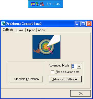
Touchscreen Calibration ................................................. |
87 |
|
Figure F.7:Standard Calibration -1 .............................. |
87 |
|
Figure F.8:Standard Calibration -2 .............................. |
88 |
|
Figure F.9:Standard Calibration -3 .............................. |
88 |
|
Figure F.10:Advanced Calibration -1 ......................... |
89 |
|
Figure F.11:Advanced Calibration -2 .......................... |
90 |
|
Figure F.12:Plot Calibration Data ................................ |
90 |
|
Figure F.13:Draw ........................................................ |
91 |
|
Figure F.14:Clear Screen ............................................. |
92 |
|
Figure F.15:Option ...................................................... |
93 |
Appendix G |
Fuse Specifications ........................................ |
96 |
G.1 |
Fuse Specifications.......................................................... |
96 |
G.2 |
Fuse Replacement ........................................................... |
96 |
|
Figure G.1:Fuse Replacement ...................................... |
96 |
TPC-1261H User Manual |
x |
2
CHAPTER 1
General Information
This chapter gives background information on TPC-1261H..
Sections include:
•Introduction
•Specifications
•I/O Ports Arrangement
•Panel Mounting
•Exploded Diagrams
•Dimensions & Cutout

Chapter 1 General Information
1.1 Introduction
The TPC-1261H touch panel computer is a state-of-the-art HMI (Human Machine Interface). This operator interface with a 12.1” display is an x86-based platform with these key features:
• Fanless
By using a low-power processor, the system does not have to rely on fans, which often are unreliable and causes dust to circulate inside the equipment.
• Bright Display
The TFT LCD display suits industrial demands for clear interfaces.
• Powerful Communication Capability
TPC-1261H provides a powerful I/O interface for easily communicating with other devices. The I/O interface includes serial ports, a parallel port, Ethernet and USB 1.1 support. TPC-1261H also supports the expansion slot PCI/104. This makes it easy to expand with the required PCI/104 modules.
• Windows CE Support
In addition to the OS support of Windows XP, Advantech offers platform support for Windows CE and Windows XP embedded. The optional Windows CE operating system specifically for the TPC1261H is available for Windows CE application program builders.
TPC-1261H User Manual |
2 |

1.2 Specifications
1.2.1 System Kernel
•CPU: GeodeLink Control Processor LX800 500MHz
•BIOS: Award 512KB flash memory
•South Bridge: GeodeLink Control Processor CS5535
•VGA: GeodeLink Control Processor LX800 500MHz
•Ethernet: Realtek RTL8100BL; IEEE 802.3u protocol compatible
•Watchdog Timer: W83627 watchdog timer; 1.6 second timeout period
•IDE: 1 EIDE channel supports one CompactFlash socket onboard (Master) and one IDE interface harddrive (Slave)
1.2.2 I/O Ports
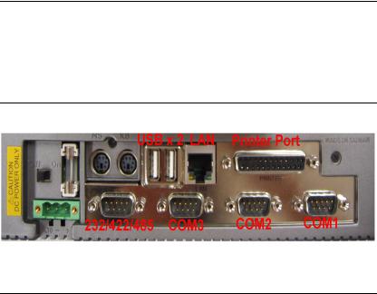
•1 parallel port: supports EPP/ ECP modes
•4 serial ports: RS-232 (COM1, COM2, COM3) and RS-232/422/485 (COM4)
•1 RJ-45 Ethernet port
•1 PS/2 port: 6-pin mini-DIN ports for keyboard and mouse
•2 USB 2.0 Ports: compliant with USB 1.0 and 1.1.
•1 PCI/104 slot
Note: |
COM1 and COM2 only support half-duplex |
|
(Maximum baud rate: 115.2Kbps) |
1.2.3 Safety and Environment
Safety
•FCC Class A
•CE certificated
•The front bezel is compliant with NEMA 4 and IP65
3 |
Chapter1 |

Environment
•Operating Temperature: 0 ~ 50° C (32 ~ 122° F)
•Storage Temperature: -20 ~ 60° C (-4 ~ 140° F)
•Humidity: 40° C @ 10~95% relative humidity (non-condensing)
•Vibration: 1 grms (5~500Hz)
1.3LCD Specifications
•Display Type: TFT color LCD
•Size (diagonal): 12.1”
•Maximum Resolution: 800 x 600 (SVGA)
•Maximum Colors: 256,000
•Pixel Pitch (W x H, mm): 0.3075 x 0.3075
•Viewing Angle: 100°
•Luminance (cd/m² ): 340
•Contrast Ratio: 300
•Operating Temperature: 0 ~ 50° C (32 ~ 122° F) (Ambient)
•Backlight: 2 CCFL
•Backlight Life Time: 50,000 hours
Note |
There might be several bright or dark pixels on |
|
the LCD. This phenomenon is normal in today’s |
|
LCD manufacturing. |
1.4Touchscreen Specifications
•Touch Type: Resistive
•Base Glass Construction: Tempered Glass
•Resolution: 1024 x 1024
•Light Transmission: 75% typical
•Controller: USB Interface
•Lifespan: 1 million touches at single point
TPC-1261H User Manual |
4 |
1.5Power
•Input Voltage: 18 - 32VDC (the fuse will become an open circuit if the input level exceeds 33 VDC)
•Typical: 24VDC@2.5Amp
1.6I/O Ports Arrangement
The arrangement of the I/O ports is shown in Figure 1.1.
Figure 1.1: I/O Port Arrangement
1.7Panel Mounting
1.There is an adhesive waterproof gasket on the Mg-AL front bezel. Make sure the waterproof gasket is in position before installing TPC-1261H into the panel opening.
2.Install the TPC-1261H into the panel opening.
3.Find the eight clampers and eight long screws in the accessory pack. Hook the clampers to the holes around the four sides of the bezel. Insert the screws into every clamper and fasten them. These screws will push the mounting panel and fix the unit.
4.The suggested mounting panel thickness is less than 6 mm (0.236”).
5 |
Chapter1 |
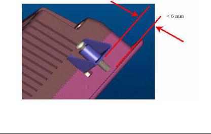
Figure 1.2: Panel Mounting
1.8Dimensions and Cutout
•Weight: 4.1 kg (without HDD)
•Dimensions: 311 x 237 x 58 mm (W x H x D)
•Cutout: 302 x 228 mm (suggested)
TPC-1261H User Manual |
6 |
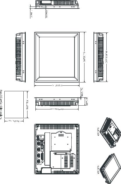
Figure 1.3: Dimensions
7 |
Chapter1 |
TPC-1261H User Manual |
8 |

2
CHAPTER 2
System Setup
This chapter provides a brief explanation for operating TPC-1261H.
Chapter 2 System Setup
You can easily get TPC-1261H started by following the below steps.
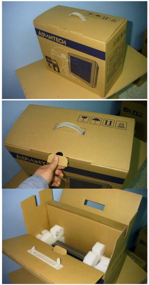
•Step 1: Unpack the TPC-1261H package. Check the packing list at the beginning of this manual to make sure all items have been included.
Figure 2.1: Unpack the Package
TPC-1261H User Manual |
10 |
•Step 2: Install a CompactFlash card containing Windows CE, embedded Windows XP or another operating system.
|
Figure 2.2: Install CompactFlash Memory Card |
Warning |
It is suggested to turn OFF system power as you |
|
plug in or pull out the memory card, even though |
|
the CompactFlash memory is hot swappable. |
• Step 3: Connect the power connector to the 24 VDC power lines. The
power lines can either be of some power adapter or in-house power source.
Figure 2.3: Power Connector and Power Lines
Figure 2.4: Power Receptor & Button Pin Assignment
11 |
Chapter2 |
•Step 4: Plug the power lines into the system power receptor.
•Step 5: Push the power button to power on the system (figure 2.4).
•Step 6: Calibrate the touchscreen (click "PM" in the bottom corner).
Note: |
We are using Windows XP as the example. |
|
Please refer appendix F for detail. |
Figure 2.5: Touchscreen Icon
Figure 2.6: Touchscreen Calibration
TPC-1261H User Manual |
12 |

2
CHAPTER 3
System Engine

Chapter 3 System Engine
Table 3.1: Mainboard Connectors & Jumper Settings
Label |
Function |
Description |
|
|
|
CN2 |
LCD POWER |
LCD INVERTER Connector |
|
|
|
CN3 |
CF |
CompactFlash socket |
|
|
|
CN4 |
IDE |
Internal IDE 44pin(2mm) connector |
|
|
|
CN5 |
ETHERNET |
RJ45 LAN PORT |
|
|
|
CN6 |
LPT |
Printer Port |
|
|
|
CN7 |
COM1 |
Serial port:COM2 RS232 |
|
|
|
CN8 |
COM2 |
Serial port:COM1 RS232 |
|
|
|
CN9 |
DC IN |
DC Power in Connector,HOUSING 5.08 MM 3P |
|
|
|
CN10 |
USB2 |
Two USB Type-A Female to on panel. |
|
|
|
CN11 |
USB1 |
Two USB Type-A Female to on panel. |
|
|
|
CN12 |
PS2/MOUSE |
Standard Mini-DIN 6-pin |
|
|
|
CN13 |
PS2/KEYBOARD |
Standard Mini-DIN 6-pin |
|
|
|
CN14 |
PCI104 |
PCI104 30*4 CONNECTOR |
|
|
|
CN15 |
COM3 |
Serial port:COM1 RS232 |
|
|
|
CN16 |
COM4 |
Serial port:COM1 RS232/485/422 |
|
|
|
JP1 |
PANEL |
PANEL CONNECTOR |
|
|
|
JP2 |
TOUCH |
TOUCH CONNECTOR |
|
|
|
JP4 |
5V/3V |
PCI104 5V/3V SELECT |
|
|
|
J1 |
DDR |
DDR CONNECTOR |
|
|
|
J3 |
1*3 PIN HEADER |
CLEAR CMOS |
|
|
|
SW1 |
POWER SWITCH |
System Power Switch |
|
|
|
BH1 |
BATTERY |
RTC BATTERY |
|
|
|
FS1 |
FUSE |
FUSE HOLDER |
|
|
|
TPC-1261H User Manual |
14 |
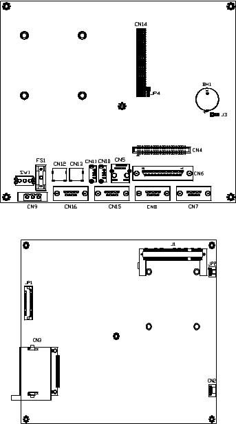
Figure 3.1: Main Board Connectors - 1
Figure 3.2: Main Board Connectors - 2
15 |
Chapter3 |
TPC-1261H User Manual |
16 |

2
CHAPTER 4
Software Configuration
Sections include:
•VGA Driver Installation
•Advantech COM Installation
•Entertainment Encryption/
Decryption Driver Installation
Chapter 4 Software Configuration
A support CD-ROM for TPC-1261H is available and along with the product. There are related utilities and drivers of TPC-1261H for Windows XP. Please insert the support CD-ROM into your CD-ROM
driver and install the VGA graphics driver, Advantech com driver,
Touchscreen driver and WDM driver sequentially. Touchscreen installation is described in the appendix.
4.1 VGA Driver Installation
Please follow the steps to install VGA driver.
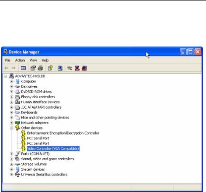
Step 1: Please go to “Device Manager” (control panel -> system -> hardware) and then click “Video Controller”.
Figure 4.1: Device Manager
Step 2: Please go to “Driver” tab to update the driver.
TPC-1261H User Manual |
18 |

Figure 4.2: Update Driver
Step 3: Then follow the update wizard processures.
Figure 4.3: Update Wizard-1
19 |
Chapter4 |
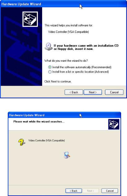
Figure 4.4: Update Wizard-2
Figure 4.5: Update Wizard-3
TPC-1261H User Manual |
20 |
Loading...