


EKI-7758F
8G ports Industrial Managed Redundant Gigabit Ethernet Switch, 4 Gigabit Copper and 4 Gigabit SFP
User Manual
Copyright
The documentation and the software included with this product are copyrighted 2007 by Advantech Co., Ltd. All rights are reserved. Advantech Co., Ltd. reserves the right to make improvements in the products described in this manual at any time without notice. No part of this manual may be reproduced, copied, translated or transmitted in any form or by any means without the prior written permission of Advantech Co., Ltd. Information provided in this manual is intended to be accurate and reliable. However, Advantech Co., Ltd. assumes no responsibility for its use, nor for any infringements of the rights of third parties, which may result from its use.
Acknowledgements
Intel and Pentium are trademarks of Intel Corporation.
Microsoft Windows and MS-DOS are registered trademarks of Microsoft Corp. All other product names or trademarks are properties of their respective owners.
Part No. |
2nd Edition |
Printed in China |
August 2007 |
EKI-7758F User Manual |
ii |
Product Warranty (2 years)
Advantech warrants to you, the original purchaser, that each of its products will be free from defects in materials and workmanship for two years from the date of purchase.
This warranty does not apply to any products which have been repaired or altered by persons other than repair personnel authorized by Advantech, or which have been subject to misuse, abuse, accident or improper installation. Advantech assumes no liability under the terms of this warranty as a consequence of such events.
Because of Advantech′s high quality-control standards and rigorous testing, most of our customers never need to use our repair service. If an Advantech product is defective, it will be repaired or replaced at no charge during the warranty period. For out-of-warranty repairs, you will be billed according to the cost of replacement materials, service time and freight. Please consult your dealer for more details.
If you think you have a defective product, follow these steps:
1.Collect all the information about the problem encountered. (For example, CPU speed, Advantech products used, other hardware and software used, etc.) Note anything abnormal and list any onscreen messages you get when the problem occurs.
2.Call your dealer and describe the problem. Please have your manual, product, and any helpful information readily available.
3.If your product is diagnosed as defective, obtain an RMA (return merchandize authorization) number from your dealer. This allows us to process your return more quickly.
4.Carefully pack the defective product, a fully-completed Repair and Replacement Order Card and a photocopy proof of purchase date (such as your sales receipt) in a shippable container. A product returned without proof of the purchase date is not eligible for warranty service.
5.Write the RMA number visibly on the outside of the package and ship it prepaid to your dealer.
iii
Declaration of Conformity
CE
This product has passed the CE test for environmental specifications. Test conditions for passing included the equipment being operated within an industrial enclosure. In order to protect the product from being damaged by ESD (Electrostatic Discharge) and EMI leakage, we strongly recommend the use of CE-compliant industrial enclosure products.
FCC Class A
This equipment has been tested and found to comply with the limits for a Class A digital device, pursuant to Part 15 of the FCC Rules. These limits are designed to provide reasonable protection against harmful interference when the equipment is operated in a commercial environment. This equipment generates, uses and can radiate radio frequency energy and, if not installed and used in accordance with the instruction manual, may cause harmful interference to radio communications. Operation of this equipment in a residential area is likely to cause harmful interference in which case the user will be required to correct the interference at his own expense.
Technical Support and Assistance
Step |
1. |
Visit the Advantech web site at www.advantech.com/support where you can find |
|
|
the latest information about the product. |
Step |
2. |
Contact your distributor, sales representative, or Advantech’s customer service |
|
|
center for technical support if you need additional assistance. Please have the |
|
|
following information ready before you call: |
-Product name and serial number
-Description of your peripheral attachments
-Description of your software (operating system, version, application software, etc.)
-A complete description of the problem
-The exact wording of any error messages
EKI-7758F User Manual |
iv |
Safety Instructions
1.Read these safety instructions carefully.
2.Keep this User's Manual for later reference.
3.Disconnect this equipment from any AC outlet before cleaning. Use a damp cloth. Do not use liquid or spray detergents for cleaning.
4.For plug-in equipment, the power outlet socket must be located near the equipment and must be easily accessible.
5.Keep this equipment away from humidity.
6.Put this equipment on a reliable surface during installation. Dropping it or letting it fall may cause damage.
7.The openings on the enclosure are for air convection. Protect the equipment from overheating. DO NOT COVER THE OPENINGS.
8.Make sure the voltage of the power source is correct before connecting the equipment to the power outlet.
9.Position the power cord so that people cannot step on it. Do not place anything over the power cord.
10.All cautions and warnings on the equipment should be noted.
11.If the equipment is not used for a long time, disconnect it from the power source to avoid damage by transient over voltage.
12.Never pour any liquid into an opening. This may cause fire or electrical shock.
13.Never open the equipment. For safety reasons, the equipment should be opened only by qualified service personnel.
14.If one of the following situations arises, get the equipment checked by service personnel:
a.The power cord or plug is damaged.
b.Liquid has penetrated into the equipment.
c.The equipment has been exposed to moisture.
d.The equipment does not work well, or you cannot get it to work according to the user's manual.
e.The equipment has been dropped and damaged. f. The equipment has obvious signs of breakage.
15.DO NOT LEAVE THIS EQUIPMENT IN AN ENVIRONMENT WHERE THE STORAGE TEMPERATURE MAY GO BELOW -40 (-40 ) OR ABOVE 85 (185 ). THIS
COULD DAMAGE THE EQUIPMENT. THE EQUIPMENT SHOULD BE IN A CONTROLLED ENVIRONMENT.
v
Safety Precaution - Static Electricity
Follow these simple precautions to protect yourself from harm and the products from damage.
1.To avoid electrical shock, always disconnect the power from your PC chassis before you work on it. Don't touch any components on the CPU card or other cards while the PC is on.
2.Disconnect power before making any configuration changes. The sudden rush of power as you connect a jumper or install a card may damage sensitive electronic components.
EKI-7758F User Manual |
vi |
|
|
Contents |
|
|
Chapter 1 |
Overview |
........................................... |
2 |
|
|
1.1 |
Introduction.......................................... |
2 |
|
|
1.1.1 ...................... |
The SFP Advantage |
2 |
|
|
1.1.2 ........... |
High - Speed Transmissions |
2 |
|
|
1.1.3 ........................... |
Dual Power Input |
2 |
|
|
1.1.4 .......................... |
Flexible Mounting |
2 |
|
|
1.1.5 ..................... |
Advanced Protection |
3 |
|
|
1.1.6 ........ |
Wide Operating Temperature |
3 |
|
|
1.1.7 .................... |
Easy Troubleshooting |
3 |
|
|
1.2 |
Features .............................................. |
4 |
|
|
1.3 |
Specification ........................................ |
5 |
|
|
1.4 |
Packing .........................................List |
7 |
|
|
1.5 |
Safety ................................Precaution |
7 |
|
Chapter 2 |
Installation...................................... |
10 |
||
|
2.1 |
LED ...................................Indicators |
10 |
|
|
Table 2.1: ........................EKI-7758F LED Definition |
10 |
||
|
2.2 |
Dimensions .....................(units: mm) |
11 |
|
|
Figure 2.1: .........................Front View of EKI-7758F |
11 |
||
|
Figure 2.2: ..........................Side View of EKI-7758F |
12 |
||
|
Figure 2.3: ..........................Rear View of EKI-7758F |
13 |
||
|
Figure 2.4: ...........................Top View of EKI-7758F |
14 |
||
|
2.3 |
Mounting............................................ |
15 |
|
|
2.3.1 ............................. |
Wall mounting |
15 |
|
|
Figure 2.5: Combine the Metal Mounting Kit (units: |
|||
|
mm) |
.............................................................................. |
|
15 |
|
2.3.2 ........................ |
DIN - rail Mounting |
16 |
|
|
Figure 2.6: ...................Installation to DIN-rail Step 1 |
16 |
||
|
Figure 2.7: ...................Installation to DIN-rail Step 2 |
17 |
||
|
2.4 |
Network ..........................Connection |
18 |
|
|
2.5 |
Connection to a Fiber Optic Network. 18 |
||
|
Figure 2.8: .................Transceiver to the SFP module |
18 |
||
|
Figure 2.9: ..................................Transceiver Inserted |
19 |
||
|
Figure 2.10: ..............LC connector to the transceiver |
19 |
||
|
Figure 2.11: ............................Remove LC connector |
20 |
||
|
Figure 2.12: ...................Pull out from the transceiver |
20 |
||
|
2.6 |
Power .............................Connection |
21 |
|
Chapter 3 |
Figure 2.8: ..Pin Assignment of the Power Connector |
21 |
||
Configuration ................................. |
24 |
|||
|
3.1 |
RS- ................................232 Console |
24 |
|
|
Figure 3.1: ...............................Open Hyper Terminal |
24 |
||
|
Figure 3.2: ....................COM Port Properties Setting |
25 |
||
|
Figure 3.3: .......Login Screen: RS-232 Configuration |
25 |
||
|
Figure 3.4: ..........................Command Line Interface |
26 |
||
vii |
Contents |
3.1.1 |
Commands Level ........................ |
26 |
Table 3.1: Command Level ......................................... |
26 |
|
3.1.2 |
Commands Set List..................... |
27 |
Table 3.2: Commands Set List .................................... |
27 |
|
3.1.3 |
System Commands Set............... |
27 |
Table 3.3: System Commands Set............................... |
27 |
|
3.1.4 |
Port Commands Set.................... |
28 |
Table 3.4: Port Commands Set ................................... |
28 |
|
3.1.5 |
Trunk Commands Set ................. |
29 |
Table 3.5: Trunk Commands Set................................ |
29 |
|
3.1.6 |
VLAN Commands Set ................. |
30 |
Table 3.6: VLAN Commands Set............................... |
30 |
|
3.1.7 |
Spanning Tree Commands Set ... |
31 |
Table 3.7: Spanning Tree Commands Set .................. |
31 |
|
3.1.8 |
QOS Commands Set................... |
32 |
Table 3.8: QOS Commands Set.................................. |
32 |
|
3.1.9 |
IGMP Commands Set ................. |
32 |
Table 3.9: QOS Commands Set.................................. |
32 |
|
3.1.10 |
Mac/Filter Table Commands Set. 32 |
|
Table 3.10: Mac/Filter Table Commands Set.............. |
33 |
|
3.1.11 |
SNMP Commands Set ................ |
33 |
Table 3.11: SNMP Commands Set.............................. |
33 |
|
3.1.12 |
Port Mirroring Commands Set..... |
34 |
Table 3.12: Port Mirroring Commands Set ................. |
34 |
|
3.1.13 |
802.1x Commands Set................ |
34 |
Table 3.13: 802.1x Commands Set............................. |
34 |
|
3.1.14 |
TFTP Commands Set.................. |
35 |
Table 3.14: TFTP Commands Set .............................. |
35 |
|
3.1.15 |
SystemLog, SMTP and Event ..... |
35 |
Table 3.15: SysLog,SMTP,Event Commands Set...... |
35 |
|
3.1.16 |
SNTP Commands Set................. |
36 |
Table 3.16: SNTP Commands Set............................... |
36 |
|
3.1.17 |
X-ring Commands Set................. |
37 |
Table 3.17: X-ring Commands Set .............................. |
37 |
|
3.2 Web Browser..................................... |
38 |
|
Figure 3.5: Type the address in the URL..................... |
38 |
|
Figure 3.6: Web Login Window.................................. |
38 |
|
Figure 3.7: Main page.................................................. |
39 |
|
3.2.1 |
System ........................................ |
39 |
Figure 3.8: System Information................................... |
40 |
|
Figure 3.9: IP Configuration........................................ |
41 |
|
Figure 3.10: DHCP Server - System Configuration .... |
42 |
|
Figure 3.11: DHCP Server – Client Entries ................ |
42 |
|
Figure 3.12: DHCP Server – Client Entries ................ |
43 |
|
Figure 3.13: TFTP – Update Firmware ....................... |
43 |
|
Figure 3.14: TFTP – Restore Configuration................ |
44 |
|
Figure 3.15: TFTP – Backup Configuration................ |
45 |
|
EKI-7758F User Manual |
viii |
|
Figure 3.16: Syslog Configuration .............................. |
46 |
|
|
Figure 3.17: SMTP Configuration............................... |
47 |
|
|
Figure 3.18: Event Configuration................................ |
48 |
|
|
Figure 3.19: Fault Relay Alarm................................... |
49 |
|
|
Table 3.18: UTC Timezone ......................................... |
49 |
|
|
Figure 3.20: SNTP Configuration ............................... |
51 |
|
|
Figure 3.21: IP Security............................................... |
52 |
|
|
Figure 3.22: User Authentication ................................ |
53 |
|
|
3.2.2 |
Port .............................................. |
54 |
|
Figure 3.23: Port Statistics........................................... |
54 |
|
|
Figure 3.24: Port Control............................................. |
55 |
|
|
Figure 3.25: Aggregator Setting .................................. |
56 |
|
|
Figure 3.26: Aggregator Information .......................... |
56 |
|
|
Figure 3.27: State Activity........................................... |
57 |
|
|
Figure 3.28: Port Mirroring ......................................... |
58 |
|
|
Figure 3.29: Rate Limiting .......................................... |
59 |
|
|
3.2.3 |
Protocol ....................................... |
60 |
|
Figure 3.30: VLAN Configuration .............................. |
60 |
|
|
Figure 3.31: Port based mode ...................................... |
61 |
|
|
Figure 3.32: Port based mode-Add interface............... |
62 |
|
|
Figure 3.33: 802.1Q VLAN Configuration ................. |
63 |
|
|
Figure 3.34: Edit Group Configuration interface ........ |
64 |
|
|
Figure 3.35: Apply Group Configuration interface ..... |
64 |
|
|
Figure 3.36: RSTP System Configuration interface.... |
65 |
|
|
Figure 3.37: RSTP Port Configuration interface ......... |
66 |
|
|
Figure 3.38: SNMP System Configuration interface... |
67 |
|
|
Figure 3.39: Trap Configuration interface................... |
68 |
|
|
Figure 3.40: SNMP V3 Configuration interface ......... |
69 |
|
|
Figure 3.41: QoS Configuration interface ................... |
72 |
|
|
Table 3.19: IGMP types............................................... |
73 |
|
|
Figure 3.42: IGMP Configuration interface ................ |
74 |
|
|
Figure 3.43: X-ring interface ....................................... |
75 |
|
|
3.2.4 |
Security ....................................... |
76 |
|
Figure 3.44: 802.1x/Radius System Configuration |
|
|
|
interface |
....................................................................... |
76 |
|
Figure 3.45: 802.1x/Radius - Port Setting interface .... |
77 |
|
|
Figure 3.46: 802.1x/Radius - Misc Configuration |
|
|
|
interface ....................................................................... |
|
77 |
|
Figure 3.47: .............Static MAC Addresses interface |
78 |
|
|
Figure 3.48: ..........................MAC Filtering interface |
79 |
|
|
Figure 3.49: ....................All MAC Address interface |
79 |
|
|
Figure 3.50: ........................Factory Default interface |
80 |
|
|
Figure 3.51: ..................Save Configuration interface |
80 |
|
Chapter 4 |
Figure 3.52: .........................System Reboot interface |
81 |
|
Troubleshooting ............................ |
84 |
||
Appendix A |
Pin Assignment ...........& Wiring |
86 |
|
|
Figure A.1: ..............................RJ-45 Pin Assignment |
86 |
|
|
Figure A.2: .........................................EIA/TIA-568B |
86 |
|
|
Figure A.3: .........................................EIA/TIA-568A |
86 |
|
ix |
Contents |
Figure A.4: DB 9-pin female connector ...................... |
87 |
||
Appendix B Compatible SFP Modules ........... |
90 |
||
Appendix C X-View |
........................................... |
92 |
|
Figure C.1: X-View interface ...................................... |
92 |
||
Figure ....................C.2: Items to the ‘Task’ menu bar |
92 |
||
Figure ..........C.3: Two devices have been discovered |
93 |
||
Figure ..............C.4: Discovery Filter setting window |
93 |
||
Figure .........................................C.5: Login interface |
94 |
||
Figure ................C.6: User Name/Password interface |
94 |
||
Figure ........................................C.7: Reboot function |
95 |
||
Figure C.8: Press Reboot button to restart the switch .95 |
|||
Figure .......................C.9: Refresh for single function |
96 |
||
Figure .....................C.10: Refresh all the information |
96 |
||
Figure ....................C.11: Log displaying information |
97 |
||
C.1 |
System .............................................. |
98 |
|
C.1.1 ..................... |
System Information |
98 |
|
Figure ................................C.12: System information |
98 |
||
C.1.2 .......................... |
IP Configuration |
98 |
|
Figure ......................C.13: IP Configuration—DHCP |
99 |
||
Figure ...............C.14: IP Configuration—Auto range |
99 |
||
Figure ...................C.15: IP Configuration—Manual |
100 |
||
C.1.3 ............................ |
DHCP Server |
100 |
|
Figure .........................C.16: DHCP Server interface |
101 |
||
Figure ..............C.17: DHCP Server – Client Entries |
101 |
||
Figure ....C.18: DHCP Server – Port and IP Binding |
102 |
||
C.1.4 ...................... |
TFTP Transaction |
102 |
|
Figure ............C.19: TFTP Transaction – Upgrade 1 |
102 |
||
Figure ............C.20: TFTP Transaction – Upgrade 2 |
103 |
||
Figure ...............C.21: TFTP Transaction –Restore 1 |
103 |
||
Figure ..............C.22: TFTP Transaction – Restore 2 |
104 |
||
Figure ..............C.23: TFTP Transaction – Backup 1 |
104 |
||
Figure ..............C.24: TFTP Transaction – Backup 2 |
105 |
||
C.1.5 ..................... |
System Event Log |
105 |
|
Figure ............................C.25: Syslog Configuration |
105 |
||
Figure .........................................C.26: Syslog Table |
106 |
||
Figure ............................C.27: SMTP Configuration |
106 |
||
Figure .............................C.28: Event Configuration |
107 |
||
C.1.6 ............................. |
Time (SNTP) |
107 |
|
Figure .............................C.29: Event Configuration |
108 |
||
C.1.7 ................................. |
IP Security |
108 |
|
Figure ............................................C.30: IP Security |
109 |
||
C.1.8 ................... |
User Authentication |
109 |
|
Figure ..............................C.31: User Authentication |
109 |
||
C.2 |
Port.................................................. |
110 |
|
C.2.1 ............................ |
Port Statistics |
110 |
|
Figure ........................................C.32: Port Statistics |
110 |
||
C.2.2 ............................... |
Port Control |
110 |
|
EKI-7758F User Manual |
x |
Figure C.33: Port Control .......................................... |
111 |
||
C.2.3 |
Port Status ................................ |
111 |
|
Figure C.34: Port Status............................................. |
111 |
||
C.2.4 |
Port Trunk ................................. |
112 |
|
Figure C.35: Port Trunk............................................. |
112 |
||
Figure C.36: Port Trunk Status.................................. |
113 |
||
C.2.5 |
Port Mirroring ............................ |
113 |
|
Figure C.37: Port Mirroring....................................... |
113 |
||
C.2.6 |
Rate Limiting ............................. |
113 |
|
Figure C.38: Rate Limiting........................................ |
114 |
||
C.3 |
Protocol ........................................... |
115 |
|
C.3.1 |
VLAN......................................... |
115 |
|
Figure C.39: VLAN Configuration ........................... |
115 |
||
Figure C.40: 802.1Q VLAN ...................................... |
116 |
||
Figure C.41: Port Configuration................................ |
116 |
||
Figure C.42: VLAN Table......................................... |
117 |
||
Figure C.43: Port-based VLAN................................. |
117 |
||
C.3.2 |
Rapid Spanning Tree ................ |
118 |
|
Figure C.44: RSTP .................................................... |
119 |
||
Figure C.45: RSTP Information ................................ |
119 |
||
C.3.3 |
SNMP........................................ |
119 |
|
Figure C.46: SNMP ................................................... |
120 |
||
Figure C.47: Community Strings............................... |
120 |
||
Figure C.48: Trap Configuration ............................... |
121 |
||
Figure C.49: SNMPv3 Context Table ....................... |
121 |
||
Figure C.50: SNMPv3 User Table ............................ |
122 |
||
Figure C.51: SNMPv3 Group Table.......................... |
122 |
||
Figure C.52: SNMPv3 Access Table......................... |
123 |
||
Figure C.53: SNMPv3 MIBView Table.................... |
124 |
||
C.3.4 |
QoS Configuration..................... |
124 |
|
Figure C.54: QoS....................................................... |
125 |
||
Figure C.55: Port Based Priority ............................... |
125 |
||
Figure C.56: COS Settings ........................................ |
126 |
||
Figure C.57: TOS Settings......................................... |
126 |
||
Table 3.19: IGMP types............................................. |
127 |
||
Figure C.58: IGMP .................................................... |
127 |
||
Figure C.59: IGMP Snooping Table.......................... |
128 |
||
Figure C.60: X-Ring .................................................. |
129 |
||
C.4 |
Security ........................................... |
130 |
|
C.4.1 |
802.1x/RADIUS......................... |
130 |
|
Figure C.61: 802.1x/RADIUS ................................... |
131 |
||
Figure C.62: Port Auth .............................................. |
131 |
||
C.4.2 |
MAC Address Table .................. |
131 |
|
Figure C.63: Static MAC Address............................. |
132 |
||
Figure C.64: MAC Filtering ...................................... |
133 |
||
Figure C.65: All MAC Address................................. |
133 |
||
C.5 |
Factory Default ................................ |
134 |
|
Figure C.66: Factory Default..................................... |
134 |
||
xi |
Contents |
C.6 |
Save To Flash ................................. |
134 |
Figure C.67: Save to Flash ........................................ |
134 |
|
C.7 |
System Reboot................................ |
135 |
Figure C.68: System Reboot...................................... |
135 |
|
EKI-7758F User Manual |
xii |
xiii
Contents

CHAPTER
Overview
Sections include:
z
z
z
z
z
Introduction
Features
Specifications
Packing List
Safety Precaution
1 |
Chapter1 |

Chapter 1 Overview
1.1 Introduction
To create reliability in your network, the EKI-7758F comes equipped with a proprietary redundant network protocol—X-Ring that was developed by Advantech, which provides users with an easy way to establish a redundant Ethernet network with ultra high-speed recovery time less than 10 ms.
Aside from 4 x 10/100/1000Base-T(X) fast Ethernet ports, the EKI-7758F come equipped with 4 SFP (mini-GBIC) fiber optic ports. Traditional RJ-45 ports can be used for uplinking wide-band paths in short distance (< 100 m), while the SFP slots can be used for the application of wideband uploading and long distance transmissions to fit the field request flexibility. Also, the long MTBF (Mean Time Between Failures) ensures that the EKI-7758F will continue to operate until a Gigabit network infrastructure has been established, without requiring any extra upgrade costs.
1.1.1The SFP Advantage
The EKI-7758F’s four SFP fiber slots provide a lot of flexibility when planning and implementing a network. The slots can accept any SFP-type fiber module and these modules are designed for transmitting over distances of either 500m (multi-mode), 10km, 30km, 50km, 70km or 110km (single-mode) – and the slots support SFP modules for WDM single-fiber transmissions. This means that you can easily change the transmission mode and distance of the switch by simply pulling out the SFP module and plugging in a different module. The SFP modules are hot-swappable and plug-and-play! Also, the fact that the switch has four of these slots, means that the network manager can, for example, have one 10km module in one slot and one 110km in the other.
1.1.2High-Speed Transmissions
The EKI-7758F includes a switch controller that can automatically sense transmission speeds (10/100 Mbps). The RJ-45 interface can also be auto-detected, so MDI or MDI- X is automatically selected and a crossover cable is not required. All Ethernet ports have memory buffers that support the store-and-forward mechanism. This assures that data is properly transmitted.
1.1.3Dual Power Input
To reduce the risk of power failure, the EKI-7758C provides +12 ~ 48 VDC dual power inputs. with power reserve protection, which can prevent the switch device broken by wrong power wiring. When one of power input is fail, P-Fail LED will turn on and send an alarm through a relay output for notifying user.
1.1.4Flexible Mounting
EKI-7758F is compact and can be mounted on a DIN-rail or panel, so it is suitable for any space-constrained environment.
EKI-7758F User Manual |
2 |
1.1.5Advanced Protection
The power line of EKI-7758F supports up to 3,000 VDC EFT protection, which secure equipment against unregulated voltage and make systems safer and more reliable. Meanwhile, 4,000 VDC ESD protections for Ethernet ports make EKI-7758F more suitable for harsh environments.
1.1.6Wide Operating Temperature
The operating temperature of the EKI-7758F is between -10 ~ 60 . With such a wide
range, you can use the EKI-7758F in some of the harshest industrial environments that exist.
1.1.7Easy Troubleshooting
LED indicators make troubleshooting quick and easy. Each 10/100/1000 Base-TX port has 2 LEDs that display the link status, transmission speed and collision status. Also the three power indicators P1, P2 and P-Fail help you diagnose immediately.
3 |
Chapter1 |

1.2Features
•All Gigabit Ethernet ports for 4 Copper and 4 SFP
•SFP sockets for easy and flexible fiber expansion
•Redundancy: Gigabit X-Ring (ultra high-speed recovery time < 10ms), RSTP/STP (802.1w/1D)
•Management: Web, Telnet, Serial Console, Windows Utility, SNMP
•Control: VLAN/GVRP, QoS, IGMP Snooping, LACP, Rate Limit
•Security: IP/MAC and port binding, DHCP Server, IP access list, 802.1x, SNMPv3
•Diagnostic: Port statistic, Port Mirroring, RMON, Trap, SMTP Alert, Syslog
•Dual 12 ~ 48 VDC power input and 1 Relay Output
•Robust mechanism and special heat spreader design
EKI-7758F User Manual |
4 |

1.3 Specification
Communications
Standard |
IEEE 802.3, 802.3ab, 802.3ad, 802.3u, 802.3x, |
|
802.3z |
LAN |
IEEE 802.1d, 802.1p, 802.1Q, 802.1w, 802.1X, |
10/100/1000Base-TX, Optional 100Base-FX, |
|
Transmission Distance |
1000Base-SX/LX/LHX/XD/ZX/EZX |
Ethernet: Up to 100m (4-wire Cat.5e, Cat.6 RJ-45 |
|
|
cable suggested for Gigabit port) |
Transmission Speed |
SFP: Up to 110km (depends on SFP) |
Gigabit Copper: 10/100/1000 Mbps, Auto-Negotiation |
|
|
Gigabit Fiber: Up to 1000Mbps |
Interface
Connectors |
4 x RJ-45 (Ethernet) |
|
4 x SFP (mini-GBIC) ports |
LED Indicators |
6-pin removable screw terminal (Power & Relay) |
System: PWR, R.M., PWR1, PWR2, P-Fail |
|
|
Gigabit Copper: Link/Activity, Speed (1000Mbps) |
Console |
SFP: Link/Activity |
RS-232 (RJ-45) |
Network Management
Configuration |
Web browser, Telnet, Serial Console, Windows Utility, |
|
|
TFTP, SNMP v1/v2c/v3, Port Speed/Duplex |
|
|
Configuration |
|
VLAN |
IEEE 802.1Q, GVRP, Port-based, VLAN |
|
Redundancy |
ADVANTECH X-Ring (Recovery time < 10ms at |
|
|
30pcs full loading ring structure), Dual Homing, |
|
|
Couple Ring, 802.1w/D RSTP/STP |
|
Security |
IP Access security, post security, DHCP Server, Port |
|
|
and IP Binding, 802.1X Port Access Control |
|
Traffic Control |
IGMP Snooping/Query for multicast group |
|
|
management Port Trunking, Static/802.3ad LACP |
|
|
Rate limit and storm control |
|
|
IEEE 802.1p QoS Cos/TOS/DSCP priority queuing |
|
|
IEEE 802.3x flow control |
|
Diagnostics |
Port Mirroring, Real-time traffic statistic, MAC Address |
|
|
Table, SNTP, Syslog, E-Mail Alert, SNMP, Trap, |
|
|
RMON |
|
Power |
|
|
|
5 |
Chapter1 |
Power Consumption |
Max. 17 W |
Power Input |
2 x Unregulated +12 ~ 48 VDC |
Fault Output |
1 Relay Output |
Mechanism
Dimensions (WxHxD) |
79 x 152 x 105 mm |
Enclosure |
IP30, metal shell with solid mounting kits |
Mounting |
DIN-rail, wall |
Protection
ESD (Ethernet) |
4,000 VDC |
Surge (EFT for power) |
3,000 VDC |
Power Reverse |
Present |
Overload |
3.2A / 60V Replaceable Fuse |
Environment
Operating Temperature |
-10 |
~ 60 |
(14 ~ 140 ) |
Operating Humidity |
5 ~ 95% |
(non-condensing) |
|
Storage Temperature |
-40 |
~ 85 (-40~185 ) |
|
Storage Humidity |
0 ~ 95% |
(non-condensing) |
|
MTBF |
289,774 hours |
||
Certifications
Safety |
UL, 60950-1, CAN/CSA-C22.2 No.60950 |
EMC |
U.S.A.: FCC Part 15 CISPR 22 |
|
EU: EN55011, EN61000-6-4 |
|
EN55022, Class A, |
|
EN61000-3-2/3 |
|
EN55024 |
|
IEC61000-4-2/3/4/5/6/8/11/12 |
Freefall |
EN61000-6-2 |
IEC60068-2-32 |
|
Shock |
IEC60068-2-27 |
Vibration |
IEC60068-2-6 |
EKI-7758F User Manual |
6 |
1.4Packing List
•1 x EKI-7758F Industrial Managed Gigabit Ethernet Switch
•1 x eAutomation Industrial Communication CD-ROM with software, and User manual
•2 x Wall Mounting Bracket and Screws
•1 x DIN-rail Mounting Bracket and Screws
•1 x 8-pin RJ-45 to RS-232 serial cable
•1 x DC Jack Cable φ2.0/150mm
•1 x EKI-7758F Startup Manual
1.5Safety Precaution
Attention |
IF DC voltage is supplied by an external circuit, please use a protection device |
|
on the power supply input. |
7 |
Chapter1 |
EKI-7758F User Manual |
8 |

CHAPTER
Installation
Sections include:
z
z
z
z
z
z
LED Indicators Dimensions Mounting
Network Connection
Connection to a Fiber Optic Network Power Connection
9 |
Chapter2 |

Chapter 2 Installation
In this chapter, you will be given an overview of the EKI-7758F hardware installation procedures.
2.1 LED Indicators
There are few LEDs display the power status and network status located on the front panel of EKI-7758F, each of them has its own specific meaning shown as below.
Table 2.1: EKI-7758F LED Definition
LED |
Color |
Description |
|
|
PWR |
Green |
On |
|
System power on |
|
|
|
||
Off |
|
No power input |
||
|
|
|
||
|
|
|
|
|
R.M. |
Green |
On |
|
The industrial switch is the master of the X-ring group |
|
|
|
||
Off |
|
The industrial switch is not the master of the X-ring group |
||
|
|
|
||
|
|
|
|
|
PWR1 |
Green |
On |
|
Power input 1 is active |
|
|
|
||
Off |
|
Power input 1 is inactive |
||
|
|
|
||
|
|
|
|
|
PWR2 |
Green |
On |
|
Power input 2 is active |
|
|
|
||
Off |
|
Power input 2 is inactive |
||
|
|
|
||
|
|
|
|
|
|
|
On |
|
Power input 1 or 2 is inactive or port link down |
P-Fail |
Red |
|
(depends on Fault Relay Alarm configuration) |
|
|
|
|||
|
|
|
||
|
|
Off |
|
Power input 1 and 2 are both active, or no power input |
|
|
|
|
|
|
|
On |
|
SFP port is linking |
Link/Active |
|
|
|
|
Green |
Flashing |
|
Data is transmitting or receiving |
|
(G5 ~ G8) |
|
|||
|
|
|
|
|
|
|
Off |
|
Not connected to network |
|
|
|
|
|
|
|
On |
|
Connected to network |
|
Green |
|
|
|
|
Flashing |
|
Networking is active |
|
|
(Upper LED) |
|
||
|
|
|
|
|
G1 ~ G4 |
|
Off |
|
Not connected to network |
|
|
|
|
|
|
Green |
On |
|
The port is operating at speed of 1000M |
|
|
|
|
|
|
(Lower LED) |
Off |
|
The port is disconnected or not operating at speed of 1000M |
|
|
|
||
|
|
|
|
|
EKI-7758F User Manual |
10 |

2.2 Dimensions (units: mm)
Figure 2.1: Front View of EKI-7758F
11 |
Chapter2 |
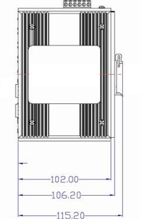
Figure 2.2: Side View of EKI-7758F
EKI-7758F User Manual |
12 |
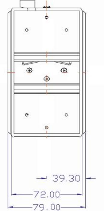
Figure 2.3: Rear View of EKI-7758F
13 |
Chapter2 |
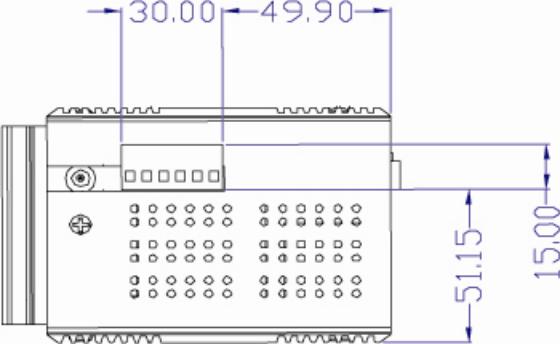
Figure 2.4: Top View of EKI-7758F
EKI-7758F User Manual |
14 |
2.3 Mounting
The EKI-7758F supports two mounting methods: DIN-rail & Wall.
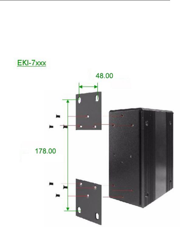
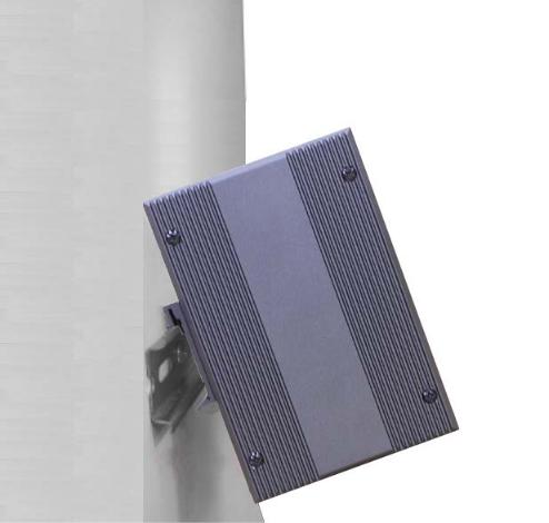
2.3.1Wall mounting
EKI-7758F can be wall-mounted by using the included mounting kit. Then, hang on the EKI-7758F to the nails on the wall.
First, use the screws included in the package to combine the EKI-7758F and metal mounting kit. And then you can install the device firmly via the components, please see Figure 2.5 as below.
Figure 2.5: Combine the Metal Mounting Kit (units: mm)
15 |
Chapter2 |
2.3.2DIN-rail Mounting
You can also mount EKI-7758F on a standard DIN-rail by below steps.
The DIN-rail kit is screwed on the industrial switch when out of factory. If the DIN-rail kit is not screwed on the industrial switch, please screw the DIN-rail kit on the switch first.
First, hang the EKI-7758F to the DIN-rail with angle of inclination. See Figure 2.6.
Figure 2.6: Installation to DIN-rail Step 1
EKI-7758F User Manual |
16 |
 Loading...