


AIMB-210
Table of contents
 Loading...
User Manual
AIMB-210
Intel® Atom™ processor N270
1.6 GHz
FSB 533 MHz Mini-ITX
Motherboard with VGA, LVDS,
TV-Out, 6 COM, Dual GbE,
8 USB, 2 SATA II

Copyright
The documentation and the software included with this product are copyrighted 2009
by Advantech Co., Ltd. All rights are reserved. Advantech Co., Ltd. reserves the right
to make improvements in the products described in this manual at any time without
notice. No part of this manual may be reproduced, copied, translated or transmitted
in any form or by any means without the prior written permission of Advantech Co.,
Ltd. Information provided in this manual is intended to be accurate and reliable. However, Advantech Co., Ltd. assumes no responsibility for its use, nor for any infringements of the rights of third parties, which may result from its use.
Acknowledgements
AWARD is a trademark of Phoenix Technologies Ltd.
IBM and PC are trademarks of International Business Machines Corporation.
®
Intel
Atom™ N270 is trademark of Intel Corporation
WinBond is a trademark of Winbond Corporation.
All other product names or trademarks are properties of their respective owners.
Part No. 2006021001 Edition 2
Printed in Taiwan April 2009
AIMB-210 User Manual ii

A Message to the Customer
Advantech Customer Services
Each and every Advantech product is built to the most exacting specifications to
ensure reliable performance in the harsh and demanding conditions typical of industrial environments. Whether your new Advantech equipment is destined for the laboratory or the factory floor, you can be assured that your product will provide the
reliability and ease of operation for which the name Advantech has come to be
known.
Your satisfaction is our primary concern. Here is a guide to Advantech’s customer
services. To ensure you get the full benefit of our services, please follow the instructions below carefully.
Technical Support
We want you to get the maximum performance from your products. So if you run into
technical difficulties, we are here to help. For the most frequently asked questions,
you can easily find answers in your product documentation. These answers are normally a lot more detailed than the ones we can give over the phone.
So please consult this manual first. If you still cannot find the answer, gather all the
information or questions that apply to your problem, and with the product close at
hand, call your dealer. Our dealers are well trained and ready to give you the support
you need to get the most from your Advantech products. In fact, most problems
reported are minor and are able to be easily solved over the phone.
In addition, free technical support is available from Advantech engineers every business day. We are always ready to give advice on application requirements or specific
information on the installation and operation of any of our products.
iii AIMB-210 User Manual

Declaration of Conformity
FCC
This device complies with the requirements in part 15 of the FCC rules:
Operation is subject to the following two conditions:
! This device may not cause harmful interference
! This device must accept any interference received, including interference that
may cause undesired operation.
This equipment has been tested and found to comply with the limits for a Class A digital device, pursuant to Part 15 of the FCC Rules. These limits are designed to provide reasonable protection against harmful interference when the equipment is
operated in a commercial environment. This equipment generates, uses, and can
radiate radio frequency energy and, if not installed and used in accordance with the
instruction manual, may cause harmful interference to radio communications. Operation of this device in a residential area is likely to cause harmful interference in which
case the user will be required to correct the interference at his/her own expense. The
user is advised that any equipment changes or modifications not expressly approved
by the party responsible for compliance would void the compliance to FCC regulations and therefore, the user's authority to operate the equipment.
Caution! There is a danger of a new battery exploding if it is incorrectly installed.
Do not attempt to recharge, force open, or heat the battery. Replace the
battery only with the same or equivalent type recommended by the manufacturer. Discard used batteries according to the manufacturer's
instructions.
AIMB-210 User Manual iv

Memory Compatibility
Brand Size Speed Vendor PN Advantech PN Memory
DDR2
667
DDR2
667
DDR2
667
DDR2
667
DDR2
667
DDR2
667
DDR2
667
DDR2
667
DDR2
667
DDR2
667
DDR2
800
TS32MSQ64V NA
TS6QSJ23002-6S
TS128MSQ64V6J NA
TS5QSU21640-6S
76.9325G.B17
76.0325G.B18 96SD2I-1G667-AP
NA NA
NA NA
NA NA
NA NA
TS2QSU23003-5E
Transcend
(RoHS)
Apacer
(RoHS)
DSL
(RoHS)
Transcend
(RoHS)
256 MB
512 MB
1 GB
2 GB
512 MB
1 GB
256 MB
512 MB
1 GB
2 GB
1 GB
Hynix HY5PS121621B
FP-Y5 (32x16)
96SD2-512M667NNTR
96SD2-2G667NNTR1
96SD2I-512M667-APELPIDA E5108AG-6E-
96SD2-1G800NNTR
SAMSUNG
K4T51083QC ZCE6
(64x8)
SAMSUNG
K4T51083QC ZCE6
(64x8)
Micron D9HNL (128x8)
E (64x8)
ELPIDA E5108AGBG-
6E-E (64x8)
ELPIDA E5116AF-6E-
E (32x16)
ELPIDA E5108AGBG-
6E-E (64x8)
ELPIDA E5108AGBG-
6E-E (64x8)
ELPIDA E1108ACSE-
6E-E (128x8)
HYNIX
HY5PS12821E-FP-S5
(64x8)
DSL
(RoHS)
Transcend
Apacer
1 GB
2 GB
256 MB
512 MB
2 GB
256 MB
512MB
1GB
DDR2
800
DDR2
800
DDR2
533
DDR2
533
DDR2
533
DDR2
533
DDR2
533
DDR2
533
NA NA
NA NA
TS32MSQ64V NA
TS64MSQ64V5J
TS5QSU21640-6S
78.82054.420 NA
76.8325G.116
78.02G71.422
96SD2-512M533NNTR
96SD2-2G667NNTR1
96SD2-512M533NNAP
96SD2-1G533NN-APELPIDA TWN
ELPIDA TWN
E5108AHSE-8E-E
(64x8)
ELPIDA JPN
E1108ACSE-8E-E
(128x8)
Hynix HY5PS121621B
FP-Y5 (32x16)
Infineon HYB18T512
800AF37 SVV39006
0526 (32x8)
Micron D9HNL (128x8)
ELPIDA JAPAN
E5116AB-E
05050WPWA (64x8)
ELPIDA JAPAN
E5108AB-E
04520WR5Q (64x8)
E5108AE-E (64x8)
v AIMB-210 User Manual

Ordering Information
AIMB-210 Ordering Information
Part Number
AIMB-210G2-S6A1E
AIMB-210F-S6A1E*
* Minimum order quantity is required
On-board
Processor
ATOM N270
1.6 GHz
ATOM N270
1.6 GHz
Chipset Memory LAN COM DVI LVDS TPM
945GSE
945GSE
Product Warranty (2 years)
Advantech warrants to you, the original purchaser, that each of its products will be
free from defects in materials and workmanship for two years from the date of purchase.
This warranty does not apply to any products which have been repaired or altered by
persons other than repair personnel authorized by Advantech, or which have been
subject to misuse, abuse, accident or improper installation. Advantech assumes no
liability under the terms of this warranty as a consequence of such events.
Because of Advantech’s high quality-control standards and rigorous testing, most of
our customers never need to use our repair service. If an Advantech product is defective, it will be repaired or replaced at no charge during the warranty period. For outof-warranty repairs, you will be billed according to the cost of replacement materials,
service time and freight. Please consult your dealer for more details.
If you think you have a defective product, follow these steps:
1. Collect all the information about the problem encountered. (For example, CPU
speed, Advantech products used, other hardware and software used, etc.) Note
anything abnormal and list any onscreen messages you get when the problem
occurs.
2. Call your dealer and describe the problem. Please have your manual, product,
and any helpful information readily available.
3. If your product is diagnosed as defective, obtain an RMA (return merchandise
authorization) number from your dealer. This allows us to process your return
more quickly.
4. Carefully pack the defective product, a fully-completed Repair and Replacement
Order Card and a photocopy proof of purchase date (such as your sales receipt)
in a shippable container. A product returned without proof of the purchase date
is not eligible for warranty service.
5. Write the RMA number visibly on the outside of the package and ship it prepaid
to your dealer.
DDR2
533
DDR2
533
2 6 None Single None
2 6 None Dual Yes
AIMB-210 User Manual vi

Initial Inspection
Before you begin installing your motherboard, please make sure that the following
materials have been shipped:
! 1 x AIMB-210 ATOM N270 1.6 GHz Mini-ITX with VGA/LVDS/Dual GbE LAN
! 1 x IDE HDD cable
! 2 x SATA HDD cable
! 2 x SATA Power cable
! 3 x Serial port cable
! 1 x I/O port bracket
! 1 x Startup manual
! 1 x Driver CD
! 1 x Warranty card
If any of these items are missing or damaged, contact your distributor or sales representative immediately. We have carefully inspected the AIMB-210 mechanically and
electrically before shipment. It should be free of marks and scratches and in perfect
working order upon receipt. As you unpack the AIMB-210, check it for signs of shipping damage. (For example, damaged box, scratches, dents, etc.) If it is damaged or
it fails to meet the specifications, notify our service department or your local sales
representative immediately. Also notify the carrier. Retain the shipping carton and
packing material for inspection by the carrier. After inspection, we will make arrangements to repair or replace the unit.
vii AIMB-210 User Manual

AIMB-210 User Manual viii

Contents
Chapter 1 General Information ............................1
1.1 Introduction ............................................................................................... 2
1.2 Features .................................................................................................... 2
1.3 Specifications ............................................................................................ 3
1.3.1 System .......................................................................................... 3
1.3.2 Memory......................................................................................... 3
1.3.3 Input/Output .................................................................................. 3
1.3.4 Graphics........................................................................................ 3
1.3.5 Ethernet LAN ................................................................................ 3
1.3.6 Industrial features ......................................................................... 4
1.3.7 Mechanical and environmental specifications............................... 4
1.4 Jumpers and Connectors .......................................................................... 4
Table 1.1: Jumpers...................................................................... 4
Table 1.2: Connectors ................................................................. 4
1.5 Board layout: Jumper and Connector Locations ....................................... 6
Figure 1.1 Jumper and Connector Location ................................ 6
Figure 1.2 I/O Connectors ........................................................... 6
1.6 AIMB-210 Board Diagram ......................................................................... 7
Figure 1.3 AIMB-210 Board Diagram .......................................... 7
1.7 Safety Precautions .................................................................................... 8
1.8 Jumper Settings ........................................................................................ 9
1.8.1 How to Set Jumpers...................................................................... 9
1.8.2 CMOS Clear (CMOS1) ................................................................. 9
Table 1.3: CMOS1....................................................................... 9
1.8.3 COM2 RS 232/422/485 Mode Selector (JSETCOM2)................ 10
Table 1.4: COM2 RS 232/422/485 Mode Selector
(JSETCOM2) ............................................................ 10
1.8.4 JLV1/JLV2: LCD Power 3.3 V/5 V Selector ................................ 10
Table 1.5: JLV1/JLV2: LCD Power 3.3 V/5 V Selector.............. 10
1.8.5 JPSON1: ATX, AT Mode Selector .............................................. 11
Table 1.6: JPSON1: ATX, AT Mode Selector............................ 11
1.8.6 JWDT1: Watchdog Timer Output Option .................................... 11
Table 1.7: JWDT1: Watchdog Timer Output Option.................. 11
1.9 System Memory ...................................................................................... 12
1.10 Memory Installation Procedures.............................................................. 12
Chapter 2 Connecting Peripherals ....................13
2.1 Introduction ............................................................................................. 14
2.2 Parallel Port (LPT1)................................................................................. 14
2.3 Primary (IDE1) IDE Connector................................................................ 15
2.4 USB Ports (LAN1_USB12/LAN2_USB34/USB56/USB78) ..................... 16
Table 2.1: LAN LED Indicator.................................................... 16
2.5 TV-Out Connector (TVOUT1) ................................................................. 17
Table 2.2: TV-Out Connector (TVOUT1)................................... 17
2.6 VGA Connector (VGA1) .......................................................................... 18
2.7 Serial Ports (COM1~COM6) ................................................................... 19
2.8 PS/2 Keyboard and Mouse Connector (KBMS1) .................................... 20
2.9 CPU Fan Connector (CPU_FAN1).......................................................... 21
2.10 System FAN Connector (CHA_FAN1) .................................................... 22
2.11 Front Panel Connectors (JFP1/JFP2/JFP3)............................................ 23
2.11.1 ATX soft power switch (JFP1 / PWR_SW) ................................ 23
2.11.2 Reset (JFP1 / RESET)................................................................ 23
2.11.3 HDD LED (JFP2 / HDDLED)....................................................... 23
ix AIMB-210 User Manual

2.11.4 External speaker (JFP2 / SPEAKER)......................................... 23
2.11.5 Power LED and keyboard lock connector
(JFP3 / PWR_LED & KEY LOCK) .............................................. 24
Table 2.3: ATX power supply LED status
(No support for AT power)........................................ 24
2.12 Line In, Line Out, Mic In Connector (AUDIO1)........................................ 25
2.13 Serial ATA Interface (SATA1, SATA2).................................................... 26
2.14 PCI .......................................................................................................... 27
2.15 Front Headphone Connector (FPAUD1)................................................. 28
2.16 ATX Power Connector (EATXPWR1) ..................................................... 29
2.17 SPI Flash connector(SPI_CN1) .............................................................. 30
2.18 LCD Inverter Connector INV1 & INV2 (Optional).................................... 31
2.19 LVDS Connector LVDS1 & LVDS2 (Optional) ........................................ 32
2.20 Digital I/O Connector (DIO1)................................................................... 33
Chapter 3 BIOS Operation ................................. 35
3.1 Introduction ............................................................................................. 36
3.2 BIOS Setup ............................................................................................. 36
3.2.1 Main Menu.................................................................................. 37
3.2.2 Standard CMOS Features .......................................................... 38
3.2.3 Advanced BIOS Features........................................................... 39
3.2.4 Advanced Chipset Features ....................................................... 40
3.2.5 Integrated Peripherals ................................................................ 42
3.2.6 USB Device Setting .................................................................... 44
3.2.7 Security Chip Configuration (Optional Item) ............................... 45
3.2.8 TPM Support............................................................................... 45
3.2.9 Power Management Setup ......................................................... 46
3.2.10 PnP/PCI Configurations.............................................................. 48
3.2.11 PC Health Status ........................................................................ 49
3.2.12 Frequency/Voltage Control......................................................... 49
3.2.13 Load Setup Defaults ................................................................... 50
3.2.14 Set Password.............................................................................. 50
3.2.15 Save & Exit Setup....................................................................... 52
3.2.16 Quit without Saving..................................................................... 52
Chapter 4 Chipset Software Installation Utility 53
4.1 Before You Begin.................................................................................... 54
4.2 Introduction ............................................................................................. 54
4.3 Windows XP Driver Setup....................................................................... 55
Chapter 5 VGA Setup ......................................... 57
5.1 Introduction ............................................................................................. 58
5.2 Windows Vista/XP/2000.......................................................................... 58
Chapter 6 LAN Configuration ............................ 59
6.1 Introduction ............................................................................................. 60
6.2 Features.................................................................................................. 60
6.3 Installation............................................................................................... 60
6.4 Win XP/Vista Driver Setup (Realtek RTL8111C) .................................... 60
AIMB-210 User Manual x

Appendix A Programming the Watchdog Timer..61
A.1 Programming the Watchdog Timer ......................................................... 62
A.1.1 Watchdog Timer Overview.......................................................... 62
A.1.2 Programming the Watchdog Timer ............................................. 62
Table A.1: Watchdog Timer Registers ....................................... 64
A.1.3 Example Program ....................................................................... 65
Appendix B I/O Pin Assignments..........................69
B.1 Parallel Port (LPT1)................................................................................. 70
Table B.1: Parallel Port (LPT1) .................................................. 70
B.2 USB Header (USB56, USB78)................................................................ 70
Table B.2: USB Header (USB56)............................................... 70
B.3 VGA Connector (VGA1) .......................................................................... 71
Table B.3: VGA Connector (VGA1) ........................................... 71
B.4 RS-232 Interface ..................................................................................... 71
Table B.4: RS-232 Interface (COM1~COM4) ............................ 71
B.5 RS-232/422/485 Setting Interface (JETCOM2)....................................... 72
Table B.5: RS-232/422/485 Setting Interface (JETCOM2) ........ 72
B.6 SPI_CN1: SPI Fresh Card Pin Connector............................................... 72
Table B.6: SPI_CN1:SPI Fresh Card Pin Connector................. 72
B.7 PS/2 Keyboard and Mouse Connector (KBMS1) .................................... 73
Table B.7: PS/2 Keyboard and Mouse Connector (KBMS1) .....73
B.8 CPU Fan Power Connector (CPU_FAN1) .............................................. 73
Table B.8: CPU Fan Power Connector (CPU_FAN1)................ 73
B.9 System Fan Power Connector (CHA_FAN1) .......................................... 74
Table B.9: System Fan Power Connector
(SYSFAN1/SYSFAN2) ............................................. 74
B.10 Power LED & Keyboard Lock Connector (JFP3) .................................... 74
Table B.10:Power LED & Keyboard Lock Connector (JFP3)...... 74
B.11 HDD LED and External Speaker Connector (JFP2/HDD LED and
SPEAKER) .............................................................................................. 75
Table B.11:External Speaker Connector (JFP2/SPEAKER)....... 75
B.12 ATX Soft Power Switch and Reset Connector
(JFP1/ PWR-SW and RESET) ................................................................ 75
Table B.12:Reset Connector (JFP1/ RESET)............................. 75
B.13 ATX Power Connector (EATXPWR1) ..................................................... 76
Table B.13:ATX Power Connector (ATX2) ................................. 76
B.14 USB/LAN ports (LAN1_USB12/LAN2_USB34)....................................... 76
Table B.14:USB Port................................................................... 76
Table B.15:Ethernet 10/100 Mbps RJ-45 Port ............................ 76
B.15 Line In, Line Out, Mic In Connector (AUDIO1)........................................ 77
B.16 Serial ATA0/1 (SATA1/SATA2)............................................................... 77
Table B.16:Serial ATA 0/1 (SATA1/SATA2) ............................... 77
B.17 AT/ATX Mode (PSON1) .......................................................................... 77
Table B.17:AT/ATX Mode (PSON1) ........................................... 77
B.18 AC-97 Audio Interface (FPAUD1) ........................................................... 77
Table B.18:AT/ATX Mode (PSON1) ........................................... 77
B.19 GPIO Pin Header (GPIO1)...................................................................... 78
Table B.19:AT/ATX Mode (PSON1) ........................................... 78
B.20 LVDS Connector: LVDS1 & LVDS2 (Optional) ....................................... 79
Table B.20:LVDS1 Connector (Optional).................................... 79
Table B.21:LVDS2 Connector (Optional).................................... 80
B.21 LVDS Power Jumper (JLV1, JLV2)......................................................... 80
Table B.22:LVDS Power Jumper ................................................ 80
B.22 LVDS Invert: INV1 & INV2 (Optional)...................................................... 81
Table B.23:LVDS Power Jumper ................................................ 81
B.23 System I/O Ports ..................................................................................... 81
xi AIMB-210 User Manual

Table B.24:System I/O Ports ...................................................... 81
B.24 DMA Channel Assignments .................................................................... 82
Table B.25:DMA Channel Assignments ..................................... 82
B.25 Interrupt Assignments ............................................................................. 82
Table B.26:Interrupt Assignments .............................................. 82
B.26 1st MB Memory Map............................................................................... 82
Table B.27:1st MB Memory Map ................................................ 82
AIMB-210 User Manual xii

Chapter 1
1 General Information

1.1 Introduction
The AIMB-210 is designed with the Intel® 945GSE and the ICH7M for industrial applications that require both performance computing and enhanced power management
capabilities. The motherboard has on board CPU Intel
533 MHz front side bus and DDR2 533 MHz up to 2 GB.
®
Atom™ N270 1.6GHz with
The AIMB-210 offers cost-saving integrated graphics, built on the Intel
chipset and features the unique Intel
VGA performance and shares system memory up to 224 MB.
Advantech AIMB-210 is designed with an Intel
®
ATOM™ N270 1.6GHz FSB 533 MHz processor. A rich I/O connectivity of 6
Intel
serial ports, 8 USB 2.0, Dual GbE LAN and 2 SATA ports.
1.2 Features
! Cost effective 945GSE chipset: supports 533 Front side bus
! Rich I/O connectivity: 6 serial ports, 8 USB 2.0, Dual GbE LAN
! Standard Mini-ITX form factor with industrial feature: The AIMB-210 is a full-
featured Mini-ITX motherboard with balanced expandability and performance
! Wide selection of storage devices: IDE HDD, SATA HDD, CF, customers ben-
efit from the flexibility of using the most suitable storage device for larger capacity
! Optimized integrated graphic solution: With Intel
tor 950, supports versatile display options and 32-bit 3D graphics engine.
®
945GSE
®
Extreme Graphics architecture that maximizes
®
945GSE chipset and on board CPU
®
Graphics Media Accelera-
AIMB-210 User Manual 2

1.3 Specifications
1.3.1 System
! CPU: Intel® Atom™ N270 1.6 GHz FSB 533 MHz
! BIOS: Award SPI 16 Mbit BIOS
! System chipset: Intel
! SATA hard disk drive interface: Two on-board SATA connectors with data
transmission rate up to 150 MB
! IDE Interface: One onboard IDE connector supporting up to two enhanced IDE
devices. Supports PIO mode 4 (16.67 MB/s data transfer rate) and ATA 33/66/
100 (33/66/100 MB/s data transfer rate) BIOS enabled/disabled
! CF interface: Supports compact flash Type II
1.3.2 Memory
! RAM: Up to 2 GB in 1 slots 200-pin SODIMM sockets. Supports single channel
DDRII 533 SDRAM
1.3.3 Input/Output
! PCI bus: 1 PCI slot
! Enhanced parallel port: Configured to LPT1, with 25 pin box header. Supports
EPP/SPP/ECP
! Serial ports: Six serial ports, COM2 is RS-232/422/485 and five of RS-232
serial ports
! Keyboard and PS/2 mouse connector: Two 6-pin mini-DIN connectors are
located on the mounting bracket for easy connection to a PS/2 keyboard and
mouse
! USB port: Supports up to eight USB 2.0 ports with transmission rate up to 480
Mbps, 4 on board pin header and 4 external ports)
! GPIO connector: 16-bit general purpose Input/Output
®
945GSE with ICH7M
Chapter 1 General Information
1.3.4 Graphics
! Controller: Chipset integrated VGA controller
! Display memory: Dynamically shared system memory up to 224 MB
! CRT: Up to 2048 x 1536 resolution, 400 MHz RAMDAC
! LVDS1: Supports single channel 18-bit/ dual channel 36-bit LVDS
! LVDS2 (optional): Supports single channel 18/24-bit/ dual channel 24/48-bit
LVDS via Chrontel 7308B transmitter
! TV-Out: Support both S-video and composite video via cables (TV-out function
is not supported during POST stage)
1.3.5 Ethernet LAN
! Supporting dual 10/100/1000 Mbps Ethernet port (s) via PCI Express x1 bus
which provides 500 MB/s data transmission rate
! Controller: LAN: Realtek RTL8111C
3 AIMB-210 User Manual

1.3.6 Industrial features
! Watchdog timer: Can generate a system reset. The watchdog timer is pro-
grammable, with each unit equal to one second or one minute (255 levels)
! TPM1.2(optional): Infineon TPM chip SLB9635 TT 1.2 Module Onboard
1.3.7 Mechanical and environmental specifications
! Operating temperature: 0 ~ 60° C (32 ~ 140° F, Depending on CPU)
! Storage temperature: -20 ~ 70° C (-4 ~ 158° F)
! Humidity: 5 ~ 95% non-condensing
! Power supply voltage: +3 .3 V, + 5 V, +1 2 V, -1 2 V, 5 V sb
! Power consumption:
+5 V @ 1.96 A, +3.3 V @ 1.21 A, +12 V @ 0.19 A, 5 VSB @ 0.28, -12 V@ 0.06
A. Measure the maximum current value which system under maximum load
(CPU: Top speed, RAM & Graphic: Full loading)
! Board size: 170 mm x 170 mm (6.69" x 6.69")
! Board weight: 0.365 kg
1.4 Jumpers and Connectors
Connectors on the AIMB-210 motherboard link it to external devices such as hard
disk drives and a keyboard. In addition, the board has a number of jumpers used to
configure your system for your application.
The tables below list the function of each of the board jumpers and connectors. Later
sections in this chapter give instructions on setting jumpers. Chapter 2 gives instructions for connecting external devices to your motherboard.
Table 1.1: Jumpers
Label Function
CMOS1 CMOS clear
JPSON1 AT/ATX mode selector
JSETCOM2 Serial port: RS232/RS422/RS485
Table 1.2: Connectors
Label Functions
JFP1 Power Switch / Reset connector
JFP2 External speaker / SATA HDD LED connector / SM Bus connector
Power LED
JFP3(Keyboard Lock
and Power LED)
CMOS1 CMOS clear (Default 1-2)
JSETCOM2 COM2 RS232/422/485 Jumper Setting
JLV1 LVDS1 LCD power 3.3V/5V selection Default (1-2, 3.3V)
JLV2 LVDS2 LCD power 3.3V/5V selection Default (1-2, 3.3V)
JPSON1 AT(1-2) / ATX(2-3) (Default 2-3)
LPT1 parallel connector
Suspend: Fast flash (ATX/ AT)
System On: ON (ATX/ AT)
System Off: OFF (AT)
System Off: Slow flash (ATX)
AIMB-210 User Manual 4

USB56 USB port 5, 6 (on board)
USB78 USB port 7, 8 (on board)
VGA1 VGA connector
VGA2 TV-Out connector
COM12 Serial port: COM1 (RS232) and COM2 (RS232, RS422 and RS485)
COM3 Serial port: COM3 (RS232)
COM4 Serial port connector
COM5 Serial port connector
COM6 Serial port connector
KBMS1 PS/2 Keyboard and Mouse connector
CPUFAN1 CPU FAN connector(3-pin)
SYSFAN1 System FAN connector(3-pin)
LAN1_USB12 LAN1 / USB port 1, 2
LAN2_USB34 LAN2 / USB port 3, 4
CF1 CF Socket
AUDIO1 Audio connector
FPAUD1 HD Audio Front Panel Pin Header
GPIO1 GPIO Header
IDE1 IDE connector
EATXPWR1 ATX 20Pin Main power connector
INV1 LVDS1 Inverter Power
INV2 LVDS2 Inverter Power
LVDS1 LVDS1 connector (Internal)
LVDS2 LVDS2 connector (Internal)
PCI1 PCI Slot
SATA1 Serial ATA1
SATA2 Serial ATA2
DIMMA1 Memory connector channel
BAT1 Battery Connector
SPI_CN1 SPI flash update connector
JWDT1 Watchdog Reset
SPI1 SPI BIOS socket
Chapter 1 General Information
5 AIMB-210 User Manual
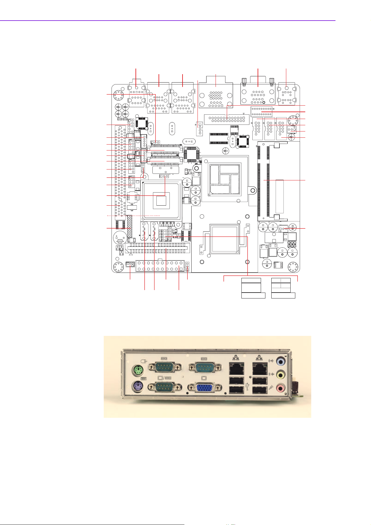
1.5 Board layout: Jumper and Connector Locations
FPAUD1
KBMS1COM12
COM4
LPT1
JSETCOM2
COM5
COM6
TVOUT1
LAN2
USB34
LAN1
USB12
VGA1
COM3
Audio1
DIMM A1
CPUFAN1
JWDT1
SYSFAN1
SATA1 SATA2
JPSON1
CMOS1
PCI1
CF
EATXPWR1
JFP1
JFP2
JFP3
PWR-SW RESET
HDD LED
S P E A K E R
PWR_LED & KEY LOCK
IDE1
INV2
USB78
USB56
JLV1
LVDS2
JLV2
LVDS1
INV1
DIO1
SPI_CN1
qwer
qwert
qetu
wryi
Figure 1.1 Jumper and Connector Location
Figure 1.2 I/O Connectors
AIMB-210 User Manual 6
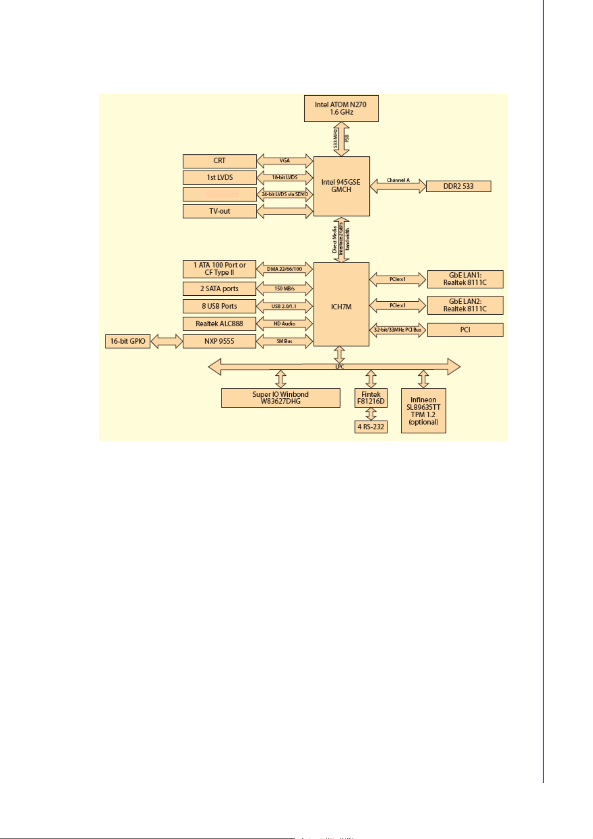
1.6 AIMB-210 Board Diagram
2nd LVDS (Optional)
Chapter 1 General Information
Figure 1.3 AIMB-210 Board Diagram
7 AIMB-210 User Manual
1.7 Safety Precautions
Warning! Always completely disconnect the power cord from chassis whenever
you work with the hardware. Do not make connections while the power
is on. Sensitive electronic components can be damaged by sudden
power surges. Only experienced electronics personnel should open the
PC chassis.
Caution! Always ground yourself to remove any static charge before touching the
motherboard. Modern electronic devices are very sensitive to electrostatic discharges. As a safety precaution, use a grounding wrist strap at
all times. Place all electronic components on a static-dissipative surface
or in a static-shielded bag when they are not in the chassis.
Caution! The computer is provided with a battery-powered real-time clock circuit.
There is a danger of explosion if battery is incorrectly replaced. Replace
only with same or equivalent type recommended by the manufacturer.
Discard used batteries according to manufacturer's instructions.
Caution! There is a danger of a new battery exploding if it is incorrectly installed.
Do not attempt to recharge, force open, or heat the battery. Replace the
battery only with the same or equivalent type recommended by the manufacturer. Discard used batteries according to the manufacturer’s
instructions.
AIMB-210 User Manual 8

1.8 Jumper Settings
This section provides instructions on how to configure your motherboard by setting
the jumpers. It also includes the motherboards's default settings and your options for
each jumper.
1.8.1 How to Set Jumpers
You can configure your motherboard to match the needs of your application by setting the jumpers. A jumper is a metal bridge that closes an electrical circuit. It consists
of two metal pins and a small metal clip (often protected by a plastic cover) that slides
over the pins to connect them. To “close” (or turn ON) a jumper, you connect the pins
with the clip. To “open” (or turn OFF) a jumper, you remove the clip. Sometimes a
jumper consists of a set of three pins, labeled 1, 2, and 3. In this case you connect
either pins 1 and 2, or 2 and 3. A pair of needle-nose pliers may be useful when setting jumpers.
1.8.2 CMOS Clear (CMOS1)
The AIMB-210 motherboard contains a jumper that can erase CMOS data and reset
the system BIOS information. Normally this jumper should be set with pins 1-2
closed. If you want to reset the CMOS data, set J1 to 2-3 closed for just a few seconds, and then move the jumper back to 1-2 closed. This procedure will reset the
CMOS to its default setting.
Chapter 1 General Information
Table 1.3: CMOS1
Function Jumper Setting
*Keep CMOS data
Clear CMOS data
* Default
1-2 closed
2-3 closed
9 AIMB-210 User Manual
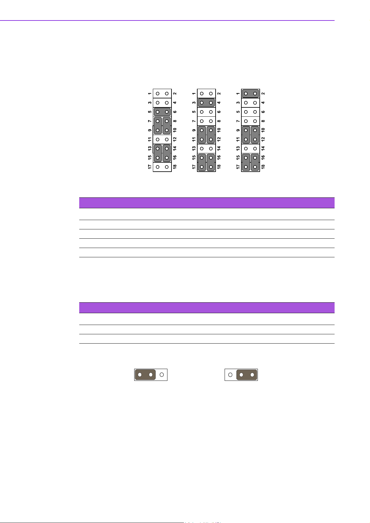
1.8.3 COM2 RS 232/422/485 Mode Selector (JSETCOM2)
Users can use JSETCOM2 to select among RS 232/422/485 modes for COM2. The
default setting is RS 232.
RS232* RS422 RS485
Table 1.4: COM2 RS 232/422/485 Mode Selector (JSETCOM2)
Function Jumper Setting
*RS232 (5-6) + (7-9) + (8-10) + (13-15) + (14-16) closed
RS422 (3-4) + (9-11) + (10-12) + (15-17) + (16-18) closed
RS-485 (1-2) + (9-11) + (10-12) + (15-17) + (16-18) closed
*: Default
1.8.4 JLV1/JLV2: LCD Power 3.3 V/5 V Selector
Table 1.5: JLV1/JLV2: LCD Power 3.3 V/5 V Selector
Closed Pins Result
1-2* 3.3 V*
2-3 5 V
*Default
1 1
3.3 V
1-2 closed
5 V
2-3 closed
AIMB-210 User Manual 10
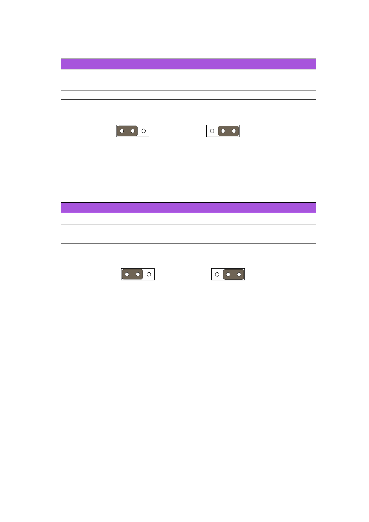
1.8.5 JPSON1: ATX, AT Mode Selector
Table 1.6: JPSON1: ATX, AT Mode Selector
Closed Pins Result
1-2 AT Mode
2-3* ATX Mode
*Default
1 1
Chapter 1 General Information
AT Mode
1-2 closed
ATX Mode
2-3 closed
1.8.6 JWDT1: Watchdog Timer Output Option
Table 1.7: JWDT1: Watchdog Timer Output Option
Closed Pins Result
1-2 NC
2-3* System Reset*
*Default
1 1
NC
1-2 closed
System Reset
2-3 closed
11 AIMB-210 User Manual

1.9 System Memory
The AIMB-210 has one socket for a 200-pin SODIMMx1.
All these sockets use 1.8 V unbuffered double data rate synchronous DRAMs (DDR
SDRAM). They are available in capacities of 256, 512, and 1024 MB. The sockets
can be filled in any combination with DIMMs of any size, giving a total memory size
between 256 MB and 2 GB. AIMB-210 does NOT support ECC (error checking and
correction).
1.10 Memory Installation Procedures
To install SODIMMs, first make sure the two handles of the SODIMM socket are in
the “open” position, i.e., the handles lean outward. Slowly slide the SODIMM module
along the plastic guides on both ends of the socket. Then press the SODIMM module
well down into the socket, until you hear a click when the two handles have automatically locked the memory module into the correct position of the SODIMM socket. To
remove the memory module, just push both handles outward, and the memory module will be ejected by the mechanism.
AIMB-210 User Manual 12

Chapter 2
2 Connecting
Peripherals
2.1 Introduction
You can access most of the connectors from the top of the board as it is being
installed in the chassis. If you have a number of cards installed or have a packed
chassis, you may need to partially remove the card to make all the connections.
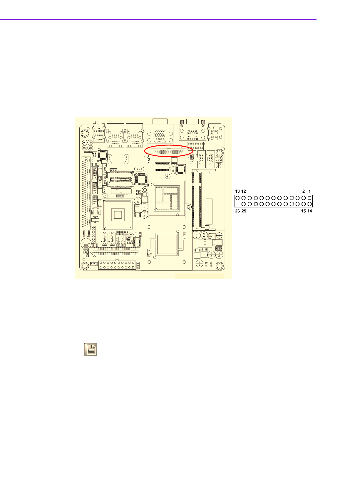
2.2 Parallel Port (LPT1)
The parallel port is normally used to connect the motherboard to a printer. The AIMB210 includes an onboard parallel port, accessed through a 25-pin flat-cable connector, LPT1.
Note! Parallel cable is not enclosed in the box as a standard accessory. The
order part number is 1700008809.
AIMB-210 User Manual 14
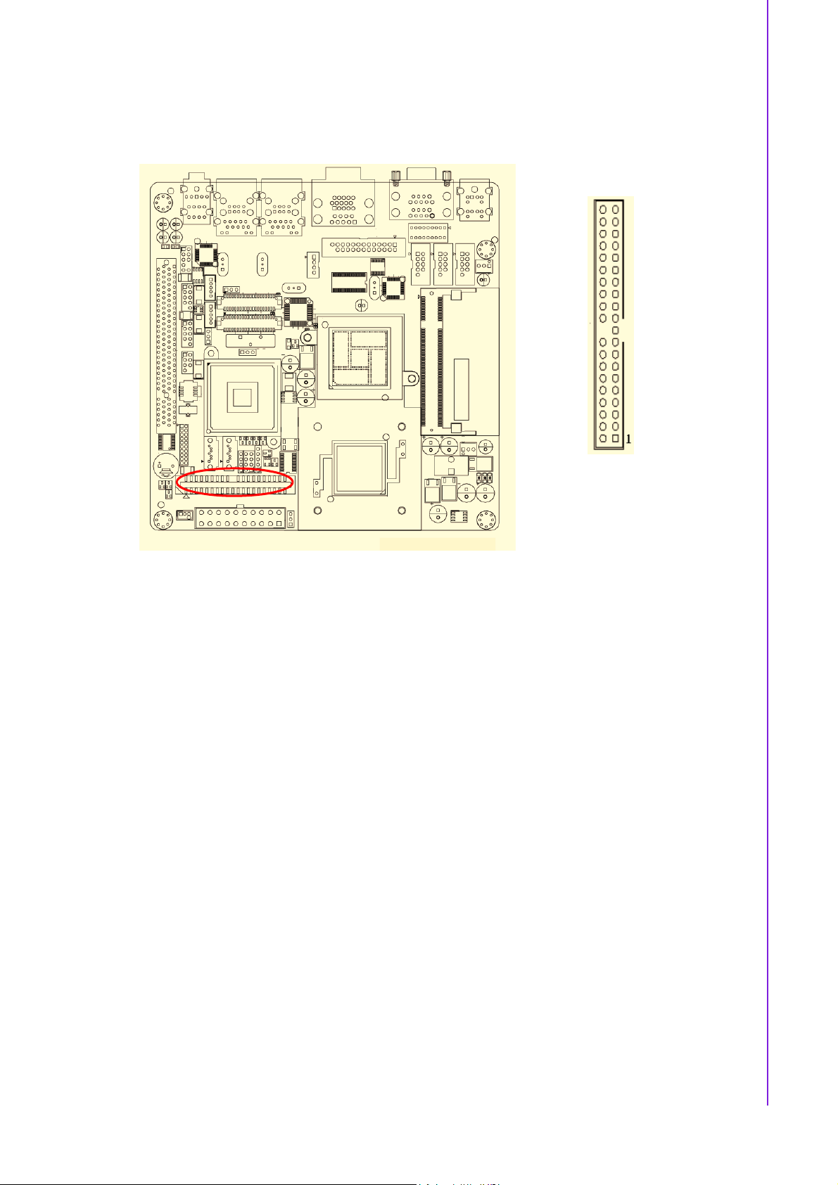
2.3 Primary (IDE1) IDE Connector
Chapter 2 Connecting Peripherals
15 AIMB-210 User Manual
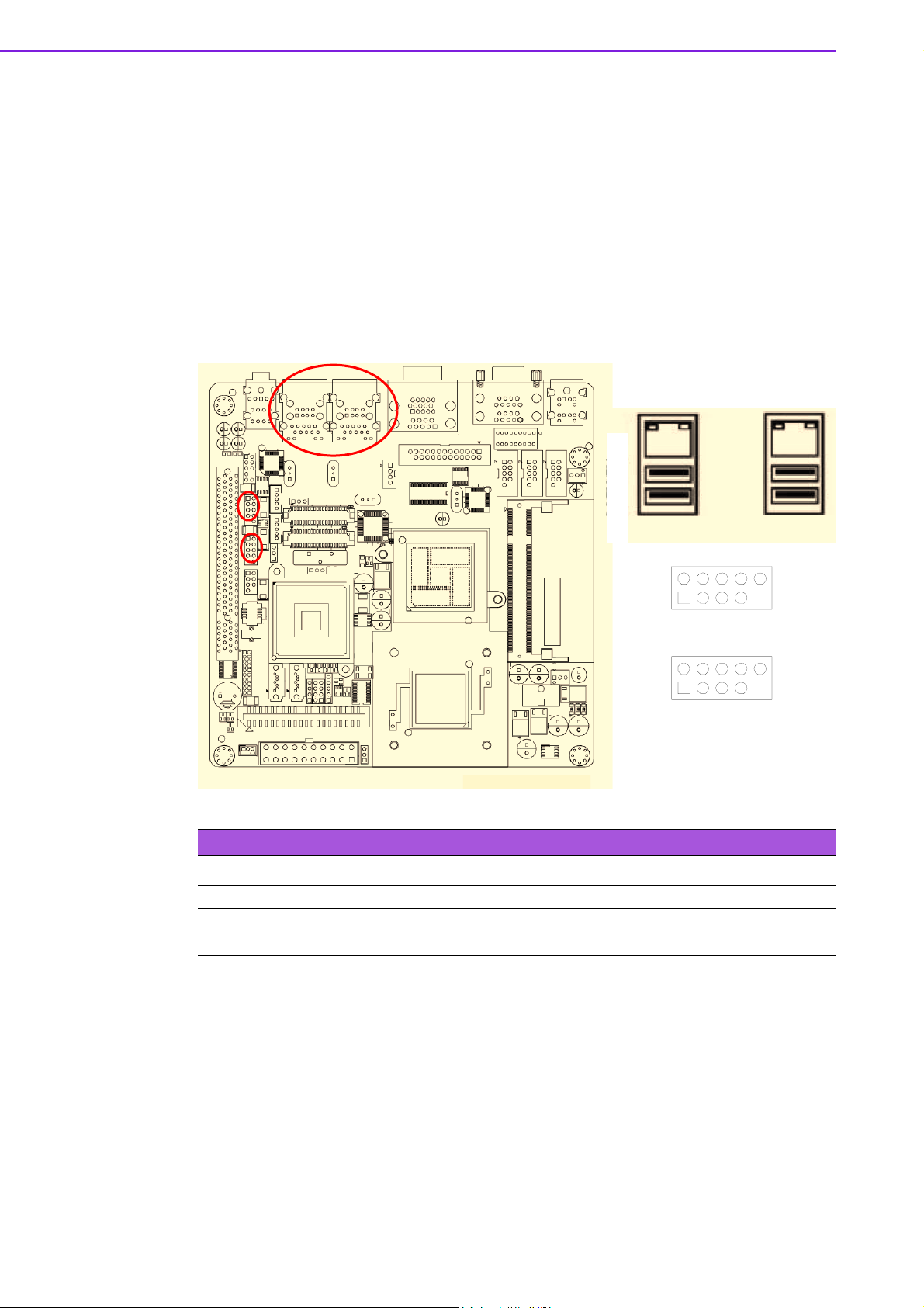
2.4 USB Ports (LAN1_USB12/LAN2_USB34/USB56/
USB78)
The AIMB-210 provides up to eight ports of USB (Universal Serial Bus). The USB
interface complies with USB Specification Rev. 2.0 supporting transmission rate up to
480 Mbps and is fuse protected. The USB interface can be disabled in the system
BIOS setup.
The AIMB-210 is equipped with one high-performance 1000 Mbps Ethernet LANs.
They are supported by all major network operating systems. The RJ-45 jacks on the
rear plate provide convenient or 1000 Mbps operation.
LAN2_USB34 LAN1_USB12
LAN1_USB12 LAN2_USB34
Table 2.1: LAN LED Indicator
LAN Mode Lan Indicator
1 Gbps Link on LED1 Green on
100 Mbps Link on LED1 Orange on
Active LED2 Green flash
USB56
USB78
AIMB-210 User Manual 16
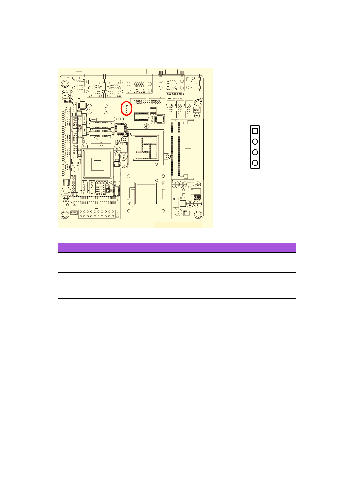
2.5 TV-Out Connector (TVOUT1)
Chapter 2 Connecting Peripherals
1
2
3
4
Table 2.2: TV-Out Connector (TVOUT1)
Pin Signal
1 TV_Pb
2TV_Y
3 TV_Pr
4GND
17 AIMB-210 User Manual
Loading...