


INTRAC-305 |
PREFACE |
INTRAC™-305
INTELLIGENT TRACKING ANTENNA CONTROL UNIT
INSTALLATION & USER MANUAL
ISSUE 3.2
10 June 2008
Advantech AMT Ltd
39 Edison Road
St Ives
Huntingdon
Cambs PE27 3LF
England
Tel |
UK General Enquiries |
|
01480 357600 |
|
International General Enquiries |
+ 44 1480 357600 |
|
Fax |
UK 01480 357601 |
International + 44 1480 357601 |
|
info.europe@advantechwireless.com |
|
||
Website |
http://www.advantechwireless.com |
|
|
The copyright of this document is vested in Advantech AMT Ltd and the document is issued in confidence for the purpose only for which it is supplied. It must not be reproduced, in whole or in part, or used for tendering or manufacturing purposes or disclosed to a third party except with the written consent of Advantech AMT Ltd. Advantech AMT is a wholly owned operating company of Advantech Wireless Inc.
© 2011 Advantech Wireless. |
INTRAC-305 MANUAL - ISSUE 3.2 |
Page i |

PREFACE |
INTRAC-305 |
PREFACE |
|
|
This equipment manual provides user/operational and |
|
installation information on the Advantech AMT Limited |
|
INTRAC-305 Satellite Tracking Antenna Controller. |
MANUAL SECTIONS :- |
|
Introducing the INTRAC-305 |
An overview of the INTRAC-305. |
Safety |
Safe usage of the INTRAC-305. |
Specification & Options |
The supplied specification, the fitted options and the available |
|
options. |
Operating the INTRAC-305 |
How to use and operate the INTRAC-305. |
Alarms |
A description of the alarm conditions which can occur. |
Technical Description |
A technical description of the operation of the INTRAC-305. |
Installation |
How to install and set-up an INTRAC-305 system, includes |
|
information on the external connections to the INTRAC-305. |
Fault Finding |
Assistance in finding any faults which may arise. |
Warranty and Repair |
Warranty and repair service provided by Advantech AMT |
Information |
Ltd. |
Page ii |
INTRAC-305 MANUAL - ISSUE 3.2 |
© 2011 Advantech Wireless |

INTRAC-305 |
PREFACE |
© 2011 Advantech Wireless. |
INTRAC-305 MANUAL - ISSUE 3.2 |
Page iii |

CONTENTS |
INTRAC-305 |
SUBJECT |
PAGE |
Preface ................................................................................................................... |
i |
Contents .................................................................................................................. |
ii |
Introducing the INTRAC-305 .................................................................................... |
iv |
Quick Start Guide ……………………......................................................................... vii |
|
1. SAFETY ................................................................................................................. |
1 |
Electrical ................................................................................................. |
1 |
Fusing ...................................................................................... |
1 |
Earthing .................................................................................... |
1 |
Battery Disposal ....................................................................... |
1 |
RF I/P Connector Voltage ......................................................... |
1 |
Emergency Stop ....................................................................... |
1 |
Mechanical .............................................................................................. |
2 |
EMC ........................................................................................................ |
2 |
2. SPECIFICATIONS & OPTIONS ............................................................................ |
3 |
Requirements of Antenna System .......................................................... |
3 |
Specification ........................................................................................... |
4 |
Options ................................................................................................... |
6 |
3. OPERATING THE INTRAC-305 ............................................................................ |
9 |
Front Panel ............................................................................................. |
9 |
The Menu Structure ............................................................................... |
10 |
The Menu Screen ................................................................................... |
11 |
Alphabetical Index of the Menus ............................................................ |
12 |
The Menus ............................................................................................. |
14 |
Normal Operation ................................................................................... |
50 |
4. ALARMS & ERRORS ............................................................................................ |
51 |
Primary Alarms ...................................................................................... |
51 |
Secondary Alarms .................................................................................. |
52 |
Alarm Outputs ........................................................................................ |
52 |
Recovering from Alarms ........................................................................ |
52 |
Power Failure ......................................................................................... |
53 |
Errors ..................................................................................................... |
53 |
IESS-412 Data ....................................................................................... |
53 |
5. TECHNICAL DESCRIPTION ................................................................................. |
55 |
The Tracking Algorithm ......................................................................... |
55 |
The Modes ............................................................................................. |
58 |
Standby ................................................................................... |
58 |
Auto .......................................................................................... |
58 |
Manual ..................................................................................... |
59 |
Goto ......................................................................................... |
59 |
Remote .................................................................................... |
61 |
Using IESS-412 or NORAD Data .......................................................... |
61 |
The IESS-412 Data ................................................................. |
61 |
NORAD Data ............................................................................ |
63 |
Rapid Model Generation ........................................................................ |
63 |
Program Track ....................................................................................... |
64 |
Reserve Model ........................................................................................ |
64 |
Clear Models ........................................................................................... |
64 |
Antenna Motion Limits ............................................................................ |
65 |
Axes Position .......................................................................................... |
65 |
Tracking Signal ....................................................................................... |
65 |
Page iv |
INTRAC-305 MANUAL - ISSUE 3.2 |
© 2011 Advantech Wireless |

INTRAC-305 |
CONTENTS |
SUBJECT |
|
|
PAGE |
6. INSTALLATION ....................................................................................... |
|
..........….. |
67 |
Introduction ..........................................................................................…. |
67 |
||
Connections (general) ............................................................................ |
|
68 |
|
Rear Panel Layout |
.................................................................................. |
|
69 |
Connector Pin Allocations :- |
|
|
|
Resolvers |
...................................................................………….. |
70 |
|
Motor Control ............................................................................ |
|
71 |
|
Stp-Trk / Alarms ......................................................................... |
|
72 |
|
Communication Ports ................................................................. |
|
72 |
|
|
Remote Port …………………………………………… 72 |
||
|
Test Ports ………………………………………………. |
73 |
|
|
Serial Port RS422/423 Setting .............................…. 74 |
||
|
Serial Port Usage .................................................…. 74 |
||
Tracking Signal Connections ...................... |
............................…. |
75 |
|
Resolvers (pointing angles) ....................................................................... |
|
75 |
|
Southern Hemisphere ............................................................................… |
76 |
||
Tracking Signal Input ...........................................................................…. |
76 |
||
With IBR-L |
.............................................................................…. |
76 |
|
Without IBR-L .................................................. |
......................…. |
76 |
|
Operational Checks ..............................................................................…. |
77 |
||
7. FAULT FINDING .................................................................................................... |
|
|
79 |
Introduction ............................................................................................ |
|
|
79 |
Fault Symptoms :- |
|
|
|
INTRAC doesn’t appear to power up ....................................... |
|
80 |
|
Replacing display back-light ..................................................... |
|
80 |
|
Front panel keys do not function .............................................. |
|
82 |
|
Emergency Stop does not function .......................................... |
|
82 |
|
Pointing angles incorrect ......................................................... |
|
82 |
|
No antenna drive ...................................................................... |
|
83 |
|
No tracking signal ..................................................................... |
|
84 |
|
8. WARRANTY & REPAIR ........................................................................................ |
|
|
85 |
Warranty ................................................................................................. |
|
|
85 |
Repair Service ....................................................................................... |
|
|
85 |
Repairs not under Warranty ................................................................... |
|
86 |
|
APPENDICES ........................ |
See separate appendices index |
............................. |
87 |
© 2011 Advantech Wireless. |
INTRAC-305 MANUAL - ISSUE 3.2 |
Page v |

INTRODUCTION |
INTRAC-305 |
INTRODUCING THE INTRAC-305
The INTRAC-305 INtelligent TRacking Antenna Controller is a microprocessor based controller for tracking any nominally geostationary satellite including those at low elevation or with high angles of inclination. It has been designed as a direct physical replacement for the Andrew APC300 Steptrack Controller. For information on replacing an Andrew APC300 with the INTRAC-305 see section 6 - Installation.
The INTRAC-305 builds a model of the satellite’s orbit using a mathematical algorithm. To build the orbit model the INTRAC makes measurements by perturbing the antenna pointing angle very slightly and monitoring the change in received beacon signal strength. These small movements enable the INTRAC to estimate the position of the satellite and this estimate is used by the modelling algorithm.
The system always tracks the satellite from the orbit model. The small movements of antenna pointing are only used to maintain and update the model.
By using the model to point the antenna the INTRAC system ensures that the antenna is always pointed accurately at the satellite. This is in contrast to Step Track systems where the antenna spends most of the time not actually pointing directly at the satellite.
The regular measurements made by the INTRAC ensure that changes in the apparent orbit, due to station keeping manoeuvres or other causes, are identified. The model is modified and refined to incorporate these changes and accurate tracking is automatically maintained. The INTRAC will automatically increase the measuring rate if necessary in order to obtain sufficient information on the changing orbit.
As the INTRAC tracks using its orbit model it will continue to track the satellite if the tracking signal is degraded or lost. The satellite position may be accurately predicted from the model for up to 72hrs without a tracking signal.
The INTRAC system provides this exceptional tracking performance and robustness for satellites with any inclination, at any look angle, even in the presence of severe beacon signal degradation entirely automatically. No operator intervention or parameter setting is required when conditions or satellites are changed.
Page vi |
INTRAC-305 MANUAL - ISSUE 3.2 |
© 2011 Advantech Wireless |
INTRAC-305 |
INTRODUCTION |
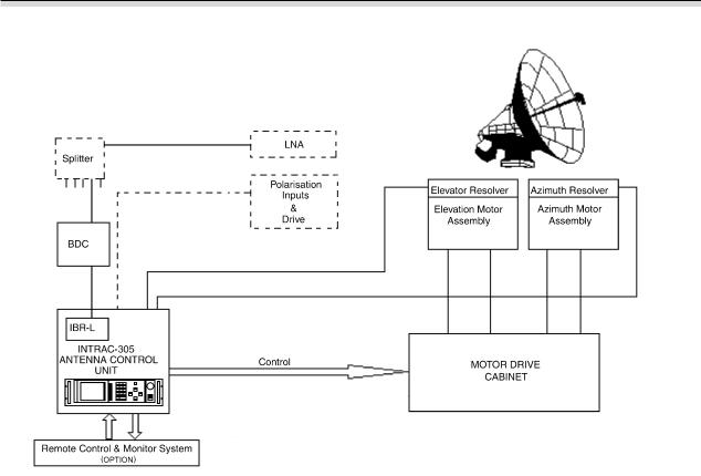
A Typical System
|
The antenna position resolvers provide direction information |
|
to the INTRAC. The IBR-L (beacon receiver) provides |
|
tracking signal strength. (A signal strength derived dc voltage |
|
from an external receiver may be used in place of the |
|
Advantech AMT IBR-L) |
|
The Motor Drive Cabinet receives the antenna drive |
|
commands from the INTRAC and drives the azimuth, |
|
elevation and polarisation (option) motors and brake |
|
assemblies. |
|
Limit switches on the antenna prevent it from being moved |
|
beyond mechanically defined positions. |
|
The INTRAC-305 may be controlled from its front panel or |
|
from an optional PC based Remote Control and Monitoring |
|
Terminal. |
Retro Fitting |
Existing Step Track or Program Track installations may be |
|
updated to INTRAC systems. Advantech AMT Ltd. have |
|
considerable experience of retro fitting INTRAC systems. |
© 2011 Advantech Wireless. |
INTRAC-305 MANUAL - ISSUE 3.2 |
Page vii |

IQUICK START GUIDE |
INTRAC-305 |
A suggested quick start procedure is given below:
1/ Before modifying system make a note the antenna pointing angles from the old tracking system.
2/ Perform any recommended resolver mounting bracket modifications.
3/ Connect INTRAC-305 in place of Andrew APC300 and check that the Fitted Options (Home>Function>System Setup>Fitted Options) (Manual page 39) are set correctly. Note that the resolvers used with the APC300 system were normally x2 resolvers which would require the x2 setting in the fitted options.
4/ Select Station Coordinates (Home>Function>System Setup>Station Coordinates) and ensure that latitude is in correct hemisphere (North or South). You only need to enter the correct station co-ordinates if you intend to use IESS-412 or Norad ephemeris data.
5/ Select Date and Time (Home>Function>System Setup>Date & Time) and enter the correct time and date (in UT (GMT)). This is only strictly necessary if you intend to use IESS-412 or Norad ephemeris data, but most users prefer to set the time correctly anyway.
6/ Select beamwidth (Home>Function>System Setup>Az & El Beamwidth) and set the receive 3 dB beamwidths of your antenna.
7/ Now ensure drive direction feedback is correct.
Select Manual on INTRAC . (Home>New Mode>Manual/Stow) Note displayed Az angle. Command drive Right. Check if displayed angle increases or decreases.
Command drive left. Check if displayed angle increase or decreases.
Continue driving left until displayed angle has returned to the previously noted angle.
The angle should have increased while driving right and decreased while driving left. If it did the opposite then the resolver sense is not correct and will need correcting. By bringing the antenna back to the original displayed angle we have maintained the angle reference.
Note the displayed Elevation angle and repeat the operation for Elevation. Commanding Up should give an increasing angle, Down a decreasing angle. If you found the opposite then you will need to change the elevation resolver sense. Make sure you return the antenna to the same elevation position (reading).
8/ If either resolver senses required changing then Select Fine Tune (Home>Function>System Setup>Fine Tune) and change the required senses on the first screen. Then press EN to continue and adjust the fine tune offsets so that the angle display reads the correct angles ( the ones you noted in step 1).
9/ Now check that Manual drive drives the angles in the expected direction. At this point you can also check that the physical direction on motion of the antenna is also correct, but this will be correct if the original installation was correct.
10/ Connect the beacon signal.
If an IBR-L is fitted and an L-band beacon is available connect this to the RF input on the rear panel of the INTRAC. Select the correct frequency and check that a valid beacon level is displayed. Manually peak the antenna to maximize the beacon level and check that the beacon does not overload (24.9 dB displayed).
Page viii |
INTRAC-305 MANUAL - ISSUE 3.2 |
© 2011 Advantech Wireless |

INTRAC-305 |
QUICK START GUIDE |
If an IBR-L is not fitted then provide a voltage signal to the beacon 1 input. You will need to adjust the potentiometers (See manual page 76) to set the gain and offset to the correct values. Manually peak the antenna to maximize the beacon level and check that the beacon does not overload (24.9 dB displayed).
11/ Set any other parameters, such as Soft Limits.
12/ Select Auto-New Model (Home>New Mode>Auto New Model) and press enter. Monitor system over 24 hours and check that system is maintaining track with displayed mode
“Learning”. Soon after the 24 hour learning period the mode should change to “Tracking”, indicating that the system has successfully computed a full INTRAC model.
© 2011 Advantech Wireless. |
INTRAC-305 MANUAL - ISSUE 3.2 |
Page ix |

SAFETY |
INTRAC-305 |
1.SAFETY
WARNING
POSSIBLE LETHAL POTENTIALS EXIST WITHIN THIS EQUIPMENT
THE COVERS SHOULD NOT BE REMOVED EXCEPT BY QUALIFIED PERSONNEL. SWITCH OFF POWER AND ISOLATE SUPPLY BEFORE REMOVING COVERS.
IF IT IS NECESSARY TO OPERATE THE EQUIPMENT WITH THE COVERS REMOVED FOR SERVICING PURPOSES ALL NECESSARY PRECAUTIONS SHOULD BE TAKEN TO PROTECT AGAINST ELECTRIC SHOCKS
ELECTRICAL
Fusing The standard unit is protected by a user replacable fuse in the live/phase power supply line.
Care should be taken to ensure that the power cable is correctly connected to the power source such that the live/phase connection of the INTRAC is connected to the live/phase terminal of the supply.
When replacing the fuse be sure to do so with one of the correct value and type.
The Dual Redundant power supply version is protected by separate board mounted fuses on each power supply. These are not user replaceable.
Earthing It is important that the electrical supply has a good and proper earth and that earth is connected through to the INTRAC-305 via the power cable.
Battery Disposal The processor board contains a Nickel Cadmium (NiCd) or Lithium battery. These elements are toxic. The battery should be disposed of according to national requirements. DO NOT PLACE IN NORMAL GARBAGE OR IN A FIRE.
RF I/P Connector for IBR-L 18Vdc may be present on the inner of the N-Type connector to power the LNB/BDC. This voltage can be removed by unplugging connector J41.
Emergency Stop There is a latching emergency stop switch on the INTRAC front panel. Pressing this switch will remove power from the antenna drive motors and the INTRAC will enter Standby mode. To restore drive the switch should be rotated clockwise (CW) and Auto Continue selected.
Page 10 |
INTRAC-305 MANUAL - Issue 3.2 |
© Advantech AMT Ltd |
1
INTRAC-305 |
SAFETY |
Facilities exist at the Motor Drive Cabinet for the connection of external emergency stop switches. It is highly recommended that those fitted be of the latching type.
MECHANICAL
Mounting The INTRAC-305 must not be mounted so that it is supported only by the front panel. A proper rack mounting kit must be used. This may be either of the fixed mounting type or the sliding rail type.
EMC
The unit is designed to meet the requirements of the EC EMC Directive and conforms to the relevant standards for EMC emissions and immunity.
Important To ensure that an INTRAC installation also complies with the EMC Directive it is important to make all interconnections between the INTRAC-305 and associated equipment using good quality screened cables as recommended in the appropriate sections of this manual.
© 2011 Advantech Wireless |
INTRAC-305 MANUAL - Issue 3.2 |
Page 11 |

2
INTRAC-305 |
SPECIFICATION & OPTIONS |
2.SPECIFICATION & OPTIONS
The following pages contain the specification of the INTRAC305, a list and description of the available options and a chart of the delivered configuration.
Required Mechanical Characteristics of the Antenna System
To enable the full tracking performance of the INTRAC-305 the antenna system must conform to certain overrun and tracking constraints.
The tracking drive speed must be less than 1/10 of the antenna beamwidth per second and the overrun (drift) when power is removed from the motors must be less than 1/20 of the beamwidth.
If the system does not conform to these requirements please consult with Advantech AMT Limited.
© 2011 Advantech Wireless. |
INTRAC-305 MANUAL - Issue 3.2 |
Page 1 |

SPECIFICATION & OPTIONS |
INTRAC-305 |
SPECIFICATION |
|
Tracking Accuracy |
Typically <0.1dB RMS signal degradation after tracking for |
|
30minutes (with tracking signal). |
Prediction Accuracy |
Typically <0.1dB RMS signal degradation over 72hrs (after |
|
loss of tracking signal). |
Tracking Signal |
May be derived from an external tracking receiver or from the |
|
(optional) Integral Beacon Receiver (IBR-L). |
External |
DC voltage varying directly with received signal strength |
|
(in dB). Scale factors between 0.1V/dB and 1.0V/dB can be |
|
preset with up to 10V offset. |
Internal |
Internal IBR-L requires an L-band signal with a level in the |
|
range -80dBm to -45dBm and C/No >40dB. Stability better |
|
than 150KHz. The received frequency is selected from the |
|
INTRAC front panel. |
|
The signal voltage and lock lost indicators are generated |
|
internally. |
Antenna Position Encoders |
Single resolver units. Operating frequency is 800Hz nominal. |
Az & El |
The INTRAC-305 is designed to operate directly with |
|
standard Andrew resolvers. Antennas used with the APC300 |
|
controller, for which the INTRAC-305 is a replacement, are |
|
normally fitted with x2 resolvers. The part numbers of the two |
|
(alternative manufacturers) 2x resolvers known to have been |
|
used by Andrew are: |
|
Harowe 11BRCX-310-M-85V |
|
Clifton 11-BHM-19F/F776 |
|
The INTRAC-305 can be configured (by the user in “Fitted |
|
Options”) to operate with the lower resolution (x1) resolver |
|
that may be fitted to antennas intended for APC100 control. |
|
The part numbers of the two (alternative manufacturers) 1x |
|
resolvers known to have been used by Andrew are: |
|
Harrowe 11_BRCX-310-R-85V |
|
Clifton 11-BHW-46TK/F561 or F817 |
Pol |
The standard version of the INTRAC-305 is firmware |
|
configured for x1 resolvers. Firmware to enable the use of a |
|
x2 resolver for can be provided on request. |
Page 2 |
INTRAC-305 MANUAL - Issue 3.2 |
©2011 Advantech Wireless |

2
INTRAC-305 |
SPECIFICATION & OPTIONS |
Position Offset |
The indicated pointing angles can be electrically offset in all |
|
axes to an accuracy of 0.01 to compensate for angular |
|
mounting offset in the position encoders. |
Back-up |
Time is maintained by a battery backed clock. Operating |
|
parameters, data and orbital models are held in EEPROM. |
Outputs |
Antenna drive. |
|
|
Emergency Stop contacts. |
|
|
Alarm contacts. |
|
Dimensions |
483mm Wide x 132mm High x 406mm Deep. |
|
|
(19” rack x 3U). |
|
Mounting |
Standard 19” rack mounts or rails. |
|
|
DO NOT MOUNT BY FRONT PANEL LUGS ALONE |
|
|
THE UNIT MUST BE SUPPORTED ALONG ITS SIDES. |
|
Weight |
12kg |
(without IRB-L). |
|
15kg |
(with IRB-L). |
Operating Temperature |
0 C - 40 C. |
|
Relative Humidity |
10% - 90% non-condensing. |
|
Power |
220V - 240V 50Hz 50W. |
|
|
110V - 120V 60Hz 50W. |
|
|
Power supplies are auto-switching |
|
Country of Origin |
United Kingdom. |
|
© 2011 Advantech Wireless. |
INTRAC-305 MANUAL - Issue 3.2 |
Page 3 |

SPECIFICATION & OPTIONS |
INTRAC-305 |
OPTIONS |
A number of options are available for the INTRAC-305. |
|||||
|
|
The options are described in the following pages. Some of |
||||
|
|
these options require changes to the firmware or hardware |
||||
|
|
and some are only available when ordered at the time of |
||||
|
|
initial order. |
|
|
|
|
|
|
Serial Interfaces only need a change to switch and / or |
||||
|
|
connector positions within the INTRAC. |
|
|
||
Voltage |
The power supply unit (or units for Dual Redundant PSU |
|||||
|
|
option) of the INTRAC-305 auto switch for nominal mains |
||||
|
|
voltages of 110Vac or 220Vac. |
|
|
|
|
Tracking Signal |
The INTRAC-305 can be supplied with an integral L-band |
|||||
|
|
beacon receiver (IBRL). Alternatively a voltage, from an |
||||
|
|
external receiver, which varies directly with the received |
||||
|
|
signal strength in dB may be used. The IBRL option should |
||||
|
|
be specified at time of initial order. |
|
|
||
Serial Interfaces |
There are three communication ports on the INTRAC-305, |
|||||
|
|
“Remote Port”, “Test Port 1” and “Test Port 2”. The Remote |
||||
|
|
Port is configured for RS232/RS423. Test Ports 1& 2 can be |
||||
|
|
independently configured as either RS423 or RS422. |
||||
|
|
This involves connecting the rear panel connectors to the |
||||
|
|
appropriate connectors on the main board and setting the |
||||
|
|
option links as shown below. |
|
|
|
|
|
Serial Port Configuration - Connector and Link Positions |
|
|
|||
|
|
RS423 |
|
RS422 |
|
|
|
Port Designation |
Ribbon |
Link |
Ribbon |
Link |
|
|
|
Cable |
Cable |
|||
|
|
Position |
Position |
|||
|
|
Position |
Position |
|||
|
|
|
|
|
||
|
|
|
|
|
|
|
|
|
|
|
|
|
|
|
Test Port 1 |
J12 |
J44 Front |
J15 |
J44 Rear |
|
|
Test Port 2 |
J11 |
J46 Front |
J14 |
J46 Rear |
|
Polarisation |
If the antenna has motorised polarisation the INTRAC can be |
|
user configured to control the polarisation angle. Polarisation |
|
uses the standard Andrew polarisation resolver. |
Note |
The standard version of the INTRAC-305 is firmware |
|
configured for a Pol resolver geared 1:1 to the polarisation |
|
tube. Firmware for a Pol resolver geared 2:1 to the |
|
polarisation tube is available if required. Note this is a |
Page 4 |
INTRAC-305 MANUAL - Issue 3.2 |
©2011 Advantech Wireless |

2
INTRAC-305 |
SPECIFICATION & OPTIONS |
firmware change and required the EPROM on the interface card to be changed.
Mount Type |
Two types of antenna mount may be used with the INTRAC. |
|
An Az/El mount or a Polar mount. The appropriate one is |
|
selected in “Fitted Options” as AZ/El or Hr-Ang/Declination. |
Resolver Type |
The INTRAC-305 is intended for use with standard Andrew |
|
resolvers, either x2 or x1 versions. Normally the INTRAC-305 |
|
is to replace an Andrew APC300 and the antenna will have |
|
been fitted with x2 resolvers. Refer to the earlier specification |
|
section. This is a user configuration option. |
Stow Option |
There is provision in the INTRAC-305 configuration for Az/El |
|
preliminary and final stow positions to be set. |
|
The “Stow” command causes the antenna to be driven to the |
|
preliminary position in both axes. Once at this position the |
|
antenna is driven to the final position. |
|
The “Unstow” command causes the pin(s) to be removed |
|
(where appropriate) and the antenna driven to the preliminary |
|
position. |
|
The preliminary and/or final positions can be set to “not- |
|
used” for one or both axes. |
Dual Redundant PSU |
The INTRAC-305 can be supplied with dual redundant power |
|
supplies. In this option the single PSU is replaced by two |
|
indepenent PSUs and associated combining hardware. |
|
Independent switched power inlets are provided and the |
|
front panel power switch is replaced by status LEDs. The |
|
INTRAC-305 will operate normally when either or both PSUs |
|
are operational. This option must be requiested at time of |
|
initial order |
© 2011 Advantech Wireless. |
INTRAC-305 MANUAL - Issue 3.2 |
Page 5 |

SPECIFICATION & OPTIONS |
INTRAC-305 |
Deliberately blank
Page 6 |
INTRAC-305 MANUAL - Issue 3.2 |
©2011 Advantech Wireless |
3
INTRAC-305 |
OPERATION |
3.OPERATING THE INTRAC-305
The INTRAC-305 may be operated directly from the front panel or from the (optional) Remote Control and Monitoring Terminal.
For both methods of operating a series of menus enables a user to program the INTRAC and to invoke its modes of operation.
Operation from the front panel is described in this section of the manual. The (optional) remote terminal (the RCM-4) is described in the appendices.
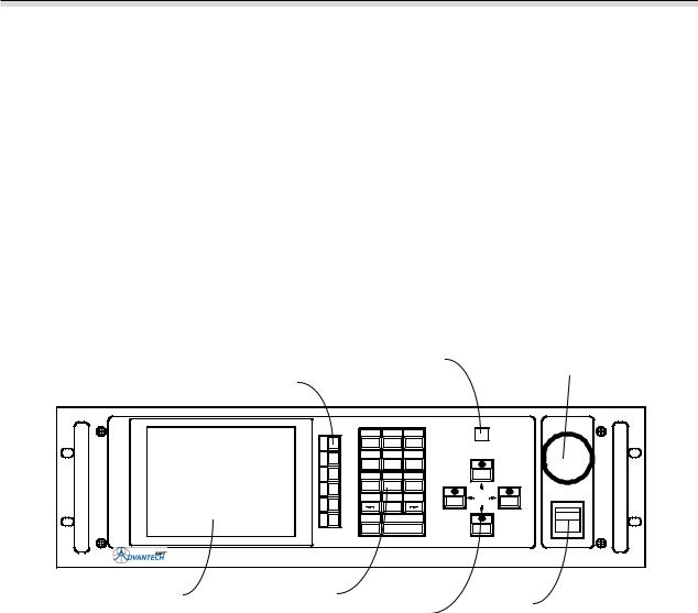
FRONT PANEL
SYSTEM ALARM |
EMERGENCY STOP |
|
BUTTON |
||
INDICATOR |
||
|
MENU KEYS
|
|
SYSTEM ALARM |
EMERGENCY |
|
|
|
|
|
|
|
STOP |
1 |
2 |
3 |
|
4 |
5 |
6 |
7 |
8 |
9 |
|
MANUAL |
|
POWER |
|
CONTROL |
|
0 |
+ |
ENTER |
|
Intrac Antenna Controller |
INTRAC 305 |
|
LCD DISPLAY PANEL |
NUMERIC KEYPAD |
ON/OFF |
(STATUS LEDS on |
|
|
|
|
MANUAL CONTROL KEYS |
SWITCH |
DUAL PSU unit) |
|
||
|
|
LCD Display Panel |
This displays the current status of the INTRAC-305 and the |
|
selected menu which includes the labels for the menu keys. |
Menu Keys |
These six keys have functions dependant on the selected |
|
menu. The right side of the menu display indicates the |
|
function of each key for that menu. |
Numeric Keypad |
The keypad is used to enter or edit data into the INTRAC. |
|
The & keys move the cursor left and right. |
|
The +/- key is used to change the sign or, in some cases to |
|
insert a space character. |
Manual Control Keys |
For manual control of the antenna pointing when the INTRAC |
|
is in manual mode. |
System Alarm Indicator |
Illuminates when a primary alarm occurs and remains on until |
|
the cause of the alarm is cleared. |
Note. |
An active primary alarm disables antenna drive. |
© 2011 Advantech Wireless |
INTRAC-305 MANUAL - Issue 3.2 |
Page 7 |

OPERATION |
INTRAC-305 |
Emergency Stop Button |
Pressing the button removes all drive from the antenna. The |
|
button locks in the safe position when pressed. To enable |
|
drive to return to the antenna the button must be rotated |
|
clockwise until it releases. |
On/Off Switch |
Illuminated rocker switch to apply power to the INTRAC-305. |
|
Illuminated when the INTRAC is on. On Dual Redundant |
|
PSU units the rocker switch is replaced by status LEDs. |
Dual Redundant Status Leds |
On Dual Redundant PSU units there is a green and red status |
|
LED for each PSU. Green indicates that the PSU is powered |
|
and working normally. Red indicates thjat the PSU is |
|
powered but faulty. When the PSU is unpowered both LEDs |
|
will be off. The INTRAC will operate correctly when at least 1 |
|
green LED is illuminated. |
THE MENU STRUCTURE
HOME
STANDBY |
NEW MODE |
FUNCTION |
ALARMS |
REMOTE LOCAL |
MANUAL/ |
GOTO |
AUTO CONTINUE |
AUTO NEW MODEL |
STOW |
|
|
|
|
GOTO POSITION |
SEARCH |
GOTO SATELLITE |
MODELS |
CONFIGURATION |
SYSTEM |
SETUP |
|||||||
|
|
|
|
|
|
|
|
|
|
|
|
|
|
RAPID MODEL GENERATE |
|
|
|
BEACON POL not avail |
|
|
CONTRAST & BRIGHTNESS |
|
|
|
|
|
|
|
|
|||
|
|
|
PROGRAM TRACK |
|
|
|
BEACON FREQUENCY |
|
|
FINE TUNE |
|
|
|
|
|
|
|
||||
|
|
|
|
|
|
|
|
|
||
|
|
|
|
|
|
|
|
|
|
|
|
|
|
RESERVE MODEL |
|
|
|
EDIT SATELLITE |
|
|
STATION COORDINATES |
|
|
|
|
|
|
|
||||
|
|
|
EDIT IESS-412 |
|
|
|
SOFT LIMITS |
|
|
|
|
|
|
|
|
|
|
|
DATE & TIME |
||
|
|
|
|
|
|
|
||||
|
|
|
|
|
|
EXTENDED AZ not avail |
|
|
||
|
|
|
EDIT NORAD |
|
|
|
|
|
||
|
|
|
|
|
|
|
|
AZ& EL BEAMWIDTH |
||
|
|
|
|
|
|
|
||||
|
|
|
|
|
|
DIAGNOSTICS ON |
|
|
||
|
|
|
EDIT STAR TRACK |
|
|
|
|
|
||
|
|
|
|
|
|
|
|
|||
|
|
|
|
|
|
|
|
|
||
|
|
|
|
|
|
|
|
|
|
|
|
|
|
EDIT SATELLITE |
|
|
|
DIAGNOSTICS OFF |
|
|
STOW SETUP |
|
|
|
|
|
|
|
|
|||
|
|
|
|
|
|
|
|
FITTED OPTIONS |
||
|
|
|
|
|
|
BEACON THRESHOLD |
|
|
||
|
|
|
CLEAR MODELS |
|
|
|
|
|
||
|
|
|
|
|
|
|
|
|||
|
|
|
|
|
|
|
|
|
||
selected by menu list
The diagram above shows the various menus in a “tree” structure.
The menu headings in heavy type are selected by the six menu keys from the “HOME” menu. The headings in the box below “NEW MODE” are selected by the menu keys in NEW
MODE. The shaded area headings are sub menus of the MODELS, CONFIGURATION and SYSTEM SETUP menus.
They are accessed by using the “Next Field” menu key from the appropriate menu followed by the “ENTER” key on the numeric keypad.
Page 8 |
INTRAC-305 MANUAL - Issue 3.2 |
©2011 Advantech Wireless |

3
INTRAC-305 |
|
OPERATION |
Example |
To select “STOW SETUP” from the HOME menu :- |
|
|
FUNCTION |
(menu key) |
|
SYSTEM SETUP |
(menu key) |
|
NEXT FIELD |
(menu key) press five times. |
|
ENTER |
(numeric keypad) |
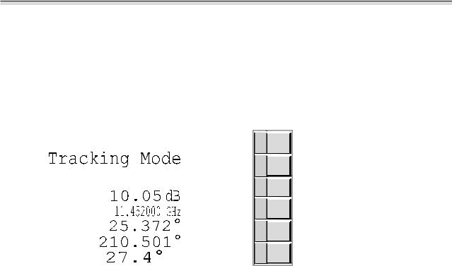
THE MENU SCREEN
|
A typical menu display screen is shown above. In this |
|
example it is the “Goto Position” used to drive the antenna to |
|
a particular pointing angle. |
|
The top section shows the current mode of the INTRAC, |
|
whether the control is remote or local and the various pointing |
|
angles of the antenna. |
Note |
On some screens (e.g., HOME) the current status display |
|
expands to fill the lower part of the screen. |
|
Down the right side of the screen are the current functions of |
|
the six menu keys. |
|
Above the key labels is the menu type designator, i.e., one of |
|
the six main menu headings. |
|
The main part of the display relates to the selected menu. |
|
The individual menus are described on the following pages in |
|
order of the menu tree shown above. The order is from left to |
|
right and taking the branches as they come. |
© 2011 Advantech Wireless |
INTRAC-305 MANUAL - Issue 3.2 |
Page 9 |

OPERATION |
INTRAC-305 |
On the next page is an alphabetical index of the menus to assist in the quick location of a specific function.
ALPHABETICAL INDEX OF MENUS
Alarms ...................................................................... |
48 |
Auto Continue ...................................................................... |
21 |
Auto New Model ...................................................................... |
22 |
Az & El Beamwidth ...................................................................... |
36 |
Beacon Frequency ...................................................................... |
24 |
Beacon Threshold ...................................................................... |
29 |
Beamwidth Az & El ...................................................................... |
36 |
Brightness & Contrast ...................................................................... |
30 |
Clear Models ...................................................................... |
47 |
Configuration ...................................................................... |
23 |
Contrast & Brightness ...................................................................... |
30 |
Date & Time Setting ...................................................................... |
34 |
Diagnostics On/Off ...................................................................... |
28 |
Edit IESS-412 ...................................................................... |
43 |
Edit NORAD ...................................................................... |
44 |
Edit Satellite Table ...................................................................... |
25 |
Edit Star Track ...................................................................... |
45 |
Fine Tune Offsets ...................................................................... |
32 |
Fine Tune Sense ...................................................................... |
31 |
Fitted Options ...................................................................... |
39 |
Function ...................................................................... |
23 |
Goto Position ...................................................................... |
18 |
Page 10 |
INTRAC-305 MANUAL - Issue 3.2 |
©2011 Advantech Wireless |

3
INTRAC-305 |
OPERATION |
Goto Satellite |
...................................................................... 20 |
Home |
...................................................................... 14 |
IESS-412 Edit |
...................................................................... 43 |
Local/Remote |
...................................................................... 49 |
Manual/Stow |
...................................................................... 17 |
Models |
......................................................................40 to 47 |
New Mode |
...................................................................... 16 |
NORAD Edit |
...................................................................... 44 |
Program Track |
...................................................................... 41 |
Rapid Model Generate |
...................................................................... 40 |
Remote/Local |
...................................................................... 49 |
Reserve Model |
...................................................................... 42 |
Satellite Table Edit |
...................................................................... 25 |
Search |
...................................................................... 19 |
Select Stow Use |
...................................................................... 38 |
Show Alarms |
...................................................................... 48 |
Standby |
...................................................................... 15 |
Star Track Edit |
...................................................................... 45 |
Station Co-ordinates |
...................................................................... 33 |
Soft Limits |
...................................................................... 26 |
Stow |
...................................................................... 17 |
Stow Set-up |
...................................................................... 37 |
System Set-up |
......................................................................30 to 39 |
Time Rate Correction |
...................................................................... 35 |
Time Setting |
...................................................................... 34 |
X2 Setup |
…………………………………………………… 27 |
© 2011 Advantech Wireless |
INTRAC-305 MANUAL - Issue 3.2 |
Page 11 |
OPERATION |
INTRAC-305 |
HOME
|
|
|
|
|
|
|
|
|
|
|
|
|
|
|
|
|
|
Home |
|
|
|
|
|
|
|
|
|
|
|
|
|
Current Mode |
Local |
|
Standby |
|
|||
|
|
|
|
|
|
||||
|
|
|
|
|
|
|
|
|
|
|
|
|
|
|
|
|
|
|
|
|
|
|
|
|
|
|
|
|
|
|
|
|
|
|
|
|
|
New |
|
|
|
|
|
|
|
|
|
Mode |
|
|
Beac Level |
|
|
|
|
|
|
||
|
|
|
Function |
|
|||||
|
Beac Freq |
|
|
|
|||||
|
|
|
|
|
|||||
|
|
|
|
|
|
|
|
|
|
|
El |
Angle |
|
|
Show |
|
|||
|
|
|
|
|
|
|
|
Alarms |
|
|
Az |
Angle |
|
|
|
|
|||
|
|
Select |
|
||||||
|
|
|
|
|
|
|
|
|
|
|
Pol Angle |
|
|
Remote |
|
||||
|
|
|
|
|
|
|
|
|
|
|
|
|
|
|
|
|
|
|
|
1 |
2 |
3 |
4 |
5 |
6 |
puts the antenna control system into STANDBY mode and skips to the HOME menu
(not used)
moves to the New Mode menu (not available when in remote Control Mode)
moves to the 1st ‘Function’ menu(not available when in remote Control Mode)
shows the Alarms menu ie the currently active alarms
toggles the INTRAC between Remote and Local control modes
Path |
HOME |
Note |
This menu can be reached directly from almost every menu |
|
by pressing Menu Key 2. |
Description |
This is the root Menu as shown in the menu structure diagram |
|
on page 10. |
|
It is from here that the five main menus are accessed directly |
|
by use of the Menu Keys. |
Page 12 |
INTRAC-305 MANUAL - Issue 3.2 |
©2011 Advantech Wireless |
3
INTRAC-305 |
OPERATION |
STANDBY
|
|
|
|
|
|
|
|
|
|
|
|
|
|
|
|
|
|
Home |
|
|
|
|
|
|
|
|
|
|
|
|
|
Current Mode |
Local |
|
Standby |
|
|||
|
|
|
|
|
|
||||
|
|
|
|
|
|
|
|
|
|
|
|
|
|
|
|
|
|
|
|
|
|
|
|
|
|
|
|
|
|
|
|
|
|
|
|
|
|
New |
|
|
|
|
|
|
|
|
|
Mode |
|
|
|
Beac Level |
|
|
|
|
|
|
|
|
|
|
|
|
Function |
|
|||
|
|
Beac Freq |
|
|
|
||||
|
|
|
|
|
|
||||
|
|
|
|
|
|
|
|
|
|
|
|
El |
Angle |
|
|
Show |
|
||
|
|
|
|
|
|
|
|
Alarms |
|
|
|
Az |
Angle |
|
|
|
|
||
|
|
|
|
Select |
|
||||
|
|
|
|
|
|
|
|
|
|
|
|
|
|
|
|
|
|
Remote |
|
|
|
Pol Angle |
|
|
(Local) |
|
|||
|
|
|
|
|
|
|
|
|
|
|
|
|
|
|
|
|
|
|
|
1 |
2 |
3 |
4 |
5 |
6 |
puts the antenna control system into STANDBY mode
moves to the New Mode menu (not available when in remote Control Mode)
moves to the 1st ‘Function’ menu(not available when in remote Control Mode)
shows the Alarms menu ie the currently active alarms
toggles the INTRAC between Remote and Local control modes
Path |
STANDBY |
Note |
This menu can be reached directly from almost every menu |
|
by pressing Menu Key 1. |
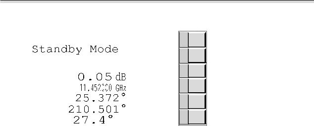
Description |
Standby is a monitoring but no movement mode. |
|
The antenna is not driven in this mode but its position and the |
|
beacon signal strength are monitored and displayed. |
|
External inputs are also monitored and any appropriate |
|
alarm(s) become active. The System Alarm indicator will |
|
illuminate and the alarms may be viewed by pressing “Show |
|
Alarms”. |
|
Standby mode is entered in one of three ways :- |
|
by being selected by the operator using Menu Key 1. |
|
by a primary alarm becoming active. |
|
at the end of a Goto move or at the end of a search. |
© 2011 Advantech Wireless |
INTRAC-305 MANUAL - Issue 3.2 |
Page 13 |
OPERATION |
INTRAC-305 |
NEW MODE
|
|
|
New Mode |
|
Current Mode |
Local |
Standby |
1 |
|
|
|
|
||
|
|
|
Home |
2 |
|
|
|
|
|
|
|
|
Manual |
3 |
|
|
|
/Stow |
|
Beac Level |
|
|
|
|
Beac Freq |
|
Goto |
4 |
|
|
|
|
||
El |
Angle |
|
Auto |
5 |
|
|
|
Continue |
|
Az |
Angle |
|
Auto |
|
|
|
|
6 |
|
|
|
|
New |
|
Pol Angle |
|
Model |
|
|
puts the antenna control system into STANDBY mode and skips to the HOME menu
skips to the Home (root) menu
moves to the Manual/Stow menu
moves to the 1st ‘Goto’ menu ie Goto
Position
resumes tracking using the INTRAC’S current model
clears the INTRAC’S current model and starts learning a new model
Path |
Menu key 3 from the “HOME” or “STANDBY” menus. |
Description |
Displays the current mode and antenna pointing angles on |
|
the full screen. |
|
This is the entry menu for moving the antenna. |
|
Menu key 3 leads to the Manual antenna control and antenna |
|
stow menu. |
|
Menu key 4 leads to the “Goto” menu for “Goto Position”, |
|
“Goto Satellite” and “Search”. |
|
Menu key 5 resumes tracking using the current model. |
|
(Assuming that there is a valid model). |
|
Menu key 6 clears the existing model and starts learning a |
|
new model for the satellite at the current pointing. |
Page 14 |
INTRAC-305 MANUAL - Issue 3.2 |
©2011 Advantech Wireless |
3
INTRAC-305 |
OPERATION |
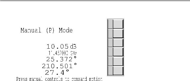
MANUAL/STOW
|
|
|
|
|
|
|
|
|
|
|
|
|
|
|
|
|
|
|
|
Manual |
|
|
|
|
|
|
|
|
|
|
|
|
|
|
Current Mode |
Local |
|
Standby |
|
||||
|
|
|
|
|
|
|||||
|
|
|
|
|
|
|
|
|
|
|
|
|
|
|
|
|
|
|
|
Home |
|
|
|
|
|
|
|
|
|
|
|
|
|
|
|
|
|
|
|
|
|
New |
|
|
|
|
|
|
|
|
|
|
Mode |
|
|
|
Beac Level |
|
|
|
|
|
|
||
|
|
|
|
|
Stow/ |
|
||||
|
|
|
|
|
|
|
|
|
|
|
|
|
Beac Freq |
|
|
Unstow |
|
||||
|
|
|
|
|
|
|||||
|
|
|
|
|
|
|
|
|
|
|
|
|
|
|
|
|
|
|
|
Select |
|
|
|
El |
Angle |
|
|
|
|
|
||
|
|
|
|
|
|
|
Az&El |
|
||
|
|
|
|
|
|
|
|
|
or Pol |
|
|
|
Az |
Angle |
|
|
|
|
|
|
|
|
|
|
|
|
|
|
Latch |
|
||
|
|
|
|
|
|
|
|
|
|
|
|
|
Pol Angle |
|
|
Drive |
|
||||
|
|
|
|
|
|
|||||
|
|
|
|
|
|
|
|
|
|
|
|
|
|
|
|
|
|
|
|
|
|
1 |
2 |
3 |
4 |
5 |
6 |
puts the antenna control system into STANDBY mode and skips to the HOME menu
skips to the Home (root) menu
moves to the New Mode menu (not available when in remote Control Mode)
Stows or Unstows (toggle) the antenna depending on its current state
(toggle) selects whether manual control buttons drive Az/El or Pol axes
latches the currently operated Manual Drive button until pressed a second time
Path |
HOME - NEW MODE - MENU KEY 3 |
Description |
|
Manual |
This menu screen enables the antenna pointing direction to |
|
be changed manually by use of the Manual Control Keys on |
|
the front panel. Menu key 5 enables either azimuth & |
|
elevation or the polarisation motors to be driven. |
|
Azimuth is driven by the left and right manual keys. |
|
Elevation is driven by the upper and lower manual keys. |
|
Polarisation is driven by the left (ccw) and right (cw) manual |
|
keys. |
|
Menu key 6 latches which ever manual key is pressed and |
|
drives at an increased speed. (useful for large distance |
|
moves) Pressing key 6 again releases the latching effect. |
Stow |
Menu key 4 (alternate functions) causes the antenna to be |
|
driven to the pre-set stow position (via the preliminary stow |
|
position) and, where appropriate, the stow pins to be driven |
|
into locking position. |
|
If the antenna is “stowed” key 4 causes the stow pins to be |
|
withdrawn, where appropriate, and the antenna to drive to the |
|
preliminary stow position. (see Stow Setup) |
Notes |
The Drive Fail alarm does not work in Manual (P) mode. |
|
The antenna may be driven through azimuth 0 (North) in |
|
Manual (P) mode (azimuth 180 [South] in Southern |
|
Hemisphere). |
|
Manual (P) mode is local (front panel) control as opposed to |
|
remote manual control which is Manual (A) Mode. |
© 2011 Advantech Wireless |
INTRAC-305 MANUAL - Issue 3.2 |
Page 15 |

OPERATION |
INTRAC-305 |
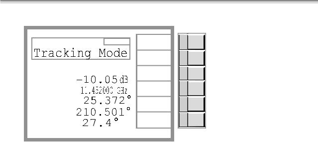
GOTO (Position)
|
|
|
|
Mode |
|
Current Mode |
Tracking |
|
|
||
Control State |
Local |
|
Standby |
1 |
|
Beac Freq |
11.452000 GHz |
|
|
||
Beac Level |
-10.05 |
dB |
|
|
|
El |
Angle |
25.37 |
|
|
|
Az |
Angle |
210.50 |
|
Home |
2 |
Pol |
Angle |
27.4 |
|
|
|
|
|
|
|
New |
3 |
|
|
|
|
Mode |
|
El Angle |
|
|
Search |
4 |
|
Az Angle |
|
|
Goto |
|
|
|
|
|
|
5 |
|
Pol Angle |
|
|
Satellite |
||
|
|
|
|
||
Beac Freq |
|
MHz |
Next |
6 |
|
|
Field |
||||
|
|
|
|
|
|
Press EN to go to position |
|
|
|||
puts the antenna control system into STANDBY mode and skips to the HOME menu
skips to the Home (root) menu
skips to the New Mode menu
skips to the Search menu
skips to the Goto Satellite menu
moves the highlight box to the next field in the current menu
Path |
HOME - NEW MODE - MENU KEY 4 |
Note |
Pressing menu key 4 (Goto) on the New Mode menu leads to |
|
the Goto Position (as opposed to Goto Satellite) menu. Goto |
|
Satellite and Search are accessed from this (Goto Position) |
|
menu by Menu Keys 5 and 4 respectively. |
Description |
Used to drive the antenna to the co-ordinates displayed. |
|
The co-ordinates can be set by using menu key 6 (Next Field) |
|
to step through the three angles and the Beacon Frequency. |
|
The co-ordinate enclosed in the box can be edited from the |
|
numeric keypad. The & keys are used to move the |
|
cursor to the desired character. |
|
Pressing the ENTER key causes the antenna to commence |
|
driving to the set co-ordinates. When the antenna reaches |
|
the position the INTRAC enters STANDBY Mode. |
Page 16 |
INTRAC-305 MANUAL - Issue 3.2 |
©2011 Advantech Wireless |

3
INTRAC-305 |
OPERATION |
SEARCH
Current Mode |
Tracking |
|
Control State |
Local |
|
Beac Freq |
11.500000GHz |
|
El Angle |
25.55 |
|
Az Angle |
235.45 |
|
Pol Angle |
25.63 |
|
SEARCH
|
Nom. Angle |
|
Box Size |
|
|
|
|
|
|
El |
|
-027.334 |
|
2.0 |
|
|
|
|
|
Az |
|
178.550 |
|
2.0 |
Dwell Time |
25secs |
|||
Beac Freq 12.250500GHz Press EN to begin search
Mode |
|
Standby |
1 |
|
|
Home |
2 |
|
|
Goto |
|
Position |
3 |
|
4 |
Goto |
|
Satellite |
5 |
Next |
6 |
Field |
puts the antenna control system into STANDBY mode and skips to the HOME menu
skips to the Home (root) menu
skips to the Goto Position menu
(not used)
skips to the Goto Satellite menu
moves the highlight box to the next field in the current menu
Path |
HOME - NEW MODE - GOTO (Position) - MENU KEY 4 |
Description |
Used to search a specific area of sky for the strongest signal |
|
on the beacon frequency. |
|
The antenna may be driven to the nominal co-ordinates of the |
|
required satellite by either the Goto Position or Goto Satellite |
|
commands or manually. Alternatively the Az & El co- |
|
ordinates can be entered on this screen. |
|
Using Menu Key 6 (Next Field) and the numeric keys the |
|
satellite's position and beacon frequency may be entered. |
|
The search box size and the antenna dwell time are also |
|
entered in the same manner. |
|
The box size parameters are either side of the nominal angle |
|
thus entering 2 will cause a 4 scan. |
|
The dwell time is the time that the antenna will remain at each |
|
step. It is the lock time of the beacon receiver. For the IBR-L |
|
(The Signal Processors supplied Integrated Beacon Receiver) |
|
the default dwell time of 25 seconds is correct. |
|
Once all the co-ordinates are set pressing ENTER will start |
|
the search. The antenna will drive to the nearest corner of |
|
the search box before commencing the search pattern. |
© 2011 Advantech Wireless |
INTRAC-305 MANUAL - Issue 3.2 |
Page 17 |
 Loading...