


 Loading...
Advantech ADAM-6015, ADAM-6017, ADAM-6018, ADAM-6024, ADAM-6050 User guide
...
User Manual
ADAM-6000 Series
Ethernet-based Data Acquisition
and Control Modules

Copyright
The documentation and the software included with this product are copyrighted 2018 by Advantech Co., Ltd. All rights are reserved. Advantech Co., Ltd. reserves the right to make improvements in the products described in this manual at any time without notice. No part of this manual may be reproduced, copied, translated or transmitted in any form or by any means without the prior written permission of Advantech Co., Ltd. Information provided in this manual is intended to be accurate and reliable. However, Advantech Co., Ltd. assumes no responsibility for its use, nor for any infringements of the rights of third parties, which may result from its use.
Acknowledgements
Intel and Pentium are trademarks of Intel Corporation.
Microsoft Windows and MS-DOS are registered trademarks of Microsoft Corp. All other product names or trademarks are properties of their respective owners.
Product Warranty
Advantech warrants to you, the original purchaser, that each of its products will be free from defects in materials and workmanship for two years from the date of purchase.
This warranty does not apply to any products which have been repaired or altered by persons other than repair personnel authorized by Advantech, or which have been subject to misuse, abuse, accident or improper installation. Advantech assumes no liability under the terms of this warranty as a consequence of such events.
Because of Advantech’s high quality-control standards and rigorous testing, most of our customers never need to use our repair service. If an Advantech product is defective, it will be repaired or replaced at no charge during the warranty period. For out- of-warranty repairs, you will be billed according to the cost of replacement materials, service time and freight. Please consult your dealer for more details.
If you think you have a defective product, follow these steps:
1.Collect all the information about the problem encountered. (For example, CPU speed, Advantech products used, other hardware and software used, etc.) Note anything abnormal and list any onscreen messages you get when the problem occurs.
2.Call your dealer and describe the problem. Please have your manual, product, and any helpful information readily available.
3.If your product is diagnosed as defective, obtain an RMA (return merchandize authorization) number from your dealer. This allows us to process your return more quickly.
4.Carefully pack the defective product, a fully-completed Repair and Replacement Order Card and a photocopy proof of purchase date (such as your sales receipt) in a shippable container. A product returned without proof of the purchase date is not eligible for warranty service.
5.Write the RMA number visibly on the outside of the package and ship it prepaid to your dealer.
Part No. 2003600003 |
Edition 9 |
Printed in Taiwan |
August 2018 |
ADAM-6000 User Manual |
ii |

Declaration of Conformity
CE
This product has passed the CE test for environmental specifications when shielded cables are used for external wiring. We recommend the use of shielded cables. This kind of cable is available from Advantech. Please contact your local supplier for ordering information.
FCC Class A
Note: This equipment has been tested and found to comply with the limits for a Class A digital device, pursuant to part 15 of the FCC Rules. These limits are designed to provide reasonable protection against harmful interference when the equipment is operated in a commercial environment. This equipment generates, uses, and can radiate radio frequency energy and, if not installed and used in accordance with the instruction manual, may cause harmful interference to radio communications. Operation of this equipment in a residential area is likely to cause harmful interference in which case the user will be required to correct the interference at his own expense.
Technical Support and Assistance
1.Visit the Advantech web site at www.advantech.com/support where you can find the latest information about the product.
2.Contact your distributor, sales representative, or Advantech's customer service center for technical support if you need additional assistance. Please have the following information ready before you call:
–Product name and serial number
–Description of your peripheral attachments
–Description of your software (operating system, version, application software, etc.)
–A complete description of the problem
–The exact wording of any error messages
iii |
ADAM-6000 User Manual |

Safety Instructions
1.Read these safety instructions carefully.
2.Keep this User Manual for later reference.
3.Disconnect this equipment from any AC outlet before cleaning. Use a damp cloth. Do not use liquid or spray detergents for cleaning.
4.For plug-in equipment, the power outlet socket must be located near the equipment and must be easily accessible.
5.Keep this equipment away from humidity.
6.Put this equipment on a reliable surface during installation. Dropping it or letting it fall may cause damage.
7.The openings on the enclosure are for air convection. Protect the equipment from overheating. DO NOT COVER THE OPENINGS.
8.Make sure the voltage of the power source is correct before connecting the equipment to the power outlet.
9.Position the power cord so that people cannot step on it. Do not place anything over the power cord.
10.All cautions and warnings on the equipment should be noted.
11.If the equipment is not used for a long time, disconnect it from the power source to avoid damage by transient overvoltage.
12.Never pour any liquid into an opening. This may cause fire or electrical shock.
13.Never open the equipment. For safety reasons, the equipment should be opened only by qualified service personnel.
14.If one of the following situations arises, get the equipment checked by service personnel:
The power cord or plug is damaged.
Liquid has penetrated into the equipment.
The equipment has been exposed to moisture.
The equipment does not work well, or you cannot get it to work according to the user's manual.
The equipment has been dropped and damaged.
The equipment has obvious signs of breakage.
15.DO NOT LEAVE THIS EQUIPMENT IN AN ENVIRONMENT WHERE THE STORAGE TEMPERATURE MAY GO BELOW -20° C (-4° F) OR ABOVE 60° C (140° F). THIS COULD DAMAGE THE EQUIPMENT. THE EQUIPMENT SHOULD BE IN A CONTROLLED ENVIRONMENT.
16.CAUTION: DANGER OF EXPLOSION IF BATTERY IS INCORRECTLY REPLACED. REPLACE ONLY WITH THE SAME OR EQUIVALENT TYPE RECOMMENDED BY THE MANUFACTURER, DISCARD USED BATTERIES ACCORDING TO THE MANUFACTURER'S INSTRUCTIONS.
17.The sound pressure level at the operator's position according to IEC 704-1:1982 is no more than 70 dB (A).
DISCLAIMER: This set of instructions is given according to IEC 704-1. Advantech disclaims all responsibility for the accuracy of any statements contained herein.
ADAM-6000 User Manual |
iv |

Contents
Chapter 1 |
Understanding Your System .............. |
1 |
||
1.1 |
Introduction ............................................................................................... |
|
|
2 |
|
Figure 1.1 |
ADAM-6000 |
Module System Architecture .................. |
2 |
1.2 |
Major Features .......................................................................................... |
|
|
2 |
1.3 |
Specifications ............................................................................................ |
|
|
4 |
1.4 |
Dimensions ............................................................................................... |
|
|
4 |
|
Figure 1.2 |
ADAM-6000 |
Module Dimensions ............................... |
4 |
1.5 |
LED Status ................................................................................................ |
|
|
5 |
Chapter 2 |
Hardware Selection Guidelines.......... |
7 |
2.1 |
Selecting an I/O Module............................................................................ |
8 |
|
Table 2.1: I/O Selection Guidelines ............................................. |
8 |
2.2 |
Selecting a Link Terminal and Cable ........................................................ |
8 |
|
Figure 2.1 Connecting ADAM-6000 Modules to an Ethernet Ter- |
|
|
minal via Cable ........................................................... |
9 |
|
Table 2.2: Ethernet RJ-45 Port Pin Assignment Chart ................ |
9 |
2.3 |
Selecting an Operator Interface ................................................................ |
9 |
Chapter |
3 |
Hardware Installation Guide ............. |
11 |
||
|
3.1 |
Interface Introduction .............................................................................. |
12 |
||
|
3.2 |
Mounting Options |
.................................................................................... |
13 |
|
|
|
3.2.1 |
Panel Mounting ........................................................................... |
13 |
|
|
|
|
Figure 3.1 ........................ |
Panel Mounting Bracket Dimensions |
13 |
|
|
|
Figure 3.2 ......... |
How to Fix a Module on the Mounting Bracket |
13 |
|
|
3.2.2 |
DIN Rail Mounting....................................................................... |
14 |
|
|
|
|
Figure 3.3 .......... |
How to Fix a Module on the DIN Rail Adapter |
14 |
|
|
|
Figure 3.4 ..................... |
How to Secure a Module to a DIN Rail |
14 |
|
3.3 |
Wiring and Connections .......................................................................... |
15 |
||
|
|
3.3.1 |
Power Supply ...................................................................Wiring |
15 |
|
|
|
|
Figure 3.5 ................ |
How to Connect the Module Power Wires |
15 |
|
|
3.3.2 |
I/O Module .......................................................................Wiring |
15 |
|
Chapter 4 |
Introduction to Analog ADAM-6000 I/O |
|||
|
Modules17 |
|
||
4.1 |
Analog Input Modules ............................................................................. |
18 |
||
4.2 |
ADAM-6015 7-ch Isolated RTD Input Module......................................... |
18 |
||
|
4.2.1 |
Specifications.............................................................................. |
18 |
|
|
4.2.2 |
Application Wiring ....................................................................... |
20 |
|
|
|
Figure 4.1 |
ADAM-6015 RTD Input Wiring ................................. |
20 |
|
4.2.3 |
Address Assignment ................................................................... |
20 |
|
4.3 |
ADAM-6017 8-ch Analog Input/2-ch Digital Output Module.................... |
20 |
||
|
4.3.1 |
Specifications.............................................................................. |
20 |
|
|
|
Figure 4.2 |
ADAM-6017 Jumper Switches.................................. |
22 |
|
4.3.2 |
Application Wiring ....................................................................... |
23 |
|
|
|
Figure 4.3 ADAM-6017 Analog Input Wiring............................. |
23 |
|
|
|
Figure 4.4 |
ADAM-6017 Analog Input Type Setting.................... |
23 |
|
|
Figure 4.5 |
ADAM-6017 Digital Output Wiring ............................ |
23 |
|
4.3.3 |
Address Assignment ................................................................... |
24 |
|
v |
ADAM-6000 User Manual |

|
4.4 |
ADAM-6018 Isolated Thermocouple Input/8-ch Digital Output Module |
.. 24 |
||
|
|
|
Figure 4.6 |
ADAM-6018 8-ch Thermocouple Input..................... |
24 |
|
|
4.4.1 |
Specifications.............................................................................. |
24 |
|
|
|
4.4.2 |
Application Wiring ....................................................................... |
26 |
|
|
|
|
Figure 4.7 |
ADAM-6018 Thermocouple Input Wiring.................. |
26 |
|
|
|
Figure 4.8 |
ADAM-6018 Digital Output Wiring............................ |
26 |
|
|
4.4.3 |
Address Assignment................................................................... |
26 |
|
|
4.5 |
ADAM-6024 12-ch Isolated Universal I/O Module .................................. |
26 |
||
|
|
4.5.1 |
Specifications.............................................................................. |
27 |
|
|
|
|
Figure 4.9 |
ADAM-6024 Jumper Settings................................... |
28 |
|
|
4.5.2 |
Application Wiring ....................................................................... |
29 |
|
|
|
|
Figure 4.10ADAM-6024 Analog I/O Wiring................................. |
29 |
|
|
|
|
Figure 4.11ADAM-6024 Digital Input Wiring............................... |
29 |
|
|
|
|
Figure 4.12ADAM-6024 Digital Output Wiring............................ |
30 |
|
|
|
4.5.3 |
Address Assignment................................................................... |
30 |
|
Chapter |
5 |
Introduction to Digital ADAM-6000 I/O |
|||
|
|
Modules31 |
|
||
|
5.1 |
Digital I/O and Relay Modules ................................................................ |
32 |
||
|
5.2 |
ADAM-6050 18-ch Isolated Digital I/O Module ....................................... |
32 |
||
|
|
5.2.1 |
Specifications.............................................................................. |
32 |
|
|
|
5.2.2 |
Application Wiring ....................................................................... |
33 |
|
|
|
|
Figure 5.1 |
ADAM-6050 Digital Input Wiring............................... |
33 |
|
|
|
Figure 5.2 |
ADAM-6050 Digital Output Wiring............................ |
33 |
|
|
5.2.3 |
Address Assignment................................................................... |
34 |
|
|
5.3 |
ADAM-6051 14-ch Isolated Digital I/O Module w/2-ch Counter.............. |
34 |
||
|
|
5.3.1 |
Specifications.............................................................................. |
34 |
|
|
|
5.3.2 |
Application Wiring ....................................................................... |
35 |
|
|
|
|
Figure 5.3 |
ADAM-6051 Digital Input Wiring............................... |
35 |
|
|
|
Figure 5.4 |
ADAM-6051 Counter (Frequency) Input................... |
35 |
|
|
|
Figure 5.5 |
ADAM-6051 Digital Output Wiring............................ |
36 |
|
|
5.3.3 |
Address Assignment................................................................... |
36 |
|
|
5.4 |
ADAM-6052 16-ch Source-Type Isolated Digital I/O Module.................. |
36 |
||
|
|
5.4.1 |
Specifications.............................................................................. |
36 |
|
|
|
|
Figure 5.6 |
ADAM-6052 Jumper Settings................................... |
37 |
|
|
5.4.2 |
Application Wiring ....................................................................... |
38 |
|
|
|
|
Figure 5.7 |
ADAM-6052 Digital Input Wiring............................... |
38 |
|
|
|
Figure 5.8 |
ADAM-6052 Digital Output Wiring............................ |
39 |
|
|
5.4.3 |
Address Assignment................................................................... |
39 |
|
|
5.5 |
ADAM-6060 6-ch Digital Input/6-ch Relay Module ................................. |
39 |
||
|
|
5.5.1 |
Specifications.............................................................................. |
39 |
|
|
|
5.5.2 |
Application Wiring ....................................................................... |
41 |
|
|
|
|
Figure 5.9 |
ADAM-6060 Digital Input Wiring............................... |
41 |
|
|
|
Figure 5.10ADAM-6060 Relay Output Wiring............................. |
41 |
|
|
|
5.5.3 |
Address Assignment................................................................... |
41 |
|
|
5.6 |
ADAM-6066 6-ch Digital Input/6-ch Power Relay Module ...................... |
42 |
||
|
|
5.6.1 |
Specifications:............................................................................. |
42 |
|
|
|
5.6.2 |
Application Wiring ....................................................................... |
43 |
|
|
|
|
Figure 5.11ADAM-6066 Digital Input Wiring............................... |
43 |
|
|
|
|
Figure 5.12ADAM-6066 Relay Output Wiring............................. |
43 |
|
|
5.7 |
Digital Output Diagnostic Function.......................................................... |
44 |
||
|
|
5.7.1 How to Obtain the Digital Output Diagnostic Status ................... |
45 |
||
|
|
|
Figure 5.13Abnormal DO Diagnostic Status............................... |
45 |
|
|
|
|
Figure 5.14Normal DO Diagnostic Status .................................. |
46 |
|
Chapter |
6 |
System Configuration Guide ........... |
49 |
||
ADAM-6000 User Manual |
vi |

6.1 |
System Requirements............................................................................. |
50 |
||
6.2 |
Installing Adam/Apax .NET Utility ........................................................... |
50 |
||
6.3 |
Adam/Apax .NET Utility Overview........................................................... |
50 |
||
|
|
Figure 6.1 |
Adam/Apax .NET Utility Operation Window ............. |
51 |
|
6.3.1 |
Menu Bar |
.................................................................................... |
51 |
|
6.3.2 |
Toolbar........................................................................................ |
|
52 |
|
|
Figure 6.2 ............................... |
Adam/Apax .NET Utility Toolbar |
52 |
|
6.3.3 Module Tree ..........................................................Display Area |
53 |
||
|
|
Figure 6.3 .......... |
Adam/Apax .NET Utility Module Display Area |
53 |
|
6.3.4 |
Status Display ....................................................................Area |
53 |
|
|
6.3.5 Configuration .......................................of ADAM-6000 Modules |
53 |
||
|
|
Figure 6.4 ...... |
Adam/Apax .NET Utility - Searching for Devices |
54 |
|
6.3.6 |
Group Configuration.................................................................... |
62 |
|
|
6.3.7 |
I/O Configuration......................................................................... |
64 |
|
|
|
Figure 6.5 |
All - Channel, Individual Channel, and GCL Configura- |
|
|
|
............................................................. |
tion Controls |
64 |
6.4 |
Analog Input Modules ....(ADAM-6015, ADAM-6017, and ADAM-6018) |
65 |
||
|
6.4.1 |
All-Channel ...........................................................Configuration |
65 |
|
|
|
Figure 6.6 ........................ |
Channels Range Configuration Area |
65 |
|
|
Figure 6.7 ...........................................Analog Input Trend Log |
68 |
|
|
6.4.2 |
Individual ................................................Channel Configuration |
70 |
|
|
|
Figure 6.8 ................... |
Analog Input Alarm Mode Configuration |
70 |
6.5 |
Universal I/O Modules ......................................................(ADAM-6024) |
71 |
||
|
6.5.1 |
All-Channel ...........................................................Configuration |
71 |
|
|
|
Figure 6.9 ......................... |
ADAM - 6015 Channel Configuration |
72 |
|
|
Figure 6.10ADAM ...........................................-6024 Output Tab |
72 |
|
6.6Universal Digital I/O Modules (ADAM-6050, ADAM-6051- ADAM-6052,
|
|
ADAM-6060, ADAM-6066)...................................................................... |
|
73 |
|
|
|
6.6.1 |
All-Channel Configuration ........................................................... |
|
73 |
|
|
6.6.2 |
Individual Channel Configuration ................................................ |
|
74 |
|
|
|
Figure 6.11Digital Input Modes................................................... |
|
75 |
|
|
|
Figure 6.12Digital Output Modes ................................................ |
|
78 |
|
|
|
Figure 6.13Graph Explaining Low to High Delay Output Mode |
.. 80 |
|
|
|
|
Figure 6.14Graph Explaining Low to High Delay Output Mode .. |
81 |
|
|
6.7 |
Introduction to P2P Functions ................................................................. |
|
81 |
|
|
|
6.7.1 |
P2P Communication Modes ....................................................... |
|
82 |
|
|
|
Figure 6.15Basic Mode for P2P.................................................. |
|
82 |
|
|
|
Figure 6.16Advanced mode for P2P........................................... |
|
83 |
|
|
6.7.2 |
P2P Communication Methods .................................................... |
|
83 |
|
|
6.7.3 |
P2P Event Triggers..................................................................... |
|
83 |
|
6.8 |
How to Configure P2P Functions ............................................................ |
|
84 |
|
|
|
|
Figure 6.17Peer to Peer/Event Tab ............................................ |
|
84 |
|
|
6.8.1 |
Basic Mode Configuration........................................................... |
|
85 |
|
|
|
Figure 6.18P2P Basic Mode Configuration................................. |
85 |
|
|
|
6.8.2 |
Advanced Mode Configuration.................................................... |
|
86 |
|
|
|
Figure 6.19P2P Advanced Mode Configuration ......................... |
86 |
|
|
|
|
Figure 6.20Copy One Setting to Other Channels ....................... |
87 |
|
|
6.9 |
ADAM-6000 Web Server......................................................................... |
|
87 |
|
|
|
6.9.1 |
HTML 5 ....................................................................................... |
|
88 |
|
|
6.9.2 |
Java Applet Customization ......................................................... |
|
90 |
|
|
|
Figure 6.21Structure of the ADAM6060.jar file ........................... |
93 |
|
|
|
|
Figure 6.22Firmware Upgrade.................................................... |
|
93 |
Chapter |
7 |
Planning Your Application Program.... |
|
||
|
|
101 |
|
|
|
|
7.1 |
Introduction ........................................................................................... |
|
102 |
|
|
7.2 |
ADAM .NET Class Library..................................................................... |
|
102 |
|
|
|
|
Figure 7.1 Modifying ADAM-6050 .NET |
.................................. |
103 |
|
|
|
vii |
ADAM-6000 User Manual |
|

|
|
|
Figure 7.2 |
Execute the sample code and configure your ADAM |
|
|
|
|
|
module.................................................................... |
103 |
|
7.3 |
Modbus Protocol for ADAM-6000 Modules........................................... |
104 |
||
|
|
7.3.1 |
Modbus Protocol Structure ....................................................... |
104 |
|
|
|
7.3.2 Modbus Function Code Introductions ....................................... |
104 |
||
|
7.4 |
ASCII Commands for ADAM-6000 Modules......................................... |
109 |
||
|
|
7.4.1 |
ASCII Syntax ............................................................................ |
109 |
|
|
|
7.4.2 |
System Command Set.............................................................. |
109 |
|
|
|
7.4.3 Analog Input Command Set...................................................... |
113 |
||
|
|
7.4.4 Analog Input Alarm Command Set ........................................... |
124 |
||
|
|
7.4.5 Universal I/O Command Set ..................................................... |
129 |
||
|
|
7.4.6 Digital I/O Command Set .......................................................... |
135 |
||
|
7.5 |
SNMP for ADAM-6000 Modules ........................................................... |
138 |
||
|
|
7.5.1 |
ADAM MIB file .......................................................................... |
138 |
|
|
|
7.5.2 |
SNMP Trap Configuration......................................................... |
138 |
|
|
|
|
Figure 7.3 |
Trap Configuration Using Adam/Apax .NET Utility. 139 |
|
|
|
7.5.3 |
SNMP OID Value...................................................................... |
140 |
|
|
7.6 |
MQTT for ADAM-6000 modules ........................................................... |
141 |
||
|
|
7.6.1 |
Introduction of MQTT................................................................ |
141 |
|
|
|
7.6.2 MQTT Format for ADAM module.............................................. |
141 |
||
|
|
7.6.3 |
MQTT Configuration ................................................................. |
144 |
|
|
|
7.6.4 How to Start MQTT with ADAM-6000 Modules ........................ |
147 |
||
|
|
7.6.5 |
Real-Time Clock ....................................................................... |
149 |
|
|
|
7.6.6 SNTP Configuration Using Adam/Apax .NET Utility ................. |
149 |
||
|
|
7.6.7 SNTP Configuration Using ASCII Commands.......................... |
150 |
||
Chapter |
8 |
Graphic Condition Logic (GCL) ..... |
151 |
||
|
8.1 |
Overview ............................................................................................... |
|
152 |
|
|
8.2 |
GCL Configuration Environment ........................................................... |
152 |
||
|
|
|
Figure 8.1 |
GCL Configuration Environment ............................ |
153 |
|
|
|
Figure 8.2 |
Four Stages for One Logic Rule............................. |
154 |
|
8.3 |
Configuring the Four Stages of a Logic Rule ........................................ |
155 |
||
|
|
8.3.1 |
Input Condition Stage ............................................................... |
155 |
|
|
|
|
Figure 8.3 |
Input Condition Stage Configuration ...................... |
156 |
|
|
|
Figure 8.4 |
Scaling Function of Analog Input Mode.................. |
156 |
|
|
|
Figure 8.5 |
Engineer Unit and Current Value ........................... |
157 |
|
|
8.3.2 |
Logic Stage............................................................................... |
159 |
|
|
|
|
Figure 8.6 |
Logic Stage Configuration ...................................... |
159 |
|
|
8.3.3 |
Execution Stage........................................................................ |
160 |
|
|
|
|
Figure 8.7 |
Execution Stage Configuration............................... |
161 |
|
|
|
Figure 8.8 |
Send to Next Rule Function ................................... |
162 |
|
|
|
Figure 8.9 |
The Next Logic Rule............................................... |
162 |
|
|
8.3.4 |
Output Stage............................................................................. |
163 |
|
|
|
|
Figure 8.10Output Stage Configuration.................................... |
163 |
|
|
|
|
Figure 8.11Remote Message Output ....................................... |
166 |
|
|
8.4 |
Internal Flag for Logic Cascade and Feedback .................................... |
168 |
||
|
|
8.4.1 |
Logic Cascade .......................................................................... |
168 |
|
|
|
|
Figure 8.12Local Logic Cascade Architecture.......................... |
168 |
|
|
|
|
Figure 8.13Configuration of Logic Rule 1 ................................. |
168 |
|
|
|
|
Figure 8.14Configuration of Logic Rule 2 ................................. |
169 |
|
|
|
|
Figure 8.15Configuration of Logic Rule 3 ................................. |
169 |
|
|
|
|
Figure 8.16Distributed Logic Cascade ..................................... |
170 |
|
|
|
|
Figure 8.17Configuration of Logic Rule 1 ................................. |
170 |
|
|
|
|
Figure 8.18Configuration of Logic Rule 2 ................................. |
170 |
|
|
|
|
Figure 8.19Configuration of Logic Rule 3 ................................. |
170 |
|
|
|
8.4.2 |
Feedback .................................................................................. |
|
171 |
|
|
|
Figure 8.20Building Logic Feedback ........................................ |
171 |
|
|
8.5 |
Logic Download and Online Monitoring ................................................ |
171 |
||
ADAM-6000 User Manual |
viii |

|
|
Figure 8.21Online Monitoring Function..................................... |
|
172 |
|
|
Figure 8.22GCL Execution Sequence ...................................... |
|
173 |
8.6 |
Typical Applications with GCL............................................................... |
|
173 |
|
|
|
Figure 8.23Ladder Diagram for On/Off Control ........................ |
|
174 |
|
|
Figure 8.24GCL Logic for On/Off Control ................................. |
|
174 |
|
|
Figure 8.25Time Chart for Sequence Control........................... |
|
175 |
|
|
Figure 8.26GCL Logic for Sequence Control (Turns On in Se- |
|
|
|
|
quence and Remains On)....................................... |
|
175 |
|
|
Figure 8.27Time Chart for 12 Digital Inputs to 1 Digital Output 176 |
||
|
|
Figure 8.28GCL Logic for 12 Digital Inputs to 1 Digital Output. 176 |
||
|
|
Figure 8.29Time Chart for Flicker Applications......................... |
|
177 |
|
|
Figure 8.30GCL Logic for Flicker.............................................. |
|
177 |
|
|
Figure 8.31Time Chart for Rising Edge .................................... |
|
177 |
|
|
Figure 8.32Ladder Diagram for Rising Edge ............................ |
|
178 |
|
|
Figure 8.33GCL Logic for Rising Edge ..................................... |
|
178 |
|
|
Figure 8.34Time Chart for Falling Edge.................................... |
|
179 |
|
|
Figure 8.35Ladder Diagram for Falling Edge............................ |
|
179 |
|
|
Figure 8.36GCL Logic for Falling Edge .................................... |
|
179 |
|
|
Figure 8.37Time Chart for Sequence Control (Continuously Turn |
||
|
|
On and Off in Sequence)........................................ |
|
180 |
|
|
Figure 8.38GCL Logic for Sequence Control (Continuously Turn |
||
|
|
On and Off in Sequence)........................................ |
|
180 |
|
|
Figure 8.39GCL Logic for Event Trigger (Only Occurs Once) .. |
181 |
|
|
|
Figure 8.40Event Trigger Configuration (Only Occurs Once)... |
181 |
|
Appendix A |
Design Worksheets ......................... |
183 |
||
Appendix B |
Data Formats and I/O Ranges ........ |
187 |
||
B.1 |
ADAM-6000 Command Data Formats .................................................. |
|
188 |
|
|
|
Figure B.1 Request Comment Structure .................................. |
|
188 |
|
|
Figure B.2 Response Comment Structure ............................... |
|
188 |
B.2 |
ADAM-6000 I/O Modbus Mapping Tables ............................................ |
|
193 |
|
Appendix C |
Grounding Reference...................... |
223 |
||
C.1 |
Field Grounding and Shielding Application ........................................... |
|
224 |
|
|
C.1.1 |
Overview ................................................................................... |
|
224 |
C.2 |
Grounding ............................................................................................. |
|
224 |
|
|
C.2.1 The Earth as a Reference......................................................... |
|
224 |
|
|
|
Figure C.1 Thinking of the Earth as a Ground.......................... |
|
224 |
|
C.2.2 Frame Grounds and Grounding Bars........................................ |
|
225 |
|
|
|
Figure C.2 Grounding Bar ........................................................ |
|
225 |
|
|
Figure C.3 Figure C.3: Normal and Common Mode................. |
|
225 |
|
C.2.3 Normal Mode and Common Mode............................................ |
|
225 |
|
|
|
Figure C.4 Normal and Common Mode ................................... |
|
226 |
|
C.2.4 |
Wire impedance ........................................................................ |
|
226 |
|
|
Figure C.5 High Voltage Transmission.................................... |
|
226 |
|
|
Figure C.6 Wire Impedance ..................................................... |
|
227 |
|
C.2.5 |
Single-Point Grounding............................................................. |
|
227 |
|
|
Figure C.7 Single-Point Grounding .......................................... |
|
227 |
|
|
Figure C.8 Single point grounding............................................ |
|
227 |
C.3 |
Shielding ............................................................................................... |
|
228 |
|
|
C.3.1 |
Cable Shield.............................................................................. |
|
228 |
|
|
Figure C.9 Single Isolation Cable............................................. |
|
228 |
|
|
Figure C.10Double Isolation Cable ........................................... |
|
228 |
|
C.3.2 |
System Shielding ...................................................................... |
|
229 |
ix |
ADAM-6000 User Manual |

|
|
Figure C.11System Shielding ................................................... |
229 |
|
|
Figure C.12The Characteristics of the Cable............................ |
229 |
|
|
Figure C.13System Shielding (1).............................................. |
230 |
|
|
Figure C.14System Shielding (2).............................................. |
230 |
C.4 |
Noise Reduction Techniques ................................................................ |
230 |
|
|
|
Figure C.15Noise Reduction Techniques ................................. |
231 |
C.5 |
Checklist ............................................................................................... |
231 |
|
Appendix D |
REST for ADAM-6000...................... |
233 |
|
D.1 |
REST Introduction................................................................................. |
234 |
|
D.2 |
REST Resources for ADAM.................................................................. |
234 |
|
|
D.2.1 |
Analoginput............................................................................... |
234 |
|
D.2.2 |
Analogoutput............................................................................. |
235 |
|
D.2.3 |
Digitalinput ................................................................................ |
236 |
|
D.2.4 |
Digitaloutput.............................................................................. |
237 |
|
D.2.5 |
Counter ..................................................................................... |
238 |
ADAM-6000 User Manual |
x |
xi |
ADAM-6000 User Manual |

ADAM-6000 User Manual |
xii |

Chapter 1
1 Understanding Your
System
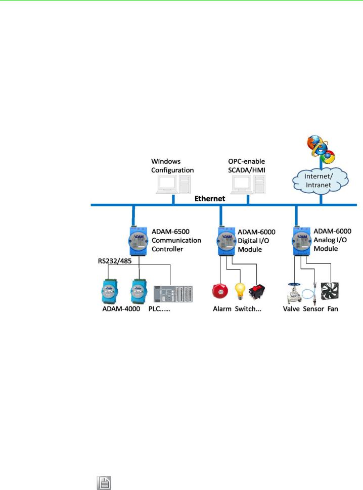
1.1 Introduction
ADAM-6000 series Ethernet-based data acquisition and control (DA&C) modules provide I/O, data acquisition, and networking capabilities in one module, allowing you to build a cost-effective distributed monitoring and control solution for a wide variety of applications. Through a standard Ethernet network, ADAM-6000 modules can retrieve I/O values from sensors and can publish them as real-time I/O values to networking nodes via LAN, intranet, or the Internet. With Ethernet-enabled technology, ADAM-6000 modules allow you to build up a cost-effective DA&C system for building automation, environmental monitoring, facility management, and e-manufacturing applications. Figure 1-1 gives a brief overview of a system architecture that can be adopted for ADAM-6000 modules.
Figure 1.1 ADAM-6000 Module System Architecture
1.2 Major Features
Ethernet-Enabled DA&C I/O Modules
ADAM-6000 modules are based on the widely utilized Ethernet networking standard, which is employed in most business environments. You can easily add ADAM-6000 series I/O modules to existing Ethernet networks or use them in new Ethernetenabled e-manufacturing networks. This series of modules supports 10/100 Mbps Ethernet and Modbus/TCP over TCP/IP for data connectivity, and UDP over Ethernet. With UDP/IP, ADAM-6000 series I/O modules can actively transmit data streams to up to eight Ethernet nodes. Through Ethernet networking, HMI/SCADA systems, and controllers, you can access and acquire real-time data from ADAM-6000 Ether- net-enabled DA&C modules. The data can then be integrated with business systems to derive valuable business information.
Note! Some intelligent functions are only provided with the ADAM-6000-CE version. See Appendix F for further details.
ADAM-6000 User Manual |
2 |

Intelligent I/O Modules
Upgraded from traditional I/O modules, all ADAM-6000 series modules have pre-built intelligent functions that can enhance system capabilities. For example, the digital input modules provide counter and totalizer functions; the digital output modules provide pulse output and delay output functions; the analog input modules provide descriptive statistical data calculations (e.g., min., max., and mean); and the analog output modules provide a PID loop control function.
Mixed I/O for All Applications
The ADAM-6000 series' mixed I/O design provides a cost-effective I/O option for application systems. The most commonly used I/O types for single-function units are available in a single module. This design concept not only saves I/O usage as well as costs, but it also speeds up I/O operations. For small DA&C system or standalone control units in medium-large systems, the ADAM-6000 series' mixed I/O design can easily fit your application needs with only one or two modules. With additional embedded control modules, these modules can be used to easily create a localized, less complex, and more distributed I/O architecture.
Remote Monitoring and Diagnosis
Previous differences in communication modes and data formats made it difficult to implement automation control and monitoring in IT-based infrastructure. In particular, users had to convert data to transform I/O datastreams from SCADA systems before transfer to a database or IT management system.
ADAM-6000 modules integrate the latest web language (HTML 5) and web-based architectural style (REST) with basic authentication for users to remotely acquire I/O data in any smart device web service without routing from the SCADA system. As an example, a smartphone web browser can now be used to remotely access an I/O module via HTTP.
Each ADAM-6000 module features a pre-built I/O module web page for displaying real-time I/O data, alarms, and module status via LAN or the Internet. Using any popular Internet browser, you can perform monitoring from both local and remote sites. Furthermore, web-enabled monitoring can be completed immediately without requiring any programming.
Modbus/TCP Protocol
ADAM-6000 modules support the widely used industry standard Modbus/TCP protocol, enabling you to connect with any Ethernet controllers or HMI/SCADA software that supports Modbus/TCP. Advantech also provides an OPC server for Modbus/TCP so that ADAM-6000 I/O module datastreams can be integrated with OPC clientenabled software, thus freeing you from having to develop new drivers.
Customized Web Page
Since ADAM-6000 modules have a default built-in web page, you can monitor and control the I/O status from any location by using Internet Explorer. Moreover, customized web pages can be uploaded to ADAM-6000 modules for individual applications. Advantech provides sample code in JavaScript* as a reference for you to design your own operator interface and then upload it to the specific ADAM-6000 modules via Adam/Apax .NET Utility.
Modbus/TCP Software Support
The firmware for ADAM-6000 modules has a built-in Modbus/TCP server. Advantech provides the ADAM .NET Class Library and Adam/Apax .NET Utility for module con-
<![endif]>System Your Understanding 1 Chapter
3 |
ADAM-6000 User Manual |
figuration and customization. You can configure ADAM modules using this utility, and it can be integrated with any human-machine (HMI) software that supports Modbus/ TCP. You can also purchase Advantech OPC Server to configure the Modbus/TCP settings.
1.3 Specifications
Ethernet |
10/100BASE-T |
|
Wiring |
UTP (Cat 5 or later) |
|
Bus Connection |
RJ45 modular jack |
|
Comm. Protocol |
Modbus/TCP on TCP/IP and UDP |
|
Data Transfer Rate |
Up to 100 Mbps |
|
Unregulated 10 to 30 VDC |
||
|
||
Status Indicator |
Power, CPU, Communication |
|
(Link, Collide, 10/100 Mbps, Tx, Rx) |
||
|
||
Case |
PC with captive mounting hardware |
|
Screw Terminal Block |
Accepts wire size #14-28 AWG, stripped length: 6.5 mm |
Note! Although the equipment is designed to operate below 30% humidity, static electricity problems are more common at lower humidity levels. Ensure you take adequate precautions when handling the equipment.
We recommend using grounding straps, anti-static floor coverings, and other protection measures if you use the equipment in low-humidity environments.
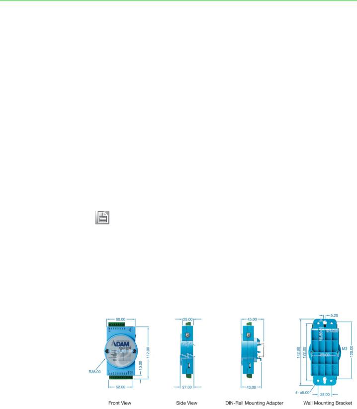
1.4 Dimensions
The following dimensions are given in millimeters. These dimensions are common for all ADAM-6000 modules.
Figure 1.2 ADAM-6000 Module Dimensions
ADAM-6000 User Manual |
4 |

1.5 LED Status
There are two LEDs on the front panel of ADAM-6000 modules. Each LED has two indicators to represent system status:
LED |
Color |
|
Indication |
Behavior |
|
|
|
|
Blink |
Module is normally running |
|
Status |
Orange (when Status and |
Red |
ON for 30s |
When user enable LOCATE |
|
|
Link are on at the same time) |
|
function |
||
Link |
|
Green |
ON |
Ethernet is connected |
|
Speed |
Orange (when speed and |
Red |
ON |
Ethernet speed is 100 Mbps |
|
COM |
COM are on at the same |
Green |
Blink |
Module is transmitting or |
|
time) |
receiving data |
||||
|
|
|
<![endif]>System Your Understanding 1 Chapter
5 |
ADAM-6000 User Manual |
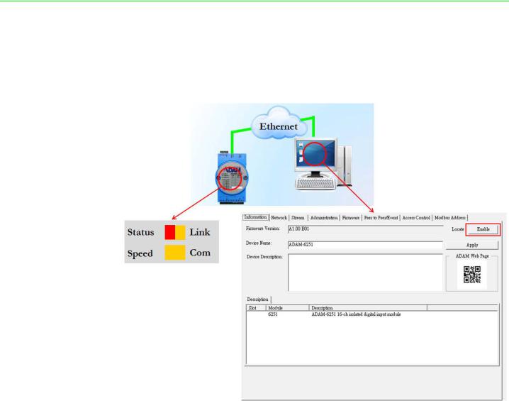
How to Locate Your Module
ADAM-6000 modules also have a locate function to help you physically identify a specific module that you may be looking for. When this function is enabled, the Status LED will remain red for 30 s. In Adam/Apax .NET Utility, you can enable the locate function by clicking Enable in the Information tab.
ADAM-6000 User Manual |
6 |

Chapter 2
2 Hardware Selection
Guidelines

2.1 Selecting an I/O Module
To organize an ADAM-6000 remote DA&C system, you will need to select I/O modules to act as an interface between the host PC and field devices or sensors. The following should be considered when deciding which I/O modules to select.
What types of I/O signals does your system use?
How many inputs and outputs does your system require?
How many modules are required for distributed I/O point arrangement?
How will you arrange the modules to handle I/O points in individual areas of the installation site?
How many hubs will you require to connect all of the modules?
What is the required voltage range for each I/O module?
What isolation environment is required for each I/O module?
What are the noise and distance limitations for each I/O module?
Examples of I/O module selection considerations are detailed in Table 2.1.
Table 2.1: I/O Selection Guidelines
Type of I/O |
Example Operations |
Explanation |
|
Module |
|||
|
|
||
Discrete input |
Selector switches, push buttons, photoelec- |
|
|
tric eyes, limit switches, circuit breakers, |
Input modules sense ON/OFF |
||
module and |
|||
proximity switches, level switches, motor |
|||
block I/O |
or OPENED/CLOSED signals |
||
starter contacts, relay contacts, and thumb- |
|||
module |
wheel switches |
|
|
|
|
||
Discrete output |
|
Output module signals inter- |
|
module and |
Alarms, control relays, fans, lights, horns, |
||
face with ON/OFF or |
|||
block I/O |
valves, motor starters, and solenoids |
||
OPENED/CLOSED devices |
|||
module |
|
||
|
|
||
|
Thermocouple signals, RTD signals, tem- |
Convert continuous analog |
|
Analog input |
perature transducers, pressure transducers, |
||
module |
load cell transducers, humidity transducers, |
signals into input values for a |
|
|
flow transducers, potentiometers. |
host device |
|
|
|
||
|
|
Set a host device’s output to |
|
Analog output |
Analog valves, actuators, chart recorders, |
analog signals (generally |
|
module |
electric motor drives, analog meters |
through transducers) for field |
|
|
|
devices |
2.2 Selecting a Link Terminal and Cable
Use an RJ-45 connector to connect the Ethernet port of ADAM-6000 modules to a hub. The cable employed for the connection should be a Cat 3 (10 Mbps) or Cat 5 (100 Mbps) UTP/STP cable, both of which comply with EIA/TIA 586 specifications. The maximum length between a hub and any ADAM-6000 module is 100 m (approx. 330 ft).
ADAM-6000 User Manual |
8 |
Figure 2.1 Connecting ADAM-6000 Modules to an Ethernet Terminal via Cable
Table 2.2: Ethernet RJ-45 Port Pin Assignment Chart
PIN Number |
Signal |
Function |
1 |
RD+ |
Receive (+) |
2 |
RD- |
Receive (-) |
3 |
TD+ |
Transmit (+) |
4 |
(Not used) |
- |
5 |
(Not used) |
- |
6 |
TD- |
Transmit (-) |
7 |
(Not used) |
- |
8 |
(Not used) |
- |
2.3 Selecting an Operator Interface
To complete your DA&C system, it is necessary to select an operator interface. Supporting the Modbus/TCP protocol, ADAM-6000 modules can easily be integrated into different systems for various applications.
The real-time status of ADAM-6000 modules can be read from a web page using the following browsers:
Microsoft Internet Explorer (version 9 or later)
Google Chrome (version 30 or later)
Safari (version 6 or later)
Mozilla Firefox (version 25 or later)
9 |
ADAM-6000 User Manual |
<![endif]>Guidelines Selection Hardware 2 Chapter

If you want to integrate ADAM-6000 modules with HMI software in a SCADA system, HMI software packages that support Modbus/TCP can be used. Examples are as follows:
Advantech PM Designer
Wonderware InTouch
Any software that supports the Modbus/TCP protocol
You can also purchase Advantech OPC Server, a highly user-friendly data exchange tool. Any HMI software designed with OPC Client can be employed to access ADAM6000 modules.
To develop your own applications, the Adam .NET Class Library is ideal for building up user interfaces.
With these ready-to-go software packages, tasks such as remote data acquisition, process control, historical trending, and data analysis require only a few keystrokes to utilize.
ADAM-6000 User Manual |
10 |

Chapter 3
3 Hardware Installation
Guide

3.1 Interface Introduction
Package Contents and System Requirements
Prior to installing ADAM-6000 modules, please check the following. The package should contain the following contents:
ADAM-6000 module with one bracket and DIN-rail adapter
ADAM-6000 module user manual
The minimum specifications for the host computer are listed as follows:
Microsoft Windows XP/7
32 MB RAM
20 MB of hard disk space
VGA color monitor
CD-ROM drive
Mouse or other pointing device
10/100 Mbps Ethernet card
The following equipment will also be required to complete the installation:
Ethernet hub (at least 2 ports)
Two Ethernet cables with an RJ-45 connector
Power supply for the ADAM-6000 module (+10 to 30 V, unregulated)
ADAM-6000 User Manual |
12 |
3.2 Mounting Options
ADAM-6000 modules are compact units that can be installed with a panel mounting bracket or a DIN rail mounting bracket.
3.2.1 Panel Mounting
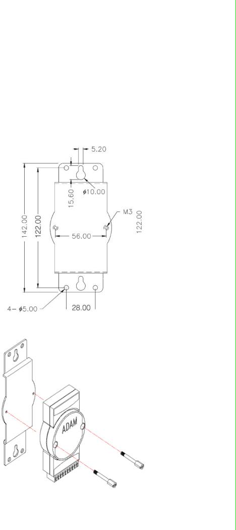
Before installing the ADAM-6000 module, you should determine the optimal placement in a panel or cabinet by referring the bracket dimensions shown in Figure 3.1. First, fix the bracket and then fix the ADAM-6000 module on the bracket, as shown in Figure 3.2.
Figure 3.1 Panel Mounting Bracket Dimensions
Figure 3.2 How to Fix a Module on the Mounting Bracket
<![endif]>Guide Installation Hardware 3 Chapter
13 |
ADAM-6000 User Manual |
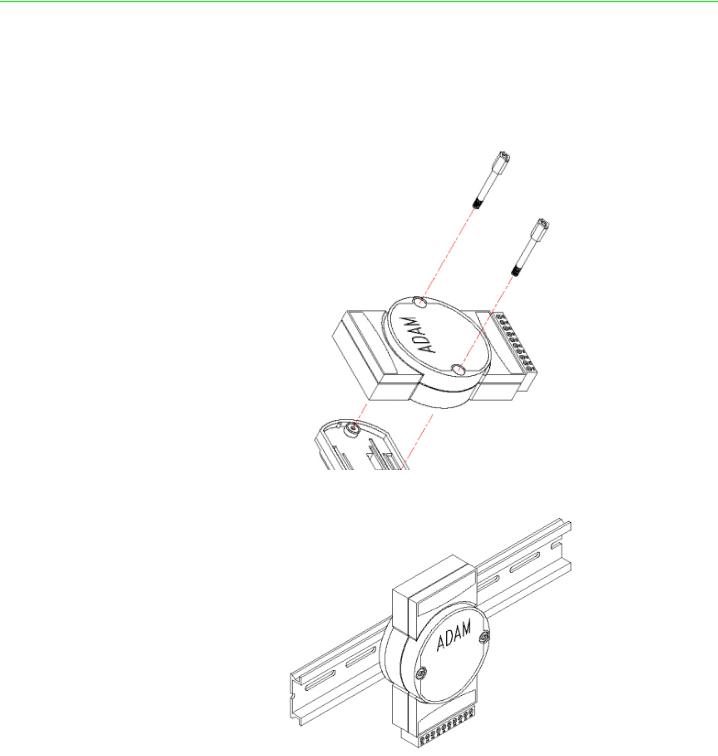
3.2.2 DIN Rail Mounting
The ADAM-6000 module can also be secured to a cabinet by using DIN rails. First, fix the ADAM-6000 module to the DIN rail adapter (Figure 3-3) and then secure it on the DIN rail (Figure 3-4). When mounting the module on the rail, you should consider using end brackets at each end of the rail in order to prevent the module from sliding.
Figure 3.3 How to Fix a Module on the DIN Rail Adapter
Figure 3.4 How to Secure a Module to a DIN Rail
ADAM-6000 User Manual |
14 |
3.3 Wiring and Connections
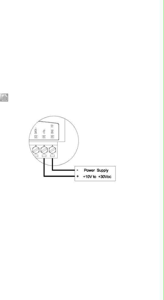
This section provides basic information on wiring the power supply, I/O units, and network connection.
3.3.1 Power Supply Wiring
Although ADAM-6000/TCP systems are designed for a standard industrial unregulated 24 VDC power supply, they accept any power unit that supplies input power
within the range of +10 to 30 VDC. Power supply ripple must be limited to 200 mV
peak-to-peak, and the immediate ripple voltage should be maintained between +10 and 30 VDC. Screw terminals +Vs and GND are for wiring the power supply.
Note! The wires should be at least 2 mm in diameter.
Figure 3.5 How to Connect the Module Power Wires
We advise using the following standard colors (which are also indicated on the modules) for the power lines:
+Vs (R) Red
GND (B)Black
3.3.2 I/O Module Wiring
A plug-in screw terminal block is used for the interface between I/O modules and field devices. The following information must be considered when connecting electrical devices to I/O modules.
The terminal block accepts Wire Size #14~28 AWG (stripped length: 6.5 mm)
Always use a continuous length of wire; do not combine wires
Use the shortest possible wire length
Use wire trays for routing where possible
Avoid running wires near high-energy wiring
Avoid running input wiring proximal to output wiring
Avoid creating sharp bends in the wires
<![endif]>Guide Installation Hardware 3 Chapter
15 |
ADAM-6000 User Manual |

ADAM-6000 User Manual |
16 |

Chapter 4
4 Introduction to Analog ADAM-6000 I/O Modules

4.1 Analog Input Modules
Analog input modules use an A/D converter to convert sensor voltage, current, thermocouple, and RTD signals into data, which are then translated into engineering units. When prompted by the host computer, the data are sent via standard 10/ 100BASE-T Ethernet or IEEE 802.11b WLAN. The current status can then be read using a pre-built webpage or any HMI software that supports Modbus/TCP. Analog input modules protect your equipment from ground loops and power surges by providing opto-isolation of the A/D input as well as transformer-based isolation.
4.2 ADAM-6015 7-ch Isolated RTD Input Module
The ADAM-6015 is a 16-bit, 7-ch RTD input module with programmable input ranges on all channels. It accepts various RTD inputs (PT100, PT1000, Balco 500, and Ni), and data are transmitted to the host computer in engineering units (°C). Each analog channel can be configured to an independent range, thus allowing individual channels to be used simultaneously in different applications.
4.2.1Specifications
Communication: 10/100BASE-T Ethernet
Supported protocols: Modbus/TCP,TCP/IP, UDP, HTTP, ICMP, DHCP, and ARP
Supports P2P and GCL (see Section 6.7 and Chapter 8)
High-Speed Mode (DE Version Only)
In high-speed mode, the maximum total sample rate is 1 kHz (i.e., if 7 channels are used, then the sampling rate will be 1000/7, which is approximately 142 Hz per channel). This will be influenced by the number of connected Modbus clients and the Ethernet quality. To maximize performance in high-speed mode, any channels that are not in use should be disabled; otherwise, the accuracy may be affected.
Note! When using a calibrator to simulate resistors in high-speed mode, no more than one channel should be enabled.
ADAM-6000 User Manual |
18 |
Loading...