


ADAM 4000
Data Acquisition Modules
User's Manual
ADAM 4000 Series
Data Acquisition Modules
User’s Manual
Copyright Notice
This document is copyrighted, 1997, by Advantech Co., Ltd. All rights are reserved. Advantech Co., Ltd., reserves the right to make improvements to the products described in this manual at any time without notice.
No part of this manual may be reproduced, copied, translated or transmitted in any form or by any means without the prior written permission of Advantech Co., Ltd. Information provided in this manual is intended to be accurate and reliable. However, Advantech Co., Ltd. assumes no responsibility for its use, nor for any infringements upon the rights of third parties, which may result from its use.
CE Notification
The ADAM-4000 series developed by Advantech Co., Ltd. has passed the CE test for environmental specifications when operated within an industrial enclosure (ADAM-4950-ENC). Therefore, in order to protect the ADAM modules from being damaged by ESD (Electric Static Discharge), we strongly recommend that the use of CE-compliant industrial enclosure products when using any ADAM module.
Acknowledgments
ADAM is a trademark of Advantech Co., Ltd.
IBM and PC are trademarks of International Business
Machines Corporation.
Edition 10.7
May 2008
Table of Contents
Chapter 1 Introduction ..….....……..................…..................…….. 1-1
1.1Overview .......................…................................….........….…… 1-2
1.2Applications ..................….........................…….............…....... 1-4
Chapter 2 Installation Guideline ...................….................…....... 2-1
2.1System Requirements to set up an ADAM network ..…....... 2-2
2.2Basic configuration and hook-up ....................……............... 2-6
2.3Baud rate and Checksum .................................……............... 2-9
2.4Multiple Module Hookup ...............................………............... 2-11
2.5Programming Example.....................................……................ 2-12
Chapter 3 I/O Modules ..................................................…............. 3-1
3.1ADAM-4011/4011D Thermocouple Input Modules ...…......... 3-3
3.2ADAM-4012 Analog Input Module ………………..…............... 3-10
3.3ADAM-4013 RTD Input Modules .......………………….…….... 3-15
3.4ADAM-4015 6-channel RTD Input Module .…………….......... 3-17
3.5ADAM-4015T 6-channel Thermistor Input Module ....…........ 3-20
3.6ADAM-4016 Analog Input/Output Module....………….…....... 3-22
3.7ADAM-4017/4017+/4018/4018M/4018+8-channelAnalogInput
|
Modules ........……………………………………………………..... 3-27 |
||
3.8 |
ADAM-4019+ |
8-channel Universal Analog Input |
|
|
Module ..................................................................................... |
|
3-37 |
3.9 |
ADAM-4021 Analog Output Module ........................…........... 3-41 |
||
3.10 ADAM-4024 |
4-channel Analog Output Module ................... |
3-44 |
|
3.11ADAM-4050 Digital I/O Module ……………………………..... 3-47
3.12ADAM-4051 16-channel Isolated Digital Input Module ..…. 3-49
3.13ADAM-4052 Isolated Digital Input Module ……………..…... 3-51
3.14ADAM-4053 16-channel Digital Input Module …..……..…... 3-53
3.15ADAM-4055 16-channel Isolated Digital I/O Module ……... 3-56
3.16ADAM-4056S 12-channel Sink Type Isolated Digital Output Module …………………………………………………….……..... 3-61
3.17ADAM-4056SO 12-ch. Source Type Isolated Digital Output Module ………….…………………………………………..……... 3-63
3.18ADAM-4060/4068 Relay Output Module ................…........... 3-65
3.19ADAM-4069 8-channel Relay Output Module ………………. 3-69
3.20ADAM-4080/4080D Counter/Frequency Input Modules ….. 3-72
Chapter 4 Command Set ..................................................…......... 4-1
4.1Introduction.................................................................….......... 4-2
4.2Syntax .........................................................................….......... 4-2
4.3I/O Module Commands Search Table ......................….......... 4-4
Chapter 5 Analog Input Module Command Set ........….............. 5-1
5.1Analog Input Command Set ................................……............ 5-2
5.2Analog Input Data Logger Command Set ............….…......... 5-34
5.3Digital I/O, Alarm and Event Command Set ......………......... 5-47
5.4Excitation Voltage Output Command Set ............…….......... 5-61
Chapter 6 AO commands..................................................…......... 6-1
6.1Analog Output Module Command for ADAM-4021…............ 6-2
6.2Analog Output Module Command for ADAM-4024...…......... 6-19
Chapter 7 Digital IO, Relay & Counter commands.........…......... 7-1
7.1 Configuration, Counter Input and Display Command Set ... |
7-2 |
7.2 Counter/Frequency Module Command.................................. |
7-28 |
7.2.1 Configuration, Counter Input and Display Command Set…... 7-28 |
|
7.2.2 Counter Setup Command Set................................................... |
7-40 |
7.2.3 Digital Filter and Programmable Threshold Command Set….7-49 |
|
7.2.4 Digital Output and Alarm Command Set.................................. |
7-60 |
Chapter 8 Calibration ...........................................…..................... |
8-1 |
|
8.1 |
Analog Input Module Calibration ............................…........... |
8-2 |
8.2 |
Analog Input Resistance Calibration .................................... |
8-5 |
8.3 Analog Input Thermistor module Calibration ....................… 8-7
8.4 Analog Output Calibration ..................................................... |
8-13 |
||
Appendix A Technical Specifications..............................…......... A-1 |
|||
A.1 |
ADAM-4011 Thermocouple Input Module ................…......... A-2 |
||
A.2 ADAM-4011D Thermocouple Input Module with LED |
|
||
|
Display .......................................................................……...... |
A-5 |
|
A.3 ADAM-4012 Analog Input Module ......................................... |
A-8 |
||
A.4 |
ADAM-4013 RTD Input Module ......................................….... A-10 |
||
A.5 |
ADAM-4016 Strain Gauge Input Module .....................…...... A-12 |
||
A.6 |
ADAM-4017/4017+ 8-Channel Analog Input Module ..…..... A-14 |
||
A.7 |
ADAM-4018/4018+ 8-channel Analog Input Module ...…..... A-16 |
||
A.8 |
ADAM-4018M 8-channel Analog Input Data Logger ....…... A-19 |
||
A.9 |
ADAM-4019+ 8-channel Universal Analog Input Module |
A-22 |
|
A.10 ADAM-4021/4024 Analog Output Module ........................... |
A-24 |
||
A.11 |
ADAM-4050 Digital I/O Module.................................…......... A-28 |
||
A.12 |
ADAM-4051/4052 Isolated Digital Input Module ................. |
A-30 |
|
A.13 |
ADAM-4053 16-channel Digital Input Module ............…..... A-32 |
||
A.14 |
ADAM-4055 16-channel Digital I/O Module ............…......... A-34 |
||
A.15 |
ADAM-4056S 12-channel Sink Type Isolated Digital Output |
||
|
|
Module .......…………………………………………………...….. A-36 |
|
A.16 |
ADAM-4056SO 12-channel Source Type Isolated Digital Output |
||
|
|
Module ........……………………………………………….…...... A-38 |
|
A.17 ADAM-4060 Relay Output Module........................................ |
A-40 |
||
A.18 |
ADAM-4068/4069 8-channel Relay Output Module ............ |
A-42 |
|
A.19 ADAM-4080 Counter/Frequency Input Module ................... |
A-44 |
||
A.20 ADAM-4080D Counter/Frequency Input Module with LED |
|
||
|
|
Display …................................................................................ A-46 |
|
Appendix B Data Formats and I/O Ranges ..................…............ B-1 |
|||
B.1 |
Analog Input Formats.............................................…............. B-2 |
||
B.1.1 Engineering Units .............................................................…….......... B-2 B.1.2 Percent of FSR .................................................................…............. B-3 B.1.3 Twos complement hexadecimal .....................................……............ B-4 B.1.4 Ohms ..............................................................................……............ B-5
B.2 Analog Input Ranges.............................................….............. B-6
B.3 Analog Output Formats ..............................................…........ B-11
B.3.1 Engineering Units ............................................................………........ B-11 B.3.2 Percent of Span ........................................................…….................. B-11 B.3.3 Hexadecimal ............................................................………............... B-11
B.4 Analog Output Ranges .......................................…................ B-12
Appendix C Technical Diagrams .................................…............. C-1
C.1 ADAM Dimensions ..............................................…................ C-2
C.2 Installation .............................................................….............. C-3
C.2.1 DIN-Rail Mounting ......................................................…...….............. C-3
C.2.2 Panel Mounting .............................................................…….............. C-5
C.2.3 Piggyback Stack ....................................................….....….................C-7
Appendix D Utility Software .................................…..................... D-1
D.1 ADAM-4000 Utility Software ......................…......................... D-2 D.2 The procedure for ADAM-4000 series installation guide…..D-6
Appendix E RS-485 Network .............................…........................ E-1
E.1 Basic Network Layout ................................…......................... E-3
E.2 Line Termination .........................................…........................ E-5 E.3 RS-485 Data Flow Control ..................................................... E-7
Appendix F How to use the Checksum feature ..........…............ F-1 F.1 Checksum Enable/Disable ......................................…............ F-2 Appendix G ADAM-4000 I/O Modbus Mapping Table ....…......... G-1 Appendix H Changing Configuration to Modbus Protocol ....... H-1
Introduction |
1 |

Introduction
1.1 Overview
The ADAM Series is a set of intelligent sensor-to-computer interface modules containing built-in microprocessor. They are remotely controlled through a simple set of commands issued in ASCII format and transmitted in RS-485 protocol. They provide signal conditioning, isolation, ranging, A/D and D/A conversion, data comparison, and digital communication functions. Some modules provide digital I/O lines for controlling relays and TTL devices.
Software Configuration and Calibration
By merely issuing a command from the host computer, you can change an analog input module to accept several ranges of voltage input, thermocouple input or RTD input. All of the module’s configuration parameters including I/O address, communication speed, HI and LO alarm, calibration parameters settings may be set remotely. Remote configuration can be done by using either the provided menu-based software or the command set’s configuration and calibration commands.
By storing configuration and calibration parameters in a nonvolatile EEPROM, modules are able to retain these parameters in case of power failure.
Watchdog Timer
A watchdog timer supervisory function will automatically reset the ADAM modules in the event of system failure. Maintenance is thus simplified.
Power Requirements
Although the modules are designed for standard industrial unregulated 24 VDC power supply, they accept any power unit that
supplies power within the range of +10 to +30 VDC. The power supply
ripple must be limited to 5 V peak-to-peak, and the immediate ripple voltage should be maintained between +10 and +30 VDC.
Connectivity and Programming
ADAM modules can connect to and communicate with all computers and terminals. They use RS-485 transmission standards, and communicate with ASCII format commands. The command set for every module type consists of approximately ten different commands.
1-2 ADAM 4000 Series User’s Manual
Chapter 1
The command set for input modules is larger because it incorporates alarm functions. All communications to and from the module are performed in ASCII, which means that ADAM modules can be virtually programmed in any high-level language.
RS-485 Network
The RS-485 network provides lower-noise sensor readings, as modules can be placed much closer to the source. Up to 256 ADAM modules may be connected to an RS-485 multi-drop network by using the ADAM RS-485 repeater which extends the maximum communication distance up to 4,000 ft. The host computer is connected to the RS-485 network with one of its COM ports through the ADAM452x module (RS-232 to RS-422/485 converter).
To boost the network’s throughput, ADAM RS-485 repeater uses a logical RTS signal to manage the repeater’s direction. The only two wires that are needed for the RS-485 network, DATA+ and DATA-, are inexpensive shielded twisted pair.
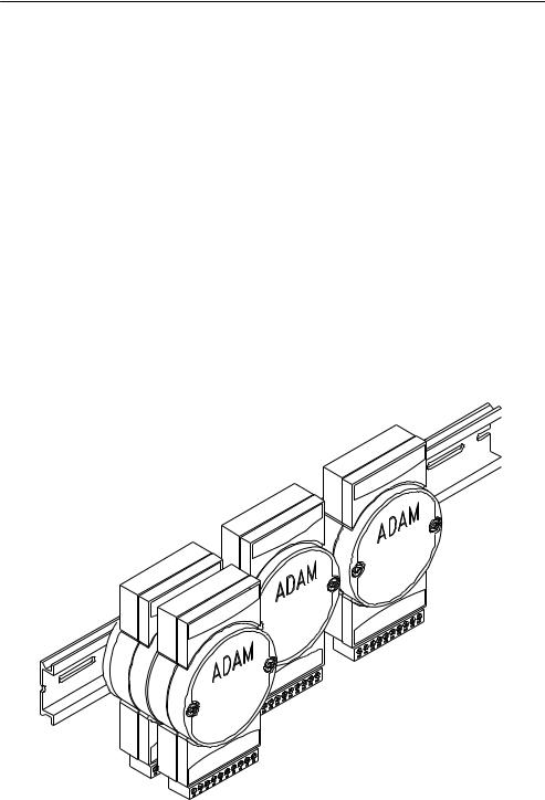
Panel/DIN Rail mounting
Chapter 1 Introduction 1-3

Introduction
ADAM modules can be mounted on any panels, brackets, or DIN rails. They can also be stacked together.
The RS-485 network, together with screw-terminal plug connectors, allows for system expansion, reconfiguration, and repair without disturbing field wiring.
Protection against the environment
Since all the configurations are controlled by software, the protection provided by the packaging is very important. The plastic outer shell enhances resistance against corrosive materials, moistures and vibrations. ADAM modules’ low power requirements help them to operate in temperatures from 0 to 70 , and in humidity from 0 to 95%
(non-condensing). They are compactly built using automated SMT technology. Therefore, they can be implemented in water-tight and explosion-proof industrial enclosures.
1.2Applications
•Remote data acquisition
•Process monitoring
•Industrial process control
•Energy management
•Supervisory control
•Security systems
•Laboratory automation
•Building automation
•Product testing
•Direct digital control
1-4 ADAM 4000 Series User’s Manual
Installation Guideline |
2 |

Installation Guideline
This chapter provides guidelines to what is needed to set up and install an ADAM network. A quick hookup scheme is provided that lets you configure modules before they are installed in a network. To help you connect ADAM modules with sensor inputs, several wiring examples are provided. At last, you will find a programming example using the ADAM command set at the end of this chapter.
Be sure to plan the layout and configuration of your network carefully before you start. Guidelines regarding layout are given in Appendix E: RS-485 Network.
2.1 System Requirements to set up an ADAM network
The following list gives an overview of what is needed to setup, install and configure an ADAM environment.
•ADAM modules
•A host computer, such as an IBM PC/AT compatible, that can output ASCII characters with a RS-232C or RS-485 port.
•Power supply for the ADAM modules (+10 to +30 VDC )
•ADAM Series Utility software
•ADAM Isolated RS-232/RS-485 Converter (optional)
•RS-232/RS-485 ADAM Repeater (optional)
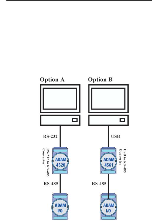
Host computer
Any computer or terminal that can output in ASCII format over either RS-232 or RS-485 can be connected as the host computer. When only RS-232 is available, an ADAM RS-232/RS-485 Converter is required to transform the host signals to the correct RS-485 protocol. The converter also provides opto-isolation and transformer-based isolation to protect your equipment.
2-2 ADAM 4000 Series User’s Manual

Chapter 2
Power supply
For the ease of use in industrial environments, the ADAM modules are designed to accept industry standard +24 VDC, unregulated power.
Operation is guaranteed when using any power supply between +10 and +30 VDC . Power ripples must be limited to 5 V peak to peak while the
voltage in all cases must be maintained between +10 and +30 VDC . All
power supply specifications are referenced at module connector. When modules are powered remotely, the effects of DC voltage drops must be considered.
All modules use on-board switching regulators to sustain good efficiency over the 10 to 30 V input range; therefore, we can assume that the actual drawn current is inversely proportional to the DC voltage. The following example shows how to calculate the required current that a power supply should provide.
Assume that a +24 VDC is used for five ADAM-4011 Analog Input
Modules, and the distance between modules and power supply is not significant enough to cause a DC voltage drop. One ADAM-4011 module consumes a maximum of 1.2 Watts (W). The total required power will equal to 5 x 1.2=6 W. A power supply of +24 VDC should
therefore be able to supply a minimal current of 6 / 24=0.25 Amps.
Small systems may be powered by using wall-mounted modular power supplies. Also, when modules operate in long communication lines (>500 feet), it is often more reliable to obtain power locally through modular power supplies. These inexpensive units can be easily obtained from any electronic retail stores.
The power cables should be selected according to the length of the power lines and the number of modules connected. When implementing a network with long cables, the use of thicker wire is more suitable due to the limitation of DC voltage drop. Furthermore, long wires can also cause interference with communication wires.
Chapter 2 installation Guideline 2-3
Installation Guideline
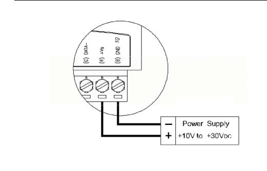
Figure 2-1 Power Supply Connections
We advise the following standard colors (as indicated on the modules) for each power line:
+Vs |
(R) |
Red |
GND |
(B) |
Black |
Communication Wiring
We recommend the use of shielded-twisted-pair cable in the ADAM network for reducing interference purpose, but the cable has to comply with the EIA RS-485 standard. Furthermore, only one set of twistedpair cable is required for transmitting Data. We advise the following standard colors (as indicated on the modules) for each the communication line:
DATA+ |
(Y) |
Yellow |
DATA- |
(G) |
Green |
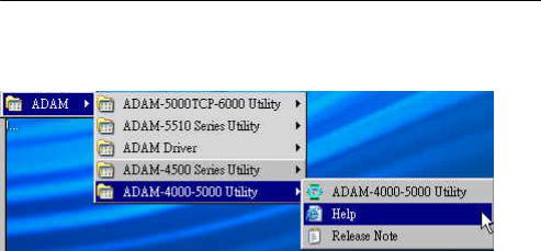
ADAM Utility Software
A menu-driven utility program is provided for ADAM module configuration, monitoring and, calibration. It also includes a terminal emulation program that lets you communicate through the ADAM command set. (See Appendix D, Utility Software and online help)
2-4 ADAM 4000 Series User’s Manual
Chapter 2
Notice: User can refer our help file to see more details for explanation of Utility operation.
ADAM Communication Speed
In ADAM series, the baud rate can be configured from 1200 bps to 38.4 Kbps. However, the baud rate of all modules in an RS-485 network must be the same.
ADAM Isolated RS-232/RS485 Converter (optional): ADAM-452x
When the host computer or terminal only has a RS-232 port, an ADAM Isolated RS-232/RS-485 Converter is required. Since this module is not addressable by the host, the baud rate must be reset using a switch inside the module. The factory default setting is 9600 baud.
ADAM Repeater (optional): ADAM-451x
When communication lines exceed 4000 ft (1200 meter) or more than 32 ADAM modules are connected, a repeater should be implemented. In a network, up to eight Repeater modules can be connected allowing connection up to 255 ADAM modules. As with the Converter module, the Repeater module is not addressable by the host and the baud rate must be reset by changing the switch inside the module. The factory default setting is 9600 baud.
Chapter 2 installation Guideline 2-5
Installation Guideline
2.2 Basic configuration and hook-up
Before placing a module in an existing network, the module should be configured. Though all modules are initially configured at the factory, it is recommended to check if the baud rate is set correctly beforehand.
Default Factory Settings
Baud rate: 9600 Bit/sec.
Address: 01 (hexadecimal)
The basic hook-up for module configuration is shown below.
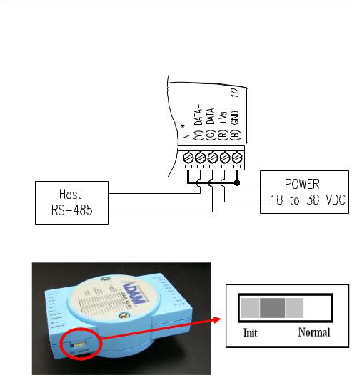
Figure 2-2 Basic Hook-up of ADAM Module to Host Switches
2-6 ADAM 4000 Series User’s Manual

Chapter 2
The following items are required to configure a module: an ADAM converter module, a personal computer with RS-232 port (baud rate set to 9600) and the ADAM utility software.
Configuration with the ADAM Utility Software
The easiest way to configure the ADAM module is by using the ADAM utility software. It is a user friendly structured menu program that will guide you through every step of the configuration. (See Appendix D, Utility Software)
Changing the protocol from ADAM ASCII to Modbus
Some ADAM-4000 modules support both ADAM ASCII and Modbus protocols, and the factory default setting of these modules is ADAM ASCII protocol. If you would like to configure the modules to Modbus protocol, please refer to Appendix H which describes how to change the protocol in ADAM utility.
Configuration with the ADAM command set
ADAM modules can also be configured by issuing direct commands through a terminal emulation program that is part of the ADAM utility software. The following example will guide you through the setup of an analog input module. Assume an ADAM-4011 Analog Input module still has its default settings (baud rate 9600 and address 01h), and you are being requested to send its default settings before any reconfiguration is made.
NOTICE: An analog input module requires a maximum of 7 seconds to perform auto calibration and ranging after reboot or start up. During this time span, the module can not be addressed to perform any other actions.
Example:
Make sure that the module is properly connected and turn on all the connected devices. Then, start the terminal emulation program, and type in the following command:
$012(cr)
The command above requests the module with address 01 to send its configuration status
!01050600
Chapter 2 installation Guideline 2-7

Installation Guideline
Module at address 01 responds that it is configured for an input range of +/-2.5 V, baud rate of 9600, integration time of 50 ms (60 Hz). The code also shows engineering units and no checksum checking or generation.
To change the configuration setting of the analog input module, the following command is issued:
%01070F0600(cr)
% = change configuration
01 = target module at address 00 to:
07 = change address to 07 hexadecimal
0F = set input range to Type K thermocouple
06 = set baud rate to 9600
00 = set integration time to 50 ms (60 Hz) disable checksum
set data format to engineering units
(Please refer to Chapter 4, a full description of Command set syntax for an analog input module)
When the module received the configuration command, it will respond with its new address as shown below:
!07(cr)
Before giving more commands to the module, please wait for 7 seconds to let the new configuration settings to take effect.
NOTICE: All reconfiguration except for changing baud rate and checksum values can be done dynamically, and the modules are not required to reset. However, all the connected devices are required to reset by turning power off and on after the baud rate or checksum values are changed. The baud rate or checksum values should be the same for all the connected devices after the reconfiguration. See the next page for a strategy in changing baud rate and checksum of the network.
2-8 ADAM 4000 Series User’s Manual

Chapter 2
2.3 Baud rate and Checksum
ADAM modules contain EEPROMs to store configuration information and calibration constants. The EEPROM replaces the conventional array of switches and pots that are originally used for specifying baud rate, input and output range… etc.
Since there is no visual indication of a module’s configuration status, it is impossible to know the baud rate, address and other settings just by looking at it. It might not be possible to establish communications with a module whose baud rate and address are unknown. To overcome this problem, most modules have an input terminal labeled INIT*. Booting the module while connecting the INIT* terminal with the module’s GND terminal forces the configuration into a known state called the INIT* state. Besides, some newer modules have INIT switch which you can set “Init” or “Normal” (See Figure 2.4). If you set the switch to “Init”, then it becomes INIT* state.
INIT* state defaults:
Baud rate: 9600
Address: 00h
Checksum: disabled
Forcing the module in INIT* state does not change any parameters in the module’s EEPROM. When the module is in the INIT* state with its INIT* and GND terminals shorted, all configuration settings can be changed, and the module will respond to all other commands normally.
Changing Baud rate and Checksum
Baud rate and checksum settings have several things in common:
•They should be the same for all modules and host computer.
•Their settings can only be changed by putting a module in the INIT* state.
•Changed settings can only take effect after a module is rebooted
To alter baud rate or checksum settings, you must perform the following steps:
Chapter 2 installation Guideline 2-9
Installation Guideline
•Power on all components except the ADAM Module.
•Power the ADAM module on while shorting the INIT* and GND terminals (See Figure 2-3) or set the INIT switch to “Init” (See Figure 2-4)
Figure 2-3 Grounding the INIT* Terminal
Figure 2-4 Set INIT switch to “Init”
•Configure the checksum status and/or the baud rate.
•Switch the power OFF to the ADAM Module.
•Remove the grounding of the INIT* terminal and turn on the module, or set the INIT switch to “Normal”.
•Check the settings (If the baud rate has changed, the settings on the host computer should be changed accordingly).
2-10 ADAM 4000 Series User’s Manual
Chapter 2
2.4 Multiple Module Hookup
The Figure below is an example of how ADAM modules are connected in a multiple module network:
Figure 2-5 Multi-module Connection
Chapter 2 installation Guideline 2-11
Installation Guideline
2.5 Programming Example
The following example is a simple program written in Visual Basic 6.0 that demonstrates how to get temperature reading which is stored in the address of 01H from ADAM-4011 module.
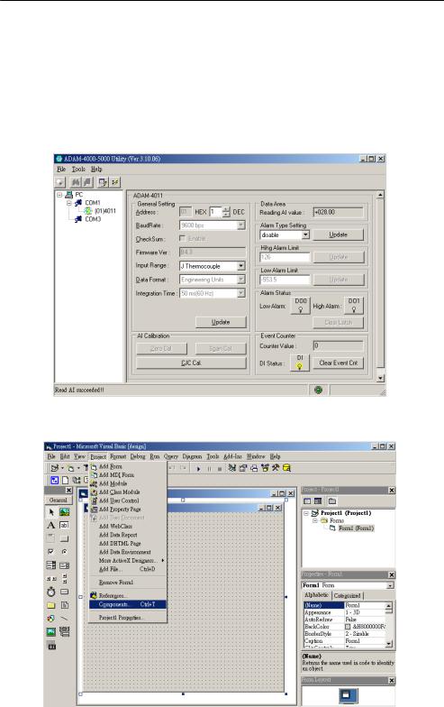
Step 1. Using ADAM Utility to check the settings as the following below: “Address = 01H”, “Baud rate = 9600” and “Checksum = Disabled”.
Step 2. Run VB 6.0 and add a control via “Project\Component”.
2-12 ADAM 4000 Series User’s Manual

Chapter 2
Step 3. Select “Microsoft Comm Control”
Step 4. Add the Comm Control on the form.
Chapter 2 installation Guideline 2-13
Installation Guideline
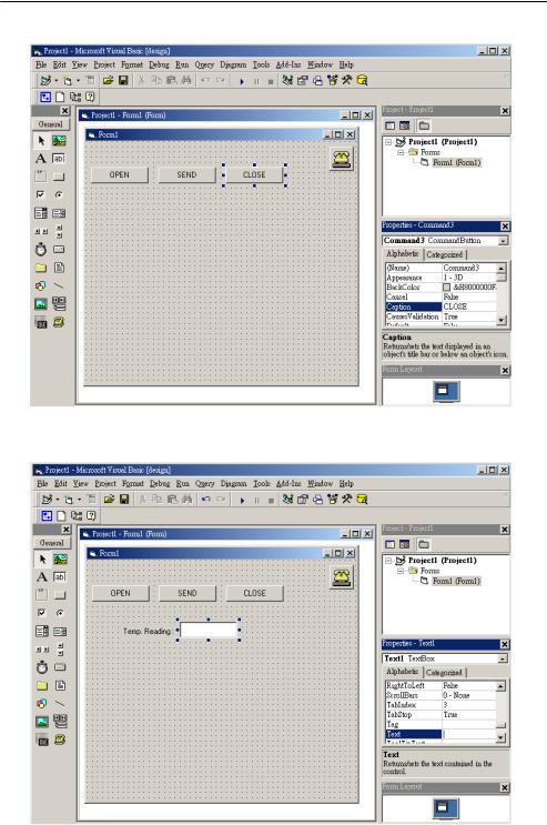
Step 5. Add three Command Buttons on the form as shown below
Step 6. Add one Label and one Text on the form as shown below.
2-14 ADAM 4000 Series User’s Manual
Chapter 2
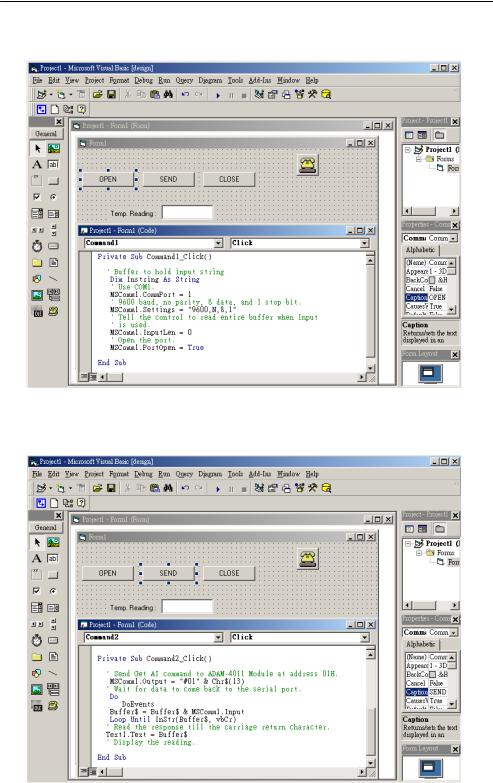
Step 7. Click OPEN Button and type in the following codes. The source codes are listed at the end of this section.
Step 8. Click SEND Button and type in the following codes. The source codes are listed at the end of this section.
Chapter 2 installation Guideline 2-15
Installation Guideline
Step 9. Click CLOSE Button and type in the following codes. The source codes are listed at the end of this section.
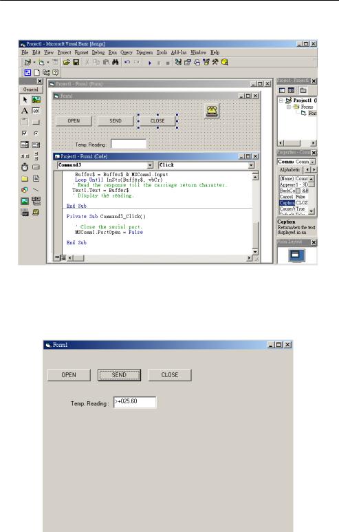
Step 10. Run the Project → Click OPEN to open COM1 → Click SEND to send the Get Temperature Reading Command. Now, you will find the reading the same as the displayed format shown below.
2-16 ADAM 4000 Series User’s Manual

Chapter 2
Program Source Codes:
OPEN Command Button:
Private Sub Command1_Click()
' Buffer to hold input string
Dim Instring As String
'Use COM1. MSComm1.CommPort = 1
'9600 baud, no parity, 8 data, and 1 stop bit. MSComm1.Settings = "9600,N,8,1"
'Tell the control to read entire buffer when Input
'is used.
MSComm1.InputLen = 0 ' Open the port.
MSComm1.PortOpen = True End Sub
SEND Command Button:
Private Sub Command2_Click()
'Send Get AI command to ADAM-4011 Module at address 01H. MSComm1.Output = "#01" & Chr$(13)
'Wait for data to come back to the serial port.
Do
DoEvents
Buffer$ = Buffer$ & MSComm1.Input
Loop Until InStr(Buffer$, vbCr)
'Read the response till the carriage return character. Text1.Text = Buffer$
'Display the reading.
End Sub
CLOSE Command Button
Private Sub Command3_Click()
' Close the serial port.
MSComm1.PortOpen = False
End Sub
Chapter 2 installation Guideline 2-17
I/O Modules |
3 |

I/O Modules
3.0 The common specification of ADAM-4000 I/O Series
Communication:
zRS-485 (2-wire) to host
zSpeeds: 1200, 2400, 4800, 9600, 19200, 38400, 57600, 115200 bps (ADAM-4080, ADAM-4080D only support up to 38400 bps)
zMax. communication distance: 4000 feet (1.2 km)
zPower and communication LED indicator
zASCII command/response protocol
zCommunication error checking with checksum
zAsynchronous data format: 1 start bit, 8 data bits, 1 stop bit, no parity (N, 8, 1)
zUp to 256 multidrop modules per serial port
zOnline module insertion and removal
zTransient suppression on RS-485 communication lines
Power Requirement:
zUnregulated +10 ~ +30 VDC
zProtected against power reversal
Mechanical: |
|
z Case |
ABS+PC with captive mounting hardware |
zPlug-in screw Accepts 0.5 mm2 to 2.5 mm2, Terminal block #14 ~22 or #14~28 AWG
Environment |
|
|
|
z |
EMI |
Meets FCC Class A or CE |
|
z |
Operating Temperature |
-10 |
~ 70° C (14 ~ 158° F) |
z |
Storage Temperature |
-25 |
~ 85° C (-13 ~ 185° F) |
z |
Humidity |
5 ~ 95%, non-condensing |
|
3-2 ADAM 4000 Series User’s Manual

Chapter 3
3.1 ADAM-4011/4011D Thermocouple Input Modules
The ADAM-4011/4011D Thermocouple Input Modules use a microprocessor-controlled integrating A/D converter to convert sensor voltage, current or thermocouple signal into digital data. The digital data is then translated into either two’s complement hexadecimal format or percentage of full-scale range (FSR) according to the module’s configuration. When prompted by the host computer, the data is sent through a standard RS-485 interface.
The ADAM-4011/4011D Thermocouple Input Modules offer signal conditioning, A/D conversion, ranging, and RS-485 digital communication functions. They protect your equipment from power surges at the ground terminal by providing opto-isolation of the A/D input and transformer based isolation up to 3000 VDC. (ADAM-4011
has transformer-based isolation up to 500 VDC)
Open Thermocouple Detection and Input Surge Protection (ADAM-4011D only)
The ADAM-4011D provides an open thermocouple detection function. Users can use a simple command to detect whether the thermocouple is opened or closed. The module also provides surge protection on its input channel. Internal high-speed transient suppressor on its input channel protects the module from dangerous spikes and voltages.
Front Panel LED Indicator (ADAM-4011D only)
The 4½ digits LED display on the back of the ADAM-4011D lets you monitor the process readings right at their source. The module displays readings in a wide variety of formats as well as high-low alarm messages. The ADAM-4011D offers flexibility, easy installation, and direct availability of process data. For critical process monitoring, this module is the ideal choice.
Digital Input/Output
The ADAM-4011/4011D Thermocouple Input Modules also contain two digital outputs and one digital input. Outputs are open-collector transistor switches that may be controlled by the host computer. They can control solid-state relays, which may be used to control heaters, pumps, and other electrical powered equipment. The digital inputs may be read by the host computer and used to sense the state of a remote digital signal.
Chapter 3 I/O Modules 3-3
 Loading...