


 Loading...
User Manual
AIMB-766
Socket LGA 775Core 2 Quad / Intel Core 2 Duo processor / Intel Pentium Dual Core / Celeron 1333 MHz FSB Industrial ATX Motherboard with PCIe/DDR2/ Dual GbE

Copyright
The documentation and the software included with this product are copyrighted 2008 by Advantech Co., Ltd. All rights are reserved. Advantech Co., Ltd. reserves the right to make improvements in the products described in this manual at any time without notice. No part of this manual may be reproduced, copied, translated or transmitted in any form or by any means without the prior written permission of Advantech Co., Ltd. Information provided in this manual is intended to be accurate and reliable. However, Advantech Co., Ltd. assumes no responsibility for its use, nor for any infringements of the rights of third parties, which may result from its use.
Acknowledgements
AWARD is a trademark of Phoenix Technologies Ltd.
IBM and PC are trademarks of International Business Machines Corporation.
Intel® Core 2 Quad, Pentium Dual Core and Celeron are trademarks of Intel Corporation.
WinBond is a trademark of Winbond Corporation.
All other product names or trademarks are properties of their respective owners.
Part No. 2006076600 |
Edition 1 |
Printed in China |
August 2008 |
AIMB-766 User Manual |
ii |

A Message to the Customer
Advantech Customer Services
Each and every Advantech product is built to the most exacting specifications to ensure reliable performance in the harsh and demanding conditions typical of industrial environments. Whether your new Advantech equipment is destined for the laboratory or the factory floor, you can be assured that your product will provide the reliability and ease of operation for which the name Advantech has come to be known.
Your satisfaction is our primary concern. Here is a guide to Advantech’s customer services. To ensure you get the full benefit of our services, please follow the instructions below carefully.
Technical Support
We want you to get the maximum performance from your products. So if you run into technical difficulties, we are here to help. For the most frequently asked questions, you can easily find answers in your product documentation. These answers are normally a lot more detailed than the ones we can give over the phone.
So please consult this manual first. If you still cannot find the answer, gather all the information or questions that apply to your problem, and with the product close at hand, call your dealer. Our dealers are well trained and ready to give you the support you need to get the most from your Advantech products. In fact, most problems reported are minor and are able to be easily solved over the phone.
In addition, free technical support is available from Advantech engineers every business day. We are always ready to give advice on application requirements or specific information on the installation and operation of any of our products.
iii |
AIMB-766 User Manual |

Declaration of Conformity
FCC
This device complies with the requirements in part 15 of the FCC rules: Operation is subject to the following two conditions:
!This device may not cause harmful interference
!This device must accept any interference received, including interference that may cause undesired operation.
This equipment has been tested and found to comply with the limits for a Class A digital device, pursuant to Part 15 of the FCC Rules. These limits are designed to provide reasonable protection against harmful interference when the equipment is operated in a commercial environment. This equipment generates, uses, and can radiate radio frequency energy and, if not installed and used in accordance with the instruction manual, may cause harmful interference to radio communications. Operation of this device in a residential area is likely to cause harmful interference in which case the user will be required to correct the interference at his/her own expense. The user is advised that any equipment changes or modifications not expressly approved by the party responsible for compliance would void the compliance to FCC regulations and therefore, the user's authority to operate the equipment.
Caution! There is a danger of a new battery exploding if it is incorrectly installed. Do not attempt to recharge, force open, or heat the battery. Replace the battery only with the same or equivalent type recommended by the manufacturer. Discard used batteries according to the manufacturer's instructions.
AIMB-766 User Manual |
iv |

Memory Compatibility
Brand |
Size |
Speed |
Type |
ECC Vendor PN |
Advantech PN |
Memory |
||
|
512 MB |
DDR2 |
|
|
|
96D2- |
ELPIDA E5108AG- |
|
|
DDR2 |
N |
78.91G66.420 |
512M533NN- |
||||
|
|
533 |
|
|
|
AP |
5C-E (64x8) |
|
|
|
|
|
|
|
|
||
|
1 GB |
DDR2 |
DDR2 |
N |
78.01G66.420 |
96D2- |
ELPIDA |
|
|
E5108AGBG-6E-E |
|||||||
Apacer |
533 |
1G533NN-AP |
||||||
|
|
|
|
(64x8) |
||||
(RoHS) |
|
|
|
|
|
|
||
1 GB |
DDR2 |
DDR2 |
N |
78.01G91.404 |
NA |
SEC 746 ZCE7 |
||
|
||||||||
|
800 |
K4T51083QE |
||||||
|
|
|
|
|
|
|||
|
1 GB |
DDR2 |
|
|
|
|
ELPIDA |
|
|
DDR2 |
N |
78.01G92.420 |
NA |
E5108AGBG-6E-E |
|||
|
667 |
|||||||
|
|
|
|
|
|
(64x8) |
||
|
|
|
|
|
|
|
||
|
|
|
|
|
|
96D2- |
infineon |
|
|
|
DDR2 |
|
|
|
HYB18T512160AF3 |
||
|
256 MB |
DDR2 |
N |
TS32MLQ64V5M |
256M533NN- |
|||
|
533 |
.7 3VV21710 |
||||||
|
|
|
|
|
|
TR |
(32x16) |
|
|
|
|
|
|
|
|
||
|
|
DDR2 |
|
|
|
96D2- |
SEC K4T51083QC |
|
|
512 MB |
DDR2 |
N |
TS64MLQ64V5J |
512M533NN- |
|||
|
|
533 |
|
|
|
TR1 |
ZCD5 (64X8) |
|
|
|
|
|
|
|
|
||
|
|
DDR2 |
|
|
|
96D2- |
SEC K4T51083QC |
|
|
1 GB |
DDR2 |
N |
TS128MLQ64V5J |
1G533NN- |
|||
|
533 |
ZCD5 (64X8) |
||||||
Transcend |
|
|
|
|
TR1 |
|||
|
|
|
|
|
|
|||
(RoHS) |
|
DDR2 |
|
|
|
96D2- |
SEC K4T51083QC |
|
|
512 MB |
DDR2 |
N |
TS64MLQ64V6J |
512M667NN- |
|||
|
|
667 |
|
|
|
TR |
ZCE6 (64x8) |
|
|
|
|
|
|
|
|
||
|
|
DDR2 |
|
|
|
96D2- |
Micron |
|
|
512 MB |
DDR2 |
N |
TS64MLQ64V6J |
512M667NN- |
5XB32D9DCL |
||
|
|
667 |
|
|
|
TR |
(64x8) |
|
|
|
|
|
|
|
|||
|
1 GB |
DDR2 |
DDR2 |
N |
TS2QNJ23450-6S |
96D2- |
SEC K4T51083QE |
|
|
667 |
1G667NN-TR |
ZCE6 (64x8) |
|||||
|
2 GB |
DDR2 |
DDR2 |
N |
TS256MLQ64V6U NA |
Micron 7HE12 |
||
|
667 |
D9HNL (128x8) |
||||||
|
|
|
|
|
|
|||
|
|
DDR2 |
|
|
|
|
ProMOS |
|
|
1 GB |
DDR2 |
N |
TS128MLQ64V8J |
NA |
V59C1512804QBF2 |
||
|
800 |
|||||||
Transcend |
|
|
|
|
|
5 (64x8) |
||
|
|
|
|
|
|
|||
(RoHS) |
|
DDR2 |
|
|
|
|
SAMSUNG |
|
|
2 GB |
DDR2 |
N |
TS256MLQ64V6U |
NA |
K4T1G084QA- |
||
|
667 |
|||||||
|
|
|
|
|
|
ZCE6 (128x8) |
||
|
|
|
|
|
|
|
||
|
|
DDR2 |
|
|
|
|
ELPIDA |
|
|
1 GB |
DDR2 |
N |
NA |
NA |
E5108AGBG-6E-E |
||
|
667 |
|||||||
|
|
|
|
|
|
(64x8) |
||
|
|
|
|
|
|
|
||
|
|
DDR2 |
|
|
|
|
ELPIDA |
|
|
2 GB |
DDR2 |
N |
NA |
NA |
E5108AGBG-6E-E |
||
|
667 |
|||||||
|
|
|
|
|
|
(128x8) |
||
DSL |
|
|
|
|
|
|
||
|
DDR2 |
|
|
|
|
ELPIDA |
||
|
|
|
|
|
|
|||
|
1 GB |
DDR2 |
N |
NA |
NA |
E5108AHSE-8E-E |
||
|
800 |
|||||||
|
|
|
|
|
|
(64x8) |
||
|
|
|
|
|
|
|
||
|
|
DDR2 |
|
|
|
|
ELPIDA |
|
|
2 GB |
DDR2 |
N |
NA |
NA |
E1108ACBG-8E-E |
||
|
800 |
|||||||
|
|
|
|
|
|
(128x8) |
||
|
|
|
|
|
|
|
||
|
2 GB |
DDR2 |
DDR2 |
N |
KVR667D2N5/2G |
NA |
Micron 7KE12 |
|
|
667 |
D9HNL (128x8) |
||||||
Kingston |
|
|
|
|
|
|||
|
|
|
|
|
|
ELPIDA |
||
(RoHS) |
|
DDR2 |
|
|
|
|
||
1 GB |
DDR2 |
N |
KVR800D2N5/1G |
NA |
E5108AHSE-8E-E |
|||
|
800 |
|||||||
|
|
|
|
|
|
(64x8) |
||
|
|
|
|
|
|
|
||
v |
AIMB-766 User Manual |

Samsung 1 GB |
DDR2 |
DDR2 N |
|
800 |
|||
|
|
AIMB-766 Feature Comparison
LAN/Model |
AIMB-766G2-00A1E |
AIMB-766VG-00A1E |
Chipset |
Q35+ICH9DO |
Q35+ICH9 |
SATA |
6 |
4 |
SW RAID |
0, 1, 5, 10 |
None |
LAN1 |
Intel 82556DM |
Intel 82556DM |
LAN2 |
Intel 82573L |
None |
AMT 3.0 |
Yes |
No |
Product Warranty (2 years)
Advantech warrants to you, the original purchaser, that each of its products will be free from defects in materials and workmanship for two years from the date of purchase.
This warranty does not apply to any products which have been repaired or altered by persons other than repair personnel authorized by Advantech, or which have been subject to misuse, abuse, accident or improper installation. Advantech assumes no liability under the terms of this warranty as a consequence of such events.
Because of Advantech’s high quality-control standards and rigorous testing, most of our customers never need to use our repair service. If an Advantech product is defective, it will be repaired or replaced at no charge during the warranty period. For out- of-warranty repairs, you will be billed according to the cost of replacement materials, service time and freight. Please consult your dealer for more details.
If you think you have a defective product, follow these steps:
1.Collect all the information about the problem encountered. (For example, CPU speed, Advantech products used, other hardware and software used, etc.) Note anything abnormal and list any onscreen messages you get when the problem occurs.
2.Call your dealer and describe the problem. Please have your manual, product, and any helpful information readily available.
3.If your product is diagnosed as defective, obtain an RMA (return merchandize authorization) number from your dealer. This allows us to process your return more quickly.
4.Carefully pack the defective product, a fully-completed Repair and Replacement Order Card and a photocopy proof of purchase date (such as your sales receipt) in a shippable container. A product returned without proof of the purchase date is not eligible for warranty service.
5.Write the RMA number visibly on the outside of the package and ship it prepaid to your dealer.
AIMB-766 User Manual |
vi |

Initial Inspection
Before you begin installing your motherboard, please make sure that the following materials have been shipped:
!AIMB-766 Intel Core 2 Quad/ Core 2 Duo/ Pentium Dual Core/ Celeron processor based industrial motherboard
!1 AIMB-766 startup manual
!1 Driver CD (user's manual is included)
!1 FDD cable
!1 Ultra ATA 66/100 HDD cable
!2 Serial ATA HDD data cable
!2 Serial ATA HDD power cable
!2 COM port cable kit (2 to 2, 1 to 1)
!1 I/O port bracket
!1 jumper package
!1 warranty card
If any of these items are missing or damaged, contact your distributor or sales representative immediately. We have carefully inspected the AIMB-766 mechanically and electrically before shipment. It should be free of marks and scratches and in perfect working order upon receipt. As you unpack the AIMB-766, check it for signs of shipping damage. (For example, damaged box, scratches, dents, etc.) If it is damaged or it fails to meet the specifications, notify our service department or your local sales representative immediately. Also notify the carrier. Retain the shipping carton and packing material for inspection by the carrier. After inspection, we will make arrangements to repair or replace the unit.
vii |
AIMB-766 User Manual |

AIMB-766 User Manual |
viii |

Contents
Chapter |
1 |
Hardware Configuration...................... |
1 |
||
|
1.1 |
Introduction ............................................................................................... |
|
2 |
|
|
1.2 |
Features .................................................................................................... |
|
3 |
|
|
1.3 |
Specifications ............................................................................................ |
|
4 |
|
|
|
1.3.1 |
System .......................................................................................... |
|
4 |
|
|
1.3.2 |
Memory ......................................................................................... |
|
4 |
|
|
1.3.3 |
Input/Output .................................................................................. |
5 |
|
|
|
1.3.4 |
Ethernet LAN ................................................................................ |
5 |
|
|
|
1.3.5 |
Industrial Features ........................................................................ |
5 |
|
|
|
1.3.6 Mechanical and Environmental Specifications.............................. |
5 |
||
|
1.4 |
Jumpers and Connectors .......................................................................... |
6 |
||
|
|
|
Table 1.1: Jumper list .................................................................. |
6 |
|
|
|
|
Table 1.2: Connectors ................................................................. |
6 |
|
|
1.5 |
Board Layout: Jumper and Connector Locations...................................... |
8 |
||
|
|
|
Figure 1.1 |
Jumper and Connector Locations............................... |
8 |
|
|
|
Figure 1.2 |
I/O connectors ............................................................ |
8 |
|
1.6 |
AIMB-766 Block Diagram.......................................................................... |
9 |
||
|
|
|
Figure 1.3 |
AIMB-766 Block Diagram ........................................... |
9 |
|
1.7 |
Safety Precautions |
.................................................................................. |
10 |
|
|
1.8 |
Jumper Settings ...................................................................................... |
|
11 |
|
|
|
1.8.1 How to set jumpers ..................................................................... |
11 |
||
|
|
1.8.2 |
CMOS clear (CMOS1) ................................................................ |
11 |
|
|
|
|
Table 1.3: CMOS1..................................................................... |
11 |
|
|
|
1.8.3 Watchdog timer output (JWDT1) ................................................ |
12 |
||
|
|
|
Table 1.4: Watchdog timer output (JWDT1) .............................. |
12 |
|
|
|
|
Table 1.5: ATX/AT mode selector (PSON1).............................. |
12 |
|
|
|
|
Table 1.6: COM2 RS-232/422/485 mode selector (JSETCOM2).. |
||
|
1.9 |
System Memory |
12 |
13 |
|
|
|
||||
|
|
1.9.1 CPU FSB and memory speed..................................................... |
13 |
||
|
1.10 |
Memory Installation Procedures.............................................................. |
13 |
||
|
1.11 |
Cache Memory........................................................................................ |
|
13 |
|
|
1.12 |
Processor Installation.............................................................................. |
14 |
||
|
1.13 |
PCI Bus Routing Table............................................................................ |
15 |
||
Chapter 2 |
Connecting Peripherals .................... |
17 |
2.1 |
Introduction ............................................................................................. |
18 |
2.2 |
Primary (IDE1) IDE Connector................................................................ |
18 |
2.3 |
Floppy Drive Connector (FDD1).............................................................. |
19 |
2.4 |
Parallel Port (LPT1)................................................................................. |
20 |
2.5USB Ports (LAN1_USB12, LAN2_USB34, USB56, USB78, USB910 &
|
USB1112)................................................................................................ |
|
21 |
2.6 |
VGA Connector (VGA1) .......................................................................... |
|
22 |
2.7 |
Serial Ports (COM1, COM2, COM3 & COM4) ........................................ |
|
23 |
2.8 |
PS/2 Keyboard and Mouse Connector (KBMS1) .................................... |
|
24 |
2.9 |
External Keyboard & Mouse (KBMS2).................................................... |
|
25 |
2.10 |
CPU Fan Connector (CPUFAN1)............................................................ |
|
26 |
2.11 |
System FAN Connector (SYSFAN1 and SYSFAN2) .............................. |
27 |
|
2.12 |
Front Panel Connectors (JFP1, JFP2 & JFP3) ....................................... |
|
28 |
|
2.12.1 Power LED and Keyboard Lock (JFP3) ...................................... |
|
28 |
|
Table 2.1: PS/2 or ATX power supply LED status.................... |
28 |
|
|
2.12.2 External Speaker (JFP2 pins 1, 3, 5 & 7).................................... |
|
28 |
|
2.12.3 HDD LED Connector (JFP2 pins 2 & 4)...................................... |
|
29 |
|
3 |
AIMB-766 User Manual |
|

|
2.12.4 ATX Soft Power Switch (JFP1 pins 1 & 2).................................. |
29 |
|
2.12.5 Reset Connector (JFP1 pins 3 & 4) ............................................ |
29 |
2.13 |
Line Out, Mic In Connector (AUDIO1) .................................................... |
30 |
2.14 |
8-pin Alarm Board Connector (VOLT1)................................................... |
31 |
2.15 |
Case Open Connector (JCASE1) ........................................................... |
32 |
2.16 |
Front Panel LAN Indicator Connector (LAN_LED1)................................ |
33 |
|
Table 2.2: Front Panel LAN Indicator Connector ...................... |
33 |
2.17Serial ATA Interface (SATA1, SATA2, SATA3, SATA4, SATA5 & SATA6) 34
2.18 |
PCI Slots (PCI 1 ~ PCI 4)........................................................................ |
35 |
2.19 |
PCIe x16 Expansion Slot (PCIEX16_1) .................................................. |
36 |
2.20 |
PCIEX1_1 ............................................................................................... |
37 |
2.21 |
PCIEX1_2 ............................................................................................... |
38 |
2.22 |
Auxiliary 4-pin power connector (ATX1) ................................................. |
39 |
2.23 |
TPM connector (20-1 pin TPM_SLOT) ................................................... |
39 |
2.24 |
SPI Flash connector(SPI_CN1) .............................................................. |
39 |
Chapter |
3 |
BIOS Operation ................................. |
41 |
|||
|
|
|
Figure |
3.1 |
Setup program initial screen..................................... |
42 |
|
3.1 |
Entering Setup ........................................................................................ |
|
43 |
||
|
|
|
Figure |
3.2 |
Press Del to run Setup ............................................. |
43 |
|
3.2 |
Main Setup.............................................................................................. |
|
|
44 |
|
|
|
|
Figure |
3.3 |
Main setup screen .................................................... |
44 |
|
|
3.2.1 System time / System date ......................................................... |
44 |
|||
|
3.3 |
Advanced BIOS Features Setup............................................................. |
45 |
|||
|
|
|
Figure |
3.4 |
Advanced BIOS features setup screen .................... |
45 |
|
|
3.3.1 |
CPU Configuration...................................................................... |
46 |
||
|
|
|
Figure |
3.5 |
CPU Configuration Setting ....................................... |
46 |
|
|
3.3.2 |
IDE Configuration ....................................................................... |
47 |
||
|
|
|
Figure |
3.6 |
IDE Configuration ..................................................... |
47 |
|
|
3.3.3 |
Super I/O Configuration .............................................................. |
48 |
||
|
|
|
Figure |
3.7 |
Super I/O Configuration............................................ |
48 |
|
|
3.3.4 |
Hardware Health Configuration .................................................. |
49 |
||
|
|
|
Figure |
3.8 |
Hardware health configuration ................................. |
49 |
|
3.4 |
ACPI Settings.......................................................................................... |
|
|
50 |
|
|
|
|
Figure |
3.9 |
ACPI Settings ........................................................... |
50 |
|
|
|
Figure 3.10General ACPI Configuration..................................... |
50 |
||
|
|
3.4.1 |
General ACPI Configuration ....................................................... |
51 |
||
|
|
|
Figure 3.11Advanced ACPI Configuration.................................. |
51 |
||
|
|
3.4.2 |
Advanced ACPI Configuration .................................................... |
51 |
||
|
|
|
Figure 3.12South Bridge ACPI Configuration............................. |
52 |
||
|
|
3.4.3 South Bridge ACPI Configuration ............................................... |
52 |
|||
|
3.5 |
APM Configuration.................................................................................. |
|
53 |
||
|
|
|
Figure 3.13APM Configuration ................................................... |
53 |
||
|
|
|
Figure 3.14Configure Remote Access type and parameters...... |
54 |
||
|
3.6 |
Configure Remote Access Type and parameters .................................. |
54 |
|||
|
3.7 |
Trusted Computing |
................................................................................. |
55 |
||
|
|
|
Figure 3.15Trusted Computing................................................... |
55 |
||
|
3.8 |
Advanced PCI/PnP Settings ................................................................... |
56 |
|||
|
|
|
Figure 3.16PCI/PNP Setup (top) ................................................ |
56 |
||
|
|
3.8.1 |
Clear NVRAM ............................................................................. |
56 |
||
|
|
3.8.2 Plug and Play O/S ...................................................................... |
56 |
|||
|
|
3.8.3 |
PCI Latency Timer ...................................................................... |
56 |
||
|
3.9 |
Boot Settings........................................................................................... |
|
|
57 |
|
|
|
|
Figure 3.17Boot Setup Utility...................................................... |
57 |
||
|
|
|
Figure 3.18Boot Setting Configuration ....................................... |
57 |
||
|
|
3.9.1 |
Boot settings Configuration......................................................... |
58 |
||
|
3.10 |
Security Setup......................................................................................... |
|
|
58 |
|
AIMB-766 User Manual |
4 |
|
|
|
Figure 3.19Password Configuration ........................................... |
58 |
|
3.11 |
Advanced Chipset Settings ..................................................................... |
59 |
|
|
|
|
Figure 3.20Advanced Chipset Settings ...................................... |
59 |
|
|
|
Figure 3.21 North Bridge Configuration ...................................... |
59 |
|
|
3.11.1 |
North Bridge Chipset Configuration ............................................ |
60 |
|
|
|
Figure 3.22Video function configuration ..................................... |
60 |
|
|
|
Figure 3.23South Bridge Configuration ...................................... |
61 |
|
|
3.11.2 |
South Bridge Chipset Configuration............................................ |
61 |
|
|
|
Figure 3.24South Bridge Chipset Configuration ......................... |
62 |
|
|
3.11.3 |
ME Subsystem Configuration ..................................................... |
62 |
|
3.12 |
Exit Option............................................................................................... |
63 |
|
|
|
|
Figure 3.25Exit Option ................................................................ |
63 |
|
|
3.12.1 |
Save Changes and Exit .............................................................. |
63 |
|
|
3.12.2 |
Discard Changes and Exit .......................................................... |
63 |
|
|
3.12.3 |
Load Optimal Defaults ................................................................ |
64 |
|
|
3.12.4 |
Load Fail-Safe Defaults .............................................................. |
64 |
Chapter |
4 |
Chipset Software Installation Utility 65 |
||
|
4.1 |
Before you begin ..................................................................................... |
66 |
|
|
4.2 |
Introduction ............................................................................................. |
66 |
|
|
4.3 |
Windows XP Driver Setup....................................................................... |
67 |
|
Chapter |
5 |
VGA Setup.......................................... |
69 |
|
|
5.1 |
Introduction ............................................................................................. |
70 |
|
|
5.2 |
Windows Vista/XP/2000 Driver Setup..................................................... |
70 |
|
Chapter |
6 |
LAN Configuration............................. |
71 |
|
|
6.1 |
Introduction ............................................................................................. |
72 |
|
|
6.2 |
Features .................................................................................................. |
72 |
|
|
6.3 |
Installation ............................................................................................... |
72 |
|
|
6.4 |
Win XP Driver Setup (LAN)..................................................................... |
73 |
|
Chapter |
7 |
AMT Setup.......................................... |
75 |
|
|
7.1 |
Intel AMT Overview................................................................................. |
76 |
|
|
7.2 |
Windows XP Intel ME (Management Engine) Interface Setup................ |
76 |
|
|
7.3 |
Windows XP AMT ME Driver Setup........................................................ |
79 |
|
Appendix A |
Programming the Watchdog Timer..83 |
|||
|
A.1 |
Watchdog timer overview........................................................................ |
84 |
|
|
A.2 |
Programming the Watchdog Timer ......................................................... |
84 |
|
|
|
|
Table A.1: Watchdog timer registers.......................................... |
86 |
|
|
A.2.1 |
Example Programs ..................................................................... |
86 |
Appendix B |
I/O Pin Assignments.......................... |
91 |
||
|
B.1 |
IDE Hard Drive Connector (IDE1) ........................................................... |
92 |
|
|
|
|
Table B.1: IDE hard drive connector (IDE1) .............................. |
92 |
|
B.2 |
Floppy Drive Connector (FDD1).............................................................. |
93 |
|
|
|
|
Table B.2: Floppy drive connector (FDD1) ................................ |
93 |
|
B.3 |
Parallel Port (LPT1)................................................................................. |
94 |
|
5 |
AIMB-766 User Manual |

|
Table B.3: Parallel Port (LPT1).................................................. |
94 |
B.4 |
USB Header (USB56, USB78, USB910 & USB1112) ............................ |
94 |
|
Table B.4: USB Header (USB56,USB78,USB910).................... |
94 |
B.5 |
VGA Connector (VGA1).......................................................................... |
95 |
|
Table B.5: VGA Connector (VGA1) ........................................... |
95 |
B.6 |
RS-232 Interface (COM1, COM2, COM3 & COM4) ............................... |
95 |
|
Table B.6: RS-232 Interface (COM1) ........................................ |
95 |
B.7 |
PS/2 Keyboard and Mouse Connector (KBMS1).................................... |
96 |
|
Table B.7: Keyboard and Mouse Connector (KBMS1) .............. |
96 |
B.8 |
External Keyboard Connector (KBMS2) ................................................. |
96 |
|
Table B.8: External Keyboard Connector (KBMS2)................... |
96 |
B.9 |
Infrared (IR) connector (JIR1) ................................................................. |
97 |
|
Table B.9: Infrared Connector (JIR1)......................................... |
97 |
B.10 |
CPU/System Fan Power Connector (SYSFAN1/SYSFAN2) .................. |
97 |
|
Table B.10:Fan Power Connector (SYSFAN1/CHAFAN1)......... |
97 |
B.11 |
Power LED and Keyboard Lock (JFP3) .................................................. |
97 |
|
Table B.11:Power LED and Keyboard Lock (JFP3) ................... |
97 |
B.12 |
External Speaker Connector (JFP2) ....................................................... |
98 |
|
Table B.12:External Speaker Connector (JFP2) ........................ |
98 |
B.13 |
Reset Connector (JFP1) ......................................................................... |
98 |
|
Table B.13:Reset Connector (JFP1)........................................... |
98 |
B.14 |
HDD LED Connector (JFP2)................................................................... |
98 |
|
Table B.14:HDD LED Connector (JFP2) .................................... |
98 |
B.15 |
ATX Soft Power Switch (JFP1) ............................................................... |
99 |
|
Table B.15:ATX Soft Power Switch (JFP1) ................................ |
99 |
B.16 |
H/W Monitor Alarm (JOBS1)................................................................... |
99 |
|
Table B.16:H/W Monitor Alarm (JOBS1) .................................... |
99 |
B.17 |
SM Bus Connector (JFP2) ...................................................................... |
99 |
|
Table B.17:SM Bus Connector (JFP2) ....................................... |
99 |
B.18 |
USB/LAN ports (LAN1_USB12 and LAN2_USB34) ............................. |
100 |
|
Table B.18:USB Port ................................................................ |
100 |
|
Table B.19:Giga LAN 10/100/1000 Base-T RJ-45 port ............ |
100 |
B.19 |
Line Out, Mic IN Connector (AUDIO1).................................................. |
100 |
B.20 |
Audio Input from CD-ROM (CDIN1)...................................................... |
101 |
|
Table B.20:Audio Input from CD-ROM ..................................... |
101 |
B.21 |
Front Panel Audio Connector (FP AUDIO; FAUDIO1).......................... |
101 |
|
Table B.21:Audio Connector (FP AUDIO; FAUDIO1)............... |
101 |
B.22 |
8-pin Alarm Board Connector (VOLT1)................................................. |
101 |
|
Table B.22:8-pin Alarm Board Connector (VOLT1) .................. |
101 |
B.23 |
Case Open Connector (JCASE1) ......................................................... |
102 |
|
Table B.23:Case Open Connector (JCASE1)........................... |
102 |
B.24 |
Front Panel LAN LED Connector (LAN_LED1) .................................... |
102 |
|
Table B.24:LAN LED Connector (LANLED1) ........................... |
102 |
B.25 |
SPI_CN1: SPI fresh card pin connector................................................ |
103 |
|
Table B.25:SPI_CN1:SPI fresh card pin connector .................. |
103 |
B.26 |
TPM_SLOT1: TPM module connector.................................................. |
103 |
|
Table B.26:TPM_SLOT1:TPM module connector .................... |
103 |
B.27 |
System I/O Ports................................................................................... |
104 |
|
Table B.27:System I/O ports..................................................... |
104 |
B.28 |
DMA Channel Assignments .................................................................. |
104 |
|
Table B.28:DMA channel assignments..................................... |
104 |
B.29 |
Interrupt Assignments ........................................................................... |
105 |
|
Table B.29:Interrupt assignments............................................. |
105 |
B.30 |
1st MB Memory Map............................................................................. |
105 |
|
Table B.30:1st MB memory map .............................................. |
105 |
AIMB-766 User Manual |
6 |

Chapter 1
1Hardware Configuration

1.1 Introduction
The AIMB-766 is the most advanced Intel Q35 product for industrial applications that require high-performance computing. The motherboard supports Intel Core 2 Duo / Core 2 Quad / Pentium Dual Core / Celeron processors with 800/1066/1333 MHz front side bus and DDR2 667/ 800 MHz memory up to 8 GB.
The AIMB-766 incorporates the Intel Q35 chipset to offer cost-effective integrated graphics. The Q35 chipset uses the Intel Extreme Graphics architecture (GMA 3100) to maximize VGA performance and share up to 256 MB of system memory. When higher graphics performance is needed, the AIMB-766 provides a mainstream PCIe x16 expansion slot for add-on graphic cards. In addition, the AIMB-766 has a single/ dual Gigabit Ethernet LAN via a dedicated PCIe x1 bus, which offers bandwidth of up to 500 MB/s, eliminating network bottlenecks. High reliability and outstanding performance make the AIMB-766 the idea platform for industrial networking applications.
By using the Intel ICH9 DO chipset, the AIMB-766 offers four 32-bit, 33 MHz PCI slots; two PCIe x1 slot, one PCIe x16 slot and a variety of features such as 6 onboard SATA II interfaces (bandwidth = 300 MB/s) with software for RAID 0, 1, 10 and 5; 12 USB 2.0 connections; 1 ATA 100/66/33 port; and HD Audio. These powerful I/O capabilities ensure even more reliable data storage capabilities and high-speed I/O peripheral connectivity.
The AIMB-766 also adopts Advantech’s unique patented “Sleep Mode Control Circuit” for AT Power Mode.
With all the excellent features and outstanding performance, the AIMB-766 is definitely the ideal platform for today’s industrial applications.
AIMB-766 User Manual |
2 |

1.2Features
!PCIe architecture: The Intel Q35 and ICH9 DO (or ICH9) PCIe chipset supports 1 PCIe x16 slot, 2 PCIe x1 slot and a PCIe x1 link for the Gigabit LAN.
!High Performance I/O Capability: Dual/single Gigabit LAN via PCIe x1 bus, 4 PCI 32-bit/33MHz PCI slots, 6 SATA2 connectors and 12 USB 2.0 ports.
!Standard ATX form factor with industrial features: AIMB-766 provides industrial features like long product life, reliable operation under wide temperature range, watchdog timer, CMOS backup functions, etc.
!BIOS CMOS backup and restore: When BIOS CMOS setup has been completed, data in the CMOS RAM is automatically backed up to the Flash ROM. This is particularly useful in harsh environments which may cause setup data loss such as battery failure. Upon such an error occurring, the BIOS will check the data, and automatically restore the original data for booting.
!Automatically power on after power failure: It is often required to have an unattended system come back to operation when power resumes after a power failure. Advantech’s industrial motherboard allows users to set the system to power on automatically without pushing the power on button.
!Active Management Technology 3.0: The hardware and firmware base solution (ICH9 DO only, for AIMB-766G2-00A1E sku only) is powered by the system auxiliary power plane to remotely monitor networked systems. Intel AMT stores hardware and software information in non-volatile memory. Built-in management provides out-of-band management capabilities, allowing remote discoverery and repair of systems after OS failures or when a system is powered down. Alert and event logging features detect problems and quickly reduce downtime, pro-actively blocking incoming threats, containing infected clients before they impact the network, and proactively notifying the user when critical software agents are removed.
Configuration Hardware 1 Chapter
3 |
AIMB-766 User Manual |

1.3 Specifications
1.3.1System
!CPU: Intel LGA 775 Core 2 Quad, Core 2 Duo, Pentium Dual Core, Celeron up to 2.83/3.16/2.2/2.0 GHz, FSB 800/1066/1333 MHz. Advantech also certifies several optional high-performance CPU coolers for high-speed CPUs in 2U chassis or in high-temperature environments
Note! Advantech certifies two LGA775 CPU cooler solutions. Both coolers are capable of keeping the temperature of 95W-thermal-spec CPUs within specification under environmental temperatures of 55°C without a chassis or 40°C with a chassis.
1750000334: LGA 775 CPU Cooler for 4U, 5U, and 7U chassis.
1750001661: LGA 775 CPU Cooler for 2U chassis and wall-mount chassis.
!L2 Cache: CPU has one of the following built-in full-speed L2 caches
12/6 MB for Core 2 Quad 4/2 MB for Core 2 Duo
1 MB for Pentium® Dual Core
512 KB for Celeron®
!BIOS: AMI 32 Mbit SPI
!System Chipset: Intel Q35 with ICH9DO
!SATA hard disk drive interface: Six on-board SATA2 connectors support Advanced Host controller interface (AHCI) technology and have data transmission rates up to 300 MB/s
!One on-board IDE connector: Supports PIO mode 4 (16.67 MB/s) and ATA 33/66/100 (33/66/100 MB/s) BIOS enabled/disabled.
!Floppy disk drive interface: Supports one floppy disk drive, 5 1/4" (360 KB and 1.2 MB) or 3 1/2" (720 KB, 1.44 MB). BIOS enable/disable
1.3.2Memory
!RAM: Up to 8 GB in four 240-pin DIMM sockets. Supports dual-channel DDR2 667/800 SDRAM
Note! 1. A 64-bit OS may not fully detect 8 GB of RAM when 8 GB is installed.
2.A 32-bit OS may not fully detect 4 GB of RAM when 4 GB is installed.
AIMB-766 User Manual |
4 |

1.3.3Input/Output
!PCIe slots: 1 PCIe x16 expansion slot and 2 PCIe x1 expansion slot
!PCI Bus: 4 PCI slots, 32-bit, 33 MHz PCI 2.2 compliant
!Enhanced parallel port: Configured to LPT1, LPT2, LPT3, or disabled. Standard DB-25 female connector provided. Supports EPP/SPP/ECP
!Serial ports: Four serial ports, one of RS-232/422/485 and three of RS-232. DB-9 connector located in rear panel is RS-232
!Keyboard and PS/2 mouse connector: Two 6-pin mini-DIN connectors are located on the mounting bracket for easy connection to a PS/2 keyboard and mouse
!USB port: Supports up to 12 USB 2.0 ports with transmission rates up to 480 Mbps
1.3.4Ethernet LAN
!Supports single/dual 10/100/1000Base-T Ethernet port(s) via PCIe x1 bus which provides a 500 MB/s data transmission rate.
!Interface: 10/100/1000Base-T
!Controller: LAN1: Intel 82766DM, LAN2: Intel 82573L
1.3.5Industrial Features
!Watchdog timer: Can generate a system reset or NC. The watchdog timer is programmable, with each unit equal to one second or one minute (255 levels)
1.3.6Mechanical and Environmental Specifications
!Operating temperature: 0 ~ 55°C (32 ~ 131° F, Depending on CPU)
!Storage temperature: -20 ~ 70° C (-4 ~ 158° F)
!Humidity: 5 ~ 95% non-condensing
!Power supply voltage: +3.3 V, +5 V, ±12 V, 5 Vsb
!Power consumption:
Maximum: +5 V at 3.58 A, +3.3 V at 2.86 A, +12 V at 3.52 A, +5 Vsb at 0.74 A, -12 V at 0.02 A (Intel Core 2 Quad9300 2.5 GHz (1333 MHz FSB), 4 x 1 GB DDR2 800 SDRAM)
!Board size: 304.8 x 228.6 mm (12" x 9.6")
!Board weight: 0.5 kg (1.68 lb)
Configuration Hardware 1 Chapter
5 |
AIMB-766 User Manual |

1.4 Jumpers and Connectors
Connectors on the AIMB-766 motherboard link it to external devices such as hard disk drives and a keyboard. In addition, the board has a number of jumpers that are used to configure your system for your application.
The tables below list the function of each of the jumpers and connectors. Later sections in this chapter give instructions on setting jumpers. Chapter 2 gives instructions for connecting external devices to your motherboard.
Table 1.1: Jumper list
Label |
Function |
|
|
CMOS1 |
CMOS |
JWDT1 |
Watchdog reset |
PSON1 |
AT(1-2) / ATX(2-3) |
JSETCOM2 |
COM2 RS-232/422/485 jumper setting |
Table 1.2: Connectors
Label |
Function |
|
|
IDE1 |
Primary IDE connector (one channel) |
FDD1 |
FDD connector |
LPT1 |
Parallel port, parallel port x 1, supports SPP/EPP/ECP mode |
LAN1_USB12 |
LAN1 / USB port 1, 2 |
LAN2_USB34 |
LAN2 / USB port 3, 4 |
VGA1 |
VGA connector |
COM1 |
Serial port: COM1; RS-232 (DB-9 connector) |
COM2~4 |
COM2;RS-232/422/485, COM3~COM4;RS-232 |
KBMS1 |
PS/2 keyboard and mouse connector |
KBMS2 |
External keyboard connector (6-pin) |
JIR1 |
Infrared connector |
|
Keyboard lock and power LED |
|
Suspend: fast flash (ATX/AT) |
JFP3 |
System On: on (ATX/AT) |
|
System Off: off (AT) |
|
System Off: slow flash (ATX) |
JFP2 |
External speaker / SATA HDD LED connector / SM Bus connector |
JFP1 |
Power switch / reset connector |
JCASE1 |
Case open |
VOLT1 |
Voltage display |
|
HW monitor |
JOBS1 |
Close: enable OBS alarm |
|
Open: disable OBS alarm |
CPUFAN1 |
CPU fan connector (4-pin) |
SYSFAN1 |
System fan connector (4-pin) |
SYSFAN2 |
System fan connector (4-pin) |
LANLED1 |
LAN1/2 LED extension connector |
AUDIO1 |
Audio connector |
FPAUO1 |
HD audio front panel pin header |
USB56 |
USB port 5, 6 |
AIMB-766 User Manual |
6 |

Table 1.2: Connectors
Label |
Function |
|
|
USB78 |
USB port 7, 8 |
USB910 |
USB port 9, 10 |
USB1112 |
USB port 11,12 |
SATA1 |
Serial ATA1 |
SATA2 |
Serial ATA2 |
SATA3 |
Serial ATA3 |
SATA4 |
Serial ATA4 |
SATA5 |
Serial ATA5 |
SATA6 |
Serial ATA6 |
ATX1 |
ATX 12 V auxiliary power connector (for CPU) |
ATX2 |
ATX 24-pin main power connector (for system) |
PCIEX16_1 |
PCIe x16 slot 1 |
PCIEx1_1/PCIEx1_2 PCIe x 1 slot1, PCIe x 1 slot2 |
|
PCI1 |
PCI slot 1 |
PCI2 |
PCI slot 2 |
PCI3 |
PCI slot 3 |
PCI4 |
PCI slot 4 |
DIMMA1 |
Channel A DIMM1 |
DIMMA2 |
Channel A DIMM2 |
DIMMB1 |
Channel B DIMM1 |
DIMMB2 |
Channel B DIMM2 |
SPI_CN1 |
Update BIOS pin header |
TPM_SLOT1 |
TPM2.0 Module connector |
Configuration Hardware 1 Chapter
7 |
AIMB-766 User Manual |
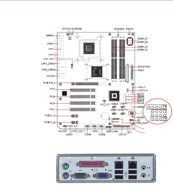
1.5Board Layout: Jumper and Connector Locations
JFP3 |
JFP2 |
JFP1 |
JWDT1
JOBS1
Figure 1.1 Jumper and Connector Locations
Figure 1.2 I/O connectors
AIMB-766 User Manual |
8 |
1.6 AIMB-766 Block Diagram
Figure 1.3 AIMB-766 Block Diagram
Configuration Hardware 1 Chapter
9 |
AIMB-766 User Manual |
1.7 Safety Precautions
Warning! Always completely disconnect the power cord from your chassis whenever you work with the hardware. Do not make connections while the power is on. Sensitive electronic components can be damaged by sudden power surges. Only experienced electronics personnel should open the PC chassis.
Caution! Always ground yourself to remove any static charge before touching the motherboard. Modern electronic devices are very sensitive to static electric charges. As a safety precaution, use a grounding wrist strap at all times. Place all electronic components on a static-dissipative surface or in a static-shielded bag when they are not in the chassis.
Caution! The computer is provided with a battery-powered Real-time Clock circuit. There is a danger of explosion if battery is incorrectly replaced. Replace only with same or equivalent type recommended by the manufacturer. Discard used batteries according to manufacturer’s instructions.
Caution! There is a danger of a new battery exploding if it is incorrectly installed. Do not attempt to recharge, force open, or heat the battery. Replace the battery only with the same or equivalent type recommended by the manufacturer. Discard used batteries according to the manufacturer’s instructions.
AIMB-766 User Manual |
10 |

1.8 Jumper Settings
This section provides instructions on how to configure your motherboard by setting the jumpers. It also includes the motherboard default settings and your options for each jumper.
1.8.1 How to set jumpers
You can configure your motherboard to match the needs of your application by setting the jumpers. A jumper is a metal bridge that closes an electrical circuit. It consists of two metal pins and a small metal clip (often protected by a plastic cover) that slides over the pins to connect them. To “close” (or turn on) a jumper, you connect the pins with the clip. To “open” (or turn off) a jumper, you remove the clip. Sometimes a jumper consists of a set of three pins, labeled 1, 2, and 3. In this case you connect either pins 1 and 2, or 2 and 3. A pair of needle-nose pliers may be useful when setting jumpers.
1.8.2 CMOS clear (CMOS1)
The AIMB-766 motherboard contains a jumper that can erase CMOS data and reset the system BIOS information. Normally this jumper should be set with pins 1-2 closed. If you want to reset the CMOS data, set J1 to 2-3 closed for just a few seconds, and then move the jumper back to 1-2 closed. This procedure will reset the CMOS to its default setting.
Table 1.3: CMOS1
Function Jumper Setting
* Keep CMOS data
1-2 closed
Clear CMOS data
2-3 closed
* default setting
Configuration Hardware 1 Chapter
11 |
AIMB-766 User Manual |
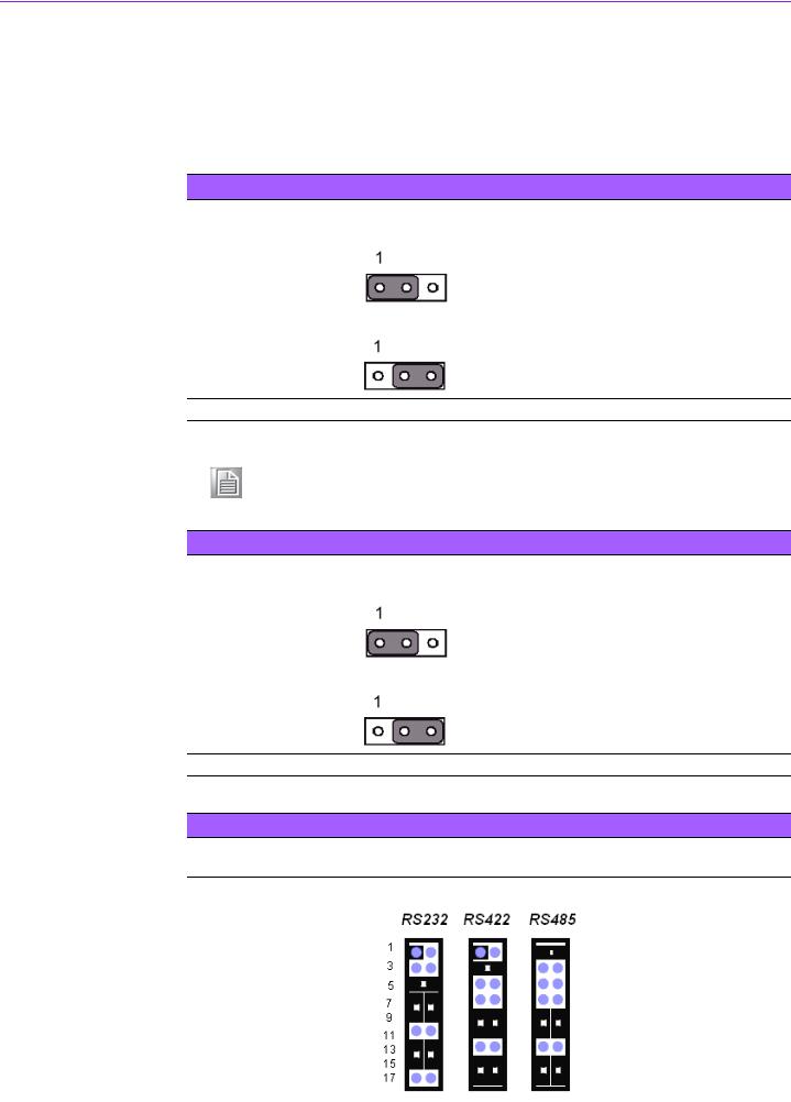
1.8.3 Watchdog timer output (JWDT1)
The AIMB-766 contains a watchdog timer that will reset the CPU. This feature means the AIMB-766 will recover from a software failure or an EMI problem. The JSETCOM2 jumper settings control the outcome of what the computer will do in the event the watchdog timer is tripped.
Table 1.4: Watchdog timer output (JWDT1)
Function |
Jumper Setting |
NC |
1-2 closed |
|
|
|
|
* Reset
2-3 closed
* default setting
Note! The interrupt output of the watchdog timer is a low level signal. It will be held low until the watchdog timer is reset.
Table 1.5: ATX/AT mode selector (PSON1)
Function |
Jumper Setting |
AT Mode |
1-2 closed |
|
|
|
|
* ATX Mode
2-3 closed
* default setting
Table 1.6: COM2 RS-232/422/485 mode selector (JSETCOM2)
Use JSETCOM2 to select the RS-232/422/485 mode for COM2. The default setting is RS232.
AIMB-766 User Manual |
12 |

1.9 System Memory
The AIMB-766 has four sockets for 240-pin dual inline memory modules (DIMMs) in two memory channels.
All these sockets use 1.8 V unbuffered double data rate synchronous DRAMs (DDR SDRAM). They are available in capacities of 256, 512 1024 and 2048 MB. The sockets can be filled in any combination with DIMMs of any size, giving a total memory size between 256 MB and 8 GB.
1.9.1 CPU FSB and memory speed
The AIMB-766 can accept DDR2 SDRAM memory chips without parity. Also note that the AIMB-766 accepts DDR2 667/800 MHz SDRAM, and DDR2 SDRAM. The AIMB766 does not support ECC (error checking and correction).
1.10 Memory Installation Procedures
To install DIMMs, first make sure the two handles of the DIMM socket are in the “open” position. i.e. The handles lean outward. Slowly slide the DIMM module along the plastic guides on both ends of the socket, and then press the DIMM module right down into the socket, until you hear a click. This is when the two handles have automatically locked the memory module into the correct position of the DIMM socket. To remove the memory module, just push both handles outward, and the memory module will be ejected by the mechanism in the socket.
1.11 Cache Memory
The AIMB-766 supports a CPU with one of the following built-in full speed L2 caches: 6 MB for Core 2 Quad
4 MB for Core 2 Duo
1 MB for Pentium® Dual Core
512 KB for Celeron® D
The built-in second-level cache in the processor yields much higher performance than conventional external cache memories.
Configuration Hardware 1 Chapter
13 |
AIMB-766 User Manual |

1.12 Processor Installation
The AIMB-766 is designed for Intel Core 2 Quad, Core 2 Duo, Pentium dual-core, Celeron D processors.
1.Pull the bar besides the CPU socket outward and lift it.
2.Align the triangular marking on the processor with the cut edge of the socket.
AIMB-766 User Manual |
14 |

3.Put back the socket cap and press down the bar to fix it.
1.13 PCI Bus Routing Table
AD |
PCI1 |
PCI2 |
PCI3 |
PCI4 |
|
PCI slot INT |
|
|
|
|
|
31 |
25 |
29 |
28 |
||
|
|||||
|
|
|
|
|
|
A |
B |
D |
D |
A |
|
B |
C |
A |
A |
B |
|
C |
D |
B |
B |
C |
|
D |
A |
C |
C |
D |
Configuration Hardware 1 Chapter
15 |
AIMB-766 User Manual |

AIMB-766 User Manual |
16 |

Chapter 2
2Connecting Peripherals

2.1 Introduction
You can access most of the connectors from the top of the board as it is being installed in the chassis. If you have a number of cards installed, you may need to partially remove a card to make all the connections.
2.2 Primary (IDE1) IDE Connector
You can attach up to one IDE (Integrated Drive Electronics) drive to the AIMB-766’s built-in controller.
Wire number 1 on the cable is red or blue and the other wires are gray. Connect one end to connector IDE1 on the motherboard. Make sure that the red/blue wire corresponds to pin 1 on the connector (in the upper right hand corner).
Connect the hard drive to the other end of the cable. Wire 1 on the cable should also connect to pin 1 on the hard drive connector, which is labeled on the drive circuit board. Check the documentation that came with the drive for more information.
AIMB-766 User Manual |
18 |
Loading...