

Page 1
U
B
1
A
U
U
B
1
A
A
N
T
U
T
T
2 C
3
T
2 C
3 L
4 T
dob e A f t er E ff ec ts H elp
sing H elp | C on t en ts | Inde x
ack
sing H elp
U sing Help
bout online Help
dobe Systems, Inc. provides complete documentation in the Adobe PDF Help system.
The Help system includes information on all the tools, commands, and features for both
Windows and Mac OS. The PDF format is designed for easy navigation online, and support
for third-party screen readers compatible with Windows. The Help can also be printed as a
desktop reference.
avigating in Help
he Help will open in an Acrobat window with the bookmark pane open. If the bookmark
pane is not open choose Window > Bookmarks. You can also navigate using the
navigation bar, the index, or search the document.
At the top and bottom of each page is a navigation bar. Click Using Help to return to this
introduction. Clicking Contents, or Index will take you to that section.
The Next Page and the Previous Page arrows let you move through the pages
sequentially. Click Back to return to the last page you viewed. You can also use the
navigation arrows in the Acrobat toolbar.
sing bookmarks, the table of contents, the index, and Find
he contents of Help are shown as bookmarks in the bookmark pane. To view subtopics,
click the plus sign next to a bookmark. Each bookmark is a hyperlink to the associated
section of the Help document.
To go to the information, click its bookmark. As the information is displayed in the
document pane, its bookmark is highlighted.
You can turn highlighting on or off by selecting the Highlight Current Bookmark option
from the bookmark pane menu.
o find a topic using the table of contents:
1 C lick Contents in the navigation bar at the top or bottom of any page.
lick a topic on the Contents page to move to the first page of that topic.
In the b ookmark pane, expand the topic to see its subtopics.
o find a topic using the index:
1 C lick Index in the navigation bar at the top or bottom of any page.
lick the appropriate letter at the top of the page.
You can also expand the Index bookmark, and click the letter in the bookmark pane.
ocate your entry, and click the page number link to view the information.
o view multiple entries, click Back to return to the same place in the index.
sing H elp | C on t en ts | Inde x
ack
Page 2

U
B
2
A
U
U
B
2 T
2 En
3 T
P
A
dob e A f t er E ff ec ts H elp
sing H elp | C on t en ts | Inde x
o find a topic using the Find command:
1 C hoose Edit > Find.
ter a word or a phrase in the text box, and click OK.
Acrobat will search the document, starting from the current page, and display the first
occurrence of the word or phrase you are searching for.
o find the next occurrence, choose Edit > Find Again.
sing H elp
ack
rinting the Help file
lthough the Help has been optimized for on-screen viewing, you can print pages you
select, or the entire file.
To print, choose Print from the File menu, or click the printer icon in the Acrobat toolbar.
sing H elp | C on t en ts | Inde x
ack
Page 3
U
B
3
A
C on t en ts
U
B
3
C
G
dob e A f t er E ff ec ts H elp
sing H elp | C on t en ts | Inde x
ontents
allery of effects 4
Effects included with After Effects 34
3D Channel effects (Pro only) 35
Adjust effects 39
Audio effects 46
Blur & Sharpen effects 51
Channel effects 55
Distort effects 68
Expression Controls effects 89
ack
Image Control effects 90
Keying effects 101
Matte Tools effects (Pro only) 113
Noise effects 115
Paint effects (Pro only) 123
Perspective effects 138
Render effects 142
Simulation effects 168
Stylize effects 208
Text effects 219
Time effects 228
Transition effects 234
Video effects 241
Legal Notices 243
sing H elp | C on t en ts | Inde x
ack
Page 4
U
B
4
A
G
U
B
4
dob e A f t er E ff ec ts H elp
sing H elp | C on t en ts | Inde x
aller y of eff ec ts
ack
Gal lery of effects
3D C hannel effects
“3D C hannel Extract (Pro only)” on page 35 Or iginal (left), with Texture UV selected, and then used
with the Set Matte effect as a Luminance matte (right)
“Depth Matte (Pro only)” on page 36 Original (left) and with two different depths selected (center
and right)
“Depth of Field (Pro only)” on page 36 Original (left) and with variations of Depth of Field applied
(center and right)
“Fog 3D (Pro only)” on page 37 Original (left), Gradient Layer (center), and with Fog 3D applied
(right)
sing H elp | C on t en ts | Inde x
ack
Page 5
Adobe After Effects Help Gallery of effects
Using Help | Contents | Index Back 5
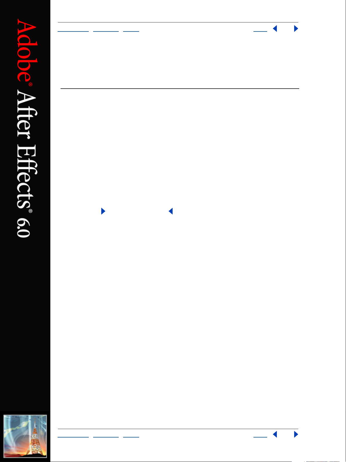
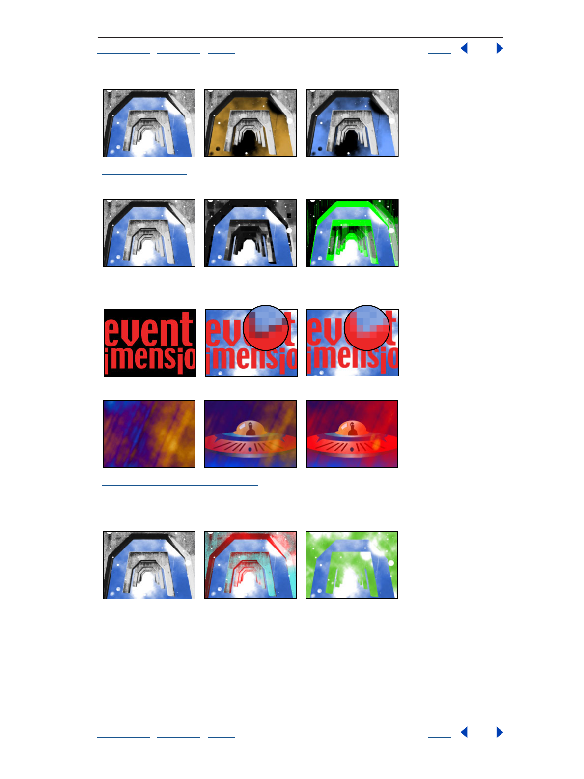
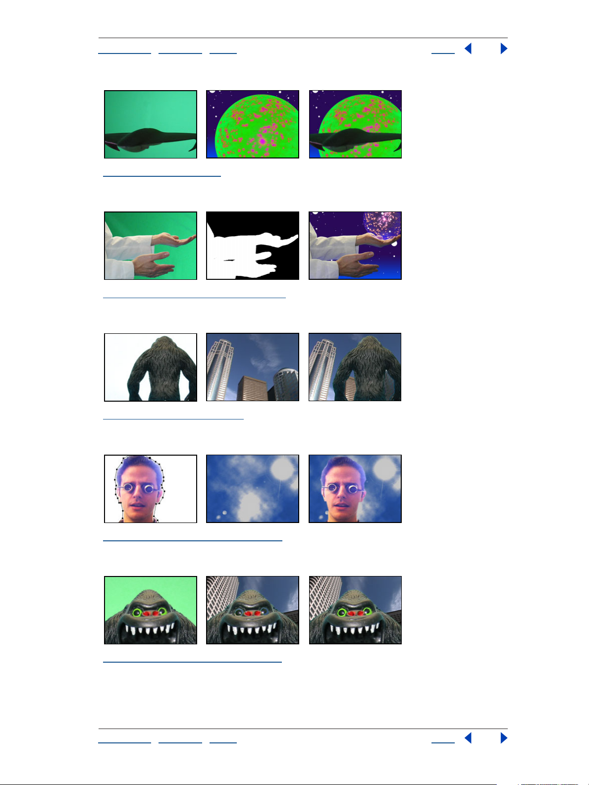
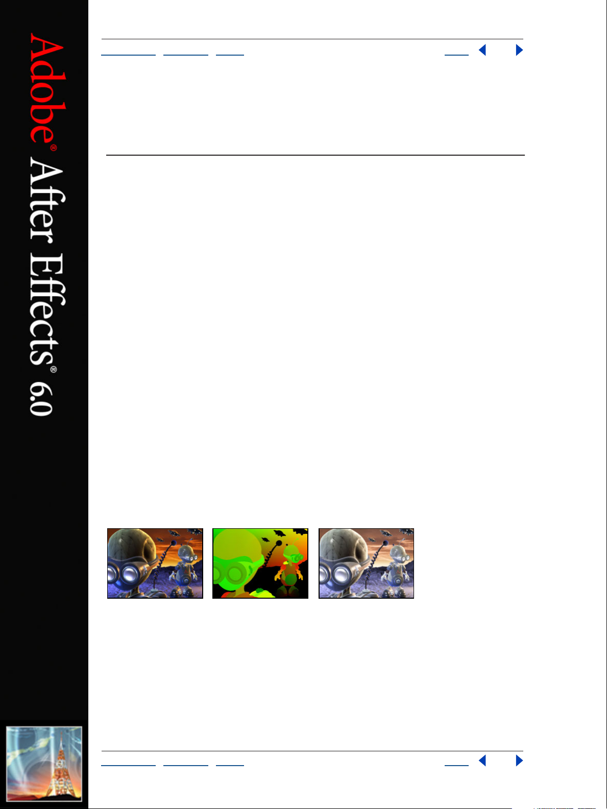
“ID Matte (Pro only)” on page 38 Original (left), with ID Matte applied using the near alien as the
ID Selection (center), and composited over a new background (right)
Adjust effects
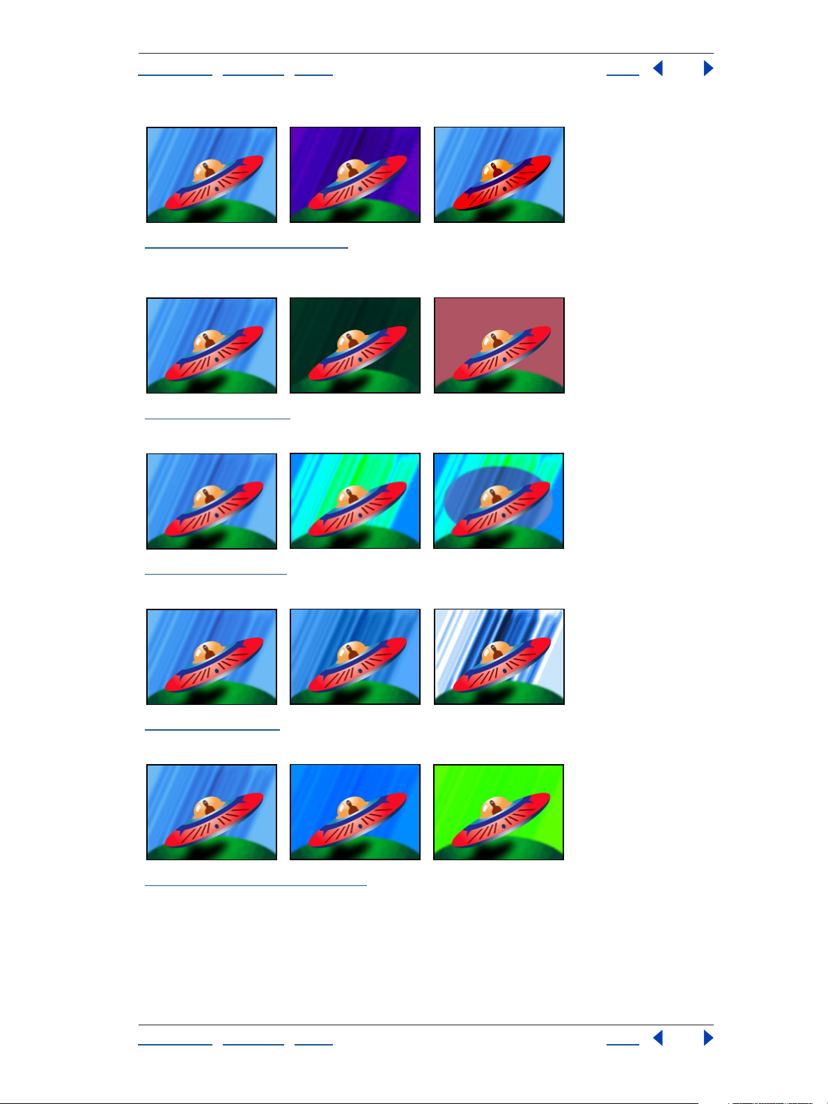
“Brightness & Contrast” on page 39 Original (left) and with variations of Brightness & Contrast
applied (center and right)
“Channel Mixer” on page 39 Original (left) and with variations of Channel Mixer applied (center
and right)
“Color Balance” on page 40 Original (left) and with variations of Color Balance applied (center and
right)
“Curves” on page 41 Original (left) and with variations of Curves applied (center and right)
Using Help | Contents | Index Back 5
Page 6
Adobe After Effects Help Gallery of effects
Using Help | Contents | Index Back 6
“Hue/Saturation” on page 42 Original (left) and with variations of Hue/Saturation applied (center
and right)
“Levels” on page 44 Original (left) and with variations of Levels applied (center and right)
“Levels (Individual Controls)” on page 45 Original (left) and with variations of Levels (Individual
Controls) applied (center and right)
“Posterize” on page 45 Original (left) and with variations of Posterize applied (center and right)
“Threshold” on page 45 Original (left) and with variations of Threshold applied (center and right)
Using Help | Contents | Index Back 6
Page 7
Adobe After Effects Help Gallery of effects
Using Help | Contents | Index Back 7
Blur and Sharpen effects
“Channel Blur” on page 51 Original (left) and with variations of Channel Blur applied (center and
right)
“Compound Blur” on page 51 Original (left), with Compound Blur applied (center), and with
Compound Blur applied and the cloud layer made invisible (right)
“Directional Blur” on page 52 Original (left) and with variations of Directional Blur applied (center
and right)
“Fast Blur” on page 52 Original (left) and with variations of Fast Blur applied (center and right)
“Gaussian Blur” on page 53 Original (left) and with variations of Gaussian Blur applied (center and
right)
Using Help | Contents | Index Back 7
Page 8
Adobe After Effects Help Gallery of effects
Using Help | Contents | Index Back 8
“Radial Blur” on page 53 Original (left) and with variations of Radial Blur applied (center and right)
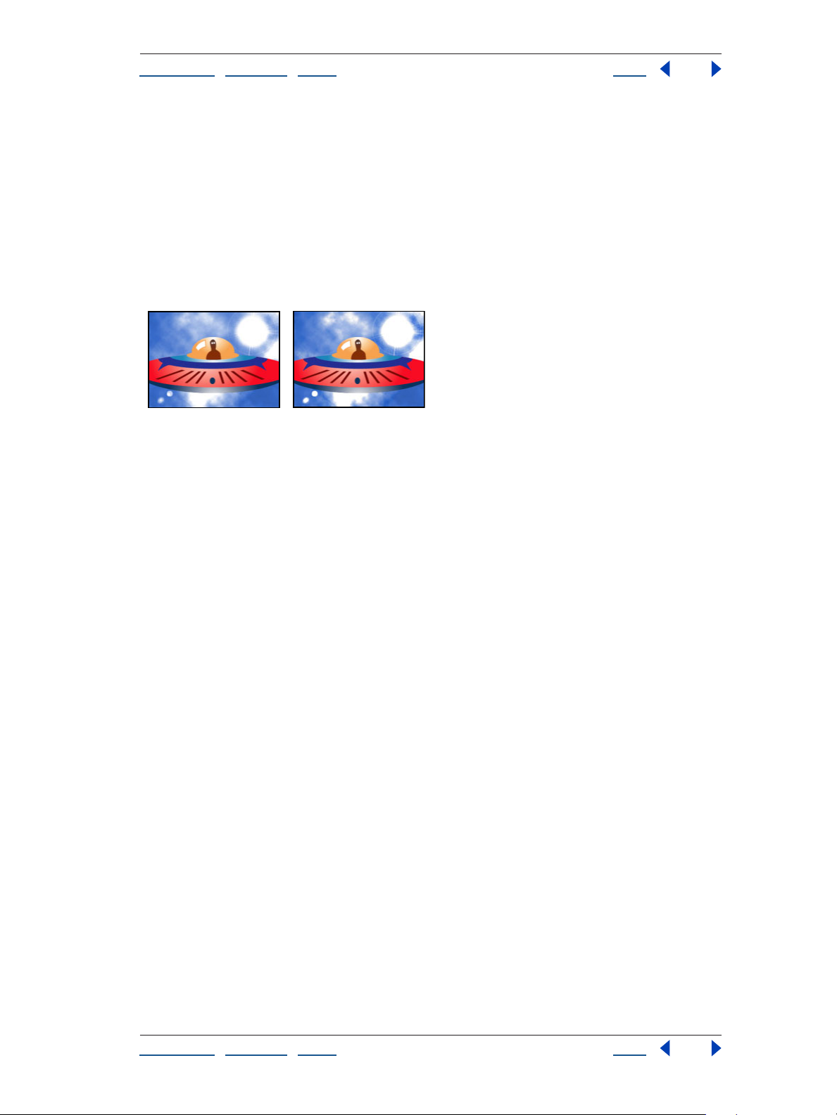
“Sharpen” on page 53 Original (left) and with Sharpen applied (right)
“Unsharp Mask” on page 54 Original (left) and with Unsharp Mask applied (right)
Channel effects
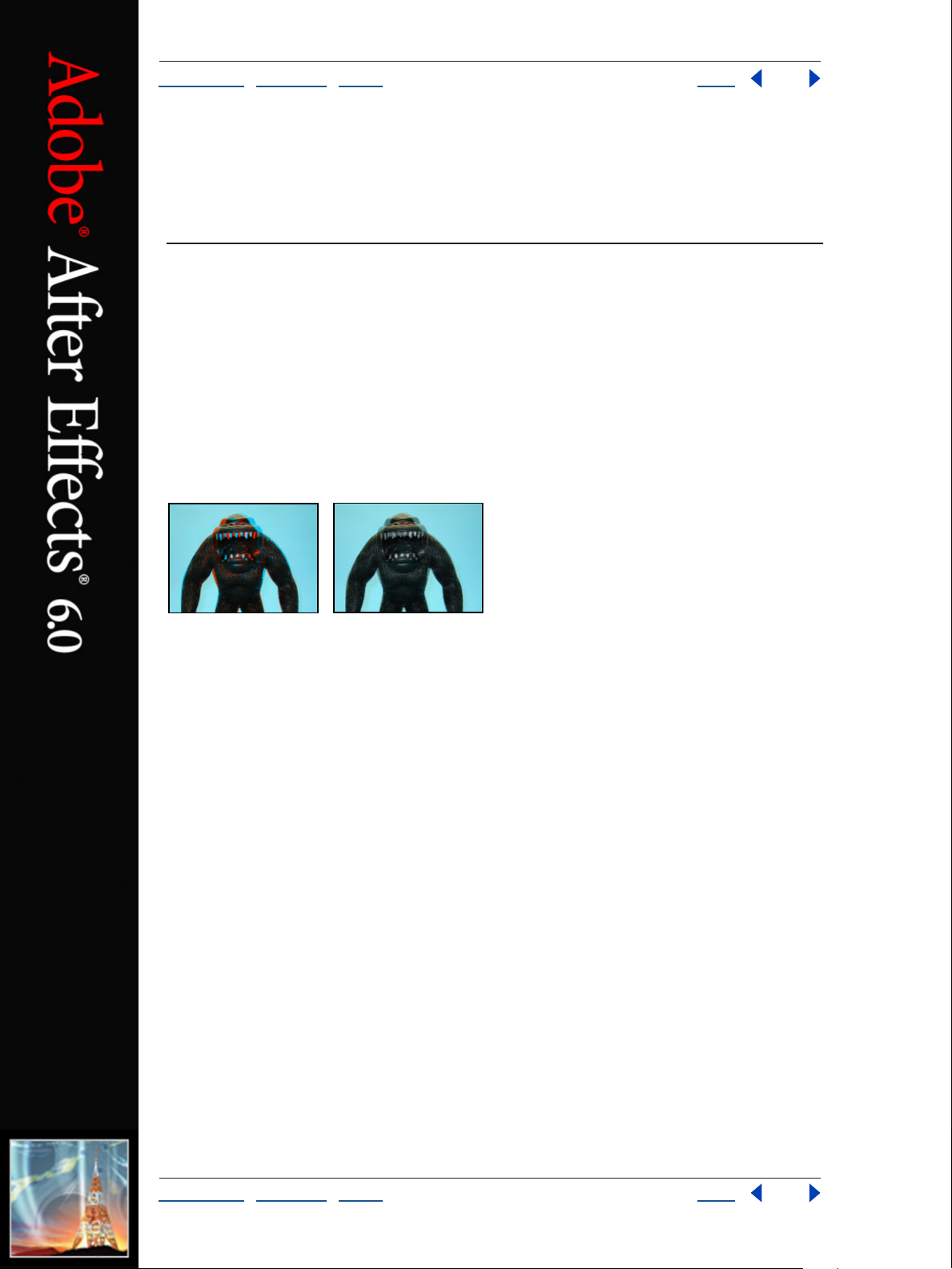
“3D Glasses” on page 55 Two variations of 3D Glasses
“Alpha Levels (Pro only)” on page 57 Original (left) and with variations of Alpha Levels applied
(center and right)
Using Help | Contents | Index Back 8
Page 9
Adobe After Effects Help Gallery of effects
Using Help | Contents | Index Back 9
“Arithmetic” on page 58 Original (left) and with variations of Arithmetic applied (center and right)
“Blend” on page 58 Originals (left and center) and with Blend applied (right)
“Calculations” on page 59 Originals (left and center) and with Calculations applied (right)
“Channel Combiner” on page 60 Original (left) and with variations of Channel Combiner applied
(center and right)
“Compound Arithmetic” on page 62 Originals (left and center) and with Compound Arithmetic
applied (right)
Using Help | Contents | Index Back 9
Page 10
Adobe After Effects Help Gallery of effects
Using Help | Contents | Index Back 10
“Invert” on page 63 Original (left) and with variations of Invert applied (center and right)
“Minimax” on page 64 Original (left) and with variations of Minimax applied (center and right)
“Remove Color Matting” on page 64 Top: Remove Color Matting used to remove a halo (center)
from imported text (left) with the result (right) Bottom: Two source layers combined (left and center)
and Remove Color Matting used to refine the result (right)
“Set Channels” on page 65 Original (left) and with variations of Set Channels applied (center and
right)
Using Help | Contents | Index Back 10
Page 11
Adobe After Effects Help Gallery of effects
Using Help | Contents | Index Back 11
“Set Matte” on page 66 Original (left) and with variations of Set Matte applied (center and right)
“Shift Channels” on page 67 Original (left) and with variations of Shift Channels applied (center
and right)
“Solid Composite” on page 67 Original (left) and with variations of Solid Composite applied (center
and right)
Distort effects
“Bezier Warp (Pro only)” on page 68 Original (left), with Bezier Warp applied and Bezier curve
highlighted (center), and resulting layer (right)
“Bulge (Pro only)” on page 69 Original (left) and with variations of Bulge applied (center and right)
Using Help | Contents | Index Back 11
Page 12
Adobe After Effects Help Gallery of effects
Using Help | Contents | Index Back 12
“Corner Pin (Pro only)” on page 70 Original (left) and with variations of Corner Pin applied (center
and right)
“Displacement Map (Pro only)” on page 70 Original (left), displacement map (center), and with
Displacement Map applied (right)
“Liquify” on page 71 Original (left) and with variations of Liquify applied (center and right)
“Magnify” on page 73 Original (left) and with variations of Magnify applied (center and right)
“Mesh Warp (Pro only)” on page 74 Original (left), warp grid (center), and resulting layer (right)
Using Help | Contents | Index Back 12
Page 13
Adobe After Effects Help Gallery of effects
Using Help | Contents | Index Back 13
“Mirror” on page 75 Original (left) and with variations of Mirror applied (center and right)
“Offset” on page 75 Original (left) and with variations of Offset applied (center and right)
“Optics Compensation (Pro only)” on page 76 Original (left) with Optics Compensation applied to
correct the image (center), and exaggerates lens distortion (right)
“Polar Coordinates” on page 77 Original (left) and with variations of Polar Coordinates applied
(center and right)
“Reshape (Pro only)” on page 78 Original with masks selected (left) and with variations of Reshape
applied (center and right)
Using Help | Contents | Index Back 13
Page 14
Adobe After Effects Help Gallery of effects
Using Help | Contents | Index Back 14
“Ripple” on page 80 Rippling a layer
“Smear” on page 81 Original with masks selected (left) and with variations of Smear applied (center
and right)
“Spherize” on page 83 Original (left) and with variations of Spherize applied (center and right)
“Transform” on page 83 Original (left) and with variations of Transform applied (center and right)
“Turbulent Displace” on page 84 Original (left) and with variations of Turbulent Displace applied
(center and right)
Using Help | Contents | Index Back 14
Page 15
Adobe After Effects Help Gallery of effects
Using Help | Contents | Index Back 15
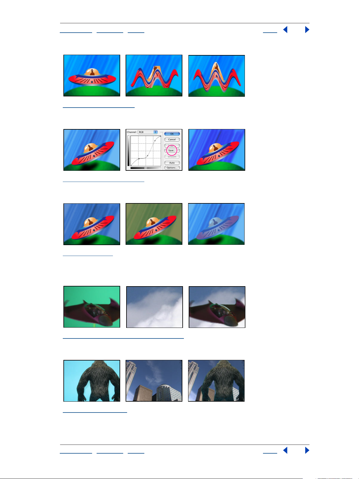
“Twirl” on page 86 Original (left) and with variations of Twirl applied (center and right)
“Warp” on page 87 Original (left) and with variations of Warp applied (center and right)
“Wave Warp” on page 87 Original (left) and with variations of Wave Warp applied (center and right)
Image Control effects
“Change Color” on page 90 Original (left) and with variations of Change Color applied (center and
right)
“Change to Color (formerly Change Color HLS)” on page 91 Original (left), with Correction Matte
(center), and with Change to Color applied (right)
Using Help | Contents | Index Back 15
Page 16
Adobe After Effects Help Gallery of effects
Using Help | Contents | Index Back 16
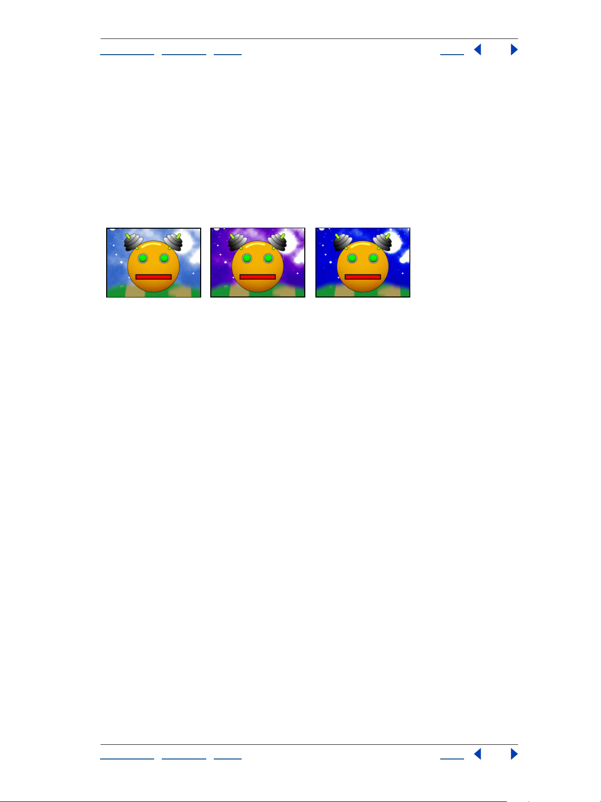
“Color Balance (HLS)” on page 92 Original (left) and with variations of Color Balance HLS applied
(center and right)
“Color Link” on page 92 Original (left) and with variations of Color Link applied (center and right)
“Colorama” on page 94 Original (left) and with variations of Colorama applied (center and right)
“Equalize” on page 98 Original (left) and with variations of Equalize applied (center and right)
“Gamma/Pedestal/Gain” on page 98 Original (left) and with variations of Gamma/Pedestal/Gain
applied (center and right)
Using Help | Contents | Index Back 16
Page 17
Adobe After Effects Help Gallery of effects
Using Help | Contents | Index Back 17
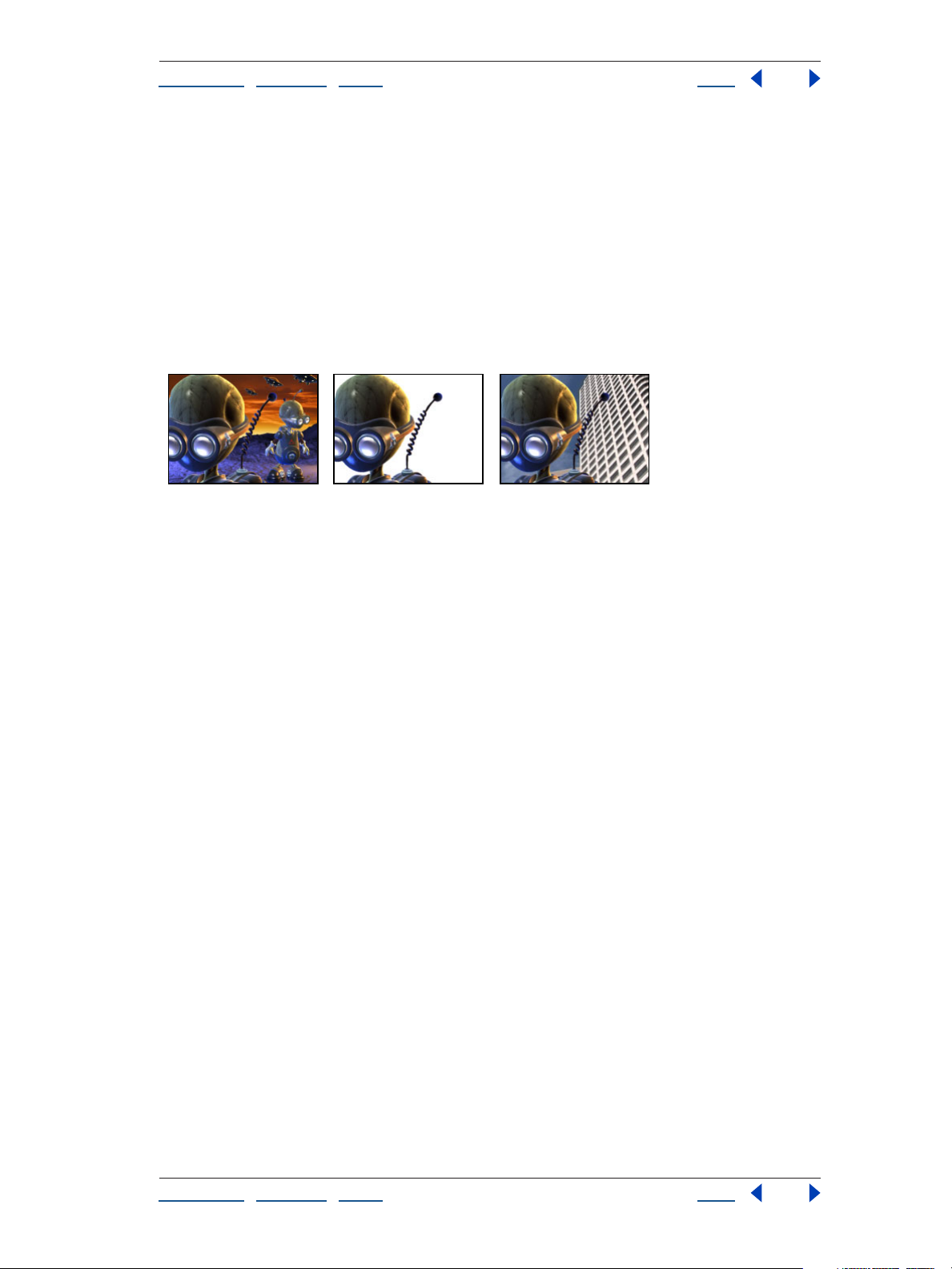
“Grow Bounds” on page 99 Original (left); the Wave Warp effect is constrained by the dimensions
of the layer (center); Grow Bounds fixes this problem (right).
“PS Arbitrary Map” on page 99 Original (left), a map created in Photoshop (center), and with PS
Arbitrary Map applied (right)
“Tint” on page 100 Original (left) and with variations of Tint applied (center and right)
Keying effects
“Color Difference Key (Pro only)” on page 101 Original (left) and background layer (center) are
combined using Color Difference Key (right).
“Color Key” on page 103 A nonstandard key color (left) and the background (center) are combined
using Color Key (right).
Using Help | Contents | Index Back 17
Page 18
Adobe After Effects Help Gallery of effects
Using Help | Contents | Index Back 18
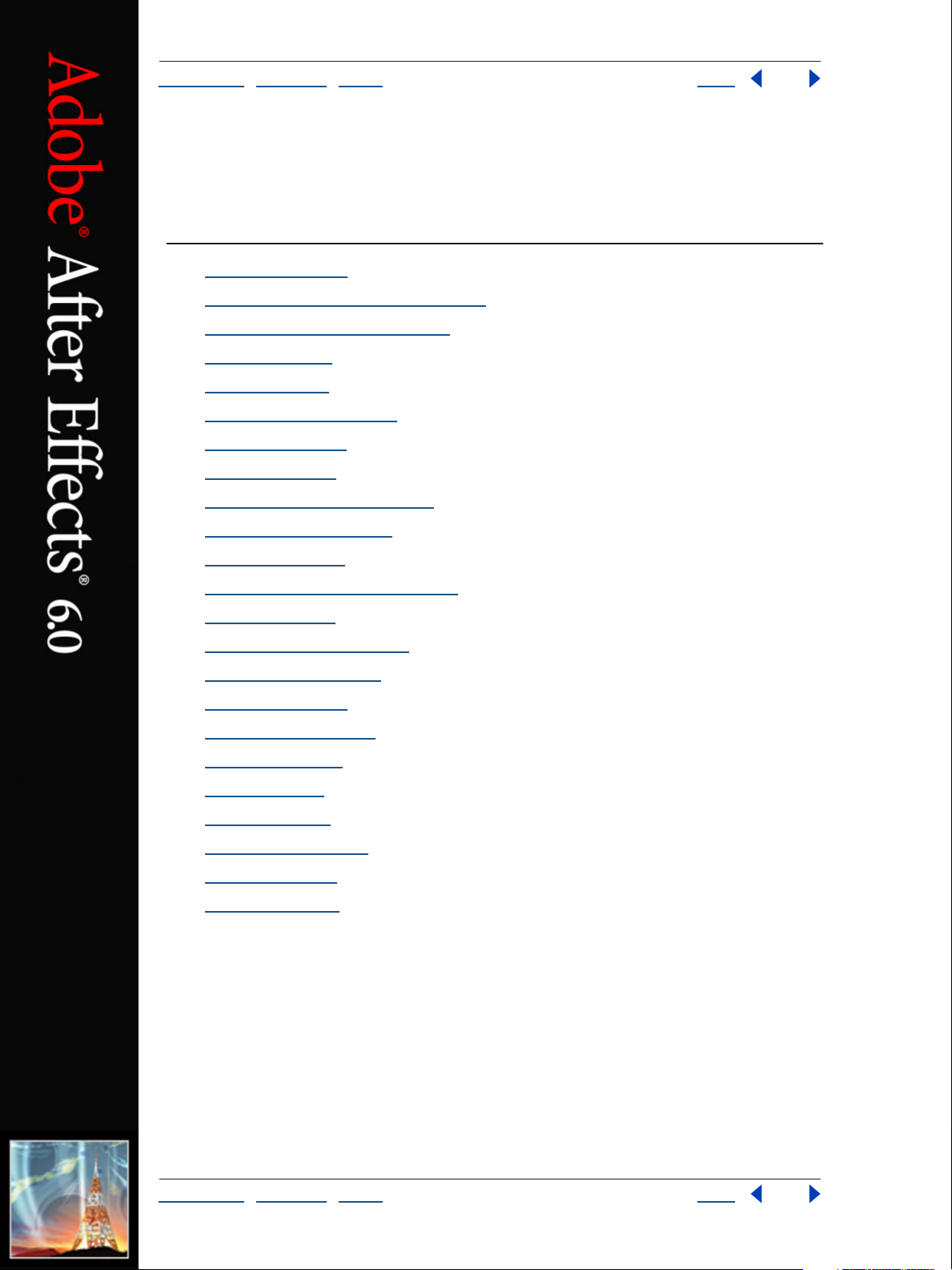
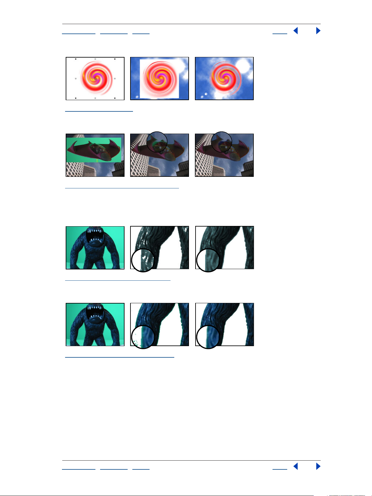
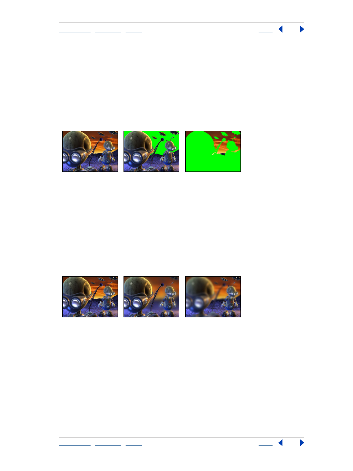
“Color Range” on page 104 A poorly lit green screen (left) and a background layer (center) are
combined using the Color Range Key (right).
“Difference Matte (Pro only)” on page 105 Original (left), Matte Only view of keyed-out subject
(center), and composite of subject with new background (right)
“Extract (Pro only)” on page 106 Original with glare (left) and background layer (center) are
combined using Extract (right).
“Inner/Outer Key (Pro only)” on page 107 The original masked layer (left) and the background
layer (center) are combined using Inner/Outer Key (right).
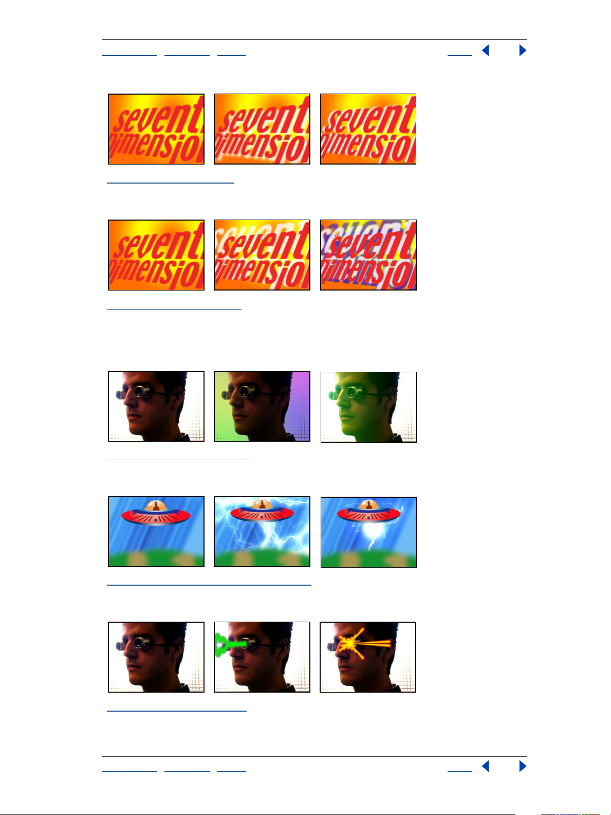
“Linear Color Key (Pro only)” on page 108 Features such as these eyes (left) that closely match the
background (center) can become transparent when using keys; Linear Color Key keeps them opaque
with the Keep This Color control (right).
Using Help | Contents | Index Back 18
Page 19
Adobe After Effects Help Gallery of effects
Using Help | Contents | Index Back 19
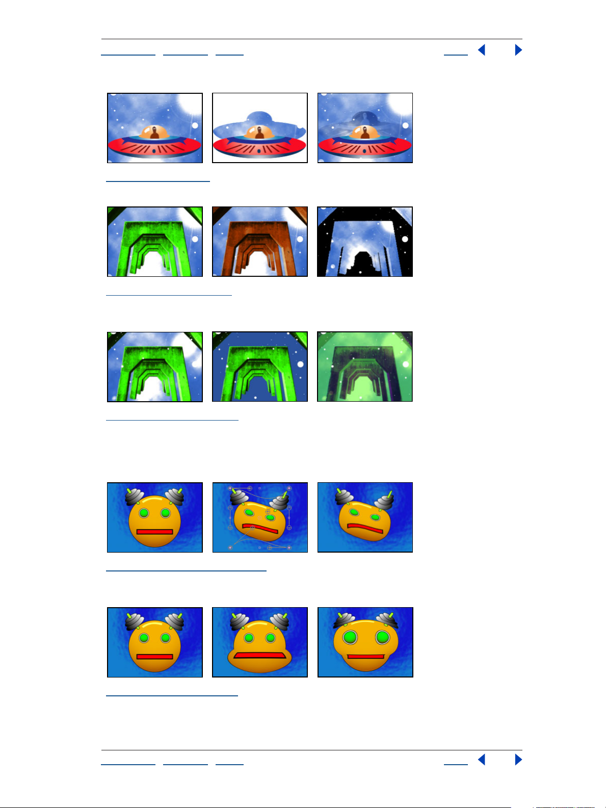
“Luma Key” on page 110 A white background of the original (left and center) is removed using
Luma Key (right).
“Spill Suppressor (Pro only)” on page 111 The original green key (left) leaves a green glow when
keyed out (center). Spill Suppressor removes the glow (right).
Matte Tools effects
“Matte Choker (Pro only)” on page 113 Original (left) shows areas of unwanted transparency after
using Color Key (center) that are removed with Matte Choker (right).
“Simple Choker (Pro only)” on page 114 The original (left) contains unwanted edges after keying
(center) that are removed with Simple Choker (right).
Using Help | Contents | Index Back 19
Page 20
Adobe After Effects Help Gallery of effects
Using Help | Contents | Index Back 20
Noise effects
“Dust & Scratches” on page 115 Scratches (left), enlarged view of scratches (center), and scratches
removed with loss of clarity (right
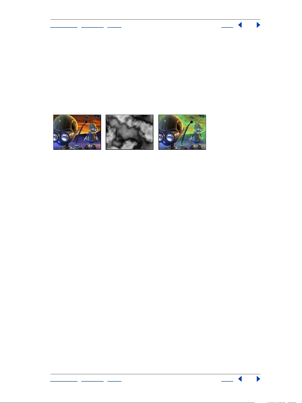
“Fractal Noise (Pro only)” on page 115 Original (left) and with variations of Fractal Noise applied
(center and right)
“Median” on page 119 Original (left) and with variations of Median applied (center and right)
“Noise” on page 120 Original (left) and with variations of Noise applied (center and right)
“Noise Alpha” on page 120 Original (left) and with variations of Noise Alpha applied (center and
right)
Using Help | Contents | Index Back 20
Page 21
Adobe After Effects Help Gallery of effects
Using Help | Contents | Index Back 21
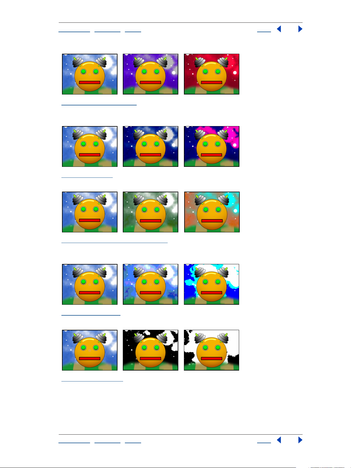
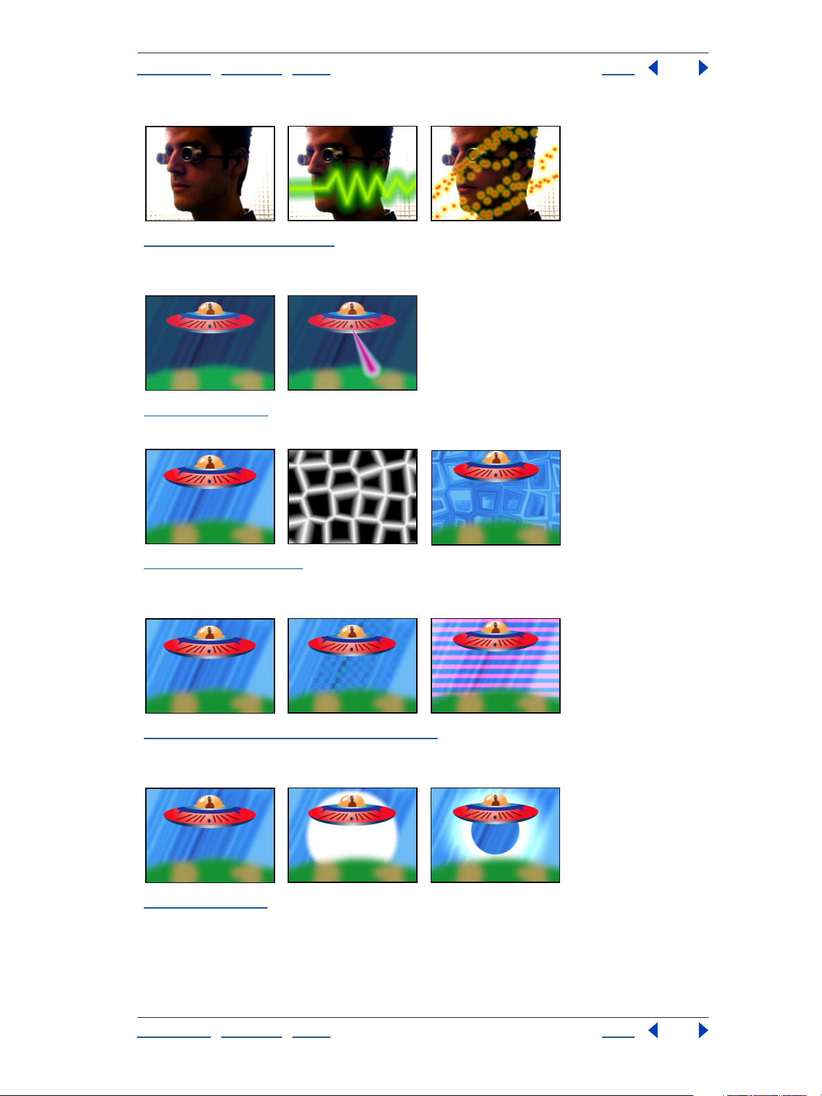
“Noise HLS, Noise HLS Auto” on page 121 Original Layer (left), Noise HLS (center), and two appli-
cations of Noise HLS with low Saturation values (right)
Paint
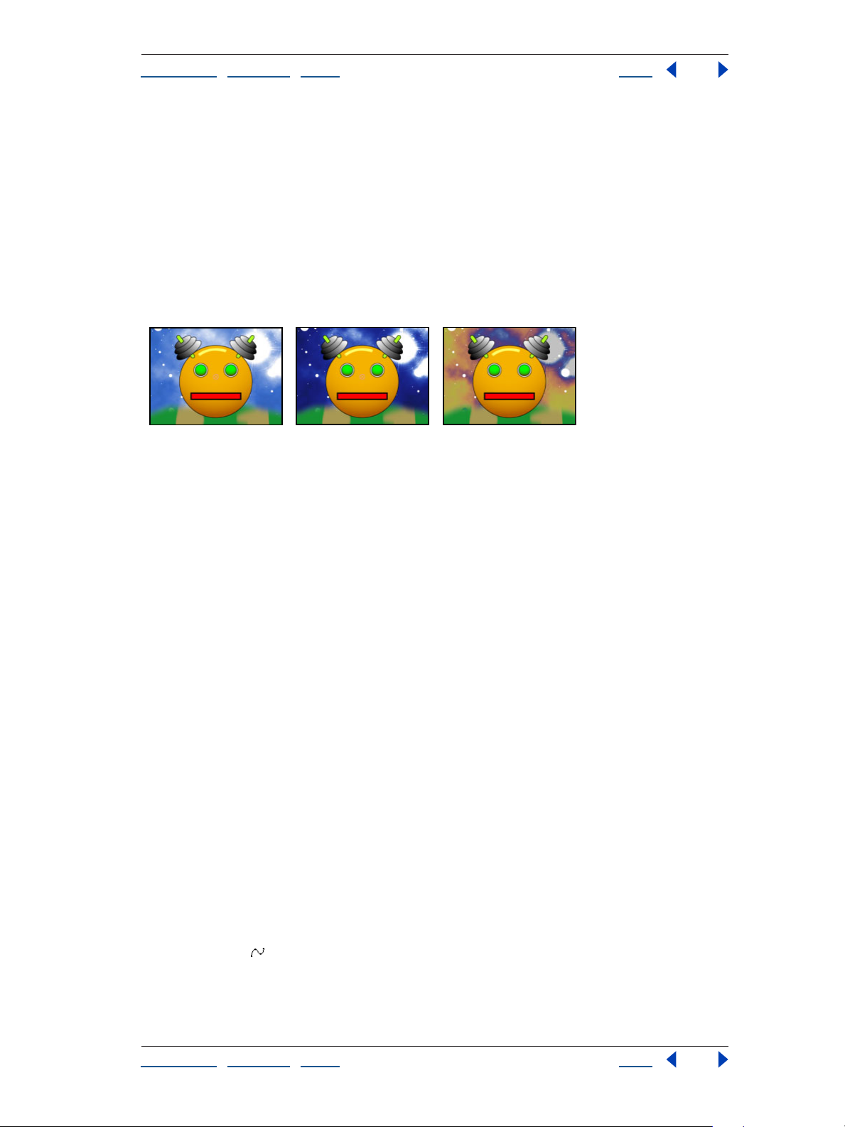
“Vector Paint (Pro only)” on page 123 Two strokes in different colors painted on the robot's
antenna, using three variations of Vector Paint
Perspective effects
“Basic 3D” on page 138 Original (left) and with variations of Basic 3D applied (center and right)
“Bevel Alpha” on page 139 Original (left) and with variations of Bevel Alpha applied (center and
right)
“Bevel Edges” on page 139 Original (left), background layer visible (center), and with the Bevel
Edges applied to the background layer (right)
Using Help | Contents | Index Back 21
Page 22
Adobe After Effects Help Gallery of effects
Using Help | Contents | Index Back 22
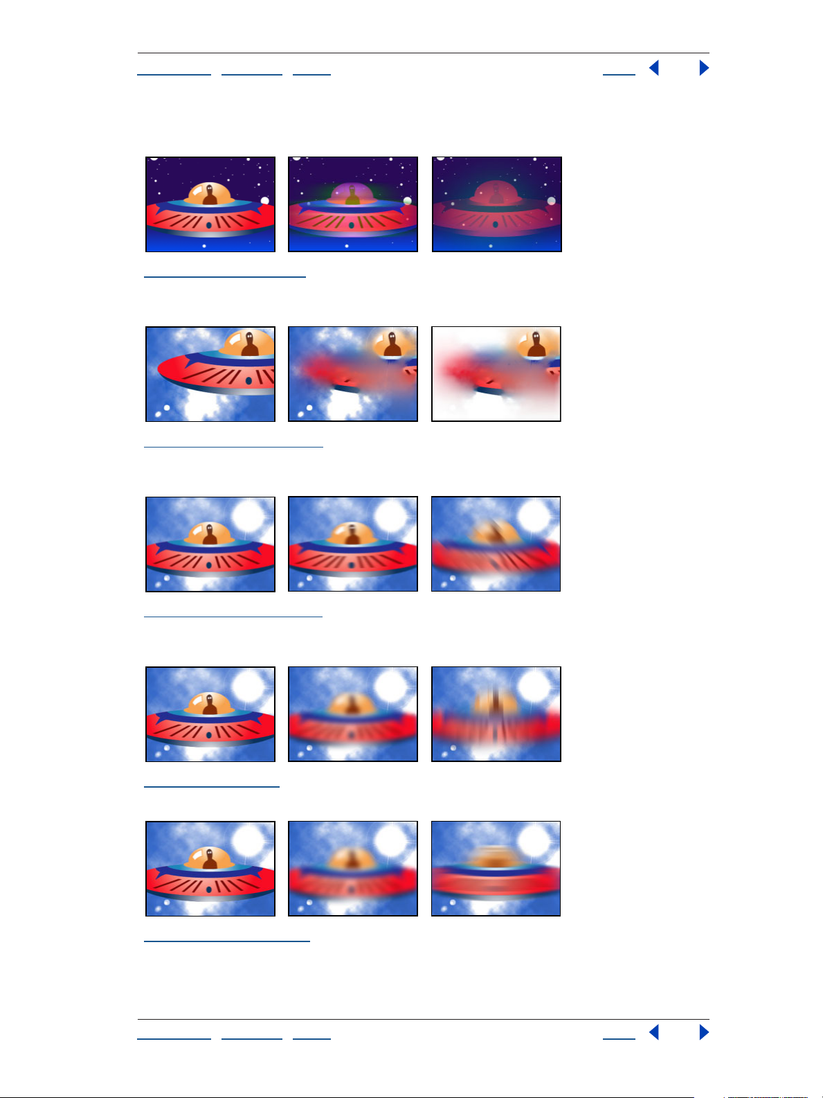
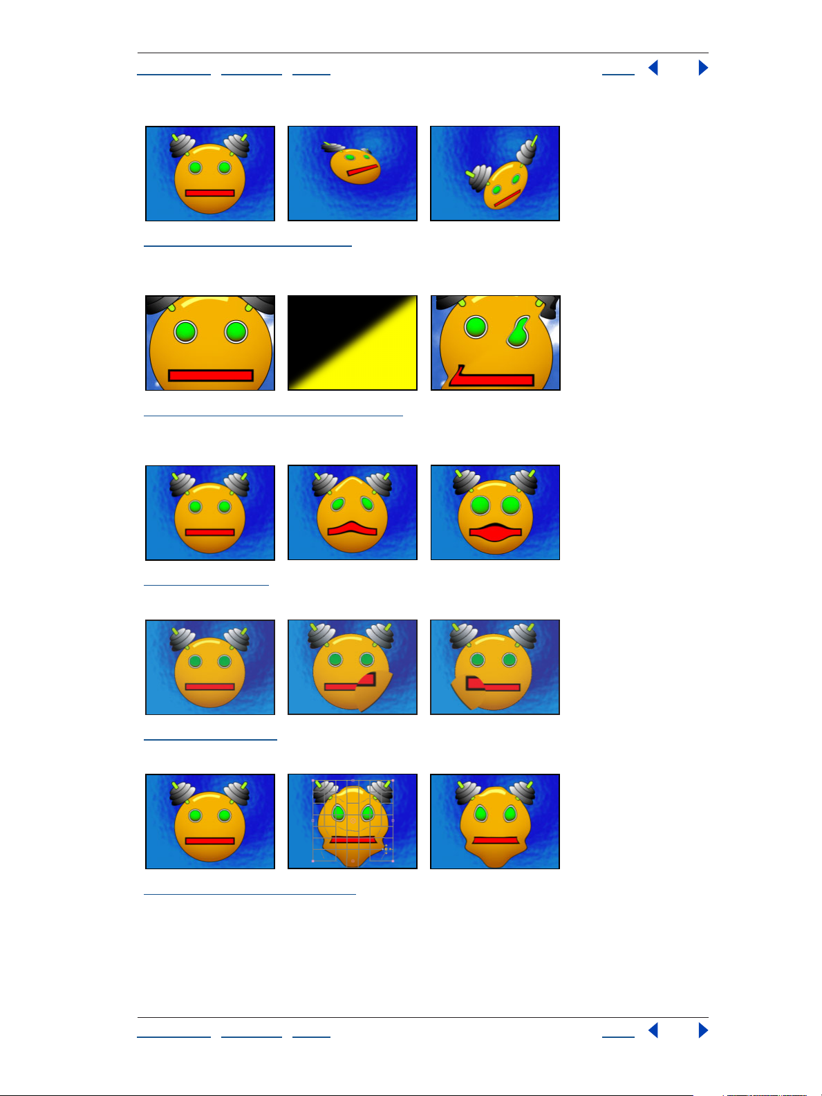
“Drop Shadow” on page 140 Original (left) and with variations of Drop Shadow applied (center and
right)
“Radial Shadow” on page 140 Original (left), with Radial Shadow applied once (center), and with
the effect applied twice (right)
Render effects
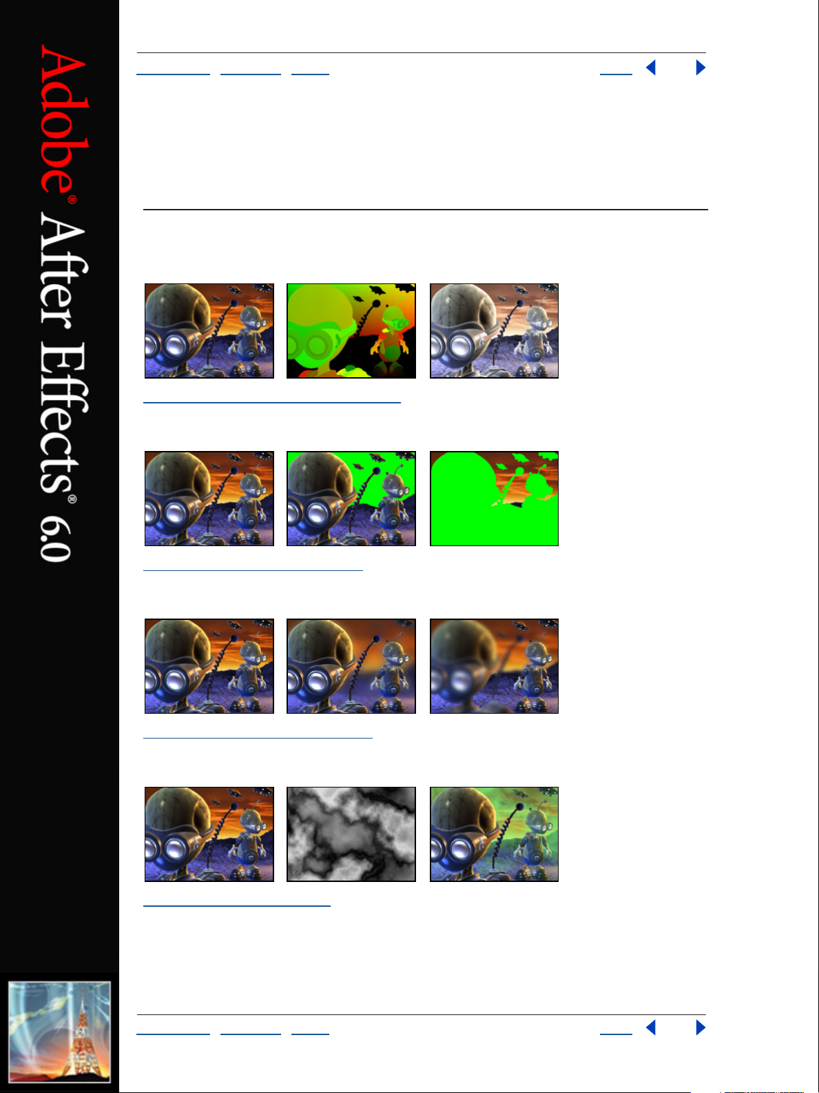
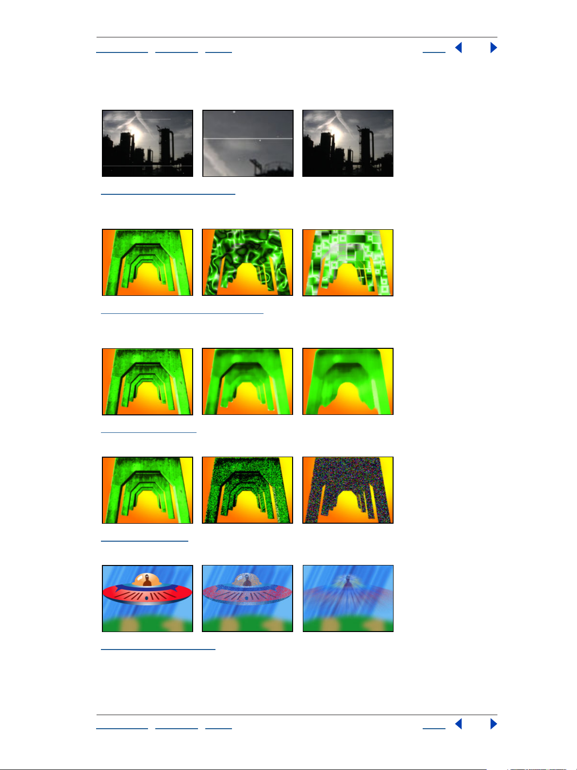
“4-Color Gradient” on page 142 Original (left) and with variations of 4-Color Gradient applied
(center and right)
“Advanced Lightning (Pro only)” on page 142 Multiple applications of the effect using the
Breaking lightning type (center) and the Bouncey lightning type (right)
“Audio Spectrum” on page 145 Original (left) and with variations of Audio Spectrum applied
(center and right)
Using Help | Contents | Index Back 22
Page 23
Adobe After Effects Help Gallery of effects
Using Help | Contents | Index Back 23
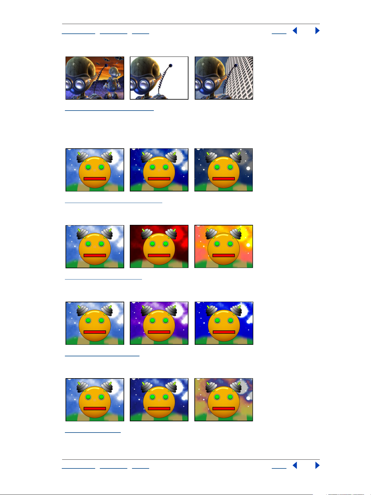
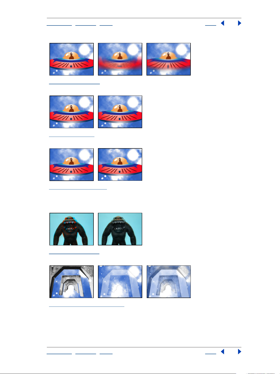
“Audio Waveform” on page 146 Original (left) and with variations of Audio Waveform applied
(center and right)
“Beam” on page 147 Original (left) and with Beam applied (right)
“Cell Pattern” on page 147 The crystal cell pattern creates a displacement map (center) that is used
with the Displacement Map effect (right).
“Checkerboard (formerly Checker)” on page 150 Original (left) and with variations of Checker-
board applied (center and right)
“Circle” on page 151 Original (left) and with variations of Circle applied (center and right)
Using Help | Contents | Index Back 23
Page 24
Adobe After Effects Help Gallery of effects
Using Help | Contents | Index Back 24
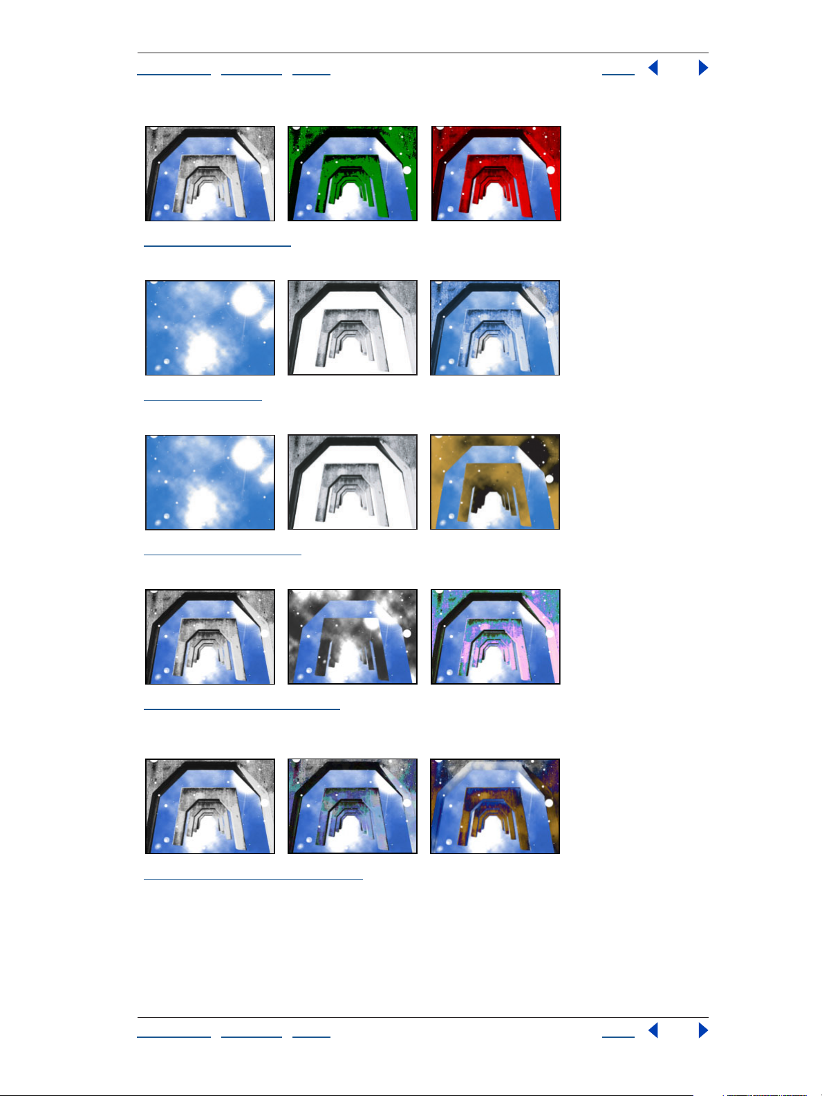
“Ellipse” on page 152 Original (left), with Ellipse applied once (center), and with Ellipse applied
multiple times (right)
“Eyedropper Fill (formerly Color Picker)” on page 152 Original (left) and with variations of
Eyedropper Fill applied (center and right)
“Fill” on page 153 A mask (left) is used with the Fill effect (center); a different mask is used (right).
“Fractal” on page 153 Original (left) and with variations of Fractal applied (center and right)
“Grid” on page 155 Original (left) and with variations of Grid applied (center and right)
Using Help | Contents | Index Back 24
Page 25
Adobe After Effects Help Gallery of effects
Using Help | Contents | Index Back 25
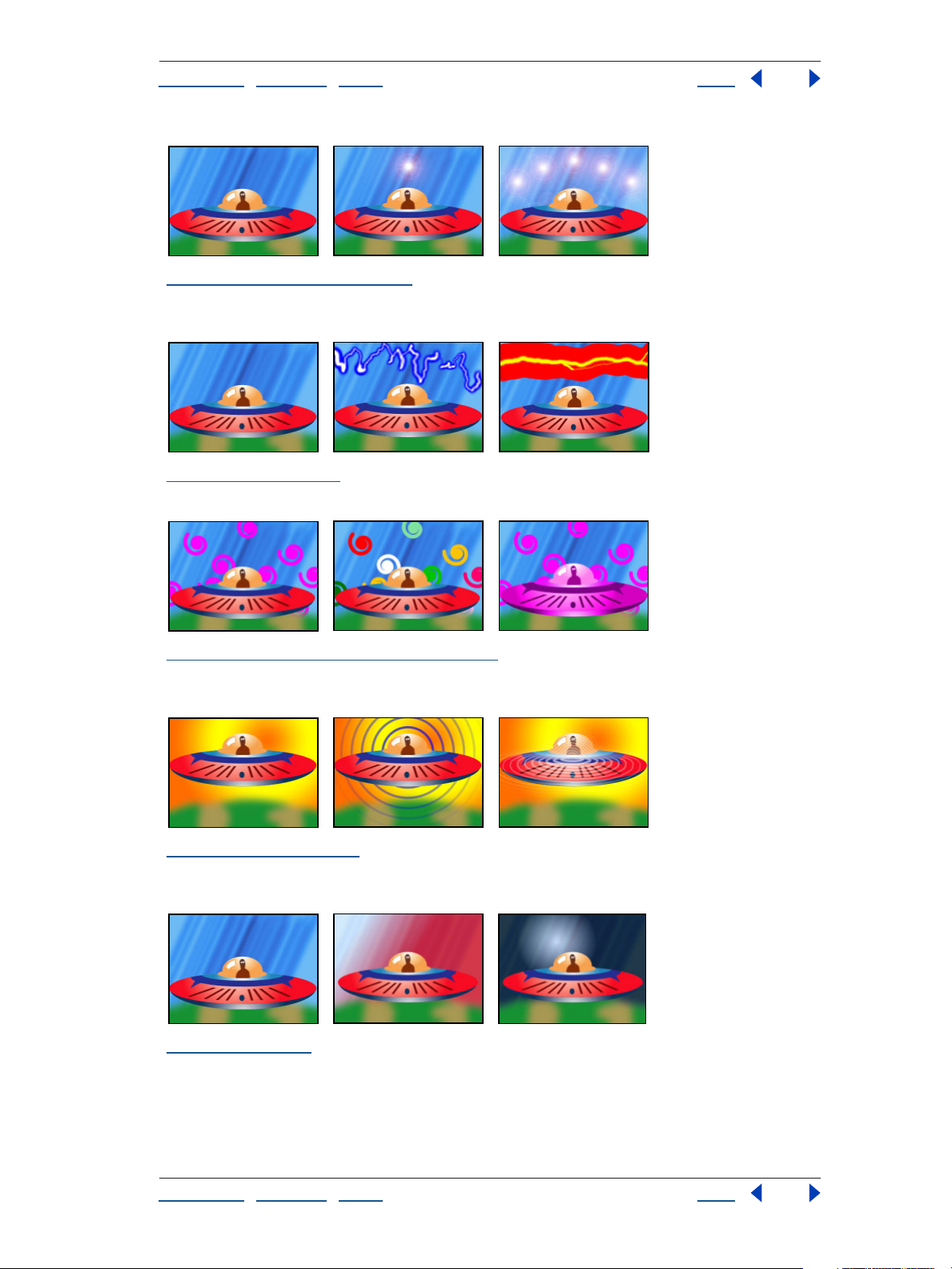
“Lens Flare (Pro only)” on page 156 Original (left) and with variations of Lens Flare applied (center
and right)
“Lightning” on page 156 Original (left) and with variations of Lightning applied (center and right)
“Paint Bucket (formerly Basic Fill)” on page 158 Original (left) and with variations of Paint Bucket
applied (center and right)
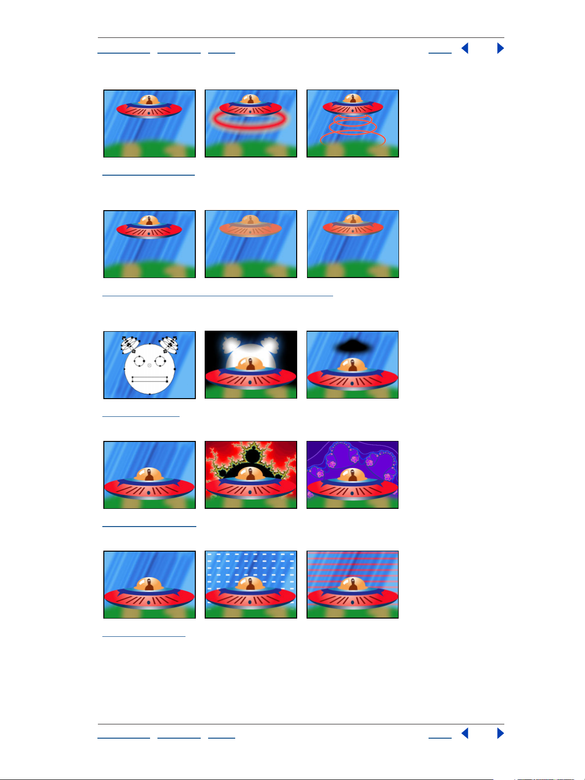
“Radio Waves” on page 160 Original (left) and with variations of Radio Waves applied (center and
right)
“Ramp” on page 163 Original (left) and with variations of Ramp applied (center and right)
Using Help | Contents | Index Back 25
Page 26
Adobe After Effects Help Gallery of effects
Using Help | Contents | Index Back 26
“Scribble” on page 163 Original with masks (left) and with variations of Scribble applied (center
and right)
“Stroke” on page 165 Original (left), with mask (center), and with Stroke applied (right)
“Vegas” on page 165 Original (left) and with variations of Vegas applied (center and right)
Simulation effects
“Card Dance” on page 168 Top: Original (left) and with Card Dance applied using different rotations
(center and right) Bottom: Original (left), gradient layer (center), and with Card Dance applied using
the gradient layer (right)
Using Help | Contents | Index Back 26
Page 27
Adobe After Effects Help Gallery of effects
Using Help | Contents | Index Back 27
“Caustics” on page 172 Bottom layer (left), water layer (center), and with Caustic applied (right)
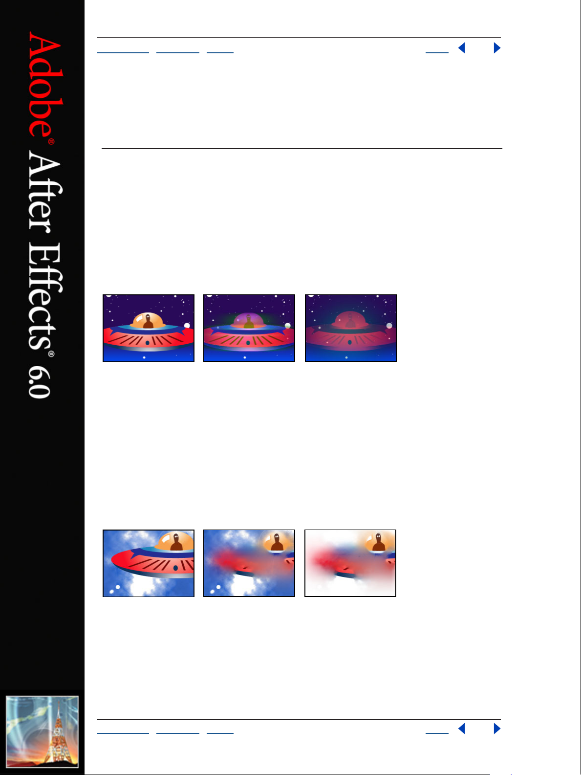
“Foam” on page 175 Original (left), with Foam applied (center), and with a robot layer used as the
Bubble Texture Layer (right)
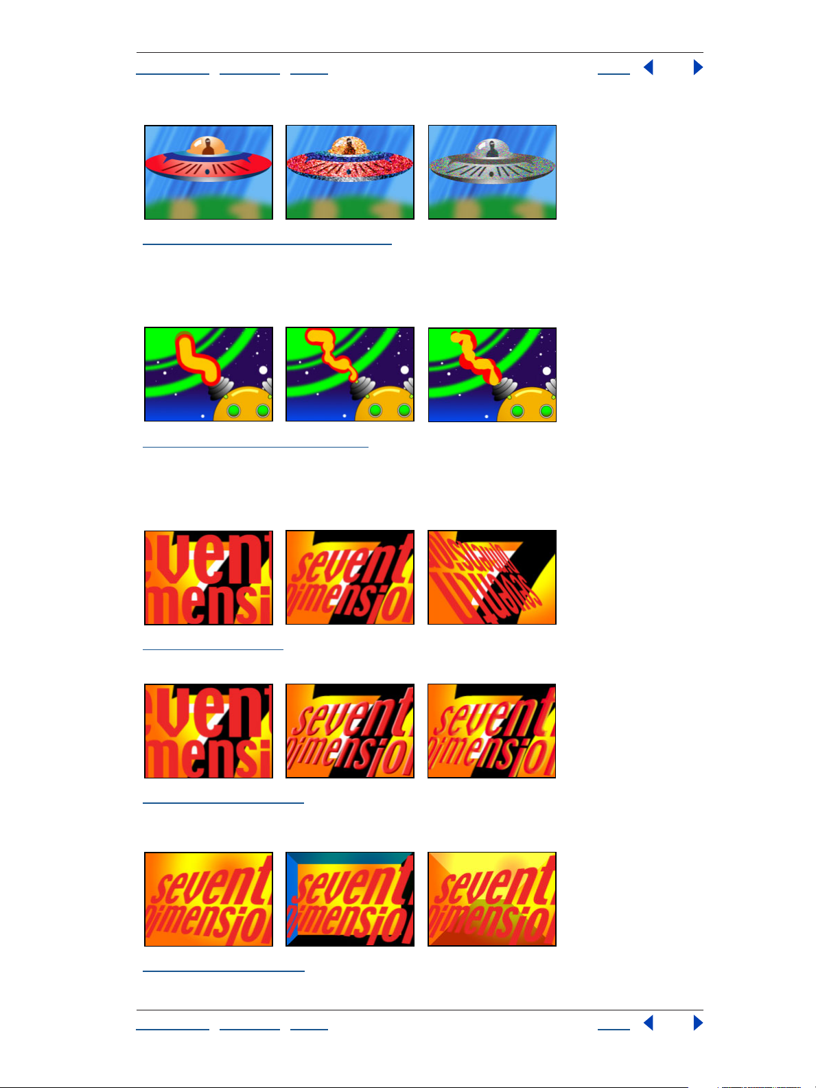
“Particle Playground (Pro only)” on page 180 Effect with variations of Canon (left), Particle
Exploder (center), and Layer Exploder (right)
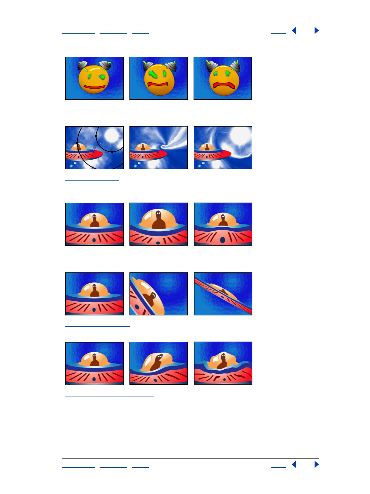
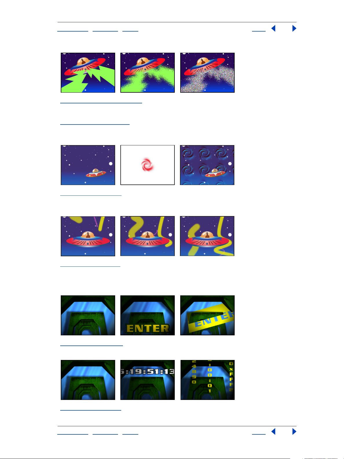
“Shatter” on page 197 Original (left) and with Shatter applied over time to reveal another layer
(center and right)
Using Help | Contents | Index Back 27
Page 28
Adobe After Effects Help Gallery of effects
Using Help | Contents | Index Back 28
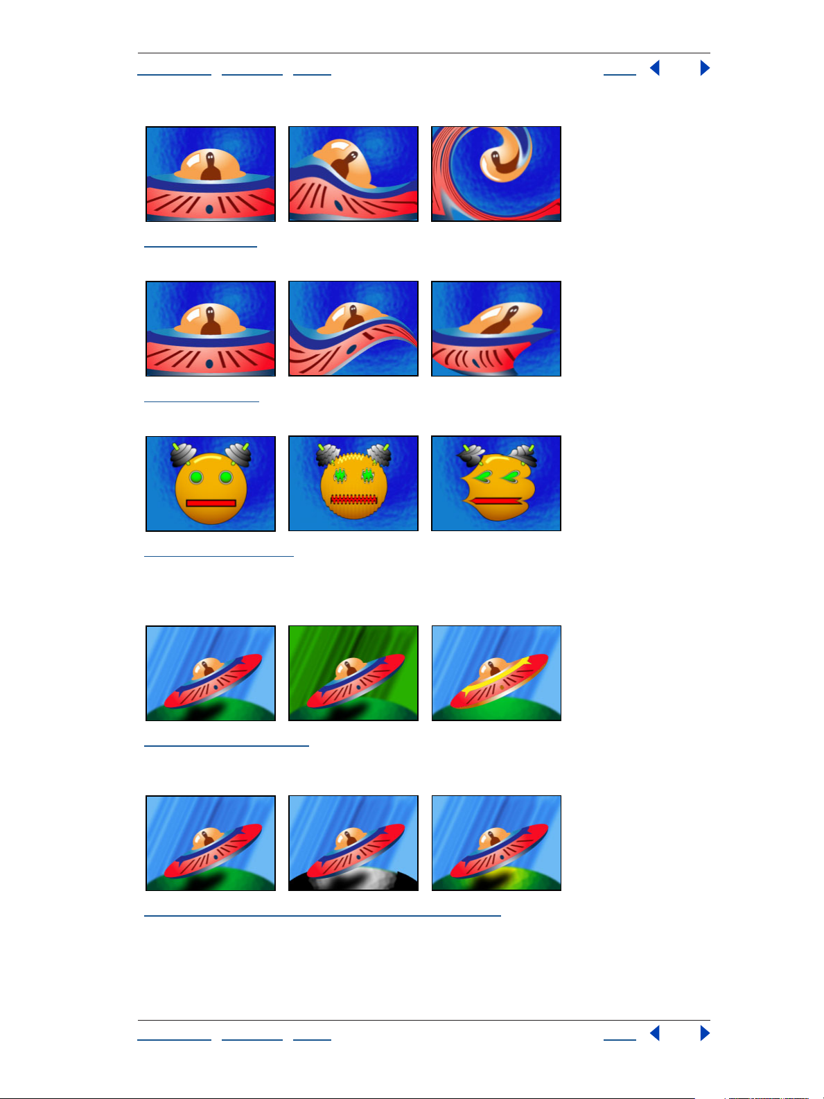
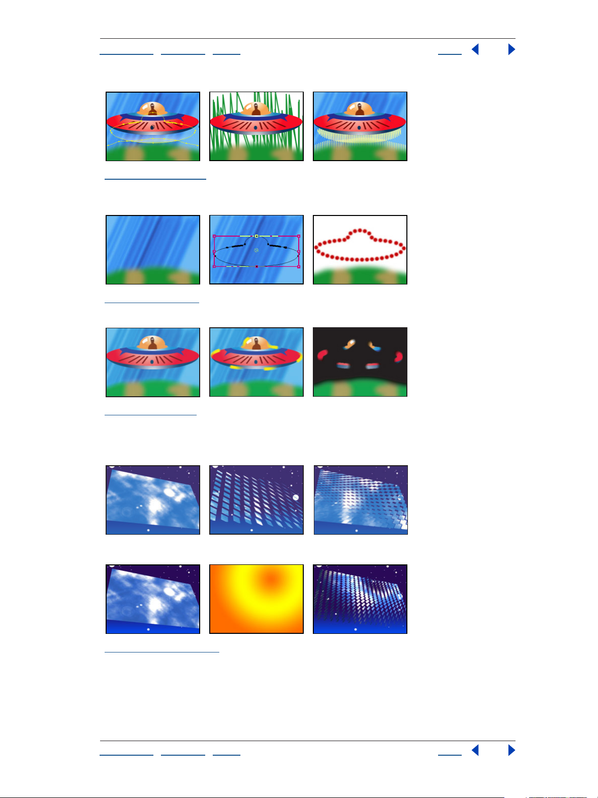
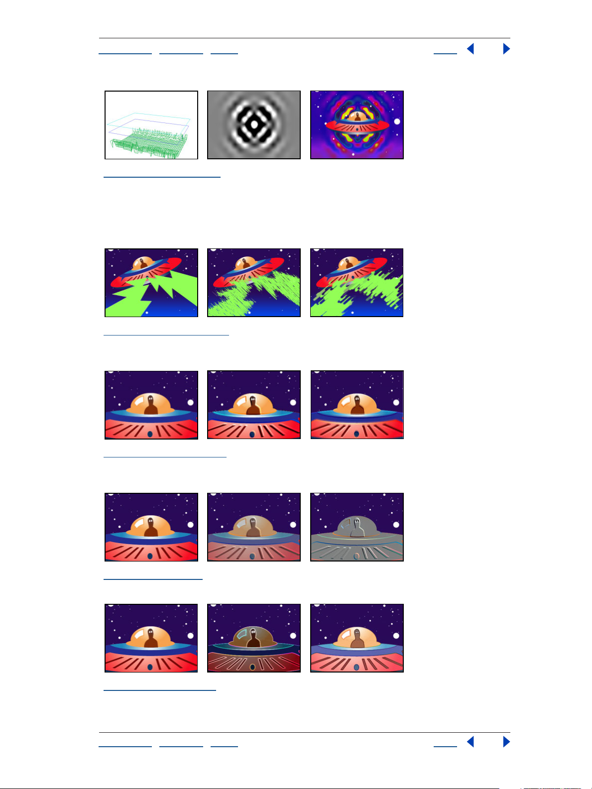
“Wave World” on page 204 Top: Wireframe view (left), Height Map view (center), and the resulting
image used as the water surface of the Caustics effect (right) Bottom: Wireframe view (left), Height
Map view (center), and the resulting image used with the Colorama effect (right)
Stylize effects
“Brush Strokes” on page 208 Original (left) and with variations of Brush Strokes applied (center
and right)
“Color Emboss” on page 209 Original (left) and with variations of Color Emboss applied (center and
right)
“Emboss” on page 209 Original (left) and with variations of Emboss applied (center and right)
“Find Edges” on page 209 Original (left) and with variations of Find Edges applied (center and
right)
Using Help | Contents | Index Back 28
Page 29
Adobe After Effects Help Gallery of effects
Using Help | Contents | Index Back 29
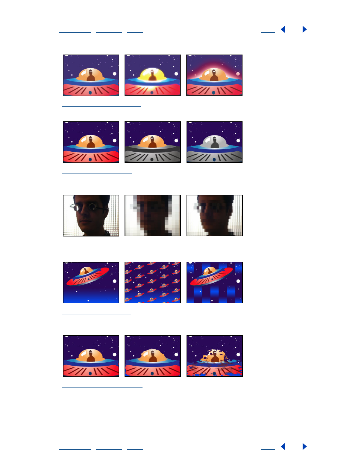
“Glow (Pro only)” on page 210 Original (left) and with variations of Glow applied (center and right)
“Leave Color” on page 212 Original (left) and with variations of Leave Color applied (center and
right)
“Mosaic” on page 212 Original (left) and with variations of Mosaic applied (center and right)
“Motion Tile” on page 213 Original (left) and with variations of Motion Tile applied (center and
right)
“Roughen Edges” on page 214 Original (left) and Edge Type set to Roughen (center) and Rusty
Color (right) with all controls set to maximum values
Using Help | Contents | Index Back 29
Page 30
Adobe After Effects Help Gallery of effects
Using Help | Contents | Index Back 30
“Scatter (Pro only)” on page 216 Original (left), after applying Scatter (center), and then applying
the Noise effect (right)
“Strobe Light” on page 216 This effect is difficult to illustrate. See the online Effects Help for infor-
mation on using this effect.
“Texturize” on page 217 Original (left), a layer used to create texture (center), and the texture
applied to background layer (right)
“Write-on” on page 217 Three strokes are animated through time (left, center, and right).
Text effects
“Basic Text” on page 219 Original (left) and with variations of Basic Text applied (center and right)
“Numbers” on page 220 Original (left) and with variations of Numbers applied (center and right)
Using Help | Contents | Index Back 30
Page 31

Adobe After Effects Help Gallery of effects
Using Help | Contents | Index Back 31
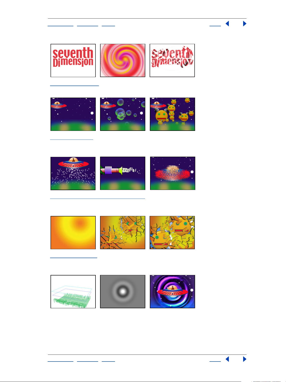
“Path Text” on page 222 Original (left) and with variations of Path Text applied (center and right)
Time effects
“Echo” on page 228 Three subsequent frames showing echo effect
“Posterize Time” on page 229 This effect is difficult to illustrate. See the online Effects Help for
information on using this effect.
“Time Difference” on page 230 This effect is difficult to illustrate. See the online Effects Help for
information on using this effect.
“Time Displacement (Pro only)” on page 231 Original (left), a layer used to displace the image as
time progresses (center), and the result (right)
Transition effects
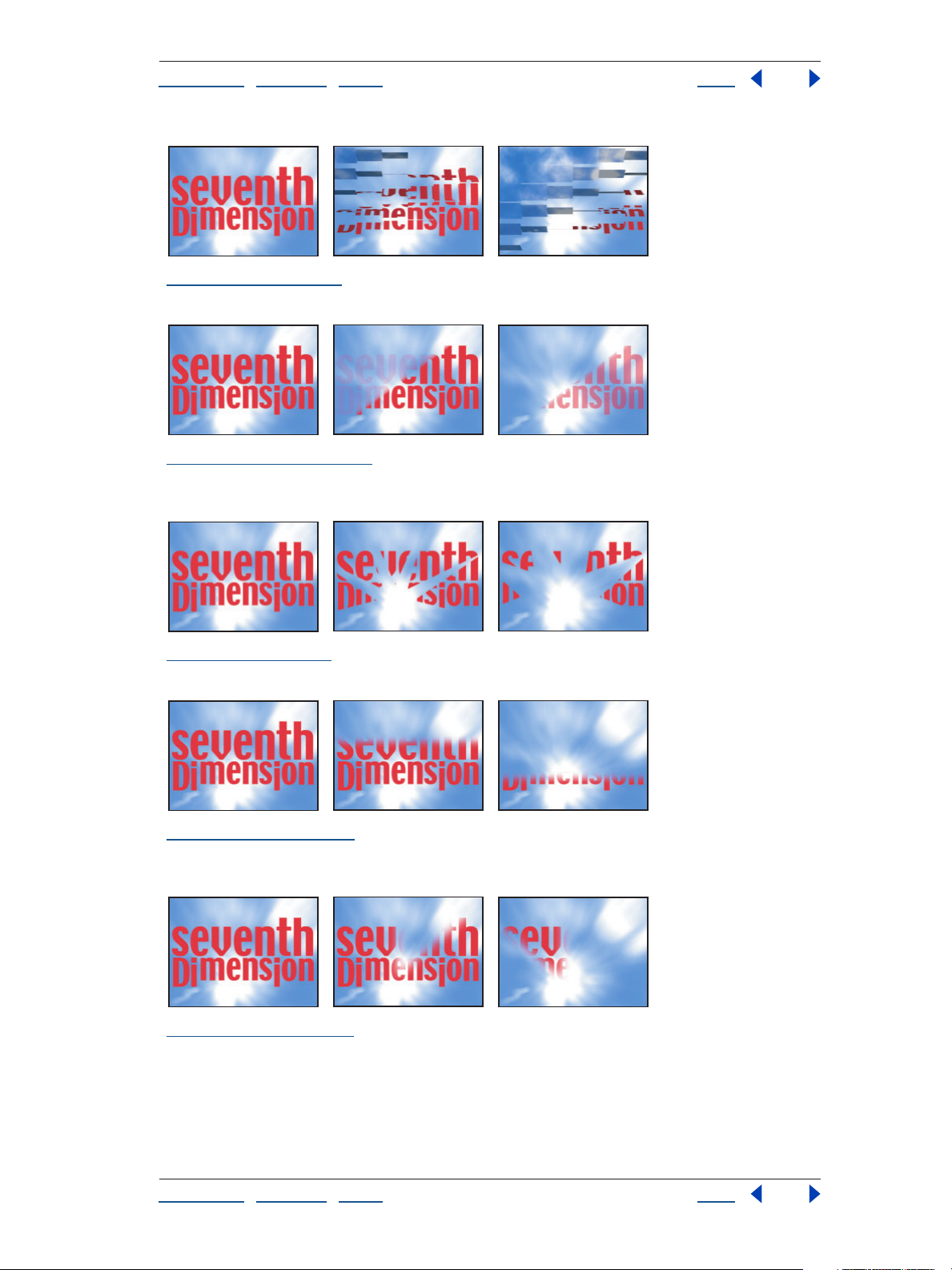
“Block Dissolve” on page 234 Original (left) and with variations of Block Dissolve applied (center
and right)
Using Help | Contents | Index Back 31
Page 32
Adobe After Effects Help Gallery of effects
Using Help | Contents | Index Back 32
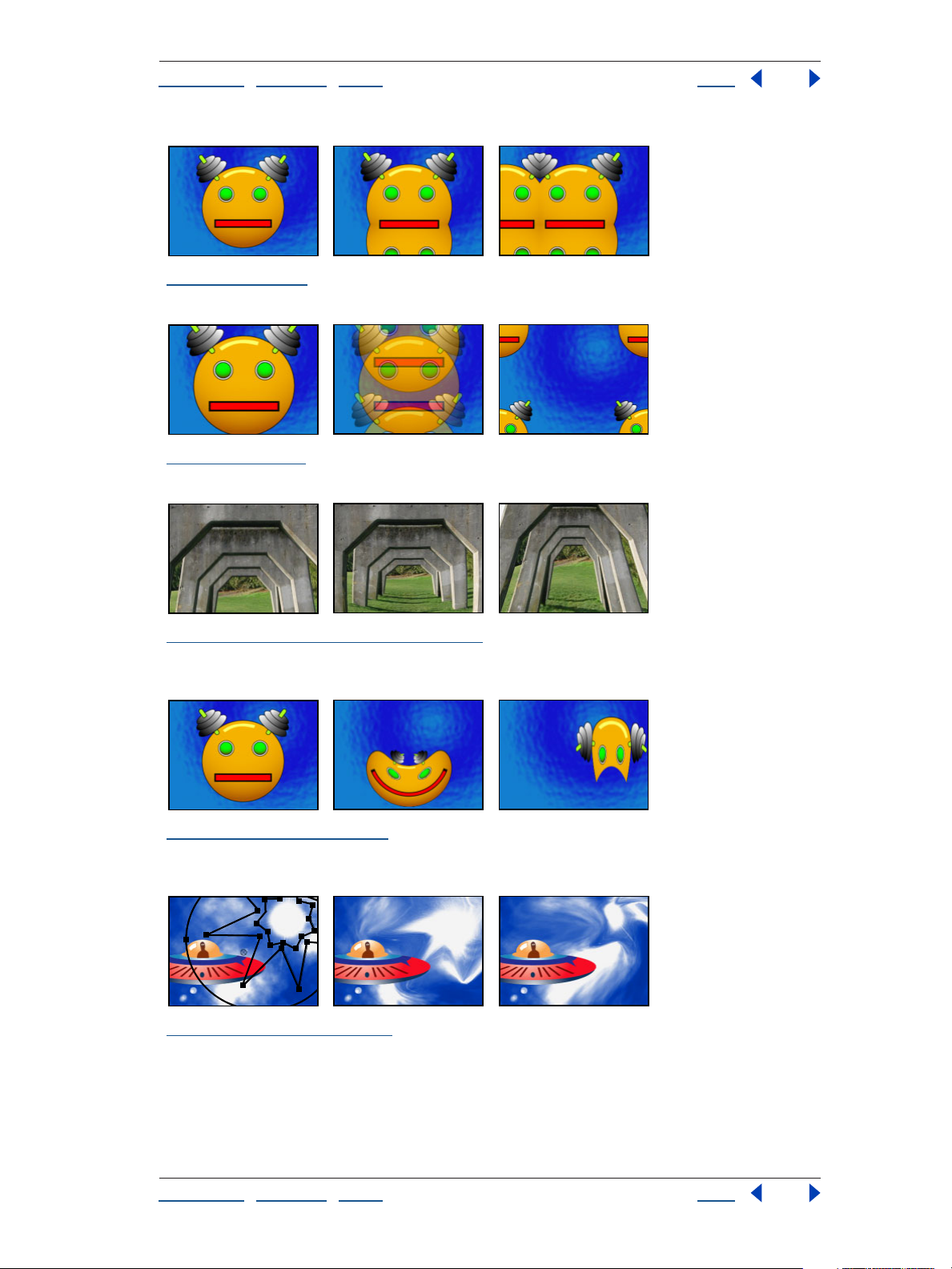
“Card Wipe” on page 234 Original (left) and with variations of Card Wipe applied (center and right)
“Gradient Wipe” on page 238 Original (left) and with variations of Gradient Wipe applied (center
and right)
“Iris Wipe” on page 239 Original (left) and with variations of Iris Wipe applied (center and right)
“Linear Wipe” on page 239 Original (left) and with variations of Linear Wipe applied (center and
right)
“Radial Wipe” on page 239 Original (left) and with variations of Radial Wipe applied (center and
right)
Using Help | Contents | Index Back 32
Page 33
Adobe After Effects Help Gallery of effects
Using Help | Contents | Index Back 33
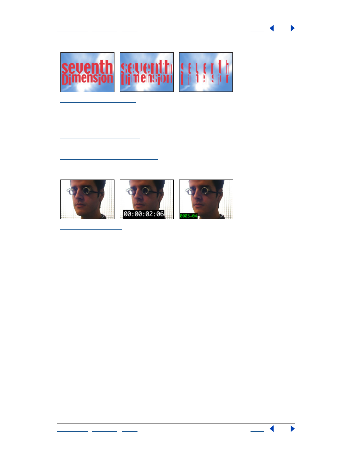
“Venetian Blinds” on page 240 Original (left) and with variations of Venetian Blinds applied (center
and right)
Video effects
“Broadcast Colors” on page 241 This effect is difficult to illustrate. See the online Effects Help for
information on using this effect.
“Reduce Interlace Flicker” on page 242 This effect is difficult to illustrate. See the online Effects
Help for information on using this effect.
“Timecode” on page 242 Original (left) and with variations of Timecode applied (center and right)
Using Help | Contents | Index Back 33
Page 34

Adobe After Effects Help Effects included with After Effects
Using Help | Contents | Index Back 34
Effects included with After Effects
Standard effects
Adobe® After Effects includes an array of visual and audio effects. And, because of the
After Effects plug-in technology, you can use additional effects from other Adobe plug-in–
compatible applications, such as Adobe Photoshop. When you register your copy of After
Effects, you can download the following effects from the After Effects product section on
Adobe’s Web site: Card Dance, Card Wipe, Caustics, Foam, and Wave World.
To see which effects are included within each effect category, see the table of contents in
the online Effects Help.
Note: If an effect is 16 bit, its icon in the Effects palette is denoted with a “16” . All other
effects are denoted with the standard effects icon .
What you get with the Professional edition
The Professional Edition of After Effects includes all of the effects available in the Standard
Edition, as well as the following effects:
Adjust Color Stabilizer
3D Channel 3D Channel Extract, Depth Matte, Depth of Field, Fog 3D, and ID Matte
Audio Flange & Chorus, High-Low Pass, Modulator, Parametric EQ, Reverb, and Tone
Channel Alpha Levels
Distort Bezier Warp, Bulge, Corner Pin, Displacement Map, Mesh Warp, Optics Compen-
sation, and Reshape
Keying Color Difference Key, Difference Matte, Extract, Inner/Outer Key, Linear Color Key,
and Spill Suppressor
Matte To ols Matte Choker and Simple Choker
Noise Fractal Noise
Paint Vector Paint
Render Advanced Lightning
Simulation Particle Playground
Stylize Glow and Scatter
Time Time Displacement
Using Help | Contents | Index Back 34
Page 35
Adobe After Effects Help 3D Channel effects (Pro only)
Using Help | Contents | Index Back 35
3D Channel effects (Pro only)
Overview
The After Effects Professional Edition provides tools to integrate 3D scenes into 2D
composites, and to make changes to those 3D scenes. You can import 3D channel image
files saved in RLA, RPF, Softimage PIC/ZPIC, and Electric Image EI/EIZ formats. For PIC and
EI files, the 3D channel information is in the ZPIC or EIZ files, respectively. You don’t
actually import ZPIC and EIZ files, but as long as they’re stored in the same folder with the
PIC and EI files, you have access to their 3D channels using the 3D Channel effects. The 3D
Channel effects don’t affect other types of files.
3D Channel effects read and manipulate the additional channels of information, including
z-depth, surface normals, object ID, texture coordinates, background color, unclamped
RGB, and material ID. You can layer 3D elements along a
3D scene, blur areas in a 3D scene, isolate 3D elements, apply a foggy effect with depth,
and extract 3D channel information for use as parameters in other effects.
z axis, insert other elements in a
Note: Apply 3D Channel effects to 2D layers that have the auxiliary information. If you
convert a layer to 3D and view it from anywhere else but the front and center, it doesn’t
appear as expected.
3D Channel Extract (Pro only)
The 3D Channel Extract effect makes auxiliary channels visible as either grayscale or multichannel color images. You can then use the resulting layer as parameters for other effects.
For example, extract the
an influence map in the Particle Playground effect, or extract values from the Unclamped
RGB channel to produce a matte that generates glowing highlights.
Original (left), duplicate of original with 3D Channel Extract applied using Texture UV (center), and
original combined with duplicate using the Luminosity blending mode (right)
Adjust the following controls for the 3D Channel Extract effect:
3D Channel Specifies the channel that you want to extract from the 3D channel image
file.
z-depth information in a 3D channel image file and then use it as
White Point, Black Point Specify the value that is mapped to white or black.
Using Help | Contents | Index Back 35
Page 36
Adobe After Effects Help 3D Channel effects (Pro only)
Using Help | Contents | Index Back 36
Depth Matte (Pro only)
The Depth Matte effect reads the z-depth information in a 3D channel image file and can
slice the image anywhere along that
in front of or behind the value you specify. For example, remove a background in a 3D
scene, or insert objects into a 3D scene. Simply create two layers with the 3D channel
image file; then, in one layer, position everything behind a certain point. In the other layer,
position everything in front of that same point, so that the two layers together make up
the original image; then insert a layer between them with the object that you want to
composite into the scene.
Original (left), with Depth Matte applied to two different depth specifications (center and right)
z axis. Use this effect to create a matte for everything
Adjust the following controls for the Depth Matte effect:
Depth Specifies the depth of the z axis where you want to slice the image.
Feather Specifies the amount of feather along the slice.
Invert Inverts the feather.
Depth of Field (Pro only)
The Depth of Field effect simulates a camera that’s focusing in on one area in a 3D scene
(along the
Original (left), and with Depth of Field applied using different Focal Plane settings (center and right)
Adjust the following controls for the Depth of Field effect:
Focal Plane Specifies the specific distance, or plane, along the z axis that you want to
focus on in the 3D scene. Identify this distance by clicking different parts of the 3D scene
in the Composition window, while keeping an eye on the
Info palette. Note that you must select the effect in the Effect Controls window before you
click.
z axis) while allowing other areas to blur.
z-axis values that appear in the
Maximum Radius Describes how much blur is applied to objects outside this plane.
Focal Plane Thickness Determines the depth of the region that’s in focus.
Using Help | Contents | Index Back 36
Page 37
Adobe After Effects Help 3D Channel effects (Pro only)
Using Help | Contents | Index Back 37
Focal Bias Sets the speed with which the out-of-focus elements lose focus. This value
works like a gamma correction: the higher the value, the more quickly elements drop out
of focus.
Fog 3D (Pro only)
The Fog 3D effect applies fog along the z axis, so the distant parts of a 3D scene look hazier
or disappear behind the fog. Fog 3D simulates fog by behaving as though there is a
scattering medium in the air that makes objects look more and more diffuse as they get
more distant along the
Original (left), Gradient Layer (center), and with Fog 3D applied (right)
z axis.
Adjust the following controls for the Fog 3D effect:
Fog Color Specifies the color of the fog.
Fog Start Depth Determines where along the z axis the diffuse scattering begins. To
specify this point, first select different elements in the 3D scene, and note their
the Info palette.
Fog End Depth Determines where the most diffuse area appears along the z axis.
Fog Opacity Determines the opacity of the fog.
Scattering Density Determines how quickly the scattering occurs. This value works like a
gamma correction: the higher the value, the more dense the fog appears from its starting
point.
Foggy Background Creates a foggy background and is selected by default. Deselect this
control to create transparency at the back of the 3D scene for compositing on top of
another image or scene.
Gradient Layer Specifies a grayscale layer to use as medium for increasing or decreasing
the fog density. After Effects reads the luminance value in the grayscale image and applies
it as the scattering medium. You could, for example, create a gradient layer from a swirling,
drifting texture to create a more atmospheric fog effect. For best results, make sure that
the dimensions of the gradient layer are the same as the footage, not the composition.
Layer Contribution Specifies how much the gradient layer affects the resulting fog.
z depth in
Using Help | Contents | Index Back 37
Page 38
Adobe After Effects Help 3D Channel effects (Pro only)
Using Help | Contents | Index Back 38
ID Matte (Pro only)
The ID Matte effect isolates elements in a 3D channel image file. Many 3D programs tag
each element in a scene with a unique Object ID. After Effects uses this information to
create a matte that excludes everything in the scene except the element you want.
Identify each object’s Object ID by applying the ID Matte effect and then clicking different
parts of the image in the Composition window as you watch the Info palette. (You can also
identify Object IDs in the Layer window if you select the effect from the Layer window
menu first.) If you select Object ID for the Auxiliary Channel parameter in the Effect
Controls window, the slider automatically reflects the Object ID for each object you select.
In addition, you can isolate objects based on their Material ID as well.
Original (left), with ID Matte applied using the near alien as the ID Selection (center), and composited
over a new background (right)
Adjust the following controls for the ID Matte effect:
Aux. Channel Specifies whether you’re isolating elements based on their Object IDs or
their Material IDs.
ID Selection Identifies the unique ID value assigned to each element in a 3D scene.
Feather Specifies the amount of feather along the matte’s edges.
Invert Inverts the feather.
Use Coverage Creates a cleaner matte by decontaminating the pixels along the edge of
the matte. It removes the colors stored behind the object from these pixels. This is appli
cable only if your 3D channel image file contains a coverage channel that stores information about the colors behind objects.
-
Using Help | Contents | Index Back 38
Page 39

Adobe After Effects Help Adjust effects
Using Help | Contents | Index Back 39
Adjust effects
Brightness & Contrast
The Brightness & Contrast effect adjusts the brightness and contrast of the entire layer
(not individual channels). The center point of each slider is neutral and indicates no effect.
The layer’s quality setting does not affect Brightness & Contrast. Using the Brightness &
Contrast effect is the easiest way to make simple adjustments to the tonal range of the
image. It adjusts all pixel values in the image at once—highlights, shadows, and midtones.
Original (left), with background layer’s Brightness decreased and Contrast increased (center), and
with background layer’s Brightness & Contrast decreased (right)
Channel Mixer
The Channel Mixer effect modifies a color channel using a mix of the current color
channels. Use it to make creative color adjustments not easily done with the other color
adjustment tools: Create high-quality grayscale images by choosing the percentage
contribution from each color channel, create high-quality sepia-tone or other tinted
images, and swap or duplicate channels. The Constant (-Const) controls specify the base
amount of the input channel to be added to the output channel. Monochrome applies the
same settings to all the output channels, creating a color image that contains only gray
values. This is useful for images that you plan to convert to grayscale. If you select and then
deselect Monochrome, you can modify the blend of each channel separately, creating a
hand-tinted appearance.
Original (left), with background layer’s Green and Blue values decreased (center), and with
background layer’s Red-Blue values increased and Blue-Red values decreased (right)
Using Help | Contents | Index Back 39
Page 40
Adobe After Effects Help Adjust effects
Using Help | Contents | Index Back 40
Color Balance
The Color Balance effect changes the amount of red, green, and blue color in a layer. The
center point of each slider is neutral and indicates no change. A setting of –100 removes
all of the color; a setting of +100 intensifies the color. The layer’s quality setting does not
affect Color Balance.
The Shadow/Midtone/Hilight channel Balance controls specify the amount of a channel’s
color in the darker, middle, and lighter color intensity ranges of a layer. Preserve
Luminosity preserves the average brightness of the image while changing the color. This
control maintains the tonal balance in the image.
Original (left), with Shadow Red values increased and Shadow Green values decreased (center), and
with Shadow, Midtone, and Hilight values decreased for red and green (right)
Color Stabilizer (Pro only)
The Color Stabilizer effect samples the exposure of specified areas of a single reference, or
pivot, frame; it then adjusts the total exposure of all the other frames to maintain the value
of the selected point in the pivot frame. This is useful to remove flicker from footage and to
equalize the exposure of footage with color shifts caused by varying lighting situations.
Adjust the following controls for Color Stabilizer:
Set Frame Specifies the pivot frame. Display the frame that has the area of brightness or
color that you want to match, and click Set Frame.
Stabilize Specifies the method by which the stabilization is performed. Choose one of
the following options from the menu:
• Brightness specifies that the brightness is to be stabilized throughout the footage. You
can sample one point in the pivot frame to specify this value.
• Levels specifies that black-point and white-point values in the pivot frame are to be
stabilized throughout the footage.
• Curves specifies that black-point, white-point, and midpoint values in the pivot frame
are to be stabilized throughout the footage.
The following controls indicate the particular point on the pivot frame that remains
constant throughout the footage. Place the effect points to select an area for stabilization.
If you select multiple points, consider that Color Stabilizer is most effective when those
points vary widely in color and brightness.
Black Point Specifies a single point that will remain constant, if you choose to stabilize
brightness only. If you choose to stabilize levels or curves, this control specifies a dark
point that remains constant.
Mid Point Specifies a point between two values of color or brightness that will remain
constant. This control is available only if you choose to stabilize curves.
Using Help | Contents | Index Back 40
Page 41
Adobe After Effects Help Adjust effects
Using Help | Contents | Index Back 41
White Point Specifies a light point that will remain constant. This control is available only
if you choose to stabilize levels or curves.
Sample Size Specifies the size, in radius of pixels, of the sampled area.
Curves
The Curves effect adjusts the tonal range of an image. You can also use Levels to do this,
but Curves gives you more control. Instead of making the adjustments using just three
controls (highlights, shadows, and midtones) as Levels does, Curves can adjust any point
along the input scale while keeping up to 15 other values constant.
Original (left); with background layer’s shadows and midtones decreased, adding more contrast in
highlights (center); and with background layer’s shadows and low midtones increased, highlights
and mid-highlights decreased, reversing the normal tones (right)
When you apply the Curves effect, After Effects displays a graph in the Effect Controls
window that you use to specify a curve.
The horizontal axis of the graph represents the original brightness values of the pixels
(input levels); the vertical axis represents the new brightness values (output levels). In the
default diagonal line, all pixels have identical input and output values. Curves displays
brightness values from 0 to 255 (8 bit) or 32768 (16 bit), with shadows (0) on the left.
Use Arbitrary Map to draw a tonal curve by dragging. This control helps you create a
variety of interesting tonal and color effects. In addition, you can import curves and
arbitrary maps from Adobe Photoshop. Curves supports .amp files (Windows) and
Photoshop lookup files (Mac OS) created by using the pencil tool, and .acv files (Windows)
and Photoshop spline files (Mac OS) created by using the graph tool. The Curves effect
does not support Adobe Photoshop color tables (.act).
Adjust the curve in the graph, and adjust the following control for the Curves effect:
Channel Specifies the color channel or alpha channel to be modified.
Using the Curves effect
The following procedures provide a basic overview of how to use this effect.
To use the Curves effect:
1 Choose Effect > Adjust > Curves.
2 If the image has more than one color channel, choose the channel you want to adjust
from the Channel menu. RGB alters all channels using a single curve.
3 Select Bezier .
4 Click the part of the curve you want to adjust.
Using Help | Contents | Index Back 41
Page 42

Adobe After Effects Help Adjust effects
Using Help | Contents | Index Back 42
5 Click any points on the curve that you want to remain fixed. For example, if you want to
adjust the midtones while minimizing the effect on the highlights and shadows, click the
quarter and three-quarter points on the curve. You can add up to 14 points to the curve,
locking those values.
6 To remove a fixed point, drag it off the graph.
7 Adjust the curve by dragging it.
To use Arbitrary Map in the Curves effect:
1 Click the Folder icon to locate and open an existing map, or click the pencil tool to edit
the default curve.
2 Draw or edit the curve in the Curves graph.
3 If desired, click Smooth to smooth the curve or click Line to reset the curve.
Hue/Saturation
The Hue/Saturation effect adjusts the hue, saturation, and lightness of individual color
components in an image. This effect is based on the color wheel. Adjusting the hue, or
color, represents a move around the color wheel. Adjusting the saturation, or purity of the
color, represents a move across its radius. Use the Colorize control to add color to a
grayscale image converted to RGB, or to add color to an RGB image.
Original (left); with background layer’s Master Hue adjusted, Master Saturation increased, and Master
Lightness decreased (center); and with background layer’s Colorize selected, Hue adjusted, Master
Saturation at 100, and Master Lightness decreased (right)
Hue/Saturation controls
Adjust the following controls for the Hue/Saturation effect:
Channel Control Specifies the color channel you want to adjust. Choose Master to adjust
all colors at once.
Channel Range Specifies the definition of the color channel chosen in the Channel
Control menu. Two color bars represent the colors in their order on the color wheel. The
upper color bar shows the color before the adjustment; the lower bar shows how the
adjustment affects all of the hues at full saturation. Use the adjustment slider to edit any
range of hues.
Master Hue Specifies the overall hue of the channel chosen in the Channel Control
menu. Use the dial, which represents the color wheel, to change the overall hue. The
underlined value displayed above the dial reflects the number of degrees of rotation
around the wheel from the pixel’s original color. A positive value indicates clockwise
rotation; a negative value indicates counterclockwise rotation. Values range from –180 to
+180.
Using Help | Contents | Index Back 42
Page 43

Adobe After Effects Help Adjust effects
Using Help | Contents | Index Back 43
Master Saturation, Master Lightness Specify the overall saturation and lightness of the
channel chosen in the Channel Control menu. Values range from –100 to +100.
Colorize Adds color to a grayscale image converted to RGB, or adds color to an RGB
image—for example, to make it look like a duotone image by reducing its color values to
one hue.
Colorize Hue, Colorize Saturation, Colorize Lightness Specify the hue, saturation, and
lightness of the color range you chose in the Channel Control menu. After Effects displays
only the sliders for the Channel Control menu choice.
Using the Hue/Saturation effect
The following procedures provide basic overviews of how to use this effect.
To adjust an image using Hue/Saturation:
1 Choose Effect > Adjust > Hue/Saturation.
2 From the Channel Control menu, choose which colors to adjust:
• Choose Master to adjust all colors at once.
• Choose a preset color range for the color you want to adjust, and then use the sliders for
that color range.
3 For Hue, type a value or drag the dial.
4 For Saturation, type a value or drag the slider. The color shifts away from or toward the
center of the color wheel, relative to the beginning color values of the selected pixels.
5 For Lightness, type a value or drag the slider.
To colorize an image or create a monotone effect:
1 Choose Effect > Adjust > Hue/Saturation.
2 Select Colorize. The image is converted to the hue of the current foreground color. The
lightness value of each pixel does not change.
3 Drag the Colorize Hue dial to select a new color if desired.
4 Drag the Colorize Saturation and Colorize Lightness sliders.
To modify the range of an adjustment slider:
1 From the Channel Control menu, choose an individual color. (By default, the range of
color selected when you choose a color component is 30° wide, with 30° of fall-off on
either side. Setting the fall-off too low can produce dithering in the image.)
2 Do any of the following:
• Drag one or both of the white triangles to adjust the amount of feather without
affecting the range.
• Drag one or both of the vertical white bars to adjust the range. Increasing the range
decreases the fall-off, and vice versa.
Using Help | Contents | Index Back 43
Page 44

Adobe After Effects Help Adjust effects
Using Help | Contents | Index Back 44
Levels
The Levels effect remaps the range of input color levels onto a new range of output color
levels, and changes the gamma correction curve at the same time. The Levels effect is
useful for basic image quality adjustment. This effect functions the same as the Levels
adjustment in Photoshop and appears in the same way if monitor calibration is off. (See
“Levels (Individual Controls)” on page 45.)
Original (left); with background layer’s Input Black increased, Output White decreased, and Gamma
decreased (center); and with an additional Levels effect applied on top of the first, using default
values (right)
The gamma of any curve is its slope, expressed as the ratio of the logs of the output to
input values. For example, a gamma value of 1.0 equals an output-to-input ratio of 1:1.
Moving the midpoint of the curve up (in an RGB readout) lowers the gamma value;
moving the midpoint down raises the gamma value. Gamma specifies contrast that affects
the midtones in a range.
You can adjust the brightness, contrast, and gamma in an image. Use Levels to adjust the
gamma to change the brightness values of the middle range of gray tones without
dramatically altering the shadows and highlights.
Levels controls
Adjust the following controls for the Levels effect:
Channel Specifies the color channel to be modified.
Histogram Shows how the pixel values are distributed in an image. The horizontal axis of
the histogram represents the brightness value. The vertical axis represents the number of
pixels at each brightness level. No pixels can be darker than the output black level, and no
pixel can be brighter than the output white level.
Input Black Specifies the threshold of the black value for the input image. Pixels below
the input black level are mapped as black on the input image. The input black value is
represented by the upper left triangle below the histogram.
Output Black Specifies the limit of the black value for the output image. The output black
value is represented by the lower left triangle below the histogram.
Gamma Specifies the gamma value, which is represented by the middle triangle below
the histogram.
Output White Specifies the limit of the white value for the output image. The output
white value is represented by the lower right triangle below the histogram.
Input White Specifies the threshold of the white value for the input image. Pixels below
the input white level are mapped as white on the input image. The input white value is
represented by the upper right triangle below the histogram.
Using Help | Contents | Index Back 44
Page 45

Adobe After Effects Help Adjust effects
Using Help | Contents | Index Back 45
Levels (Individual Controls)
The Levels (Individual Controls) effect functions like the Levels effect but allows you to
adjust the individual color values for each channel. This allows you to add expressions to
individual properties or keyframe one property independently of the others. To see each
control individually, click the arrow next to the channel color to expand it. (See
page 44.)
Original (left), with background layer’s Blue Input Black increased (center), and with an additional
Levels effect applied with the same values as the first (right)
“Levels” on
Posterize
The Posterize effect lets you specify the number of tonal levels (or brightness values) for
each channel in an image. Posterize then maps pixels to the closest matching level. For
example, choosing two tonal levels in an RGB image gives you two tones for red, two
tones for green, and two tones for blue. Values range from 2 to 255. Although the results of
this effect are most evident when you reduce the number of gray levels in a grayscale
image, Posterize also produces interesting effects in color images.
Use Level to adjust the number of tonal levels for each channel to which Posterize will map
existing colors.
Original (left), with background layer’s Level set to 5 (center), and with background layer’s Level set
to 2 (right)
Threshold
The Threshold effect lets you convert grayscale or color images to high-contrast, blackand-white images. Specify a certain level as a threshold; all pixels lighter than the
threshold are converted to white and all pixels darker to black.
Original (left), with the Level for the cloud background set to 200 (center), and set to 111 (right)
Using Help | Contents | Index Back 45
Page 46

Adobe After Effects Help Audio effects
Using Help | Contents | Index Back 46
Audio effects
About Audio Effects
Audio effects add ambiance to a layer, enhance or correct audio characteristics, and create
effects. You can apply audio effects to existing audio footage or synthesize just about any
sound by combining the Tone effect with other audio effects.
Backwards
The Backwards effect reverses an audio footage item by playing it from the last frame to
the first frame. The frames remain in their original order when viewed in the Timeline
window.
Bass & Treble
The Bass & Treble effect lets you adjust the amount of boost or cut applied to the low
frequencies (bass) or the high frequencies (treble) of the audio layer. If you need greater
control in working with audio tone, use the Parametric Equalization effect in the After
Effects Professional edition.
Delay
The Delay effect repeats the sounds in the audio layer after a specified amount of time.
This simulates sound bouncing off a surface, such as a wall some distance away.
To simulate the acoustic ambience of a room, use the Reverb effect in the After Effects
Professional edition.
Adjust the following controls for the Delay effect:
Delay Time Specifies the interval of time between the original sound and its echo, in
milliseconds. Drag the slider to the right to increase the time between the original sound
and its echo.
Delay Amount Specifies the level of the first delayed audio. Drag the slider to the right to
increase the amount of the original sound that is sent as echo.
Feedback Specifies the amount of the echo that is fed back into the delay line to create
subsequent echoes. Drag the slider to the right to increase the amount of echo signal fed
back into the delay line.
Dry Out, Wet Out Specify the balance of the original (dry) sound to the delayed (wet)
sound in the final output. Values of 50% are commonly used.
Using Help | Contents | Index Back 46
Page 47

Adobe After Effects Help Audio effects
Using Help | Contents | Index Back 47
Flange & Chorus (Pro only)
The Flange & Chorus effect lets you adjust both the Flange and Chorus. Chorus is
commonly used to add depth and character to audio footage that contains a single
instrument or voice. Chorus makes one voice sound like many voices.
Flange applies a copy of the sound that is detuned, or played at a frequency slightly offset
from the original. By experimenting with the voice separation time and the modulation
depth, you can create a wavy, rushing sound. The default settings apply to Flange alone.
Adjust the following controls for the Flange & Chorus effect:
Voice Separation Time (ms) Specifies the time in milliseconds that separates each voice.
Each voice is a delayed version of the original sound. Low values are commonly used for
flange, and higher values for chorus.
Voices Specifies the number of voices in the processed (wet) audio. Increasing this value
applies more of a chorus effect.
Modulation Rate Specifies the rate in Hz at which the frequency modulates.
Modulation Depth Specifies the amount of frequency modulation.
Voice Phase Change Specifies the modulation phase difference in degrees between
each subsequent voice. Invert Phase inverts the phase of the processed (wet) audio, which
emphasizes more of the high frequencies; not inverting the phase emphasizes more of the
low frequencies. Stereo Voices alternates each voice between two channels so that the
first voice appears in the left channel, the second in the right channel, the third in the left,
and so on. To hear stereo voices, you must preview the audio in stereo or render the movie
in stereo.
Dry Out, Wet Out Specify the mix of unprocessed (dry) audio to processed (wet) audio in
the final output. Values of 50% are commonly used.
To apply Chorus without Flange:
1 For Voice Separation Time (ms), specify a value of about 40. For a deeper chorus effect,
increase this value.
2 For Voices, specify 4.
3 For Modulation Rate, specify a value of about 0.1.
4 For Modulation Depth, specify 50%.
5 For Voice Phase Change, specify 90, and then select Stereo Voices. To quickly find an
optimal phase change based on the number of voices you have specified, use the formula
P=360/
6 For Dry Out and Wet Out, specify 50% each. To make voices appear from more than one
direction and get louder over time, select Stereo Voices, drag the Dry Out slider to 0.0 so
you hear just the effect, and then set keyframes so that the voices fade in over time.
x, where P is the phase change and x is the number of voices.
High-Low Pass (Pro only)
The High-Low Pass effect sets a limit above or below which frequencies can pass. The High
Pass filter option allows frequencies above the limit and blocks frequencies below.
Conversely, Low Pass allows frequencies below the limit and blocks frequencies above.
Use High-Low Pass to do the following:
Using Help | Contents | Index Back 47
Page 48

Adobe After Effects Help Audio effects
Using Help | Contents | Index Back 48
• Enhance or attenuate (reduce) a sound. For example, using High Pass can reduce traffic
noise, which often is concentrated at low frequencies, while minimally affecting a voice
recording. Using Low Pass can remove high-frequency sounds, such as static and
buzzing.
• Change the focus from one sound to another over time. For example, in audio that
contains both music and voice, you can fade out the music while gradually bringing in
the voice.
• Protect equipment from potentially damaging frequencies.
• Direct certain frequencies to specific equipment. For example, using Low Pass can
isolate sounds intended for a subwoofer.
Adjust the following controls for the High-Low Pass effect:
Filter Options Specifies whether to apply High Pass or Low Pass.
Cutoff Frequency For High Pass, specifies the frequency below which the footage is not
audible. For Low Pass, specifies the frequency above which the footage is not
audible.
Dry Out, Wet Out Specify the mix of unprocessed (dry) audio to processed (wet) audio in
the final output. Common values for removing frequencies are 0% for Dry Out and 100%
for Wet
Out.
To remove frequencies using the High-Low Pass effect:
1 Determine if the unwanted sound has predominantly high- or low-frequency content.
2 For Filter Options, choose High Pass if the unwanted sound has low-frequency content;
otherwise, choose Low Pass.
3 Adjust the cutoff frequency to isolate the unwanted sound from the frequencies you
want to
keep. To help isolate the unwanted sound, apply the Audio Spectrum effect to a
motion footage layer to see the magnitude of the frequencies in the range you define.
4 Choose 0% for Dry Out and 100% for Wet Out.
5 To verify that the frequencies you are cutting off are the ones you want to remove,
switch to the opposite filter and then preview the audio.
6 To identify which cutoff frequencies work best, do one of the following:
• Continue to adjust the cutoff frequency and preview the audio until you reduce or
remove the unwanted sound while minimally affecting the frequencies you want to
keep.
• Set keyframes for different cutoff frequencies, and then preview the audio.
7 Make sure that you have selected the Audio Spectrum effect.
Modulator (Pro only)
The Modulator effect adds both vibrato and tremolo to audio by modulating (varying) the
frequency and amplitude. Using Modulator, you can create a Doppler effect, such as when
a train whistle gets higher in pitch as it approaches an observer, and then drops in pitch as
it
passes.
Adjust the following controls for the Modulator effect:
Modulation Type Specifies the type of waveform to use. Sine waves produce the purest
sounds. Triangle waves produce more distorted sounds.
Using Help | Contents | Index Back 48
Page 49

Adobe After Effects Help Audio effects
Using Help | Contents | Index Back 49
Modulation Rate Specifies the rate in Hz at which the frequency modulates.
Modulation Depth Specifies the amount of frequency modulation.
Amplitude Modulation Specifies the amount of amplitude modulation.
Parametric EQ (Pro only)
The Parametric EQ effect either emphasizes or attenuates specific frequency ranges.
Parametric EQ is useful for enhancing music, such as boosting low frequencies to bring up
bass. Using this effect, you can enhance up to three different bands of the audio footage.
As you adjust controls, a Frequency Response graph indicates the combined equalization
curve you create. On the Frequency Response graph, Band 1 is red, Band 2 is green, and
Band 3 is blue. You may find it easier to specify controls if you determine in advance the
frequency-response curve you want.
Adjust the following controls for the Parametric EQ effect:
Band Enabled Activates an equalization band and its controls.
Frequency Specifies which frequency to modify. This frequency acts as the peak of the
effect—the center of the bandwidth you specify.
Bandwidth Sets the range of frequencies to enhance above and below the frequency
specified under Frequency.
Boost/Cut Specifies the amount of boost or cut applied to the amplitude of the
frequencies inside the specified bandwidth. Positive values boost; negative values cut.
If you have audio with an unwanted sound (such as a beep from a forklift in the
background), you can isolate and cut the frequency range of the beep to attenuate the
sound. You may need to experiment with several settings to isolate the frequency range.
To do this, set keyframes for different Parametric EQ properties, and then preview the
audio. You can also apply the Audio Spectrum effect to a motion footage layer to see the
magnitude of the frequencies in the range you define.
Reverb (Pro only)
The Reverb effect simulates a spacious or acoustically live interior by simulating random
reflections of a sound off a surface.
Adjust the following controls for the Reverb effect:
Reverb Time (ms) Specifies the average time, in milliseconds, between the original audio
and the reverberated audio.
Diffusion Specifies how much the effect scatters the original audio. More diffusion can
make the audio sound farther from the microphone.
Decay Specifies the amount of time it takes for the effect to subside. A higher value
simulates a larger space.
Brightness Specifies the amount of detail preserved from the original audio. More
brightness can simulate a room with live, or highly reflective, acoustics.
Dry Out, Wet Out Specify the mix of the unprocessed (dry) audio to the processed (wet)
audio in the final output.
Using Help | Contents | Index Back 49
Page 50

Adobe After Effects Help Audio effects
Using Help | Contents | Index Back 50
Stereo Mixer
The Stereo Mixer effect mixes the left and right channels of an audio layer and pans the
entire signal from one channel to the other.
Adjust the following controls for the Stereo Mixer effect:
Left Level, Right Level Specify the level of the left or right audio channel of an audio
layer. A value of 2.00 is full level.
Left Pan, Right Pan Shift the mixed stereo signal from one audio channel to the other.
Values of –1.00 for Left pan and +1.00 for Right pan produce an even balance.
Invert Phase Inverts the phase of both channels of the stereo signal. Use this control to
prevent two sounds at the same frequency from canceling each other out.
Tone (Pro only)
The Tone effect synthesizes simple audio tones to create effects such as the low rumble of
a submarine, a telephone ringing in the background, sirens, or a laser blast. You can add
up to five tones for each effect to create a chord, for example, in a composition. When you
apply this effect to audio footage, the dry (unprocessed) audio is ignored, and only the
tone plays.
You can also apply the Tone effect to a layer that has no audio, such as an Adobe Illustrator
object, to synthesize audio. When you render the movie, make sure that you select an
output format that supports audio, for example, QuickTime or Video for Windows.
Adjust the following controls for the Tone effect:
Waveform Options Specifies the type of waveform to use. Sine waves produce the
purest tones. Square waves produce the most distorted tones. Triangle waves have
elements of both sine waves and square waves but are closer to sine waves. Saw waves
have elements of both sine waves and square waves but are closer to square waves.
Frequency 1...5 Specifies the frequency in Hz of the first through the fifth tones. To turn
off a tone, set its frequency to 0.0.
Level Changes the amplitude of all tones. If you hear clicking when you preview or play
the audio, you may have set the Level value too high. To produce a clean sound, use a
percentage less than or equal to 100 divided by the number of frequencies you use. For
example, if you use all five frequencies, choose 20%.
To avoid clicks at the end of a tone, set a keyframe for the desired amplitude level at the
frame just before the end of the tone, and then set another keyframe for a level of 0.0 at
the end of the tone. This technique works well for any music you end abruptly.
Using Help | Contents | Index Back 50
Page 51
Adobe After Effects Help Blur & Sharpen effects
Using Help | Contents | Index Back 51
Blur & Sharpen effects
Channel Blur
The Channel Blur effect blurs a layer’s red, green, blue, or alpha channels individually. You
can specify that the blur is horizontal, vertical, or both. At Best quality, the blur is smooth.
Use this effect for glow effects or if you want a blur that does not become transparent near
the edges of the layer. Edge Behavior describes how to treat the edges of a blurred image.
If you deselect it, pixels outside the image are transparent, which makes the edges of the
blurred image semitransparent. Select Repeat Edge Pixels to repeat the pixels around the
edges, preventing the edges from darkening and becoming more transparent.
Original (left), with Blue Blurriness and Alpha Blurriness values increased and Blur Dimensions set to
Horizontal (center), and with Blue Blurriness, Green Blurriness, and Alpha Blurriness values increased
and Blur Dimensions set to Horizontal and Vertical (right)
Compound Blur
The Compound Blur effect blurs pixels in the selected layer based on the luminance values
of a blur layer, also known as a blurring map
contains pixels of different luminance values, is essentially overlaid on top of the selected
layer, and the pixels of both layers are matched, one to one. Where the blur layer is black,
no blurring occurs in the same location in the selected layer. The blur layer is used only as a
map; it is not visible in the composition.
Original (left), with the cloud layer set as the Blur Layer; then inverted (center) and cloud layer’s Video
switch off (right)
. The blur layer, which can be any layer that
Using Help | Contents | Index Back 51
Page 52

Adobe After Effects Help Blur & Sharpen effects
Using Help | Contents | Index Back 52
Blur Layer specifies the layer in the composition to use as the blurring map. Bright values
in the blur layer correspond to more blurring of the affected layer, while dark values corre
spond to less blurring. Maximum Blur specifies the maximum amount, in pixels, that any
part of the affected layer can be blurred. Stretch Map to Fit stretches the blur layer to the
dimensions of the layer to which it is applied; otherwise, it is centered. Invert Blur inverts
the values, so areas that were previously more blurred are less blurred, and vice versa.
This effect is useful for simulating smudges and fingerprints, or changes in visibility
caused by atmospheric conditions such as smoke or heat, especially with animated
blurring layers. Compound Blur is especially effective in combination with other effects,
such as Displacement Map. (See
“Displacement Map (Pro only)” on page 70.)
Directional Blur
The Directional Blur effect gives a layer the illusion of motion. In previous versions of After
Effects, this effects was called Motion Blur. At Draft quality, the effect is a blur of the image
in which each pixel is the unweighted average of its adjacent pixels. At Best quality, the
effect uses Gaussian weighting, producing a smoother, more graduated blur. The
Direction control specifies the direction of the blur. The blur is applied equally around a
pixel’s center; therefore, a setting of 180 degrees and a setting of 0 degrees look the same.
-
Original (left), with Direction set to 90 degrees and Blur Length set to 9 (center), and with Direction
set to 315 degrees and Blur Length set to 20 (right)
Fast Blur
The Fast Blur effect blurs an image. Specify whether the blur is horizontal, vertical, or both.
At Best quality, the Fast Blur effect is a close approximation of a Gaussian Blur, but it blurs
large areas more quickly. Select Repeat Edge Pixels to blur the contents of the layer while
keeping the edges of the layer sharp.
Original (left), with Blurriness set to 20 (center), and with Blurriness set to 33 and Blur Dimensions set
to Vertical (right)
Using Help | Contents | Index Back 52
Page 53

Adobe After Effects Help Blur & Sharpen effects
Using Help | Contents | Index Back 53
Gaussian Blur
The Gaussian Blur effect blurs and softens the image and can reduce noise. Specify
whether the blur is horizontal, vertical, or both. The layer’s quality setting does not affect
Gaussian Blur.
Original (left), with Blurriness set to 15 (center), and with Blurriness set to 49 and Blur Dimensions set
to Horizontal (right)
Radial Blur
The Radial Blur effect creates blurs around a specific point in a layer, simulating the effects
of a zooming or rotating camera. At Draft quality, the blur appears somewhat grainy. You
may prefer the draft results for special effects, but the grain may flicker on interlaced
displays.
The Amount control specifies the amount of blur, depending on the choice (Spin or Zoom)
for Type. For a Spin blur, which applies blurs in circles around the center point, the Amount
value indicates the degree of rotation. For a Zoom blur, which applies blur that radiates
out from the center point, the Amount value specifies the degree of radial blurring. You
can specify the level of anti-aliasing applied at Best quality; no anti-aliasing is applied at
Draft quality.
Original (left) and with medium amount of Spin blur centered on the alien (center) and with a
medium amount of Zoom blur centered on the alien (right)
Sharpen
The Sharpen effect increases the contrast where color changes occur. The layer’s quality
setting does not affect Sharpen.
Original (left) and with Sharpen Amount set to 100 for the cloud layer (right)
Using Help | Contents | Index Back 53
Page 54
Adobe After Effects Help Blur & Sharpen effects
Using Help | Contents | Index Back 54
Unsharp Mask
The Unsharp Mask effect increases the contrast between colors that define an edge. Use
the Radius control to specify the depth of pixels that will be affected at an edge. If you
specify a high value, more of the pixels surrounding the edge are adjusted for contrast. If
you specify a low value, only pixels at the edge are adjusted. Use the Threshold control to
specify a tolerance to define edges
generate noise or cause unexpected results. Values define the range of contrast allowed
between adjacent pixels before contrast is adjusted. A lower value produces a more
pronounced effect.
Original (left) and with Amount set to 80, Radius set to 24, and Threshold set to 8 for the cloud layer
(right)
and prevent overall contrast adjustment that might
Using Help | Contents | Index Back 54
Page 55
Adobe After Effects Help Channel effects
Using Help | Contents | Index Back 55
Channel effects
3D Glasses
The 3D Glasses effect creates a single 3D image by combining a left and right 3D view. You
can use images from 3D programs or stereoscopic cameras as sources for each view. The
method you use to create the combined images dictates how you view them. For
example, you can use 3D Glasses to create an anaglyphic image, which is an image
containing two slightly different perspectives of the same subject that are tinted
contrasting colors and superimposed on each other. To create an anaglyphic image, first
combine views and tint each one a different color. Then, use 3D glasses that have either
red and green lenses or red and blue lenses, to view the resulting image stereoscopically.
Balanced Color Red Blue selected (left) and Interlaced Upper L Lower R selected (right)
To avoid problems with flipped views, keep the following guidelines in mind:
• Use the same vertical dimensions for the composition and source images. One pixel
difference produces the same result as moving the position one pixel vertically.
• Make sure that the layer’s Position values are whole numbers (such as 240 instead of
239.7).
• If your left and right view images are interlaced, deinterlace them before using 3D
Glasses, to avoid field mismatch.
• Because 3D Glasses creates interlaced frames, do not select an interlace option in the
Render Settings dialog box.
3D Glasses controls
Adjust the following controls for the 3D Glasses effect:
Left View, Right View Specify the layer to use as the left or right view. You only need to
apply 3D Glasses to only one layer in a composition. If you use a second layer, make sure
that the two layers are the same size. The second layer does not need to be visible in the
composition.
Convergence Offset Specifies the amount that the two views are offset. Use this control
to realign uncalibrated camera views of rendered material. Photos or images rendered
from 3D programs are generally misaligned and require a negative Convergence Offset
value.If the original footage was shot with correct convergence, there is no need to
change this value. Keyframing this value may result in erratic animation.
Using Help | Contents | Index Back 55
Page 56
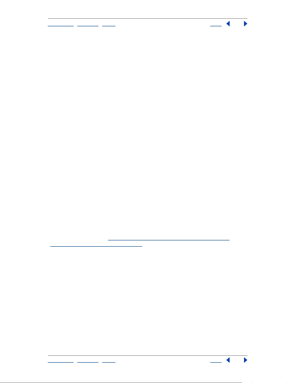
Adobe After Effects Help Channel effects
Using Help | Contents | Index Back 56
Swap Left-Right Swaps the left and right views.
3D View Specifies the rendering mode the effect uses to combine the views.
• Stereo Pair scales both layers to fit side by side within the effect layer’s bounding box.
Select Swap Left-Right to create cross-eyed vision. Selecting Stereo Pair disables
Convergence Offset.
• Interlace Upper L Lower R takes the upper (first) field from the Left View layer, and the
lower (second) field from the Right View layer, and combines them into a single or a
sequence of interlaced frames. Use this option if you want to view the results with
polarized or LCD shutter glasses. Select Swap Left-Right to switch fields.
• Red Green LR tints the Right View layer red, and the Left View layer green using the
luminance values of each layer.
• Red Blue LR tints the Right View layer red and the Left View layer blue using the
luminance values of each layer.
• Balanced Red Green LR performs the same operation as Red Green LR but also balances
the colors to reduce shadows or ghosting effects caused by one view showing through
the other. Setting a high value reduces the overall contrast.
• Balanced Red Blue LR performs the same operation as Red Blue LR but also balances the
colors in order to reduce shadows or ghosting effects.
• Balanced Colored Red Blue converts the layer into a 3D view using the original layer’s
RGB channels. This option maintains the layer’s original colors but may produce
shadows and ghosting effects. To reduce these effects adjust the balance, or desaturate
the image, and then apply 3D Glasses. If you are using CG images, raise the black level
of both views before applying the effect.
Balance Specifies the level of balance in a balanced 3D view option. Use this control to
reduce shadows and ghost effects. The default balance that 3D Glasses sets when you
select the Balanced Colored Red Blue option is the ideal value: If you set Balance to 0.0, 3D
Glasses creates no 3D depth, and if you set Balance too high, 3D Glasses produces a highly
saturated output.
For more information, see “Understanding red, blue, and green lenses” on page 56 and
“Understanding ghost effects” on page 56.
Understanding red, blue, and green lenses
When you work with red and blue images, the blue color in glasses with red and blue
lenses is actually cyan, not blue. Red and cyan are complementary colors, producing the
best separation because they filter each other out more efficiently. When you work with
red and green images, it may appear that the green is not as bright as the red. However,
viewing the images with red and green lenses produces an even result because green has
a higher luminance value than red.
Understanding ghost effects
Ghost effects occur when the luminance values of one color exceed those of another color
to such an extent that you can see the first color through the wrong lens of anaglyph
glasses. For example, an excessive red luminance value becomes visible through the blue
lens. If you adjust the Balance value, test the results on the final output media. If you set
the Balance value too high, a reversed shadow may appear.
Using Help | Contents | Index Back 56
Page 57

Adobe After Effects Help Channel effects
Using Help | Contents | Index Back 57
Alpha Levels (Pro only)
The Alpha Levels effect increases or decreases the transparency of a matte. Use Alpha
Levels to adjust pure black or pure white areas of a matte to be semitransparent, or to
adjust grays (semitransparent areas) to be pure black and white. Alpha values are
converted using Input limits, Output limits, and the Gamma value.
Original (left) and effect applied to arches layer with Input Black Level set to 144 and Output White
Level set to 90 (center), and with Output Black Level set to about 120 and Output White Level set to
0 (right)
Adjust the following controls for the Alpha Levels effect:
Input limits, Output limits Specify where transparency begins and ends.
Gamma Affects the range of gray values that are converted. A Gamma value of 1
produces a gradual (linear) distribution of gray values. A Gamma value of less than 1
creates darker gray values and more transparency. A gamma value of greater than 1
creates lighter gray values and less transparency.
To convert grays in the matte to pure black or white:
1 Set the Input Black Level to a gray value. Alpha values at this level or lower become fully
transparent (black).
2 Set the Input White Level to a gray value. Alpha values at this level or higher become
fully opaque (white).
3 Leave the Output Black Level set to 0 and the Output White Level set to 255.
4 If necessary, adjust the Gamma value to increase or decrease transparency.
To convert pure black and white in the matte into gray areas:
1 Leave the Input Black Level at 0 and the Input White Level at 255.
2 Set the Output Black Level slider to a gray value. Alpha values below this value rise to
this value.
3 Set the Output White Level to a gray value. Alpha values above this value are lowered to
this value.
Using Help | Contents | Index Back 57
Page 58

Adobe After Effects Help Channel effects
Using Help | Contents | Index Back 58
Arithmetic
The Arithmetic effect performs various simple mathematical operations on an image’s red,
green, and blue channels. Operator specifies the mathematical operation to perform
between the value you specify for each channel and the existing value of that channel for
each pixel in the image: And, Or, and Xor apply bitwise logical combinations of the
specified value; Add, Subtract, and Difference apply basic math functions using the
specified value; Max and Min select each pixel in the color channel that is respectively less
or greater than the specified value and set it at the specified value. Block Above and Block
Below turn the channel off everywhere that it is respectively greater or less than the
specified value; Slice turns the channel off where it is below the value specified and turns
it on where it is above the specified value.
Clip Result Values prevents all functions from creating color values that exceed the valid
range. If this option is not selected, some color values may wrap around from on to off, or
vice versa.
Original (left), with Operator set to Multiply and Red Value set to 255 (center), and with Operator set
to And and an increased Green Value (right)
Blend
The Blend effect blends two layers using one of five modes. A crossfade is a standard
transition between two images: the original image fades out while the new image fades
in.
Original (left), with layers blended using Darken Only Mode and Blend With Original set to 0%
(center), and with Color Only Mode and Blend With Original set to 50% (right)
Note: You can create blends more easily and quickly using layer modes, but you can’t
animate layer modes. The advantage of using the Blend effect is that you can animate it.
Blend controls
Adjust the following controls for the Blend effect:
Blend with Layer Specifies the layer to be blended with the original layer.
Using Help | Contents | Index Back 58
Page 59

Adobe After Effects Help Channel effects
Using Help | Contents | Index Back 59
Mode Specifies the Blend mode you want to use. Crossfade fades between the original
image and the secondary image. Color Only colorizes each pixel in the original image
based on the color of each corresponding pixel in the secondary image. Tint Only is similar
to Color Only but tints pixels in the original image only if they are already colored. Darken
Only darkens each pixel in the original image that is lighter than the corresponding pixel
in the secondary image. Lighten Only lightens each pixel in the original image that is
darker than the corresponding pixel in the secondary image.
Blend with Original Specifies the fading level between the blended image and the
original image. A setting of 0% shows only the secondary layer (or just the layers specified
with Blend if you are in Crossfade mode). At 100%, only the first layer is visible. Changing
this slider linearly over time gives you a standard crossfade. To try the other blending
modes, set Blend with Original to 0% to see the full effect of each mode.
Note: You can create a crossfade without applying an effect by animating the Opacity
property of one layer on top of another. However, this doesn’t work if the frontmost layer
has any transparent portions (which allows the other layer to show through, even when at
full opacity). The Crossfade mode creates a proper crossfade between two layers, even if
both have transparent regions.
If Layer Sizes Differ Specifies how to position the layers. The layer’s quality setting affects
Blend only if Stretch to Fit is selected and if the layers are of different sizes. Stretching at
Best quality is much smoother.
Using the Blend effect
The following procedure provides a basic overview of how to use this effect.
To use the Blend effect:
1 Make sure that the two source items to blend have been added to your composition.
2 Apply the Blend effect to one layer (A), and choose the name of the other layer (B) in the
Blend with Layer pop-up menu.
3 Hide layer B by clicking the Video switch next to the layer in the Audio/Video Features
column in the Timeline window.
Calculations
The Calculations effect combines the channels of one image with the channels of another.
Use this effect to quickly and easily produce some of the same results as you get from the
Shift Channels effect, the Compound Arithmetic effect, and precomposing.
Original layers (left and center) and with effect applied to arch layer with Input Channel set to Gray,
Second Source set to cloud layer, and Invert Second Layer selected (right)
Adjust the following controls for the Calculations effect:
Using Help | Contents | Index Back 59
Page 60

Adobe After Effects Help Channel effects
Using Help | Contents | Index Back 60
Input Channel Specifies the channel to extract and blend with the original layer. RGBA
displays all channels normally. Gray shows the luminance of the original RGBA image. Red,
Green, Blue, or Alpha converts all channels to the value of the specified channel.
Invert Input Inverts the layer before the effect extracts the specified channel information.
Second Layer Specifies the layer with which Calculations blends the original layer.
Second Layer Channel Specifies the channel to be blended with the input channels.
Second Layer Opacity Specifies the transparency of the second layer.
Invert Second Layer Inverts the second layer before the effect extracts the specified
channel information and calculates the blend.
Stretch Second Layer to Fit Stretches the second layer’s edges to the original layer’s
edges before blending. If you don’t select this control, the Calculations effect centers the
second source layer in the original layer and crops it to fit the effect layer’s boundaries.
Blending Mode Specifies the blend mode used for the blend of the original layer and
second layer
Preserve Transparency Ensures that the effect layer’s alpha channel is not modified.
.
Channel Combiner
The Channel Combiner effect extracts, displays, and adjusts various channels in your
image.
Original (left); with effect applied to cloud layer, Source Layer set to arch layer, From set to HLS to
RGB, and To set to Lightness (center); and with From set to Red, and To set to Lightness (right)
Channel Combiner controls
Adjust the following controls for the Channel Combiner effect:
Use 2nd Layer Specifies that the effect uses another layer to retrieve values from.
Source Layer Specifies which layer you want to retrieve values from. This layer must be in
the current composition but does not need to be visible.
From Specifies how you want to select values from the source layer. Most are self-explanatory; those that aren’t are as follows:
• RGB to YUV, YUV to RGB. YUV colorspace is used in component video. YUV represents
the Luminance in the Green values, the Luminance Difference between the Red and the
Green values, and the difference between the Blue and Green values.
• Straight to Premultiplied converts the alpha channel from Straight to Premultiplied
alpha, adding the transparency information to each of the visible RGB channels.
Using Help | Contents | Index Back 60
Page 61

Adobe After Effects Help Channel effects
Using Help | Contents | Index Back 61
• Saturation Multiplied specifies that the saturation value (including lightness) of an
image is the source. This option represents the most common view of a pixel’s
saturation value. Saturation is multiplied by the minimum distance to black or white
(lightness). For example, a dark or light blue pixel has less saturation than a bright or
“pure” blue pixel.
• Min RGB and Max RGB specify that the lowest or highest value of the red, green, and
blue channels of an image is the source.
To Specifies where the From values are applied. Some options, such as RGB to HLS, do not
use a To selection. Use Red Only, Green Only, and Blue Only to view selected RGB, HLS,
alpha, or luminance values in one channel without interference from the others. When you
select Hue Only, Lightness Only, or Saturation Only, the applied hue value is combined
with 50% lightness and 100% saturation; the applied lightness value is combined with 0%
saturation, which then gives the hue no effect; and the applied saturation values are
combined with 0% hue and 50% lightness.
Invert Inverts the values for the selected From and To options.
Solid Alpha Creates an opaque alpha channel throughout the layer, replacing the
original alpha channel.
Cineon Converter
The Cineon Converter effect provides a high degree of control over color conversions of
Cineon frames. In After Effects, you can convert the color in a Cineon file using controls in
the Interpret Footage dialog box or using the Cineon Converter effect. To use the Cineon
Converter effect, import a Cineon file and leave it in its default state; After Effects either
condenses the colors to 8 bit or expands them to 16 bit, depending on the mode you are
working in. You can then apply the Cineon Converter effect to the file and precisely adjust
the colors while interactively viewing the results in the Composition window. Set
keyframes to adjust for changes in tone over time—use keyframe interpolation and ease
handles to precisely match the most irregular lighting changes, or leave the file in its
default state and use the converter.
The 10 bits of data available in each Cineon channel make it easier to enhance an
important range of tones while preserving overall tonal balance. By carefully specifying
the range, you can create a version of the image that faithfully resembles the original.
Cineon Converter controls
Adjust the following controls for the Cineon Converter effect:
Conversion Type Specifies how the Cineon file is converted. Log to Linear converts an 8bit logarithmic non-Cineon layer that you plan to render as a Cineon sequence. Linear to
Log converts a layer containing an 8-bit linear proxy of a Cineon file into an 8-bit
logarithmic file so that its display characteristics are consistent with the original Cineon
file. Log to Log detects an 8- or 10-bit logarithmic Cineon file when you plan to render it as
an 8-bit logarithmic proxy.
Note: Obsolete versions of each option are available for compatibility with projects
converted from earlier versions of After Effects.
10 Bit Black Point Specifies the black point (minimum density) for converting a 10-bit
logarithmic Cineon layer.
Using Help | Contents | Index Back 61
Page 62

Adobe After Effects Help Channel effects
Using Help | Contents | Index Back 62
Internal Black Point Specifies the black point used for the layer in After Effects.
10 Bit White Point Specifies the white point (maximum density) for converting a 10-bit
logarithmic Cineon layer.
Internal White Point Specifies the white point used for the layer in After Effects.
Gamma Specifies the value of midtones.
Highlight Rolloff Specifies the rolloff value used to correct bright highlights.
Controlling the tonal balance of a Cineon file
The following procedure provides a basic overview of how to control the tonal balance of
a Cineon file.
To control the tonal balance of a Cineon file:
1 Import the Cineon file into After Effects, and add it to a composition.
2 Select the Cineon file layer in the Composition or Timeline window, and choose Effect >
Cineon Tools > Cineon Converter.
3 Choose an option from the Conversion Type menu.
4 Adjust the black point by dragging the 10 Bit Black Point slider right or left.
5 Adjust the white point by dragging the 10 Bit White Point slider left or right. (If
adjusting the brightest areas makes the rest of the image appear too dark, use the
Highlight Rolloff slider to adjust these bright highlights.)
6 Adjust midtones by dragging the Gamma slider to the left to darken midtones, or to the
right to lighten midtones.
7 If highlights appear as white blotches, drag the Highlight Rolloff slider to the right until
details are visible. An image with high contrast may require a high rolloff value.
Note: Each computer monitor has unique display characteristics that affect your
perception of color on-screen. For best results when evaluating tonal balance, use the Info
palette in After Effects to see the true color values of pixels as you move the pointer over
them.
Compound Arithmetic
The Compound Arithmetic effect mathematically combines the layer to which it is applied
with another layer. The Compound Arithmetic effect is intended only to provide compati
bility with projects created in earlier versions of After Effects that use the Compound
Arithmetic effect. Using layer modes is usually more effective than using the Compound
Arithmetic effect.
-
Original (left); with effect applied to arch layer, Operator set to Difference, Operate on Channels set
to RGB, and Blend with Original set to 8% (center); and with Second Source set to cloud layer,
Operator set to And, Operate on Channels set to RGB, and Blend with Original set to 50% (right).
Using Help | Contents | Index Back 62
Page 63

Adobe After Effects Help Channel effects
Using Help | Contents | Index Back 63
Adjust the following controls for the Compound Arithmetic effect:
Second Source Layer Specifies the layer to use with the current layer in the given
operation.
Operator Specifies the operation to perform between the two layers.
Operate on Channels Specifies the channels to which the effect is applied.
Overflow Behavior Specifies how pixel values that exceed the allowed range are treated.
Clip indicates that the values are limited to the allowed range. Wrap indicates that values
exceeding the allowed range wrap around from full on to full off, and vice versa. Scale
indicates that the maximum and minimum values are calculated and the results are
stretched down from that full range to the range of allowable values.
Stretch Second Source to Fit Scales the second layer to match the size (width and
height) of the current layer. If this option is deselected, the second layer is placed at its
source’s current size, aligned with the upper left corner of the source layer.
Blend with Original Adjusts the opacity of the second source layer so it blends with the
original layer.
Invert
The Invert effect inverts the color information of an image.
Original (left) and with effect applied to cloud layer with Channel set to Luminance (center) and Blue
(right)
Adjust the following controls for the Invert effect:
Channel Specifies which channel or channels to invert. Each group of items operates in a
particular color space, inverting either the entire image in that color space or just a single
channel. RGB consists of three additive color channels: red, green, and blue. HLS consists
of three calculated color channels: hue, lightness, and saturation. YIQ is the NTSC
luminance and chrominance color space, where Y is the luminance signal, and I and Q are
the inphase and quadrature chrominance signals. Alpha (not a color space) provides a way
to invert the alpha channel of the image.
Blend with Original Combines the inverted image with the original. You can apply a fade
to the inverted image.
Using Help | Contents | Index Back 63
Page 64

Adobe After Effects Help Channel effects
Using Help | Contents | Index Back 64
Minimax
The Minimax effect enlarges or reduces a matte for a specific channel or all channels. It
assigns each pixel the minimum or maximum pixel value found within a specified radius.
For example, a white solid layer with a square mask shrinks one pixel on each side using
Minimum and a radius of 1. The layer’s quality setting does not affect Minimax.
Original (left); with Operation set to Maximum, Channel set to Green, and Direction set to Vertical
(center); Operation set to Maximum Then Minimum, Radius set to a low value, and Channel set to
Color (right)
Adjust the following controls for the Minimax effect:
Operation Specifies how the effect processes the matte. Minimum replaces a pixel with
the smallest pixel value within the radius specified, and Maximum replaces a pixel with the
largest pixel value within the radius specified. Minimum Then Maximum performs the
Minimum operation on the layer followed by the Maximum operation using the Radius
setting, and Maximum Then Minimum does the opposite.
Radius Specifies how many pixels to examine for the Minimum or Maximum operation.
Channel Specifies the channel. Color affects the color channels only. Alpha and Color
affects all channels. Red, Green, Blue, and Alpha affect only the respective channels.
Direction Specifies the direction of scanning for values. Horizontal & Vertical scans all
directions for the minimum or maximum pixel. Just Horizontal and Just Vertical scan only
left and right or up and down, respectively.
Remove Color Matting
The Remove Color Matting effect removes color fringes from layers that are premultiplied
with a color. It is useful when merging alpha and fill from separate files. If you import
footage with a premultiplied alpha channel or if you create alpha channels with After
Effects, you may need to remove halos from an image. Halos are caused by a large contrast
between the image’s color and the background, or matte, color. Removing or changing
the color of the matte can remove the halos. (Halos can also be caused by a misinterpre
tation of an alpha channel’s premultiplied color.)
-
Using Help | Contents | Index Back 64
Page 65

Adobe After Effects Help Channel effects
Using Help | Contents | Index Back 65
Use Background Color to specify the new background color when you want to change the
color of a matte.
Original premultiplied with black (left), the black halo (center), and after applying the Remove Color
Matting effect to remove the halo (right)
Use this effect in conjunction with other effects that let you create alpha channels, to
achieve more control over the appearance of the alpha channel.
Original (left); with Channel Shift effect applied to create alpha channel from the red channel
(center); and with Remove Color Matting applied twice: once with cyan selected, once with yellow
selected (right)
Set Channels
The Set Channels effect copies channels from other layers to the red, green, blue, and
alpha channels of the current layer. For example, you can take the luminance of one layer
and put it into the color channel of the selected layer. All source layers are centered in the
current layer. With Best quality selected, any stretched layers are anti-aliased.
Use Stretch Layers to Fit to resize all other layers to the size of the layer to which Set
Channels is being applied.
Original (left); with effect applied to arches layer with Source Layer 1 set to cloud layer and Set Red
To Source 1’s Red (center); and with Set Red To Source 1’s Green, Set Green To Source 1’s Blue, and
Set Blue To Source 1’s Red. (right)
Using Help | Contents | Index Back 65
Page 66
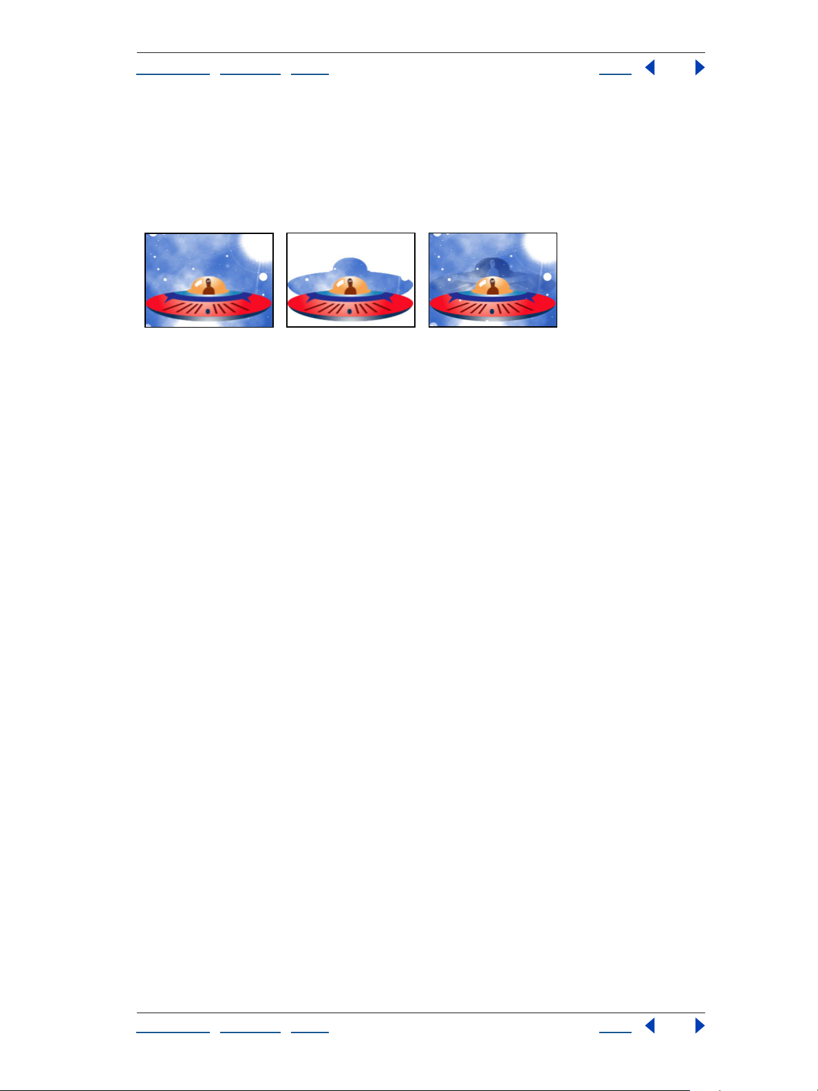
Adobe After Effects Help Channel effects
Using Help | Contents | Index Back 66
Set Matte
The Set Matte effect replaces the alpha channel (matte) of a layer with a channel from
another layer above it for the creation of traveling matte effects.The Set Matte effect is
intended only to provide compatibility with projects created in earlier versions of After
Effects that use the Set Matte effect.
Original (left) and with saucer used as a matte on the cloud layer (center) and the luminance of the
saucer layer used as a matte (right)
To create a traveling matte using the Set Matte effect, set up the motion of the matte layer
and precompose that layer with all properties. Use the resulting composition as the layer
from which to take the matte. Although you can use Set Matte for a traveling matte, it is
easier and faster to create traveling mattes by using a track matte.
Adjust the following controls for the Set Matte effect:
Take Matte From Layer Specifies the layer to use as the replacement matte. You can
specify any layer in the composition.
Use for Matte Specifies the channel of the specified layer to use for the matte.
Invert Matte Inverts the transparency values of the matte.
Stretch Matte to Fit Scales the selected layer to match the size of the current layer. If
Stretch Matte to Fit is deselected, the layer designated as the matte is centered in the first
layer.
Composite Matte with Original Composites the new matte with the current layer, rather
than replacing it. The resulting matte allows the image to show through only where the
current matte and the new matte both have some opacity.
Premultiply Matte Layer Premultiplies the new matte layer with the current layer.
Using Help | Contents | Index Back 66
Page 67
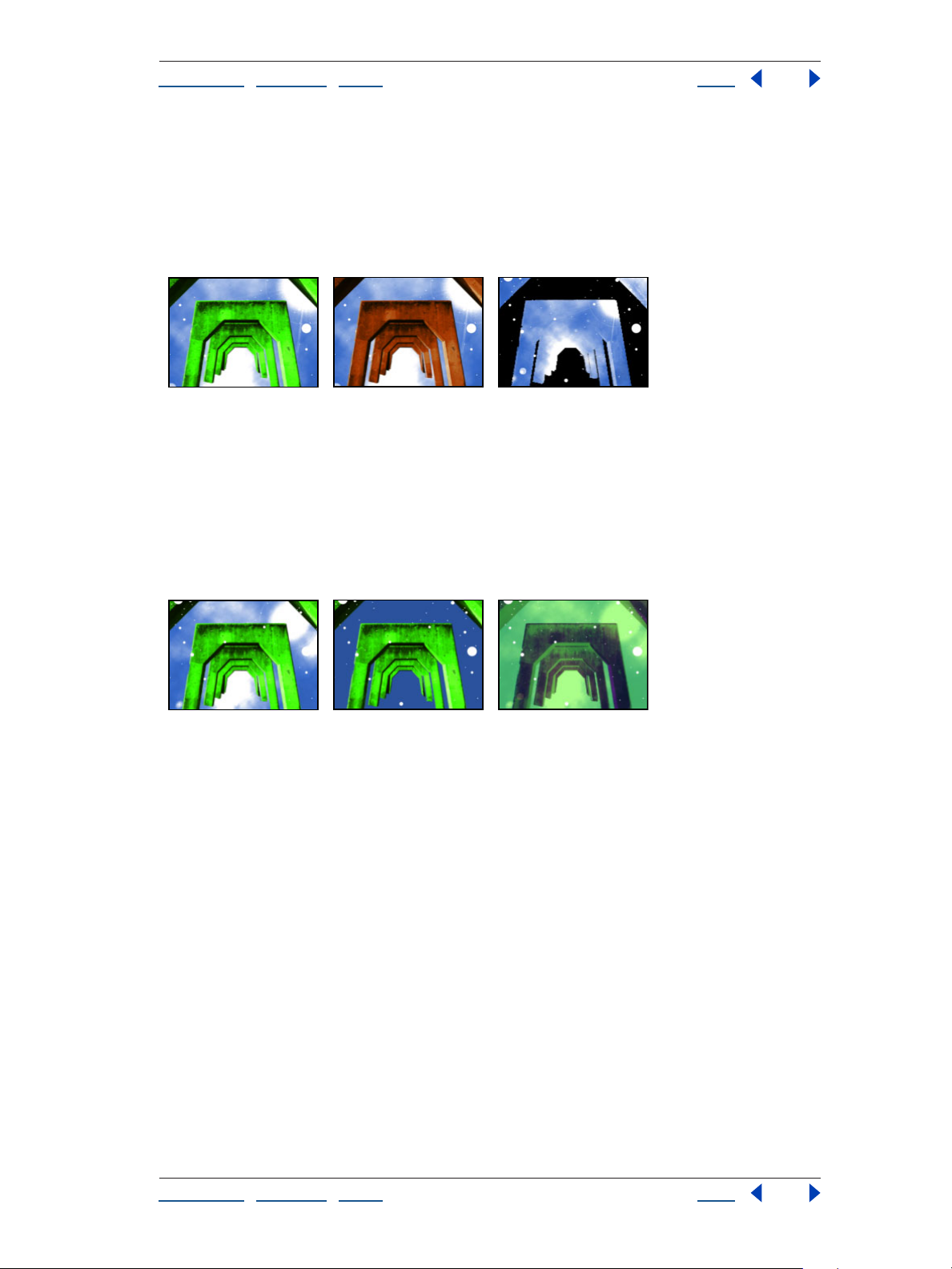
Adobe After Effects Help Channel effects
Using Help | Contents | Index Back 67
Shift Channels
The Shift Channels effect replaces red, green, blue, and alpha channels in the image with
other channels. In Take
Note: You can use this effect to display the alpha channel for a layer if you set the RGB
channels to Alpha and set the alpha channel to Full.
Original (left); with Take Alpha From set to Blue and Take Red, Green, and Blue set to Alpha (center);
and with Take Alpha From set to Alpha, Take Red From set to Green, Take Green From set to Lightness,
and Take Blue From set to Full Off (right)
channel From, specify which channel to use as a source.
Solid Composite
The Solid Composite effect offers a quick way to create a composite of a new color solid
behind the original source layer. You can control the opacity of the source layer, control
the opacity of the solid, and apply blend modes all within the effect’s controls.
Original (left); with Source Opacity and Opacity set to 50% and Blending Mode set to Difference
(center); and Source Opacity and Opacity set to 100%, Color sampled from cloud layer, and Blending
Mode set to Normal (right)
Adjust the following controls for the Solid Composite effect:
Source Opacity Specifies the transparency of the source layer.
Color Specifies the color of the new solid.
Opacity Specifies the transparency of the solid.
Blending Mode Specifies the blend mode the effect uses to combine the original layer
and the new solid. These blend modes behave exactly like those in the Timeline window.
Using Help | Contents | Index Back 67
Page 68
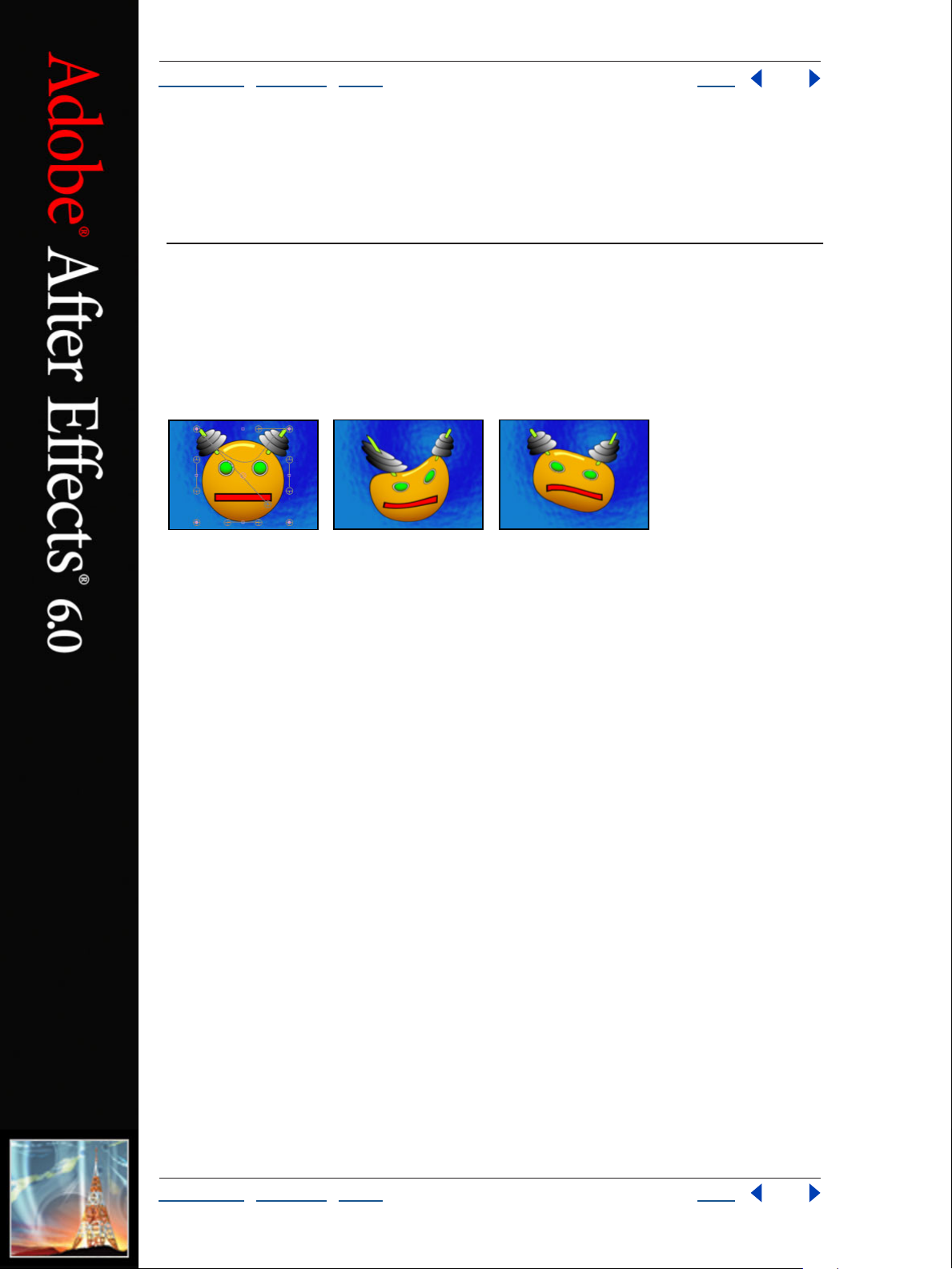
Adobe After Effects Help Distort effects
Using Help | Contents | Index Back 68
Distort effects
Bezier Warp (Pro only)
The Bezier Warp effect shapes an image using a closed Bezier curve along the boundary of
a layer. The curve consists of four segments. Each segment has four control points (two
vertices and two tangents). The vertices control the position of the segments, and the
tangents control the curvature of the segments.
Original (left) and with variations of Bezier Warp applied (center and right)
The positions of vertices and tangents determine the size and shape of a curved segment.
Dragging these points reshapes the curves that form the edge, thus distorting the image.
For example, you can use Bezier Warp to reshape one image to fit another, as in wrapping
a label around a jar. Bezier Warp is also useful for correcting lens aberrations, such as the
fish-eye effect (barrel distortion) that can occur when using a wide-angle lens. Using
Bezier Warp, you can bend the image back to achieve an undistorted look. By animating
the effect and choosing a high quality setting, you can create fluid visual effects, such as a
jiggling gelatin dessert or a fluttering flag.
Bezier Warp controls
Adjust the following controls for the Bezier Warp effect:
Top Left Vertex Specifies the starting vertex for the top segment or the ending vertex for
the left segment.
Top Left Tangent, Top Right Tangent Specify the starting and ending tangents for the
top segment.
Right Top Vertex Specifies the ending vertex for the top segment or the starting vertex
for the right segment.
Right Top Tangent, Right Bottom Tangent Specify the starting and ending tangents for
the right segment.
Bottom Right Vertex Specifies the ending vertex for the right segment or the starting
vertex for the bottom segment.
Bottom Right Tangent, Bottom Left Tangent Specify the ending and starting tangents
for the bottom segment.
Left Bottom Vertex Specifies the ending vertex for the bottom segment or the starting
vertex for the left segment.
Using Help | Contents | Index Back 68
Page 69
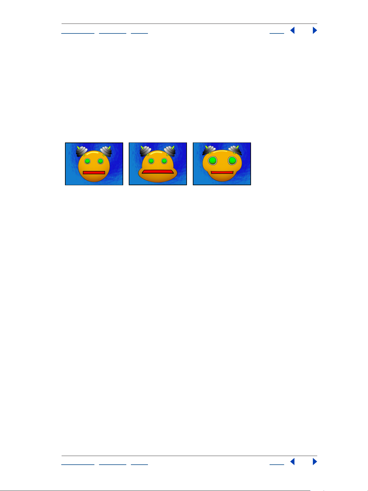
Adobe After Effects Help Distort effects
Using Help | Contents | Index Back 69
Left Bottom Tangent, Left Top Tangent Specify the ending and starting tangents for
the left segment.
Quality Specifies how closely the image follows the shape defined by the curve. The
higher the quality value, the more closely the image follows the shape. Higher quality
settings require more rendering time.
Bulge (Pro only)
The Bulge effect distorts an image around a specified point, making the image appear to
bulge toward or away from the viewer, depending on the options you select.
Original (left) and with variations of Bulge applied (center and right)
Adjust the following controls for the Bulge effect:
Horizontal Radius Sets the width of the bulge, measured in pixels. You can also set the
radius values by dragging the selection handles in the layer.
Vertical Radius Sets the length of the bulge, measured in pixels. You can also set the
radius values by dragging the selection handles in the layer.
Bulge Center Sets the center point from which the bulge is created.
Bulge Height Sets the depth of the bulge. Positive values push the bulge toward the
viewer. Negative values pull the bulge away from the viewer. A bulge height of 0 produces
no bulge, which can be useful for setting keyframes so the bulge fades in over time.
Taper Radius Sets the steepness of the sides of the bulge. A taper radius of 0 produces a
steep, pronounced bulge. Increasing the taper radius produces a more gradual bulge.
Antialiasing Sets the amount of edge smoothing (blending of colors) at the boundaries
of the bulge. Anti-aliasing is applied only when Best quality is selected for the layer. For
many layers, Low produces satisfactory results. High produces more smoothing but can
significantly increase rendering time.
Pin All Edges Prevents the edges of the layer from bulging.
Using Help | Contents | Index Back 69
Page 70
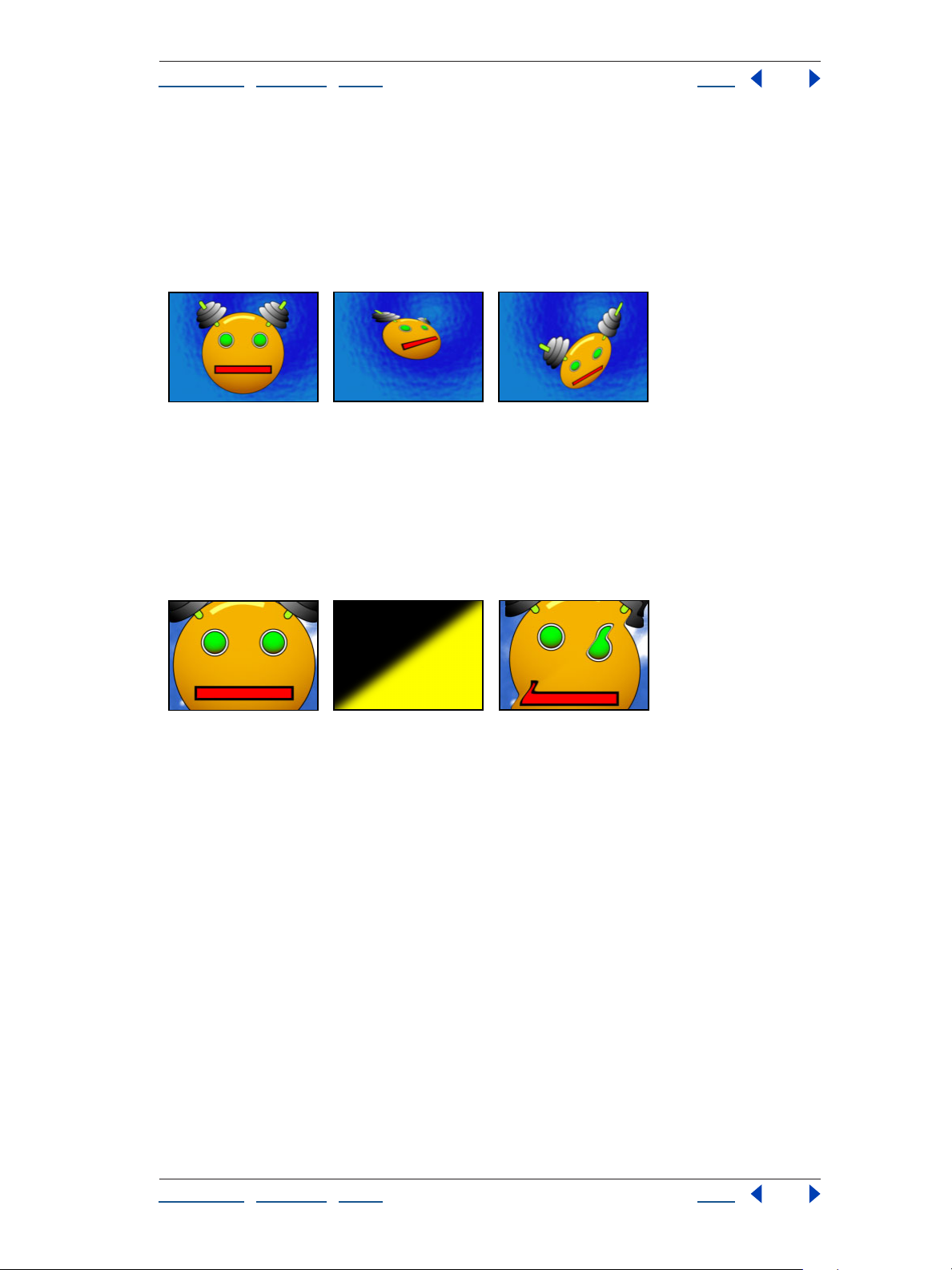
Adobe After Effects Help Distort effects
Using Help | Contents | Index Back 70
Corner Pin (Pro only)
The Corner Pin effect distorts an image by repositioning each of its four corners. Use it to
stretch, shrink, skew, or twist an image or to simulate perspective or movement that pivots
from the edge of a layer, such as a door opening. You can also use it to attach a layer to a
moving rectangular region tracked by the Motion Tracker. You can move the corner pins in
the Composition window or the Effect Controls window.
Original (left) and with two variations of Corner Pin applied (center and right)
Displacement Map (Pro only)
The Displacement Map effect distorts a layer by displacing pixels horizontally and vertically based on the color values of pixels in a second layer, called the displacement map. The
type of distortion created by the Displacement Map effect can vary greatly, depending on
the displacement map and options you select.
Original (left), Displacement map (center) and displaced image (right)
The displacement is determined from the color values of the displacement map. The color
values range from 0 to 255. Each value is converted into a scale ranging from -1 to 1. The
displacement amount is calculated by multiplying the converted value by the maximum
displacement amount you specify. A color value of 0 produces maximum negative
displacement (–1 maximum displacement). A color value of 255 produces maximum
positive displacement. A color value of 128 produces no displacement. For other values,
you can calculate the displacement amount, in pixels, using the following equation:
Displacement amount = maximum_displacement * (2 * (color value – 128)/256)
To displace an image:
1 Select the layer, and choose Effect > Distort > Displacement Map.
2 In the Effect Controls window, choose the layer to use as the displacement map from
the Displacement Map Layer pop-up menu. After Effects uses the layer in its original form,
without any masking, effects, or transformations you may have applied. If you want to
include those alterations, precompose that layer using the Move All Attributes Into the
New Composition option.
3 Choose the channel to use for horizontal displacement and vertical displacement, and
enter a maximum displacement value for each in the Effect Controls window.
Using Help | Contents | Index Back 70
Page 71

Adobe After Effects Help Distort effects
Using Help | Contents | Index Back 71
4 Choose a behavior from the Displacement Map Behavior pop-up menu:
• Center Map overlays the displacement map over the layer.
• Stretch Map to Fit resizes the displacement map to the layer’s size.
• Tile Map fills the layer with as many copies of the map as can fit.
5 In Edge Behavior deselect Wrap Pixels Around to halt the displacement at the edge of
the image.
Liquify
The Liquify effect lets you push, pull, rotate, enlarge and shrink areas in a layer. Several
Liquify tools distort the brush area when you hold down the mouse button or drag. The
distortion is concentrated at the center of the brush area, and the effect intensifies as you
hold down the mouse button or repeatedly drag over an area.
You can limit the area of a layer you distort using Freeze Area Mask. Use the Reconstruction mode to lessen or undo distortions you’ve created.
Original (left) and with variations of Liquify applied (center and right)
Setting Mask Properties
The Liquify effect uses the mask properties to determine how to affect the image. Use
Freeze Area Mask, Mask Opacity, and Mask Feather settings to control the Liquify effect:
Freeze Area Mask determines the area of the image in which the distortion is affected by
mask opacity and feather settings. Areas outside the mask are distorted; areas within the
mask are distorted according to the mask opacity and feather settings.
Mask Opacity determines how the area within the mask is affected by the distortion.
When Mask Opacity is set to 100%, the area within the mask is not affected by the
distortion; when it’s set to 50%, the area within the mask is somewhat affected. If you set
the opacity to 100%, make sure to feather the mask to prevent jagged edges on the mask.
Mask Feather determines the pixels at the borders of the mask used to blend the
masked area into the non-masked areas. You can begin with a feather value of 10 pixels
and then adjust it as appropriate.
Using the Liquify tools
The Liquify tools offer several ways to distort the image:
Warp pushes pixels forward as you drag.
Turbulence smoothly scrambles pixels. It is useful for creating fire, clouds, waves, and
similar effects.
Twirl clockwise rotates pixels clockwise as you hold down the mouse button or drag.
Using Help | Contents | Index Back 71
Page 72
Adobe After Effects Help Distort effects
Using Help | Contents | Index Back 72
Twirl counterclockwise rotates pixels counterclockwise as you hold down the mouse
button or drag.
Pucker moves pixels toward the center of the brush area as you hold down the mouse
button or drag.
Bloat moves pixels away from the center of the brush area as you hold down the
mouse button or drag.
Shift pixels moves pixels perpendicular to the stroke direction.
Reflection copies pixels to the brush area.
Clone copies the distortions from around a source location to the current mouse
location. Select the source location by Alt-clicking (Windows) or Option-clicking (Mac OS)
the source point.
Reconstruction reverses distortions or applies them in different ways.
Distorting an image
The following procedure provides a basic overview of how to use the Liquify effect.
To distort an image:
1 Select the layer, and choose Effect > Distort > Liquify.
2 In the Layer window, create a mask to freeze areas of the image and then set mask
properties. See
3 In the Effect Controls window do the following:
• Choose the mask you created from the Freeze Area Mask pop-up menu.
• Specify a brush size and brush pressure. A low brush pressure makes changes occur
more slowly, so it’s easier to stop them at exactly the right moment.
“Setting Mask Properties” on page 71
• Specify a turbulent jitter to control how tightly the turbulence tool scrambles pixels.
• Select View Mesh under the View Options control.
• Set a distortion mesh offset if desired.
• Drag the Distortion Percentage slider to specify the amount of distortion.
4 Use the tools to distort the preview of the image. (See “Using the Liquify tools” on
page 71.)
5 Use the reconstruct tool to fully or partially reverse the distortions or to change the
image in new ways. (See “Reconstructing distortions” on page 72.)
Reconstructing distortions
Use the reconstruction tool and its modes to reverse distortions or redo them in new ways.
To restore a preview image to a previous state:
1 Select the reconstruction tool, and then choose a mode from the Reconstruction Mode
pop-up menu:
• Revert changes unfrozen areas back to their predistorted state.
• Displace reconstructs unfrozen areas to match the displacement at the starting point
for the reconstruction. You can use Displace to move all or part of the preview image to
a different location.
Using Help | Contents | Index Back 72
Page 73

Adobe After Effects Help Distort effects
Using Help | Contents | Index Back 73
• Amplitwist reconstructs unfrozen areas to match the displacement, rotation, and
overall scaling that exist at the starting point.
• Affine reconstructs unfrozen areas to match all local distortions that exist at the starting
point, including displacement, rotation, horizontal and vertical scaling, and skew.
2 Drag the area to restore. The restoration occurs more quickly at the brush center.
Magnify
The Magnify effect enlarges a selected area of a layer. This effect can act like a magnifying
glass placed over an area of the image, or you can use it to scale the entire image far
beyond 100% while maintaining resolution.
Original (left) and with variations of Magnify applied (center and right)
Magnify controls
Adjust the following controls for the Magnify effect:
Shape Specifies the shape of the magnified area.
Center Specifies the center point of the magnified area.
Magnification Specifies the percentage of magnification (or scale) of the area you select.
The values represent the percentage of the scale.
Link Specifies how the effect links the Size, Magnification, and Feather amounts so that
they increase or decrease proportionally. None specifies that the Size, Magnification, and
Feather controls operate separately. Size To Magnification specifies that the size of the
magnified area increases or decreases proportionally in relation to the magnification
adjustment. Size & Feather To Magnification specifies that the size and edge feather of the
magnified area increase or decrease proportionally in relation to the magnification
adjustment. (Setting the Link control to any setting except None disables the Resize Layer
control.)
Size Specifies the size of the magnified area, in pixels. (Setting the size larger than your
original source layer may expand the magnified area outside the composition frame,
depending upon the location of your center point. However, the effect still retains the
image resolution.)
Feather Specifies the amount of feather, in pixels, that the effect applies to the edge of
the magnified area. Higher values soften the edge of the magnified area, and blends the
edge with the layer behind it. Lower values sharpen the edge of the magnified area.
Opacity Specifies the transparency of the magnified area. The Opacity value for the effect
layer in the Timeline window represents the 100% setting of this control.
Using Help | Contents | Index Back 73
Page 74

Adobe After Effects Help Distort effects
Using Help | Contents | Index Back 74
Scaling Specifies the type of scaling the effect uses to magnify a layer. Standard uses
standard scaling. This method maintains sharpness in the image but produces pixelated
edges at higher values. Soft uses spline algorithms. If you scale the image beyond 100%,
Soft reduces edge pixelation and maintains image quality. Soft works well at large magni
fication amounts. Scatter creates scatter or noise in the image as the image enlarges.
Blending Mode Specifies the blend mode that the effect uses to combine the magnified
area with the original layer. Except for None, all of these blend modes behave identically to
the Timeline window blend modes. The None option displays transparent pixels around
the magnified area.
Resize Layer If Resize Layer is selected, the effect uses only the composition boundaries
as the edge of the layer when the magnified area extends beyond the original layer’s
boundaries. If Resize Layer is deselected, any area of the image outside the original layer’s
bounding box is cropped by the layer’s boundaries.
Mesh Warp (Pro only)
The Mesh Warp effect applies a grid of Bezier patches (squares in the grid) over a layer,
which you can manipulate to distort areas of an image. Each corner of a patch includes a
vertex and two to four
makes up the edge of the patch). The number of tangents depends on whether the vertex
is in a corner, on an edge, or inside the grid. By moving the vertices and tangents, you can
manipulate the shape of the curved line segment. The finer the grid, the tighter the adjust
ments you can make to the area of the image inside the patch.
You can also use Mesh Warp to create smooth transitions between multiple images and
layers. Using keyframes for effects and opacity, you can animate the transition between
layers, revealing and distorting layers over time.
tangents (points that control the curvature of the line segment that
-
-
Original (left), with distortion mesh (center) and with Mesh Warp applied (right)
To select multiple verticies, Shift-click the verticies.
Adjust the following controls for the Mesh Warp effect:
Rows, Columns Specify up to 127 patches vertically (Rows) or horizontally (Columns). For
broader distortion, use fewer patches. For finer control, use more. Drag the vertices and
tangents to change the grid shape. The image follows the grid shape according to the
elasticity setting and the boundary created by the adjacent patch.
Quality Specifies how closely the image follows the shape defined by the curve. The
higher the quality value, the more closely the image follows the shape. Higher quality
settings require more rendering time.
Using Help | Contents | Index Back 74
Page 75

Adobe After Effects Help Distort effects
Using Help | Contents | Index Back 75
Distortion Mesh Click the stopwatch to animate the distortion over time.
Note: Each patch becomes a boundary for the distortion. For example, when you stretch a
patch, the area of the image in the patch stretches, squishing the area of the image in the
adjacent patch. The boundary of the adjacent patch protects the image inside it from
being squished to zero. In other words, you can’t push an image out of its patch.
Mirror
The Mirror effect splits the image along a line and reflects one side onto the other.
Reflection Center specifies the position of the line.Reflection Angle determines which side
is reflected and where the reflection appears. An angle of 0 degrees reflects the left side
onto the right. An angle of 180 degrees reflects the right side onto the left. An angle of 90
degrees reflects the top onto the bottom. An angle of 270 degrees reflects the bottom
onto the top. The layer’s quality setting influences the Mirror effect. At Best quality, the
reflected image is smoother and more accurate.
Original (left) and with variations of Mirror applied (center and right)
Offset
The Offset effect pans the image within a layer. Visual information pushed off one side
of
the image appears on the opposite side. At Best quality, the offset is performed with
subpixel
Shift Center To specifies the new position of the original image’s center point. Blend with
Original specifies the amount by which the offset image is blended with the original
image.
Original (left) and with variations of Offset applied (center and right)
precision.
Using Help | Contents | Index Back 75
Page 76

Adobe After Effects Help Distort effects
Using Help | Contents | Index Back 76
Optics Compensation (Pro only)
Use the Optics Compensation effect to add or remove camera lens distortion. Elements
composited with mismatched lens distortion cause anomalies in the animation. For
example, tracked objects in a distorted scene don’t match the scene area because linear
objects don’t follow the distortion of the scene.
Original (left) and with variations of Optics Compensation applied (center and right)
Optics Compensation controls
Adjust the following controls for the Optics Compensation effect:
Field of View (FOV) Specifies the field of view of the distorted footage. The FOV is
relative to the size of the source layer and the selected FOV Orientation. The distortion
amount is relative to FOV. There is no general rule as to what FOV value applies to different
lenses. Zooming in reduces the FOV, and zooming out increases it. Consequently, if
footage includes different zoom values you’ll need to keyframe the FOV value.
Reverse Lens Distortion Reverses the lens distortion. For example, to remove wideangle lens distortion, set Field of View to 40.0 and select Reverse Lens Distortion. Selecting
Reverse Lens Distortion enables the Resize control.
FOV Orientation Specifies the axis on which the Field of View value is based. This is
useful when matching computer-generated elements to the rendered view angle.
View Center Specifies an alternate center point of view. This is useful when using custom
lenses that are not centered. However, in most cases, this control should be left
untouched.
Optimal Pixels Maintains as much pixel information as possible through the distortion.
When selected, FOV values are no longer reversible.
Resize Resizes the layer when the applied distortion stretches the layer beyond its
boundaries. To use this control, first select Reverse Lens Distortion, and then choose an
option. Off does not resize the layer. Max 2X resizes the layer to a maximum of twice the
original width and height. Max 4X resizes the layer to a maximum of four times the original
width and height. Unlimited resizes as far as the layer is stretched. This option may require
a large amount of memory.
Applying other effects while adjusting FOV
To match FOV values, layers must be the same size. However, if you select Resize, you can
apply Optics Compensation again and reverse the distortion using the same value
(reversed). You can then apply another effect between the two instances of Optics
Compensation.
If you resize a layer using Optics Compensation and then precompose it into a larger
composition, you cannot reverse the distortion using the same value until you enlarge the
precomposed layer to accommodate the expanded layer.
Using Help | Contents | Index Back 76
Page 77

Adobe After Effects Help Distort effects
Using Help | Contents | Index Back 77
Matching FOV with computer graphics
To determine the correct FOV, find an edge or line in the footage that is distorted. Adjust
the FOV until the edge is straight, and then apply the reverse of that value to computergenerated material. This process composites the computer-generated element with the
footage using a matching lens distortion.
To match computer graphics with a lens distortion:
1 Select the footage layer with the distortion, and choose Effect > Distort > Optics
Compensation.
2 In the Effect Controls window, adjust the FOV until a distorted edge or line appears
straight. Note the FOV value.
3 Select the computer graphic layer you want to distort, and apply Optics Compensation
to it using the FOV value from step 2.
4 Select Reverse Lens Distortion.
5 Remove Optics Compensation from the footage layer.
Polar Coordinates
The Polar Coordinates effect distorts a layer by transposing each pixel in the layer’s x,y
coordinate system to the corresponding position in the polar coordinate system, or the
reverse. This effect produces unusual and surprising distortions that can vary greatly
depending on the image and the controls you select. The standard coordinate system
specifies points by measuring the horizontal distance (
axis) from the origin. Each point is specified as (x,y). The polar coordinate system specifies
points by measuring the length of a radius from the origin (
(
θ). Each point is specified as (r, θ).
Original (left) and with variations of Polar Coordinates applied (center and right)
Adjust the following controls for the Polar Coordinates effect:
Interpolation Specifies the amount of distortion. At 0% there is no distortion.
Type of Conversion Specifies the conversion process to use. Choose one of the following
options:
x axis) and the vertical distance (y
r) and its angle from the x axis
• Rect to Polar moves pixels by using x,y coordinates from each pixel as r, θ coordinates.
For example, an
a degree of 3. Horizontal lines distort into circles, and vertical lines into radial lines.
• Polar to Rect moves pixels by using the r, θ coordinates from each pixel as the x,y coordi-
nates. For example, a polar coordinate of radius 10 and 45 degrees becomes an x,y
coordinate of 10,45.
Using Help | Contents | Index Back 77
x,y coordinate of 2,3 becomes a polar coordinate with a radius of 2 and
Page 78

Adobe After Effects Help Distort effects
Using Help | Contents | Index Back 78
Reshape (Pro only)
The Reshape effect transforms one shape into another shape on the same layer, dragging
the underlying image with it. The image is distorted to fit the shape of the new area. You
create or import up to three masks to define the area you want to distort: the source mask,
the destination mask, and the boundary mask (optional).
Original including three masks (left) and with variations of Reshape applied (center and right)
After Effects assigns the masks a function (source, destination, or boundary) based on the
order you create or import them. You can also specify different masks. You can create
masks in the Layer window in After Effects, or use masks created in Adobe Illustrator. Use a
closed path for each mask. All three masks must be on the same layer as the footage to
which you will apply the Reshape effect, although you can copy masks from another layer.
As with the Mesh Warp effect, you can use Reshape to create unusual transitions between
multiple images and layers. Using keyframes for effects and opacity, you can animate the
transition between layers, revealing and distorting layers over time.
Reshape controls
Adjust the following controls for the Reshape effect:
Source Mask Specifies the mask that contains the image area you want to reshape. If not
specified, After Effects uses the second mask created as the Source mask. In the Compo
sition and Layer windows, a red outline defines the source mask.
Destination Mask Specifies the mask that determines the shape of the final image. If not
specified, After Effects uses the third mask created as the Destination mask. In the Compo
sition and Layer windows, a yellow outline defines the destination mask.
Boundary Mask Specifies what part of the image is reshaped. Anything outside the
boundary is not altered. If not specified, After Effects uses the first mask created as the
Boundary mask. In the Composition and Layer windows, a blue outline defines the
boundary mask.
Percent Specifies the percent of the reshape. This value is useful for creating partial
distortions that grow over time.
Elasticity Specifies how closely the image follows the shape defined by the curve. Stiff
acts like cold rubber, allowing the image to distort the least amount. Super Fluid acts like
hot rubber, allowing the image to distort in a fluid fashion. The other settings fall between.
The more fluid elasticity settings require more rendering time. If the final image doesn’t
follow the curve as expected, use the following elasticity guidelines:
-
-
• In general, use the stiffest setting possible that doesn’t create a polygonal image. Use a
higher elasticity setting if the final image looks polygonal but the curves are smooth.
• Use Stiff, Less Stiff, or Below Normal if the source and destination masks are similar in
shape and have low curvature (few curved segments that change direction radically).
Using Help | Contents | Index Back 78
Page 79

Adobe After Effects Help Distort effects
Using Help | Contents | Index Back 79
• Use Normal, Absolutely Normal, or Above Average if the source and destination masks
are dissimilar and have mild curvature.
• Use Loose, Liquid, or Super Fluid if the masks are very dissimilar and have extreme
curvature.
Correspondence Points Specifies the number of points on the source mask that are
associated with, or mapped to, points on the destination mask. These points appear in the
Composition window and control the interpolation of the distortion through space. To
control the precision of the effect, you can add, delete, or move the points on either mask.
A mask can have an unlimited number of points, but the more points it has, the longer the
effect takes to render. If the distortion appears twisted, try adding more correspondence
points at distinguishing points along the masks. (If the arc lengths of the curves between
correspondence points are too different, twisting may result.)
Interpolation Method Specifies how After Effects determines the distortion of each
video or animation frame in the interval between keyframes or when no keyframes exist.
• Discrete requires no keyframes because it calculates the distortion at each frame.
Discrete produces the most accurate results but requires more rendering time.
• Linear (the default) requires two or more keyframes and performs a straight-line inter-
polation between the keyframes. Linear produces steady changes between keyframes
and sharp changes at keyframes.
• Smooth requires three or more keyframes and approximates the distortion using cubic
curves, producing distortions with graceful motion.
Using the Reshape effect
The following procedure provides a basic overview of how to use this effect.
To apply the Reshape effect:
1 Open the layer in a Layer window.
2 Create or import the source, destination, and boundary masks into the layer.
Name each mask so that you can easily recognize it in the Mask menu in the Effect
Controls window.
3 In the Timeline window, choose None from the Mode pop-up menu for each mask.
4 Position the boundary mask to specify the area of the image that will remain unaltered.
(Areas within the boundary mask will be distorted; areas outside the mask will remain
unaltered. Keep
nation masks to avoid foldovers.)
5 Scale and position the source mask over the image.
6 Scale and position the destination mask to indicate the final shape. (Distortions work
best if the source and destination masks are roughly in the same location.)
7 Make the Composition or Timeline window active, select the layer, and then choose
Effect > Distort > Reshape.
the boundary mask as far away as possible from the source and desti-
8 From the Mask menus, choose the source, destination, and boundary masks.
9 Adjust the Percent control, and choose an option for Elasticity.
10 In the Composition window, add, delete, or move correspondence points on the
masks to control the distortion:
Using Help | Contents | Index Back 79
Page 80
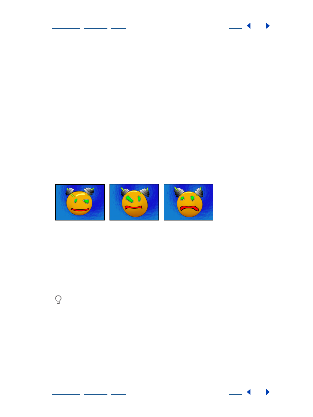
Adobe After Effects Help Distort effects
Using Help | Contents | Index Back 80
• To add a point, Alt-click (Windows) or Option-click (Mac OS) the mask.
• To delete a point, Alt-click or Option-click the point.
• To move a point, drag it to a new location.
• To change the interpolation of a pair of points, Shift-click a point. Smooth interpolation
works best with round masks, while linear interpolation works best with angular masks.
You can combine smooth and linear interpolation in the same composition.
11 Choose an interpolation method, and preview the distortion. If Linear or Smooth
produces undesired results, add more keyframes. If Discrete produces undesired results,
choose another method.
Ripple
The Ripple effect creates the appearance of ripples in a specified layer, moving away from
a center point in concentric circles. The effect is similar to dropping a stone in a pond. You
can also specify that ripples move toward the center point.
Animate ripples at a constant speed using the Wave Speed control. This control does not
require keyframes for animation. Animate ripples at varying speeds by creating keyframes
for the Ripple Phase control.
Animated Ripple effect
Ripple controls
Adjust the following controls for the Ripple effect:
Radius Controls the distance the ripples travel from the center point. The Radius value is a
percentage of the image size. If the center of the ripple is the center of the layer and the
radius is set to 100, the ripples travel to the edge of the image. A value of 0 produces no
ripples. Like ripples in water, ripples in the layer become smaller as they travel farther from
the center.
To create a single-wave ripple, set Radius to 100, Wave Width between 90 and 100, and
Wave Height as desired.
Center or Ripple Specifies the center of the effect.
Type of Conversion Specifies how the ripples are created. Asymmetric produces more
realistic-looking ripples; asymmetric ripples include lateral motion and produce more
distortion. Symmetric produces motion that travels only outward from the center point;
symmetric ripples produce less distortion.
Using Help | Contents | Index Back 80
Page 81

Adobe After Effects Help Distort effects
Using Help | Contents | Index Back 81
Wave Speed Sets the speed at which the ripples travel outward from the center point.
When you specify a wave speed, the ripples are automatically animated at a constant
speed (without keyframes) across the time range. A negative value makes the ripples
move toward the center, and a value of 0 produces no movement. To vary wave speed
over time, set this control to 0, and then create a keyframe for the Ripple Phase property of
the layer.
Wave Width Specifies the distance, in pixels, between wave peaks. Higher values produce
long, undulating ripples, and low values produce many small ripples.
Wave Height Specifies the height of the ripple wave. Taller waves produce greater
distortion.
Ripple Phase Specifies the point along the waveform at which a wave cycle begins. The
default value of 0 degrees starts the wave at the midpoint of its downward slope; 90
degrees starts it at the lowest point in the trough; 180 degrees starts it at the midpoint of
the upward slope, and so on.
Smear
Using the Smear effect, you define an area within an image and then move that area to a
new location, stretching, or
to define the area you want to distort.
To use Smear, first create or import two masks: the source mask and the boundary mask.
You can create masks on the layer in After Effects or use masks created in Adobe Illustrator.
To use a mask created in Illustrator, copy the mask and paste it into a layer in After Effects.
Masks must be closed to work with Smear; if a mask is an open trace, After Effects closes it
when you select it. Both masks must be on the same layer as the footage to which you will
apply the Smear effect, although you can copy masks from another layer.
Original (left) and with variations of Smear applied (center and right)
When you move the source mask within the image, Smear stretches the portion of the
image inside the boundary mask to follow the edges of the source mask. The boundary
mask tries to protect the image outside it from being stretched. Both the original position
of the source mask (set in the Layer window) and the offset position of the source mask are
displayed in the Composition window. The first position of the source mask is indicated by
a light red outline, and the new position is indicated by a dark outline.
smearing, the surrounding part of the image with it. Use masks
Using keyframes, you can animate the position, size, and rotation of the source mask as it
moves to its offset position. You can also animate the original position of the source mask
in the Layer window using keyframes.
Processing can take up to several minutes with certain settings. Computation time
increases as the source mask gets closer to the boundary mask. Processing is interrupted
when you click a control.
Using Help | Contents | Index Back 81
Page 82

Adobe After Effects Help Distort effects
Using Help | Contents | Index Back 82
Smear controls
Adjust the following controls for the Smear effect:
Source Mask Specifies a mask as the source mask. By default, After Effects selects the
second mask you create or import for the layer as the source mask.
Note: You must specify both a boundary mask and a source mask to create a distortion.
Boundary Mask Specifies a mask as the boundary mask. By default, After Effects selects
the first mask you create or import as the boundary mask.
Mask Offset Specifies a destination position for the source mask. The offset is a position
specified by
offset location, click the Offset button, and then click the image in the desired location. To
set the offset position numerically, type a new value for each axis. When you don’t need
the precision provided by Mask Offset, you can simply drag the source mask offset in the
Composition window.
Note: Unwanted undulations may occur if the source mask is close to the boundary mask
during animation.
Mask Rotation Rotates the source mask around its center point, between 0 and 360
degrees.
x and y coordinates, which appear to the right of the Offset button. To set an
Mask Scale Scales the source mask (at its offset position) larger or smaller, in relation to
its original position.
Percent Specifies what percent of the smear is actually performed. For example, when
Percent is set to 50%, Smear performs half of the smear you have specified by moving,
scaling, and rotating the source mask. This value doesn’t affect the location of the original
and offset positions of the source mask; it affects only the percent of the effect that is
performed.
Elasticity Specifies how closely the image follows the shape defined by the curve. Stiff
distorts the least, while Super Fluid distorts the most. In general, use the stiffest setting
possible that doesn’t create polygonal images.
Interpolation Method Specifies a method for the interpolation that Smear performs
between keyframes. Linear requires two or more keyframes and performs a straight-line
interpolation between the keyframes. Linear produces robot-like animations in which the
distortions change at keyframes. Smooth requires three or more keyframes and approxi
mates the distortion using cubic curves, producing distortions with graceful motion. If you
need further accuracy in the animation between keyframes, add more keyframes. For
example, a distortion representing a 90-degree rotation between two keyframes appears
as a folding of the image. To make this distortion more fluid, add a keyframe for every 10
degrees.
-
Using the Smear effect
The following procedure provides a basic overview of how to use this effect.
To use Smear:
1 Open the layer in a Layer window.
2 Create or paste the masks you will use as the boundary mask and the source mask.
3 Position the boundary mask to specify the area of the layer you do not want Smear to
affect.
Using Help | Contents | Index Back 82
Page 83
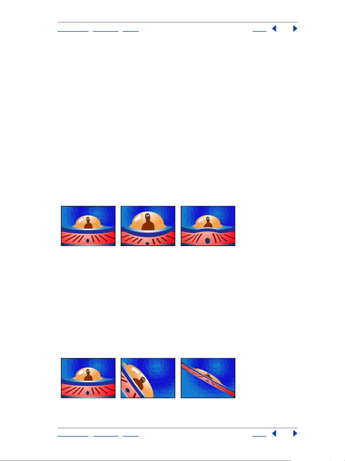
Adobe After Effects Help Distort effects
Using Help | Contents | Index Back 83
4 Scale and position the source mask over the area you want to move.
5 Make the Composition window active, and choose Effects > Distort > Smear.
6 Enter a Percent value to specify the amount of smear applied.
7 In the Composition window, move the source mask to its destination position by
dragging it or by using the Mask Offset value.
8 Use the Mask Rotation control to rotate the source mask, and use the Mask Scale
control to scale it.
9 Drag the Percent slider as needed, and choose a setting for Elasticity.
Spherize
The Spherize effect distorts a layer by wrapping a region of the image onto a spherical
shape of variable size. The layer’s quality setting influences the Spherize effect. Best quality
samples the displaced pixels to subpixel accuracy; Draft quality samples to the nearest
whole pixel.
The Radius option specifies the radius of the sphere in pixels. You can exceed the highest
slider value by clicking the Radius value and typing a higher number in the dialog box.
Center of Sphere specifies the position of the sphere’s center on the layer.
Original (left) and with variations of Spherize applied (center and right)
Transform
The Transform effect applies 2D geometric transformations to the source layer. This effect
supplements the transform properties available for each layer in the Timeline window.
Using the Transform effect, you can skew a layer along any axis. Also, if motion blur is
enabled in the Switches column, you can specify motion blur independently of the
composition’s shutter angle. Anchor Point, Position, Rotation, and Opacity function the
same as the layer transform properties in the Timeline window.
Note: This effect is relative to the input layer. Therefore, to make a layer rotate around the
upper left corner, open the Layer window, choose Transform from the Layer window menu,
and then move the anchor point and the position to the upper left corner.
Original (left) and with variations of Transform applied (center and right)
Using Help | Contents | Index Back 83
Page 84
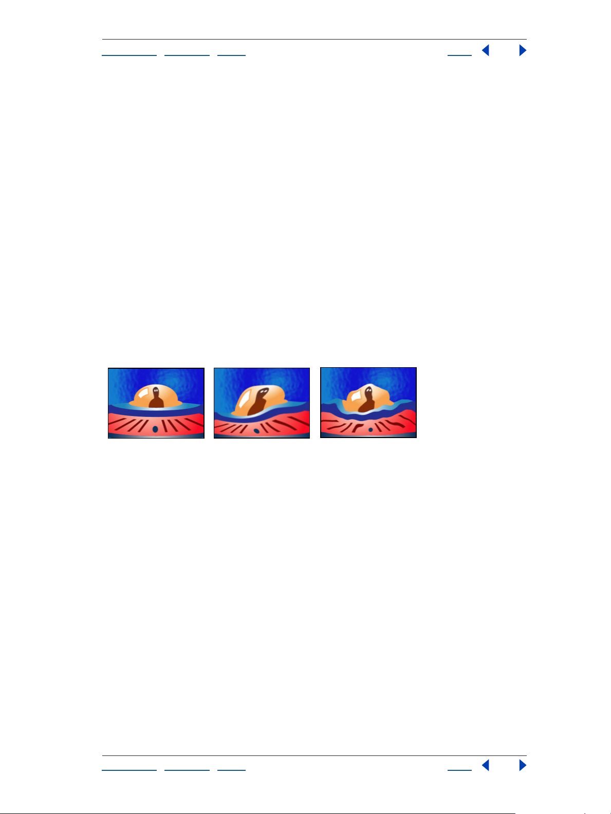
Adobe After Effects Help Distort effects
Using Help | Contents | Index Back 84
Adjust the following controls for the Transform effect:
Scale Height Scales height up or down as a percent of the current layer height.
Scale Width Scales width up or down as a percent of the current layer width.
Skew Specifies skew amount.
Skew Axis Specifies the axis on which the skew is based. Changing the skew axis has no
effect if Skew is 0.
Use Composition’s Shutter Angle Specifies that the Transform effect uses the shutter
angle of the composition when performing motion blur. If this control is not selected, the
Transform effect uses the option for the Shutter Angle control.
Shutter Angle Determines the amount of motion blur to apply to the layer. (Motion Blur
must be enabled for the layer.)
Uniform Scale Scales both the width and the height of an image.
Turbulent Displace
The Turbulent Displace effect uses fractal noise to create turbulent distortions in an image.
This effect is useful for adding distorted movement to a layer. For example, use it to create
flowing water, funhouse mirrors, and waving flags.
Original (left) and with variations of Turbulent Displace applied (center and right)
Turbulent Displace controls
Adjust the following controls for Turbulent Displace:
Displacement Specifies the type of turbulence used. Turbulent, Bulge, and Twist warp
the image in slightly different directions. Turbulent Smoother, Bulge Smoother, and Twist
Smoother each perform the same operation as Turbulent, Bulge, and Twist, except that
they create smoother warps and may take longer to render. Vertical Displacement warps
the image vertically only. Horizontal Displacement warps the image horizontally only.
Cross Displacement warps the image both vertically and horizontally.
Amount Specifies the amount of displacement in the layer. Higher values result in more
distortion in the
Size Specifies the size or radius of the displaced or distorted areas in the layer. Higher
values result in larger areas of distortion.
Offset Specifies the portion of the fractal shape that is present in the Composition
window, altering the shape of the distortion on your layer. Because the fractal shapes used
are infinite in all directions, what appears in the Composition window is only a small
portion of the entire fractal. The Composition window behaves like a fixed viewing area,
and the Offset control repositions the fractal within that view, which then brings a
different portion of the fractal into view. This alters the shape of the distortion.
layer.
Using Help | Contents | Index Back 84
Page 85

Adobe After Effects Help Distort effects
Using Help | Contents | Index Back 85
Complexity Specifies the level of detail in the turbulence. Increasing the Complexity
value increases the detailed definition in the displacement pattern. Lower values result in
smoother distortions.
Evolution Specifies the changes of the turbulence over time.Evolution values are
progressive, not looping. The image continues to change with each added revolution. The
appearance of the image when this option is set to 0 is different from that at 1 revolution,
which, in turn, is different from that at 2 revolutions, and so on. The evolution state
progresses infinitely at each new value. To force the Evolution setting to return to its
original state (necessary to create a seamless loop) set the Evolution Options control to
Cycle Evolution.
Set keyframes for Evolution to determine how much the turbulence evolves over the
period of time allowed between keyframes. The more revolutions that are made between
keyframes the more rapidly the turbulence changes. Higher values may result in flashing
rather than smooth changes.
Evolution Options Specifies how you render the effect’s evolution values. This control is
useful to create one short seamless evolution cycle (where the last frame matches up to
the first) to be prerendered and looped as a new source layer in a composition, rather than
setting Evolution to animate over a greater number of frames. Options include the
following:
• Cycle Evolution creates a cycle of evolution that loops over a set amount of time. Cycle
Evolution returns the evolution state to its starting point to create a smooth,
progressive, looping animation. Copied and pasted evolution keyframes start and end
with the same value, and the resulting animation repeats, rather than producing a
smoothly transitioning cycle.
• Cycle specifies the number of revolutions of the Evolution setting that the fractal noise
cycles through before it repeats. The amount of time allowed between evolution
keyframes determines the timing or speed of these evolution cycles. Higher values
create longer render times. Cycle affects only the state of the fractal, not geometrics or
other controls. For example, two identical states of the fractal don’t appear the same if
viewed with different Size or Offset settings.
• Random Seed specifies a unique random value from which to generate the turbulence.
Animating the random seed value results in flashing from one set of fractal shapes to
another (within that fractal type). For smooth transition of the turbulence, use the
Evolution control.
Pinning Specifies how the effect pins the edges of an image so that it remains in its initial
position. The None option pins no layer edges. Pin All, Pin Horizontal, and Pin Vertical
minimize the effect of the turbulence on the corresponding layer edges. All Locked
Options locks the layer edge so that turbulence doesn’t affect it.
Resize Layer Enables the distorted image to expand past the layer’s bounding box.
Antialiasing for Best Quality Specifies the level of anti-aliasing of the displacement
pattern. This control works best if the layer is set to Best quality in the Timeline window.
Creating a seamless loop
The following procedure provides a basic overview of how to create a seamless loop of
turbulence.
Using Help | Contents | Index Back 85
Page 86
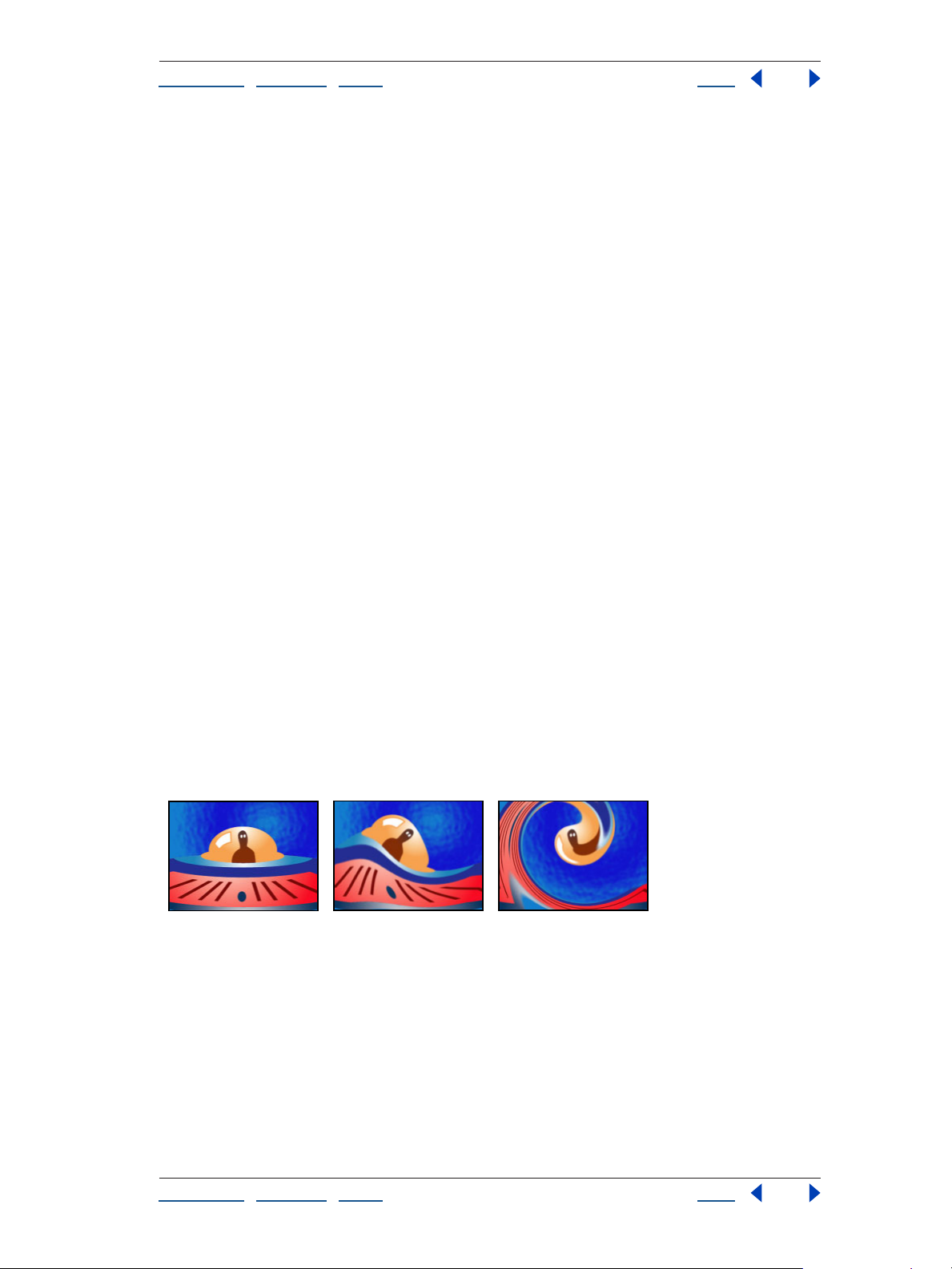
Adobe After Effects Help Distort effects
Using Help | Contents | Index Back 86
To create a seamless loop using Turbulent Displace:
1 Set two keyframes for the Evolution control, using full revolutions only.
2 Adjust the time allowed between keyframes, and the number of Evolution revolutions
until you are satisfied with the appearance of the displacement.
3 Under Evolutions Options, select Cycle Evolution.
4 Under Evolutions Options, drag the Cycle slider to set a value for Cycle that either
matches or is evenly divisible by the number of revolutions you set for Evolution.
5 Move the current-time indicator to the point on the Timeline window where the Cycle
completes. For example, if the Cycle value is 2, find the frame on the Timeline window
where the Evolution value is 2 revolutions.
6 Move the current-time indicator back one frame. (Because the cycle begins again at the
last frame, moving the current-time indicator back prevents a duplicate frame in the
seamless loop.)
7 Trim the layer’s out point.
8 Prerender this layer, and import it into your project.
9 Set this prerendered footage item to loop. For information on looping footage, see the
After Effects 6.0 User Guide.
Note: If you set keyframes for any of the other controls, you must return them to their
initial settings at the point on the Timeline window where the cycle begins to repeat.
Otherwise, these properties don’t loop.
Twirl
The Twirl effect twirls the pixels of an image around a specified point at a specified
amount. Pixels nearer the center point are twirled faster than pixels in outer regions,
resulting in a whirlpool appearance. Because distortion in this effect is significant, After
Effects uses special anti-aliasing techniques to produce the highest-quality image. As a
result, the Twirl effect can be particularly slow to render.
Twirling a layer
Adjust the following controls for the Twirl effect:
Angle Specifies how far and in which direction to twirl the image around the twirl center.
Positive angles twirl the image clockwise; negative angles twirl it counterclockwise. To
animate the twirl as a whirlpool, set keyframes for the angle.
Twirl Radius Specifies how far the twirl extends from the twirl center. This value is based
on a percentage of the maximum horizontal or vertical distance of the layer, whichever is
greater. A value of 50, for example, produces a twirl that extends to the edge of the
layer.
Using Help | Contents | Index Back 86
Page 87

Adobe After Effects Help Distort effects
Using Help | Contents | Index Back 87
Warp
Use Warp to distort or deform After Effects layers. The 15 warp styles work much like the
Warp effects in Adobe Illustrator and Warp Text in Adobe Photoshop.
Warping a layer
To apply Warp:
1 Select an object or group of objects.
2 Choose Effect > Distort > Warp.
3 In the Effect Controls window choose a warp style.
4 Choose Horizontal or Vertical from the Warp Axis menu to specify which axis the warp
affects.
5 Drag the Bend slider to specify the amount of bending.
6 Drag the appropriate sliders to specify the amount of horizontal and vertical distortion.
Wave Warp
The Wave Warp effect produces the appearance of a wave traveling across an image. You
can produce a variety of different wave shapes, including square, circular, and sine waves.
The Wave Warp effect is automatically animated at a constant speed across the time range
(without keyframes). To vary speeds, you need to set keyframes.
Original (left) and with variations of Wave Warp applied (center and right)
First example: Sine wave, small width and height
second example: Semicircle wave, medium width and height
Wave Warp controls
Adjust the following controls for the Wave Warp effect:
Wave Type Specifies the shape of the wave.
Wave Height Specifies the height of the wave. Taller waves generally produce greater
distortion.
Using Help | Contents | Index Back 87
Page 88

Adobe After Effects Help Distort effects
Using Help | Contents | Index Back 88
Wave Width Specifies the distance, in pixels, between wave peaks. Smaller values
produce more
waves.
Direction Specifies the direction the wave travels across the image. For example, a value
of 90 degrees makes waves travel from left to right. A value of 180 degrees makes waves
travel from top to bottom, and a value of 225 degrees makes the waves travel diagonally
from upper right to lower left.
Wave Speed Sets the speed (cycles per second) at which the waves travel. When you
specify a wave speed, the ripples are automatically animated at a constant speed across
the time range (without keyframes). Click the wave speed value to specify negative values
or values greater than 5. A negative value reverses the wave direction, and a value of 0
produces no movement. To vary wave speed over time, set this control to 0, and then set
keyframes for the Phase property of the layer.
Pinning Specifies areas of the image to be excluded from the wave. For example, if All
Edges is selected, the wave does not travel across the edges of the image.
Phase Specifies the point along the waveform at which a wave cycle begins. The default
value of 0 degrees starts the wave at the midpoint of its downward slope; 90 degrees
starts it at the lowest point in the trough; 180 degrees starts it at the midpoint of the
upward slope, and so on.
Antialiasing Sets the amount of anti-aliasing, or edge smoothing, to perform on the
image. Anti-aliasing is applied only when the layer is set to Best quality. In many cases,
lower settings produce satisfactory results; a high setting can significantly increase
rendering time.
Using Help | Contents | Index Back 88
Page 89
Adobe After Effects Help Expression Controls effects
Using Help | Contents | Index Back 89
Expression Controls effects
About Expression Controls effects
You can use Expression Controls effects to manipulate property values in your expressions.
By referring to these controls in an expression, you can more easily adjust parameters such
as layer, color, and angle. For more information about Expression Controls effects, see the
“Using Expressions” chapter in the online Help or printed guide.
Using Help | Contents | Index Back 89
Page 90

Adobe After Effects Help Image Control effects
Using Help | Contents | Index Back 90
Image Control effects
Change Color
The Change Color effect adjusts the hue, saturation, and lightness of a range of colors.
Choose the range by specifying a base color and similarity values. The similarity can be an
RGB similarity, a hue similarity, or a chroma similarity.
Colors in the original image (left) are replaced with green (center) and yellow (right).
Controls for the Change Color effect
Adjust the following controls for the Change Color effect:
View Specifies what to view in the composition. Corrected Layer shows the results of the
Change Color effect. Color Correction Mask shows the areas of the layer that will be
changed. White areas in the color correction mask are transformed the most, and dark
areas are transformed the least.
Hue Transform Specifies the amount, in degrees, to adjust the hue of the selected colors.
Lightness Transform Specifies the amount to increase or decrease the lightness of the
selected colors. Positive values brighten the selected regions; negative values darken
them.
Saturation Transform Specifies the amount to increase or decrease the saturation of the
selected colors. Positive values saturate the selected regions (moving toward pure color);
negative values desaturate the selected regions (moving toward gray).
Color to Change Specifies the color to be changed. Matching Tolerance and Matching
Softness both use this color as a target for building the color correction mask.
Matching Tolerance Specifies the degree of color matching before the color is affected
by the color correction. With low tolerances, only colors very similar to the change color
are added to the color correction mask. Larger tolerances add more of the image to the
color correction mask.
Matching Softness Specifies the softness of the color correction. This control does not
always soften the color correction mask geometrically, but it affects the severity of the
color correction for regions similar to the base color.
Using Help | Contents | Index Back 90
Page 91
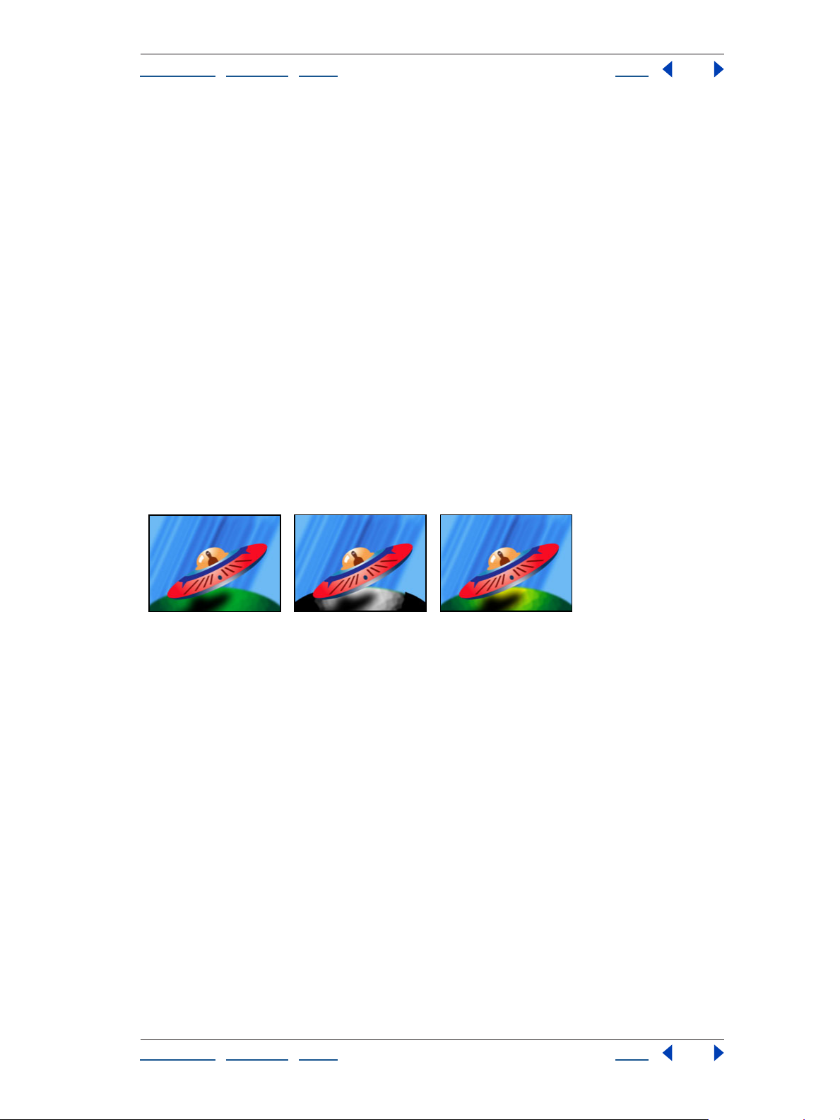
Adobe After Effects Help Image Control effects
Using Help | Contents | Index Back 91
Match Colors Specifies the criterion for determining the similarity of two colors. RGB uses
the red, green, and blue components. Hue matches colors based on hue. For example,
bright red, light pink, and burgundy have similar hue values (a hue of red, but differing
values of saturation and lightness). Chroma uses the two chromatic components to
determine similarity, ignoring brightness. Chroma matching is therefore sensitive to
saturation and hue differences, but not to lightness differences.
Invert Color Correction Mask Inverts the mask that determines which colors to affect. If
selected, all colors will be color-corrected, except those selected by using Color to Change
and matching controls.
Change to Color (formerly Change Color HLS)
The Change to Color effect changes a color you select in an image to another color using
hue, lightness, and saturation (HLS) values. Perform color changes either by transforming
or interpolating into the new color. This filter is useful for quickly changing one selected
color to another, while leaving other colors in the image unaffected.
Change to Color offers flexibility and options unavailable in the Change Color effect. These
options include tolerance sliders for hue, lightness, and saturation for exact color
matching, and the ability to select the exact RGB values of the target color that you wish to
change to.
Original (left), with saturation removed in the planet (center), and with light green changed to yellow
in the planet (right)
Controls for the Change to Color effect
Adjust the following controls for the Change to Color effect:
From Specifies the color that you wish to change. This selection determines which pixels
will be affected by the color
To Specifies the color that you wish to change to. This control determines the target color
for selected pixels.
Change Specifies the HLS channels that are affected. Hue affects hue only, leaving the
original lightness and saturation untouched. Hue and Lightness affects hue and lightness
only, leaving the original saturation untouched. Hue and Saturation affects hue and
saturation only, leaving the original lightness untouched. Hue, Lightness, and Saturation
affects all the channels.
Change by Specifies the color change operation the effect performs. Setting to Color
performs a direct change of affected pixels to the target color. Transforming to Color trans
forms affected pixel values towards the target color, using HLS interpolation. The amount
of transformation depends on how close the selected To pixel color lies to the From color
and also on the Tolerance value.
change.
-
Using Help | Contents | Index Back 91
Page 92

Adobe After Effects Help Image Control effects
Using Help | Contents | Index Back 92
Tolerance Specifies the range of pixels that Change to Color affects. Expand this control
to reveal separate sliders for Hue, Lightness, and Saturation values. Higher Tolerance
values expand the range of similar values. Lower Tolerance values reduce the range of
similar values.
Note: Use the View Correction Matte option to better identify which pixels are affected.
Softness Specifies the edge smoothness of the selected change areas. Higher values
create smoother and more seamless transitions between areas affected by the color
change and those left unaffected.
View Correction Matte Specifies whether or not you are viewing a grayscale mask of the
color values. White areas indicate pixels that are affected by the color change. Black areas
are left unchanged. Gray areas are only slightly affected by the color change.
To animate a color change, first select the initial color you wish to change; then set
subsequent keyframes only for the To color.
Color Balance (HLS)
The Color Balance (HLS) effect alters an image’s levels of hue, lightness, and saturation. It is
intended only to provide compatibility with projects created in earlier versions of After
Effects that use the Color Balance (HLS) effect. For new projects, use the Hue/Saturation
effect, which operates the same as the Hue/Saturation command in Adobe Photoshop.
You can convert a movie to grayscale by setting the Saturation to –100.
Original image (left), with increased hue and saturation (center), and increased saturation only
(right)
Color Link
The Color Link effect colorizes one layer with the average pixel values of another selected
layer. This effect is useful for quickly finding a color that matches the color of a background
layer.
Original (left), with background color linked to the planet (center), and with background color linked
to the saucer (right)
Controls for the Color Link effect
Adjust the following controls for Color Link:
Using Help | Contents | Index Back 92
Page 93

Adobe After Effects Help Image Control effects
Using Help | Contents | Index Back 93
Source Layer Select the layer from which you wish to sample colors. Color Link chooses
your original layer if None is selected.
Note: If you choose None, Color Link samples from the original layer, taking into account
any masking or other effects that you have applied. If you choose the original layer’s name
from the menu, Color Link samples from the source layer before masking or effects are
applied.
Sample Specifies which values the effect samples from the source layer and subsequently applies to the effect layer.
• Average averages all RGB values from all opaque pixels in the source layer. This is useful
if you are selecting a specific region of pixels defined with a mask. Median samples the
pixel value that falls in the middle of all RGB values.
• Brightest samples the brightest RGB value, using lightness, and Darkest samples the
darkest RGB value, also using lightness.
• Max RGB samples the highest value of the individual RGB channels. Min RGB samples
the lowest value of the individual RGB channels.
• Average Alpha samples only the average alpha channel value. Median Alpha samples
the value that falls in the middle of all alpha channel values. Max Alpha samples the
highest value of the alpha channel. Min Alpha samples the lowest value of the alpha
channel.
Clip Specifies the percentage of the highest or lowest sampled target values that the
effect disregards. This is useful for reducing the influence of noisy pixels in an image.
Stencil Original Alpha If this box is checked, the effect places a stencil of the effect
layer’s original alpha channel over the new value. If this box is unchecked, the effect disre
gards the original alpha channel and fills the entire effect layer with the average value of
the source layer.
Opacity Specifies the transparency of the effect layer.
Blending Mode Specifies the blending mode that the effect uses to combine the new
colorized layer with the original layer. These blending modes behave exactly like those in
the Timeline. (Blending modes are not available when averaging alpha channel values in
the layer.)
-
Using Help | Contents | Index Back 93
Page 94

Adobe After Effects Help Image Control effects
Using Help | Contents | Index Back 94
Colorama
The Colorama effect assigns a custom palette to an element in a layer and then cycles the
palette. First you colorize an image with a specified palette, and then you cycle the colors
in that palette—that is, change them smoothly around the Output Cycle palette or color
wheel. Color cycling is a quick way to animate pulsing colors that follow a gradient path,
colors that zoom out of a radial gradient, and many other effects.
Original (left), with background cycling through colors (center), and with an inverted alpha mask
(right)
Colorama works by first converting a specified property to grayscale and then remapping
the grayscale values to the specified color palette. The current color palette appears on the
Output Cycle color wheel.
The grayscale is then “wrapped around” the color wheel. Black pixels are mapped to the
color at the top of the cycle, while increasingly lighter grays are mapped to successive
colors going clockwise around the cycle, until this process wraps around to the start again
at full white. For example, with the default “Hue cycle” palette, pixels corresponding to
black become red, while pixels that have been converted to 50% gray become cyan. You
can animate the cycle so that in one revolution, each pixel of the layer travels through the
complete color cycle.
Customizing a palette with the Colorama effect
You can customize any palette by altering the colors and locations of the triangles around
the Output Cycle control of the Colorama effect, using any of the following procedures.
To add a triangle:
Click in or near the color wheel, and select a color from the color picker.
To duplicate a triangle:
Press Ctrl (Windows) or Command (Mac OS), and drag the triangle to the new position.
To change the color of a triangle:
Do any of the following:
• Double-click a triangle, and select a color from the color picker.
• To make a triangle ignore its original color and instead “sample” the color of its new
location on the color wheel, click the triangle and then press Ctrl (Windows) or
Command (Mac OS). To avoid deleting the original color, you may want to duplicate the
triangle first.
• To change the opacity, select a triangle on the color wheel and then drag the attached
triangle above the opacity slider. Make sure that Modify Alpha is selected if you want
the opacity information to affect your output.
Using Help | Contents | Index Back 94
Page 95

Adobe After Effects Help Image Control effects
Using Help | Contents | Index Back 95
To change where the color of a specific triangle appears on the color wheel:
Do any of the following:
• Drag a triangle.
• Press Shift as you drag to snap the triangles to the 45-degree increments around the
wheel.
Note: To snap a triangle to the start or end point of the color wheel, press Shift and move
the pointer slightly to the right (start point) or left (end point) of the top of the wheel.
To delete a triangle:
Drag it away from the color wheel.
Adjusting lightness or hue levels using the Colorama effect
The following procedures provide two methods of adjusting the levels of an image:
To adjust hue levels:
1 Expand the Input Phase control, and choose Hue from the Get Phase From menu.
2 Expand the Output Cycle control, and choose Hue Cycle from the Use Preset Palette
menu.
3 Expand the Modify control, and choose Hue from the Modify menu.
4 (optional) Animate the Phase Shift control to cycle the hues in the image.
5 (optional) Choose an animated gradient layer from the Add Phase menu to modulate
the hue.
To adjust lightness levels:
1 Expand the Input Phase control, and choose Lightness from the Get Phase From menu.
2 Expand the Output Cycle control, and choose Ramp Grey from the Use Preset Palette
menu.
3 Choose Lightness from the Modify menu.
4 Add a triangle to the Output Cycle at 3 o’clock and another at 9 o’clock, and then drag
them toward 6 o’clock. This setting expands shadows and highlights while compressing
the midtones of an image.
Input Phase controls for the Colorama effect
Specify which layer and property are colorized by the Colorama effect:
Get Phase From Specifies the property to which the Output Cycle is applied. Select Zero
if you want to use a property from another layer.
Add Phase Specifies the layer containing the property that you want to apply to the
Output Cycle. To use this layer instead of the first layer, select Zero for Get Phase From;
otherwise, this layer becomes a secondary property to the first property. Add Phase From
specifies the property to use from the Add Phase layer.
Add Mode Specifies how Colorama combines properties from two layers.
• Wrap adds the values of the two properties for each pixel. A pixel cannot be whiter than
100%, so sum values above 100% are wrapped around the cycle again. For example, a
sum of 150% wraps back to 50%.
Using Help | Contents | Index Back 95
Page 96
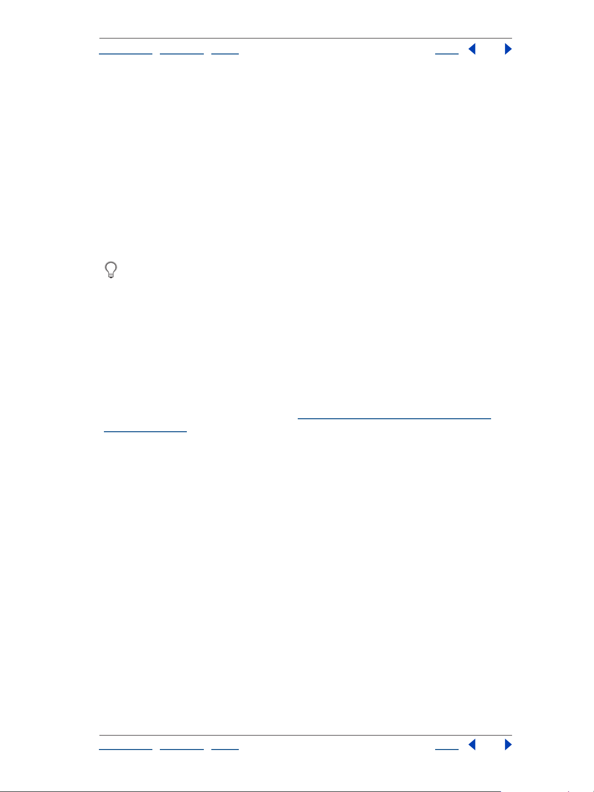
Adobe After Effects Help Image Control effects
Using Help | Contents | Index Back 96
• Clamp adds the values up to 100%. The sum of any two pixels that is greater than 100%
is rounded back down to 100%.
• Average adds two pixels together and then divides by two. Average values never wrap
or clamp, making this option the safest choice for predictable output.
• Screen screens the second layer over the original layer; the brighter areas in the second
layer brighten the first layer, and the darker areas in the second layer are discarded.
Screen mode is especially useful for compositing fire, lens flares, and other lighting
effects.
Phase Shift Shifts the colors around the color wheel. If you animate Phase Shift, the
modified pixels cycling among the colors defined in the Output Cycle palette. A positive
value moves the pixels in a clockwise direction; a negative value moves them counter
-
clockwise.
Animate Phase Shift to cycle the colors around the color wheel. Phase Shift is the
parameter that is most commonly animated.
Output Cycle controls for the Colorama effect
Specify the colors used to colorize the image:
Use Preset Palette Specifies the palette for the color cycle. The top palettes are designed
for quick color-management tasks. The bottom choices offer a variety of built-in color
effects.
Output Cycle Specifies the color palette you are currently working with. The triangles
specify the location on the color wheel where a specific color occurs. The color between
triangles is smoothly interpolated, unless Interpolate Palette is off. You can add up to a
total of 64 triangles per Output Cycle. (See
“Customizing a palette with the Colorama
effect” on page 94.)
Note: When you keyframe the Output Cycle, a triangle’s position and color are interpolated between keyframes. For best results, make sure that all keyframes have the same
number of Output Cycle triangles.
Cycle Repetitions Controls how the Output Cycle pixels are applied to the Input Phase.
The default value of 1 maps the Output Cycle once from Input Phase black to Input Phase
white. A value of 2 maps the Output Cycle twice, once from 1% to 50%, and again from
51% to 100%. Use this option to create a simple palette and repeat it many times
throughout a gradient. For example, you can create running lights, in which one cycle
repeated 20 times generates 20 lights.
Interpolate Specifies whether or not colors between triangles are interpolated
smoothly. When it is not selected, the output is posterized. For example, with Interpolate
Palette not selected, the default Hue Cycle palette becomes a useful tool for preparing
custom shatter maps for use with the Shatter effect.
Using Help | Contents | Index Back 96
Page 97

Adobe After Effects Help Image Control effects
Using Help | Contents | Index Back 97
Modify controls for the Colorama effect
Modify controls specify which properties are modified by the Colorama effect. Once the
Input Phase pixels are mapped to a color on the Output Cycle, the results are applied to
the property selected here. You can get a great deal of selective control by choosing the
same property for the Input Phase and the Modify property, along with an appropriate
Output Cycle.
Note: Because the input layer is represented as a grayscale file, the Ramp Grey preset
palette works well and is most predictable with any Modify setting other than All.
Modify Specifies the specific property to be modified.
Modify Alpha Specifies whether the opacity information in your Output Cycle is applied
to the output. Selecting Modify Alpha changes the alpha information along with the other
channels selected from the Modify menu. Modify Alpha works in conjunction with the
Change Empty Pixels option in determining the final change in opacity.
Note: If you apply Colorama to a layer with an alpha channel, and the Output Cycle does
not contain alpha information, the anti-aliased edges of the layer may appear pixelated.
To smooth the edges, deselect Modify Alpha. If Modify Alpha is selected and the Output
Cycle contains alpha information, the output is affected even if you’ve selected None from
the Modify menu. This is how you can adjust the levels of just the alpha channel without
also changing the RGB information.
Change Empty Pixel Specifies whether you want Colorama’s effects to extend into the
transparent areas of your layer as well. ( This works only when Modify Alpha is selected.)
Pixel Selection, Masking, and other controls for the Colorama effect
Adjust the controls to choose which colors in your image you want to affect.
Pixel Selection For the Matching controls for Pixel Selection to work, Matching Mode
must be set to anything other than Off.
• Matching Color specifies the specific pixel color to which you want to apply Colorama.
To select a specific color in the image using the eyedropper tool, turn off the Colorama
effect temporarily.
• Matching Tolerance specifies how close a color has to be to the Matching Color option
before it is affected by Colorama. When Matching Tolerance is 0, only the exact color
selected for Matching Color is affected by Colorama. When Matching Tolerance is 1,
Colorama is tolerant of all colors; this value in effect turns the Matching Mode off.
• Matching Softness specifies the softness between the selected and nonselected areas.
This doesn’t blur the image, but controls how smoothly the Colorama effect blends into
the rest of the image. For example, if you have an image of a man wearing a red shirt
and blue jeans, and you want to change the color of the shirt from red to blue, subtly
adjust Matching Softness to spread the selection from the red in the shirt into the
shadows of the shirt’s folds. If you adjust it too high, the selection spreads to the
healthy pink of the man’s skin; if you adjust it even higher, the selection spreads to his
blue jeans.
• Matching Mode specifies whether a pixel is close to the Matching Color. Use Matching
Mode if Matching Tolerance doesn’t increase the selection in the desired areas. In
general, use RGB for high-contrast graphics and Chroma for photographic images.
Using Help | Contents | Index Back 97
Page 98
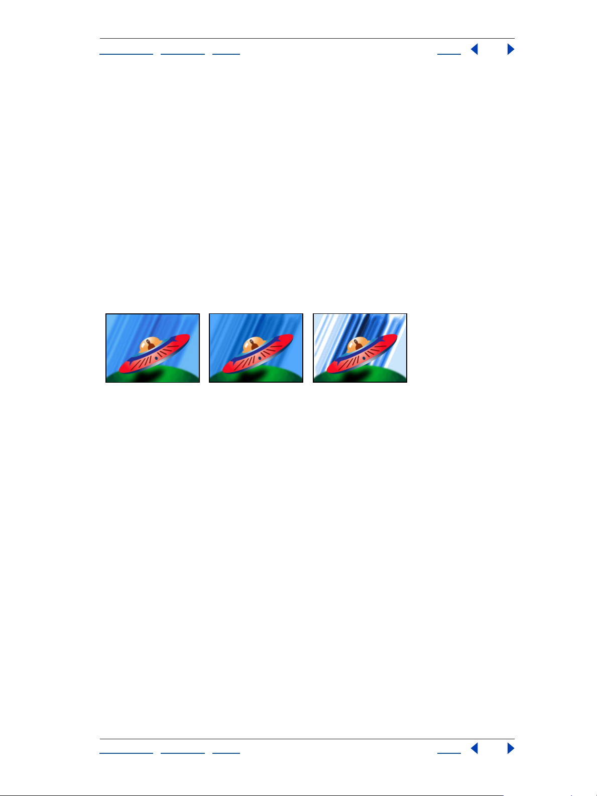
Adobe After Effects Help Image Control effects
Using Help | Contents | Index Back 98
Masking Specifies the pixels you want to change using the luminance or alpha channel
of another layer. Mask Layer specifies the layer you want to use for your mask. Masking
Mode specifies the Mask Layer property to use.
Composite Over Specifies whether you want to see only the selected pixels or the
selected pixels on top of the original layer (the default).
Blend with Original Specifies the relative percentages of the original layer and the
affected layer that you see. Use this control to fade out the Colorama effect.
Equalize
The Equalize effect alters an image’s pixel values to produce a more consistent brightness
or color component distribution. The effect works similarly to the Equalize command in
Adobe Photoshop. Equalization can be performed using either RGB values or the
brightness component. Pixels with 0 alpha (completely transparent) values are not
considered, so masked layers are equalized based on the mask area. Layer quality settings
do not affect Equalize.
Original (left), and with Equalize applied to the background using brightness in varying amounts
(center and right)
Equalize Specifies which equalization method to use. RGB equalizes the image based on
red, green, and blue components. Brightness equalizes the image based on the brightness
of each pixel. Photoshop Style equalizes by redistributing the brightness values of the
pixels in an image so that they more evenly represent the entire range of brightness levels.
Amount to Equalize Specifies how much to redistribute the brightness values. At 100%,
the pixel values are spread as evenly as possible, while lower percentages redistribute
fewer pixel values.
Gamma/Pedestal/Gain
The Gamma/Pedestal/Gain effect adjusts the response curve independently for each
channel. For pedestal and gain, a value of 0.0 is completely off, and a value of 1.0 is
completely on.
Using Help | Contents | Index Back 98
Page 99
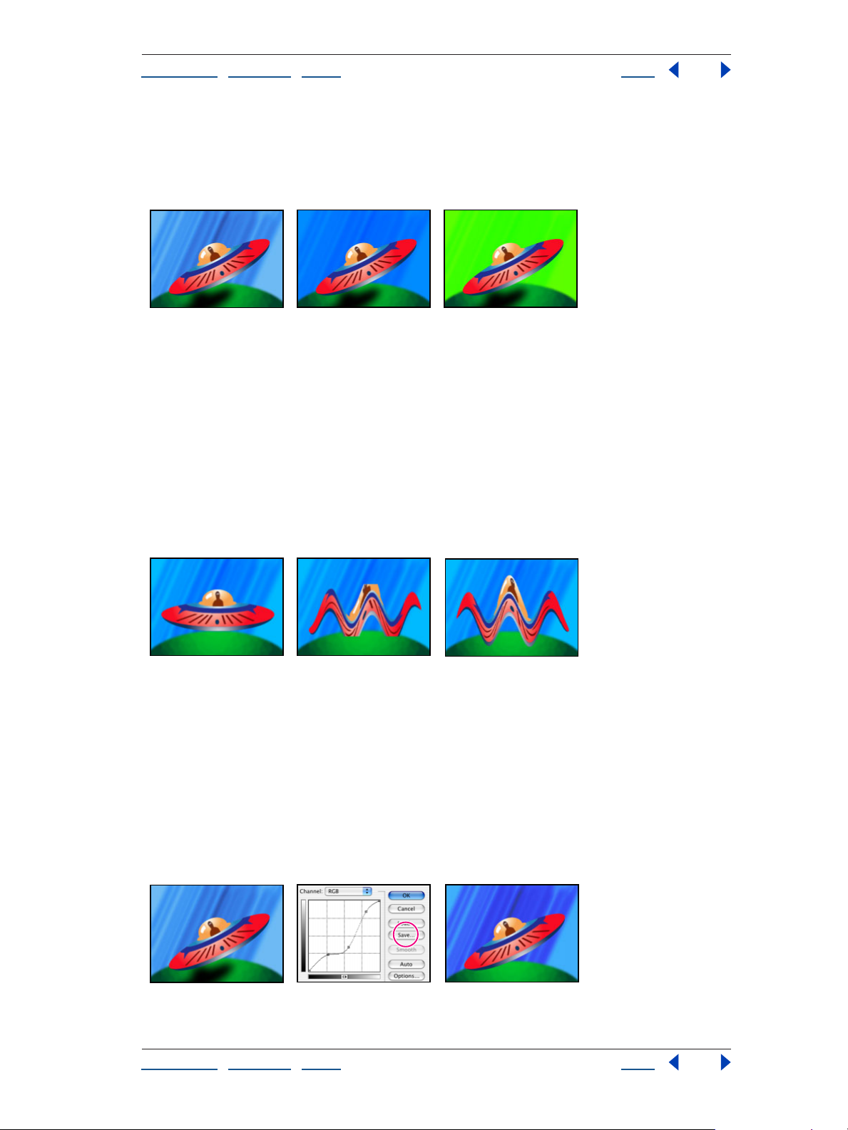
Adobe After Effects Help Image Control effects
Using Help | Contents | Index Back 99
The Black Stretch control remaps the low pixel values of all channels. Large Black Stretch
values brighten dark areas. The effect is the same in all quality settings. Gamma specifies
an exponent describing the shape of the intermediate curve. The Pedestal and Gain
controls specify the lowest and highest attainable output value for a channel.
Original (left) and with varying amounts of Gamma/Pedestal/Gain applied (center and right)
Grow Bounds
The Grow Bounds effect increases the layer size for the effect that directly follows this
effect. It is most useful with layers with Collapse Transformations/Continuously Rasterize
enabled, because they render using a buffer that is the size of the composition. For
example, if you apply Drop Shadow to a Text layer that is partially off the composition, the
shadow will be clipped because only the portion of the text that is in the composition will
cast a shadow. Applying the Grow Bounds effect before the Drop Shadow effect prevents
the shadow from being cut off. The number of pixels you specify increases the height and
width of the layer’s buffer.
The Wave Warp effect is constrained by the dimensions of the layer (center); grow bounds fixes this
problem (right).
PS Arbitrary Map
The PS Arbitrary Map effect applies a Photoshop arbitrary map file to a layer. An arbitrary
map adjusts the brightness levels of an image, remapping a specified brightness range to
darker or brighter tones. In the Curves window in Photoshop, you can create an arbitrary
map file for the entire image or for individual channels. The PS Arbitrary Map effect is
intended only to provide compatibility with projects created in earlier versions of After
Effects that use the Arbitrary Map effect. For new work, use the Curves effect.
An arbitrary map is applied to the background layer (right).
Using Help | Contents | Index Back 99
Page 100
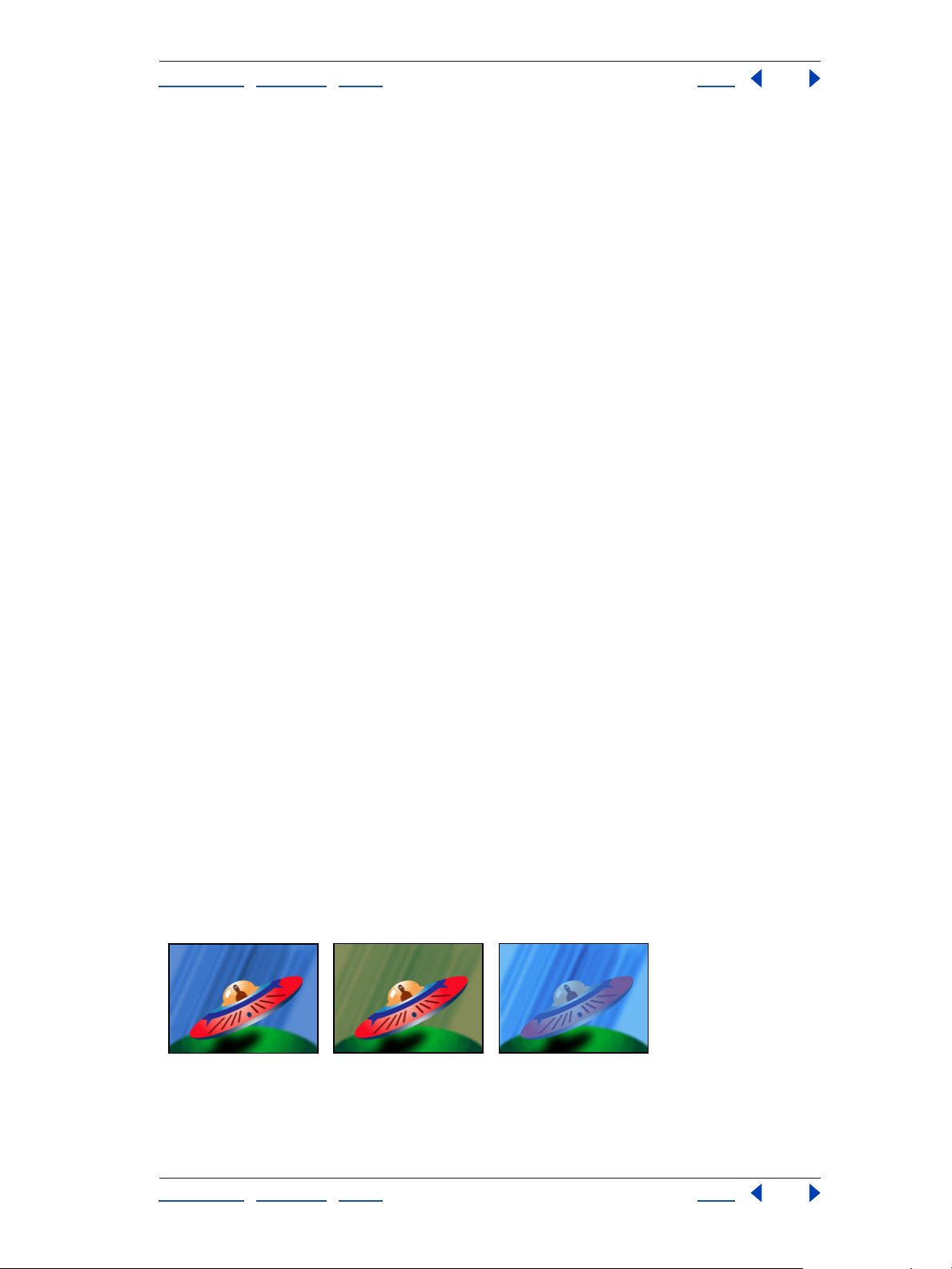
Adobe After Effects Help Image Control effects
Using Help | Contents | Index Back 100
When loaded into After Effects, the specified arbitrary map is applied to the layer or to one
or more channels of the layer, depending on how it was created. If you do not select an
arbitrary map, After Effects applies the default map (linear distribution of brightness) to
the layer. For more information on arbitrary maps, see the Adobe Photoshop 7.0 online
Help topic “Using the Curves dialog box.”
PS Arbitrary Map controls
Adjust the following controls for the PS Arbitrary Map effect:
Phase Cycles through the arbitrary map. Increasing the phase shifts the arbitrary map to
the right (as viewed in the Curves dialog box); decreasing the phase shifts the map to the
left.
Apply Phase Map to Alpha Applies the specified map and phase to the layer’s alpha
channel. If the specified map does not include an alpha channel, After Effects uses the
default map (linear distribution of brightness) for the alpha channel.
Using the PS Arbitrary Map effect
The following procedures provide a basic overview of how to use this effect.
To apply a Photoshop arbitrary map:
In the Effect Controls window, click Options and then select an arbitrary map file.
Although you can’t import .avc files or Photoshop spline files into the After Effects PS
Arbitrary Map effect, you can convert these files in Photoshop to create files that are
compatible with the After Effects Curves effect.
To convert .avc and Photoshop spline files:
1 In the Curves dialog box in Photoshop, load the .acv file (Windows) or the Photoshop
spline file (Mac OS).
2 Click the pencil tool and then save the file as an .amp file (Windows) or a Photoshop
lookup file.
Tint
The Tint effect alters an image’s color information. For each pixel, the luminance value
specifies a blend between two colors. Map Black To and Map White To specify the colors to
which dark and bright pixels are mapped. Intermediate pixels are assigned intermediate
values. Amount to Tint specifies the intensity of the effect. The layer’s quality setting does
not affect Tint. For more complex tinting, use the Colorama effect.
Original (left), with white mapped to green for the background (center), and with black mapped to
dark blue and white mapped to light blue for the foreground (right)
Using Help | Contents | Index Back 100
 Loading...