


Aspire X3812
Table of contents
 Loading...
Acer
Aspire X3812/X5812
Service Guide
PRINTED IN TAIWAN
Service guide files and updates are available
on the ACER/CSD web; for more information,
please refer to http://csd.acer.com.tw

ii
Revision History
Please refer to the table below for the updates made on this service guide.
Date Chapter Updates

iii
Copyright
Copyright © 2009 by Acer Incorporated. All rights reserved. No part of this publication may be reproduced,
transmitted, transcribed, stored in a retrieval system, or translated into any language or computer language, in
any form or by any means, electronic, mechanical, magnetic, optical, chemical, manual or otherwise, without
the prior written permission of Acer Incorporated.

iv
Disclaimer
The information in this guide is subject to change without notice.
Acer Incorporated makes no representations or warranties, either expressed or implied, with respect to the
contents hereof and specifically disclaims any warranties of merchantability or fitness for any particular
purpose. Any Acer Incorporated software described in this manual is sold or licensed "as is". Should the
programs prove defective following their purchase, the buyer (and not Acer Incorporated, its distributor, or its
dealer) assumes the entire cost of all necessary servicing, repair, and any incidental or consequential
damages resulting from any defect in the software.
Acer is a registered trademark of Acer Corporation.
Intel is a registered trademark of Intel Corporation.
Pentium Dual-Core, Celeron Dual-Core, Core 2 Duo, Core 2 Quad, Celeron, and combinations thereof, are
trademarks of Intel Corporation.
Other brand and product names are trademarks and/or registered trademarks of their respective holders.

v
Conventions
The following conventions are used in this manual:
SCREEN
MESSAGES
Denotes actual messages that appear on screen.
NOTE Gives additional information related to the current topic.
WARNING Alerts you to any physical risk or system damage that might result from doing
or not doing specific actions.
CAUTION Gives precautionary measures to avoid possible hardware or software
problems.
IMPORTANT Reminds you to do specific actions relevant to the accomplishment of
procedures.

vi
Service Guide Coverage
This Service Guide provides you with all technical information relating to the BASIC CONFIGURATION
decided for Acer's "global" product offering. To better fit local market requirements and enhance product
competitiveness, your regional office MAY have decided to extend the functionality of a machine (e.g. add-on
card, modem, or extra memory capability). These LOCALIZED FEATURES will NOT be covered in this generic
service guide. In such cases, please contact your regional offices or the responsible personnel/channel to
provide you with further technical details.
FRU Information
Please note WHEN ORDERING FRU PARTS, that you should check the most up-to-date information available
on your regional web or channel. If, for whatever reason, a part number change is made, it will not be noted in
the printed Service Guide. For ACER-AUTHORIZED SERVICE PROVIDERS, your Acer office may have a
DIFFERENT part number code to those given in the FRU list of this printed Service Guide. You MUST use the
list provided by your regional Acer office to order FRU parts for repair and service of customer machines.

vii
Chapter 1 System Tour 1
Features . . . . . . . . . . . . . . . . . . . . . . . . . . . . . . . . . . . . . . . . . . . . . . . . . . . . . . . . . . . .1
System Components . . . . . . . . . . . . . . . . . . . . . . . . . . . . . . . . . . . . . . . . . . . . . . . . . .4
Front Panel . . . . . . . . . . . . . . . . . . . . . . . . . . . . . . . . . . . . . . . . . . . . . . . . . . . . . .4
Rear Panel . . . . . . . . . . . . . . . . . . . . . . . . . . . . . . . . . . . . . . . . . . . . . . . . . . . . .6
Internal Components . . . . . . . . . . . . . . . . . . . . . . . . . . . . . . . . . . . . . . . . . . . . .7
System LED Indicators . . . . . . . . . . . . . . . . . . . . . . . . . . . . . . . . . . . . . . . . . . . . .8
Chapter 2 System Utilities 9
CMOS Setup Utility . . . . . . . . . . . . . . . . . . . . . . . . . . . . . . . . . . . . . . . . . . . . . . . . . . . 9
Entering CMOS setup . . . . . . . . . . . . . . . . . . . . . . . . . . . . . . . . . . . . . . . . . . . . .10
Navigating Through the Setup Utility . . . . . . . . . . . . . . . . . . . . . . . . . . . . . . . . .10
Setup Utility Menus . . . . . . . . . . . . . . . . . . . . . . . . . . . . . . . . . . . . . . . . . . . . . . .11
BIOS Recovery . . . . . . . . . . . . . . . . . . . . . . . . . . . . . . . . . . . . . . . . . . . . . . . . . . . . . .25
Disassembly Requirements . . . . . . . . . . . . . . . . . . . . . . . . . . . . . . . . . . . . . . . . . . . .27
Chapter 3 System Disassembly 27
Pre-disassembly Procedure . . . . . . . . . . . . . . . . . . . . . . . . . . . . . . . . . . . . . . . . . . . .28
Main Unit Disassembly . . . . . . . . . . . . . . . . . . . . . . . . . . . . . . . . . . . . . . . . . . . . . . . .29
Removing the Side Panel . . . . . . . . . . . . . . . . . . . . . . . . . . . . . . . . . . . . . . . . . .30
Removing the Front Bezel . . . . . . . . . . . . . . . . . . . . . . . . . . . . . . . . . . . . . . . . .31
Removing the Heat Sink Fan Assembly . . . . . . . . . . . . . . . . . . . . . . . . . . . . . . .32
Removing the Processor . . . . . . . . . . . . . . . . . . . . . . . . . . . . . . . . . . . . . . . . . . .33
Removing the Optical Drive . . . . . . . . . . . . . . . . . . . . . . . . . . . . . . . . . . . . . . . .34
Removing the Hard Disk Drive . . . . . . . . . . . . . . . . . . . . . . . . . . . . . . . . . . . . . .37
Removing the Power Supply . . . . . . . . . . . . . . . . . . . . . . . . . . . . . . . . . . . . . . . .38
Removing the Memory Modules . . . . . . . . . . . . . . . . . . . . . . . . . . . . . . . . . . . . .40
Removing the TV Tuner Card . . . . . . . . . . . . . . . . . . . . . . . . . . . . . . . . . . . . . . .41
Removing the VGA Card . . . . . . . . . . . . . . . . . . . . . . . . . . . . . . . . . . . . . . . . . .42
Removing the Front I/O and Card Reader Boards . . . . . . . . . . . . . . . . . . . . . . .44
Removing the Mainboard . . . . . . . . . . . . . . . . . . . . . . . . . . . . . . . . . . . . . . . . . .47
Hardware Diagnostic Procedure . . . . . . . . . . . . . . . . . . . . . . . . . . . . . . . . . . . . . . . . .49
Chapter 4 System Troubleshooting 49
System Check Procedures . . . . . . . . . . . . . . . . . . . . . . . . . . . . . . . . . . . . . . . . . . . . .50
Power System Check . . . . . . . . . . . . . . . . . . . . . . . . . . . . . . . . . . . . . . . . . . . . .50
System External Inspection . . . . . . . . . . . . . . . . . . . . . . . . . . . . . . . . . . . . . . . .50
System Internal Inspection . . . . . . . . . . . . . . . . . . . . . . . . . . . . . . . . . . . . . . . . .50
Checkpoints . . . . . . . . . . . . . . . . . . . . . . . . . . . . . . . . . . . . . . . . . . . . . . . . . . . . . . . .51
Viewing BIOS checkpoints . . . . . . . . . . . . . . . . . . . . . . . . . . . . . . . . . . . . . . . . .51
Bootblock Initialization Code Checkpoints . . . . . . . . . . . . . . . . . . . . . . . . . . . . .51
Bootblock Recovery Code Checkpoints . . . . . . . . . . . . . . . . . . . . . . . . . . . . . . .52
POST Code Checkpoints . . . . . . . . . . . . . . . . . . . . . . . . . . . . . . . . . . . . . . . . . .53
DIM Code Checkpoints . . . . . . . . . . . . . . . . . . . . . . . . . . . . . . . . . . . . . . . . . . . .55
Beep Codes . . . . . . . . . . . . . . . . . . . . . . . . . . . . . . . . . . . . . . . . . . . . . . . . . . . . . . . .56
Boot Block Beep Codes . . . . . . . . . . . . . . . . . . . . . . . . . . . . . . . . . . . . . . . . . . .56
POST BIOS Beep Codes . . . . . . . . . . . . . . . . . . . . . . . . . . . . . . . . . . . . . . . . . .56
Error Messages . . . . . . . . . . . . . . . . . . . . . . . . . . . . . . . . . . . . . . . . . . . . . . . . . . . . .58
Memory . . . . . . . . . . . . . . . . . . . . . . . . . . . . . . . . . . . . . . . . . . . . . . . . . . . . . . . .58
Boot . . . . . . . . . . . . . . . . . . . . . . . . . . . . . . . . . . . . . . . . . . . . . . . . . . . . . . . . . . .58
Storage Device . . . . . . . . . . . . . . . . . . . . . . . . . . . . . . . . . . . . . . . . . . . . . . . . . .59
Virus Related . . . . . . . . . . . . . . . . . . . . . . . . . . . . . . . . . . . . . . . . . . . . . . . . . . .60
Table of Contents

viii
System Configuration . . . . . . . . . . . . . . . . . . . . . . . . . . . . . . . . . . . . . . . . . . . . .61
CMOS . . . . . . . . . . . . . . . . . . . . . . . . . . . . . . . . . . . . . . . . . . . . . . . . . . . . . . . . .62
Miscellaneous . . . . . . . . . . . . . . . . . . . . . . . . . . . . . . . . . . . . . . . . . . . . . . . . . . .62
USB eModule Error Messages . . . . . . . . . . . . . . . . . . . . . . . . . . . . . . . . . . . . . .63
SMBIOS eModule Error Messages . . . . . . . . . . . . . . . . . . . . . . . . . . . . . . . . . . .63
CPU eModule Error Messages . . . . . . . . . . . . . . . . . . . . . . . . . . . . . . . . . . . . . .63
MPS Table (Multi-processor) eModule Error Messages . . . . . . . . . . . . . . . . . . .63
Online Support Information . . . . . . . . . . . . . . . . . . . . . . . . . . . . . . . . . . . . . . . . . . . . .64
System Block Diagram . . . . . . . . . . . . . . . . . . . . . . . . . . . . . . . . . . . . . . . . . . . . . . . .65
Chapter 5 System Block Diagram and Board Layout 65
Board Layout . . . . . . . . . . . . . . . . . . . . . . . . . . . . . . . . . . . . . . . . . . . . . . . . . . . . . . .66
Mainboard . . . . . . . . . . . . . . . . . . . . . . . . . . . . . . . . . . . . . . . . . . . . . . . . . . . . .66
System Jumper . . . . . . . . . . . . . . . . . . . . . . . . . . . . . . . . . . . . . . . . . . . . . . . . . . . . . .68
Chapter 6 FRU (Field Replaceable Unit) List 69
Aspire X3812/X5812 Exploded Diagram . . . . . . . . . . . . . . . . . . . . . . . . . . . . . . . . . .70
X3812 FRU List . . . . . . . . . . . . . . . . . . . . . . . . . . . . . . . . . . . . . . . . . . . . . . . . . . . . .72
X5812 FRU List . . . . . . . . . . . . . . . . . . . . . . . . . . . . . . . . . . . . . . . . . . . . . . . . . . . . .82
Appendix A Technical Specifications 93
Table of Contents

Chapter 1 1
Features
Below is a brief summary of the computer’s many feature:
NOTE: The features listed in this section is for your reference only. The exact configuration of the system
depends on the model purchased.
Processor
• Intel Pentium Core 2 Quad Q6600/Q8200/Q8300/Q9300/Q9400/Q9550/Q9650 processor
• Intel Pentium Core 2 Duo E7400/E7500/E8500/E8600 processor
• Intel Pentium Dual-Core E2220/E5200/E5300/E5400 processor
• Intel Celeron Dual-Core E1400/E1500 processor
Chipset
• North bridge: Intel G43/G45 Express chipset
• South bridge: Intel ICH10 chipset
Memory subsystem
• Supports up to four 240-pin DDR2-800 MHz DIMM sockets
• Supports single channel or dual-channel memory mode
Media storage
• DVD-ROM SATA drive
• Combo SATA drive
• Blu-ray disc rewriter
• Super-Multi SATA DVD drive
• 160/320/640 GB or 1 TB SATA hard disk drive
Serial ATA controller
• Embedded SATA controllers
• Two SATA ports
• eSATA port
Audio
• Realtek ALC888S 8-channel audio CODEC
Networking
• Intel WG82567V Gigabit NIC
• One Gigabit Ethernet LAN port (RJ-45)
Clock Generator
• Realtek RTM875T-505
System Tour
Chapter 1

2 Chapter 1
PCI I/O
• One PCI Express x16 bus slot
• One PCI Express x1 bus slot
I/O ports
• Front
• Three USB 2.0 ports
• Memory Stick
• Memory Stick PRO
• Secure Digital (SD) Card
• miniSD Card
• Headphone/speaker-out/line-out jack
• Microphone-in jack
• CFI/II (CompactFlash Type I/II) slot
• Rear
• PS/2 keyboard port
• PS/2 mouse port
• Microphone jack
• Headphone/analog speakers jack or front speakers jack
• Center speaker/subwoofer jack
• Surround L/R speaker jack
• Audio inside speaker jack or side speaker jack
• S/PDIF port
• HDMI port
• eSATA port
• Four USB 2.0 ports
• Gigabit LAN port
• VGA/monitor port
Operating system and software
• Operating system options:
• Genuine Windows Vista
®
Ultimate (32/64-bit)
• Genuine Windows Vista Home Premium (32/64-bit)
• Applications
• Acer Empowering Technology (Acer eRecovery Management)
• Acer Arcade Live
• McAfee Internet Security Suite 2008 Trial version
• NTI MediaMaker
System BIOS
• SPI Flash ROM 16 MB
Power supply
• 220-watts (115/230 Vac) power supply Eup

Chapter 1 3
Dimension and weight
• Dimension (DxWxH)
• X3300: 265 x 100 x 362 mm (with bezel)
• X5300: 265 x 100 x 397 mm (with bezel)
• Weight (estimate): 5.6 kg (MVB SKU)
4 Chapter 1
System Components
This section is a virtual tour of the system’s interior and exterior componen ts.
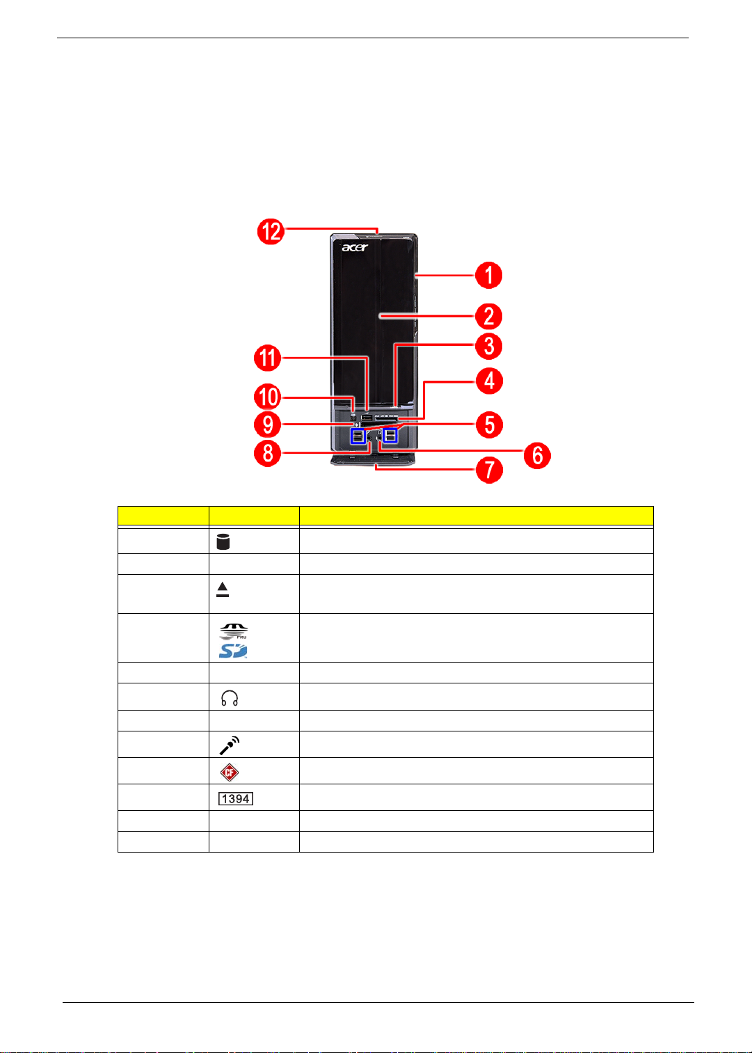
Front Panel
X3812
No. Icon Component
1 HDD activity indicator
2 Optical drive bay door
3 Drive bay door eject button
Press to open drive bay door and access the optical drive.
4 Media card reader
5 USB 2.0 ports
6 Headphone/Speaker-out/line-out jack
7 Front I/O cover
8 Microphone-in jack
9 CF I/II (CompactFlash Type I/II) slot
10 IEEE 1394 port (4-pin)
1 1 USB 2.0 port
12 Power button/power indicator
Chapter 1 5
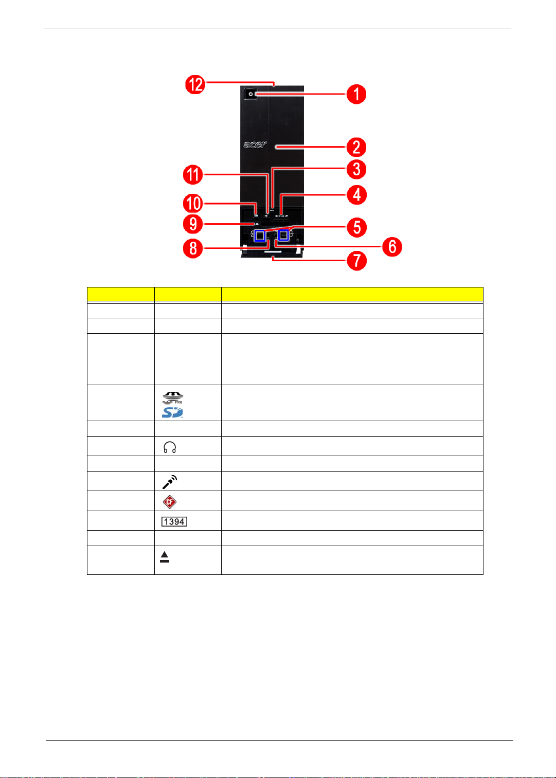
X5812
No. Icon Component
1 Power button/power indicator
2 Optical drive bay door
3 Front I/O cover open/close icon
Press beneath the icon (on the cover) to open the front I/O
cover. To close the door, flip the cover back into place, then
press the cover, beneath the icon.
4 Media card reader
5 USB 2.0 ports
6 Headphone/Speaker-out/line-out jack
7 Front I/O cover
8 Microphone-in jack
9 CF I/II (CompactFlash Type I/II) slot
10 IEEE 1394 port (4-pin)
1 1 USB 2.0 port
12 Drive bay door eject button
Press to open drive bay door and access the optical drive.
6 Chapter 1
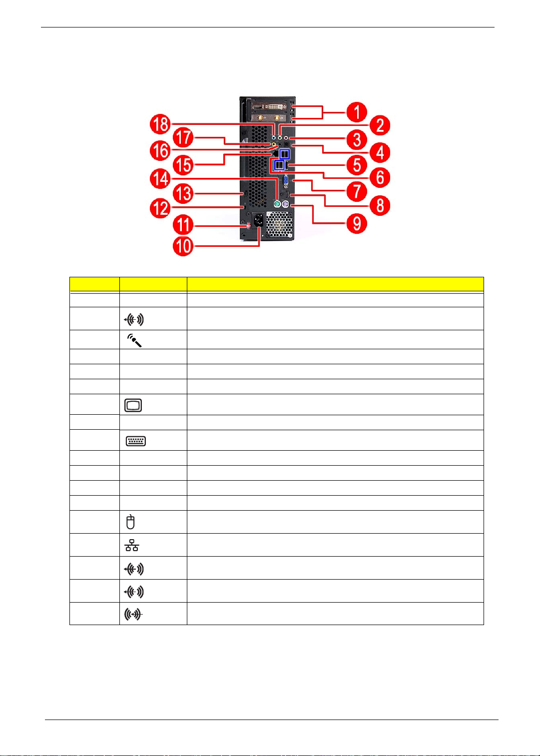
Rear Panel
No. Icon Component
1 Expansion slot (Photo shows graphics card and TV tuner card)
2 Line-out jack
3 Microphone/speaker-out/line-in jack
4S/PDIF port
5eSATA port
6 USB 2.0 ports
7 VGA monitor port
8 HDMI port
9 PS2 keyboard port
10 Power connector
1 1 Voltage selector switch
12 Lock slot
13 Key hole
14 PS2 mouse port
15 Gigabit LAN port (10/100/1000 Mbps)
16 Rear speaker/surround out jack
17 Center speaker/subwoofer jack
18 Audio in or side speaker jack
Chapter 1 7
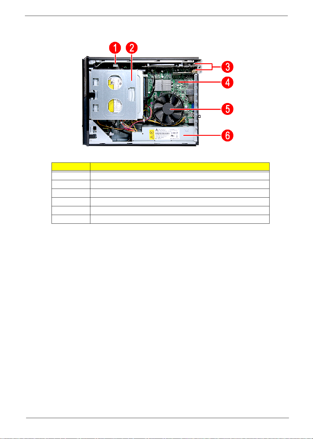
Internal Components
No. Component
1 HDD drive
2 Optical drive
3 Expansion cards
4 Mainboard
5 Heat sink fan assembly
6 Power supply
8 Chapter 1
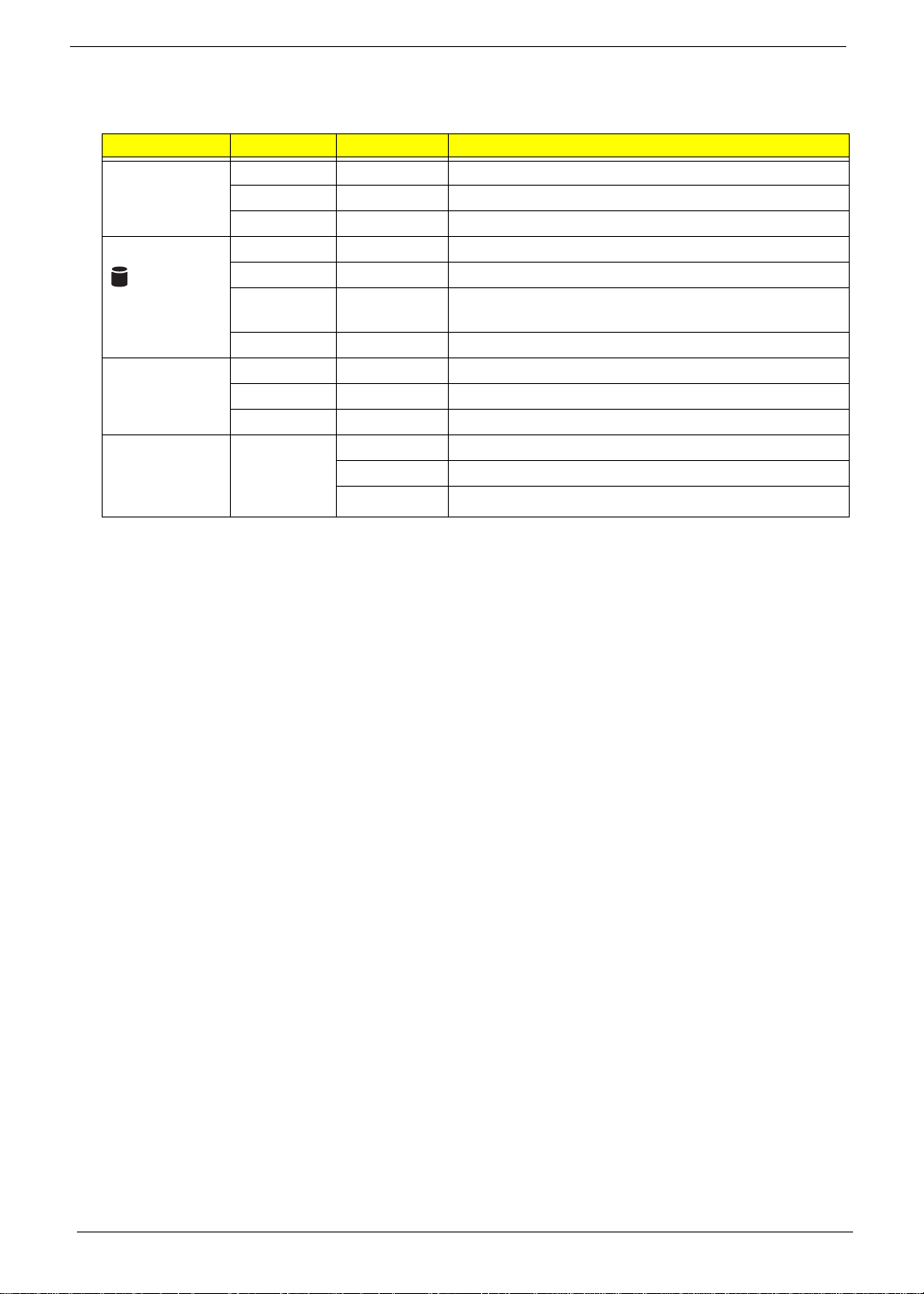
System LED Indicators
This section describes the different system LED indicators.
LED indicator Color LED status Description
Power Green On The system has AC power and is powered on.
Green Blinking The system is in standby mode.
— Off System is not powered on.
HDD activity Green On HDD is installed and functioning correctly.
Green Blinking Ongoing HDD activity.
Green/
Amber
Flashing HDD is rebuilding data.
Amber On HDD failure
LAN port
network speed
LED (left)
Amber On GbE link network access
Green On 100 Mbps link network access
— Off 10 Mbps link network access
LAN port
network
connection LED
(right)
Green On Active network link
Blinking Ongoing network data activity
Off Off-line network

Chapter 2 9
CMOS Setup Utility
CMOS setup is a hardware configuration program built into the system ROM, called the complementary metal-
oxide semiconductor (CMOS) Setup Utility. Since most systems are already properly configured and
optimized, there is no need to run this utility. You will need to run this utility under the following conditions.
• When changing the system configuration settings
• When redefining the communication ports to prevent any conflicts
• When modifying the power management configuration
• When changing the password or making other changes to the security setup
• When a configuration error is detected by the system and you are prompted ("Run Setup"
message) to make changes to the CMOS setup
NOTE: If you repeatedly receive Run Setup messages, the battery may be bad. In this case, the system
cannot retain configuration values in CMOS. Ask a qualified technician for assistance.
CMOS setup loads the configuration values in a battery-backed nonvolatile memory called CMOS RAM. This
memory area is not part of the system RAM which allows configuration data to be retained when power is
turned off.
Before you run the CMOS Setup Utility, make sure that you have saved all open files. The system reboots
immediately after you close the Setup.
NOTE: CMOS Setup Utility will be simply referred to as “BIOS”, "Setup", or "Setup utility" in this guide.
The screenshots used in this guide display default system values. These values may not be the same
those found in your system.
System Utilities
Chapter 2

10 Chapter 2
Entering CMOS setup
1. Turn on the computer and the monitor.
If the computer is already turned on, close all open applications, then restart the computer.
2. During POST, press Delete.
If you fail to press Delete before POST is completed, you will need to restart the computer.
The Setup Main menu will be displayed showing the Setup’s menu bar. Use the left and right arrow keys
to move between selections on the menu bar.
Navigating Through the Setup Utility
Use the following keys to move around the Setup utility.
• Left and Right arrow keys – Move between selections on the menu bar.
• Up and Down arrow keys – Move the cursor to the field you want.
• PgUp and PgDn keys – Move the cursor to the previous and next page of a multiple page menu.
• Home – Move the cursor to the first page of a multiple page menu.
• End – Move the cursor to the last page of a multiple page menu.
• + and - keys – Select a value for the currently selected field (only if it is user-confi g u rab l e ). Press
these keys repeatedly to display each possible entry, or the Enter key to choose from a pop-up
menu.
NOTE: Grayed-out fields are not user-configurable.
• Enter key – Display a submenu screen.
NOTE: Availability of submenu screen is indicated by a (>).
• Esc – If you press this key:
• On one of the primary menu screens, the Exit menu displays.
• On a submenu screen, the previous screen displays.
• When you are making selections from a pop-up menu, closes the pop-up without making a
selection.
• F1 – Display the General Help panel.
• F9 – Press to load optimized default system values.
• F10 – Save changes made the Setup and close the utility.
Chapter 2 11
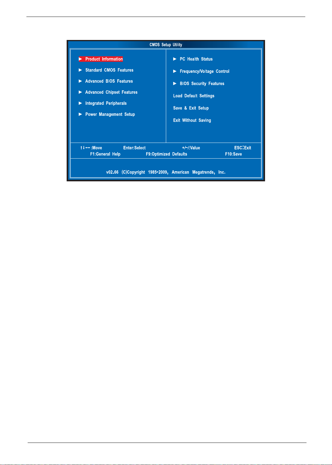
Setup Utility Menus
The Setup Main menu includes the following main setup categories.
• Product Information
• Standard CMOS Features
• Advanced BIOS Features
• Advanced Chipset Features
• Integrated Peripherals
• Power Management Setup
• PC Health Status
• Frequency/Voltage Control
• BIOS Security Features
• Load Default Settings
• Save & Exit Setup
• Exit Without Saving
In the descriptive table followi n g ea ch of th e me nu s cre en sh ots, settings in boldface are the default and
suggested settings.
12 Chapter 2
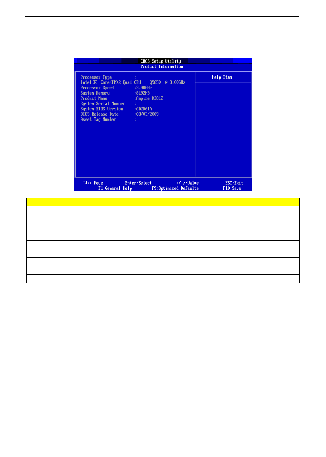
Product Information
The Product Information menu displays basic information about the system. These entries are for your
reference only and are not user-configurable.
Parameter Description
Processor Type Type of CPU installed on the system.
Processor Speed Speed of the CPU installed on the system.
System Memory Total size of system memory installed on the system.
System Manufacturer Name of the manufacturer of this system.
Product Name Product name of the system.
System Serial Number Serial number of the system.
System BIOS Version Version number of the BIOS setup utility.
BIOS Release Date Date when the BIOS setup utility was released
Asset Tag Number Asset tag number of this system.
Chapter 2 13
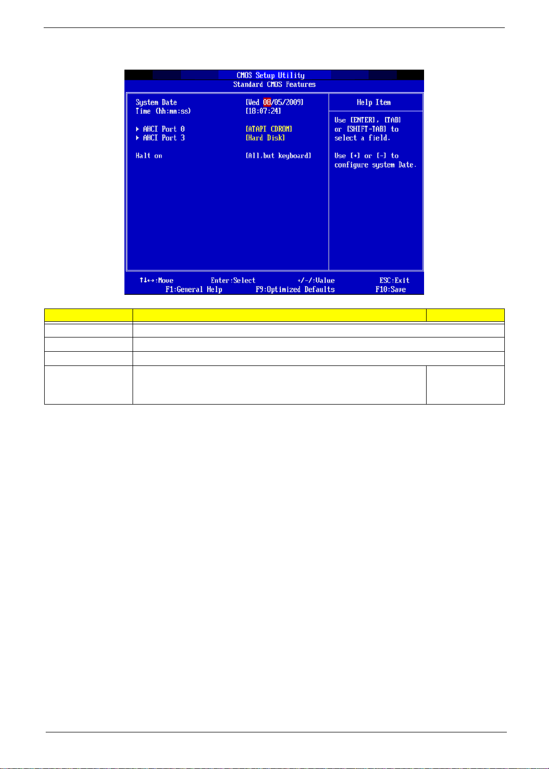
Standard CMOS Features
Parameter Description Option
System Date Set the date following the weekday-month-day-year format.
System Time Set the system time following the hour-minute-second format.
AHCI Port 0/1/2/3 Displays the status of auto detection of the AHCI device.
Halt On Determines whether the system will stop for an error during the POST. All, But Keyboard
No Errors
All Errors
14 Chapter 2
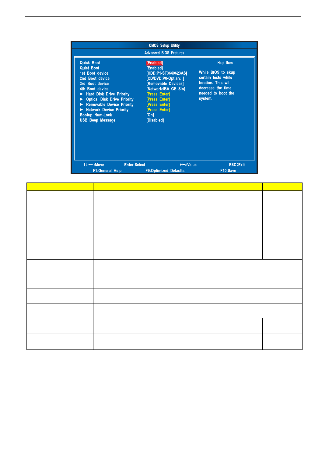
Advanced BIOS Features
Parameter Description Option
Quick Boot Allows you to decrease the time it takes to boot the computer by shortening
or skipping certain standard booting process.
Enabled
Disabled
Quiet Boot When enabled, the BIOS splash screen displays during startup.
When disabled, the diagnostic screen displays during startup.
Enabled
Disabled
1st/2nd/3rd/4th Boot Device Specifies the boot order from the available devices. Hard Disk
CD^DVD
Removable
Device
LAN
Hard Disk Drive Priority Press Enter to access the Hard Disk Drive Priority submenu and specify the boot device
priority sequence from available hard drives.
Optical Disk Drive Priority Press Enter to access the Optical Disk Drive Priority submenu and specify the boot device
priority sequence from available CD/DVD drives.
Removable Device Priority Press Enter to access the Removable Device Prio rity submenu and specify the boot device
priority sequence from available removable drives.
Network Device Priority Press Enter to access the Network Device Priority submenu and specify the boot sequence
from available network devices.
Bootup Num-Lock Selects power on state for Num Lock. On
Off
USB Beep Message Enables or disables BIOS to display error beeps or messages during USB
device enumeration.
Disabled
Enabled
Chapter 2 15
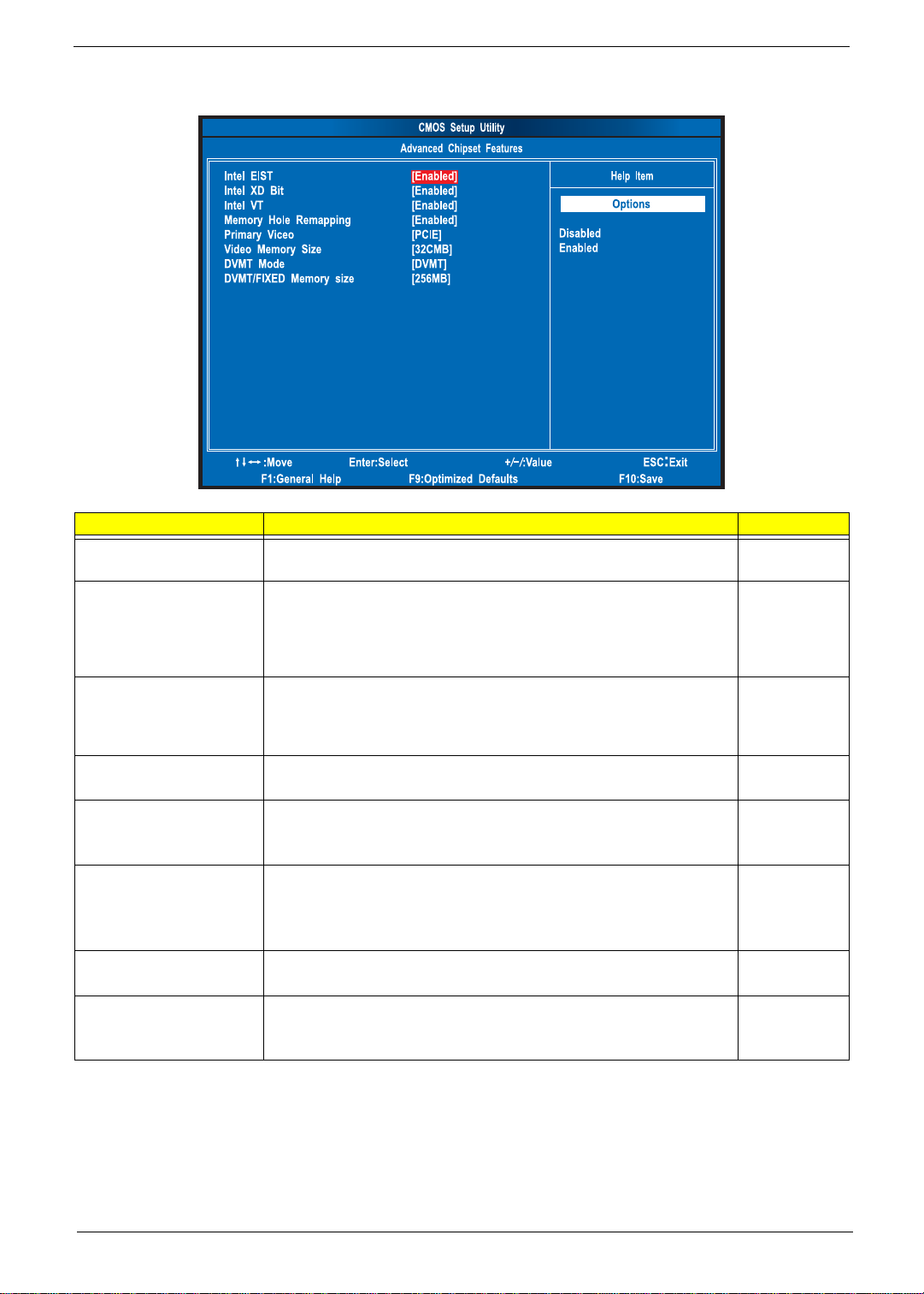
Advanced Chipset Features
Parameter Description Option
Intel EIST When enabled, this feature allows the OS to reduce power consumption.
When disabled, the system operates at maximum CPU speed.
Enabled
Disabled
Intel XD Bit When enabled, the processor disables code execution wh en a worm
attempts to insert a code in the buffer preventing damage and worm
propagation.
When disabled, the processor forces the Execute Disable (XD) Bit feature
flag to always return to 0.
Enabled
Disabled
Intel VT Enables or disables the Virtualization Technology (VT) availability. If
enabled, a virtual machine manager (VMM) can utilize the additional
hardware virtualization capabilities provided by this technology.
Note: A full reset is required to change the setting.
Enabled
Disabled
Memory Hole Remapping Enables or disables remapping of overlapped PCI memory above the total
physical memory.
Enabled
Disabled
Primary Video Select a graphic controller as a primary boot device. Auto
PCIE
Onboard VGA
Video Memory Size Select the amout of system memory used by the Intel graphics device. 32 MB
64 MB
128 MB
Disabled
DVMT Mode Select a video memory mode. DVMT
Fixed
DVMT/Fixed Memory Size Select a video memory size. 256 MB
128 MB
Maximum
16 Chapter 2
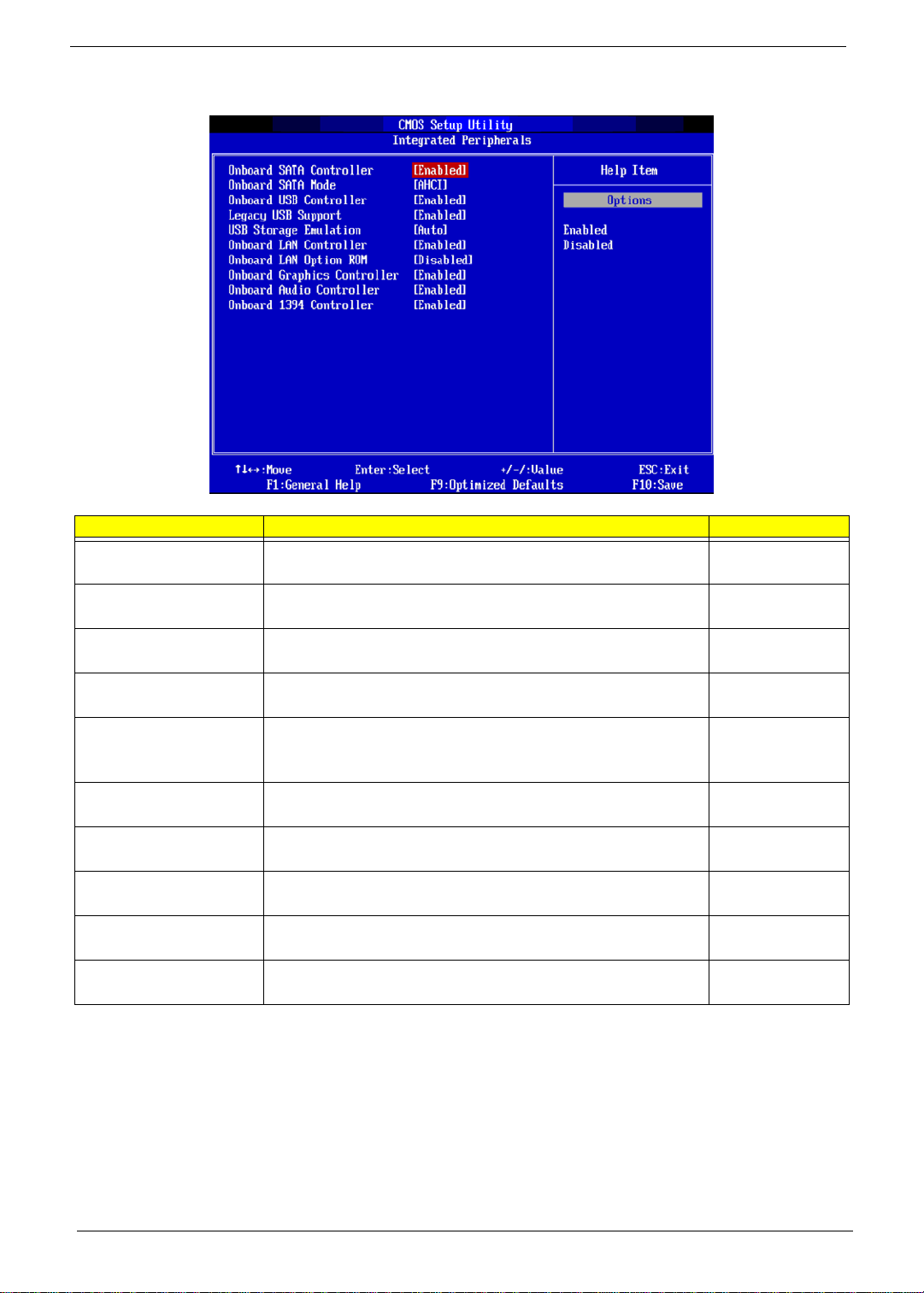
Integrated Peripherals
Parameter Description Option
Onboard SATA Controller Enables or disables the onboard SATA controller. Enabled
Disabled
Onboard SATA Mode Select an operating mode for the onboard SATA. AHCI
Native IDE
Onboard USB Controller Enables or disables the onboard USB controller. Enabled
Disabled
Legacy USB Support Enables or disables support for legacy USB devices. Enabled
Disabled
USB Storage Emulation When set to Auto, USB devices less than 2 GB will be emulated as
Floppy and remaining as HDD. Forced HDD option can be used to
force a HDD formatted drive to boot as FDD.
Auto
Floppy
Hard Disk
Onboard LAN Controller Enables or disables the onboard LAN controller. Enabled
Disabled
Onboard LAN Option ROM Enables or disables the load of embedded option ROM for onboard
network controller.
Disabled
Enabled
Onboard Graphics
Controller
Enables or disables the onboard graphics controller. Enabled
Disabled
Onboard Audio Controller Enables or disables the onboard audio controller. Enabled
Disabled
Onboard 1394 Controller Enables or disables the onboard 1394 controller. Enabled
Disabled
Chapter 2 17
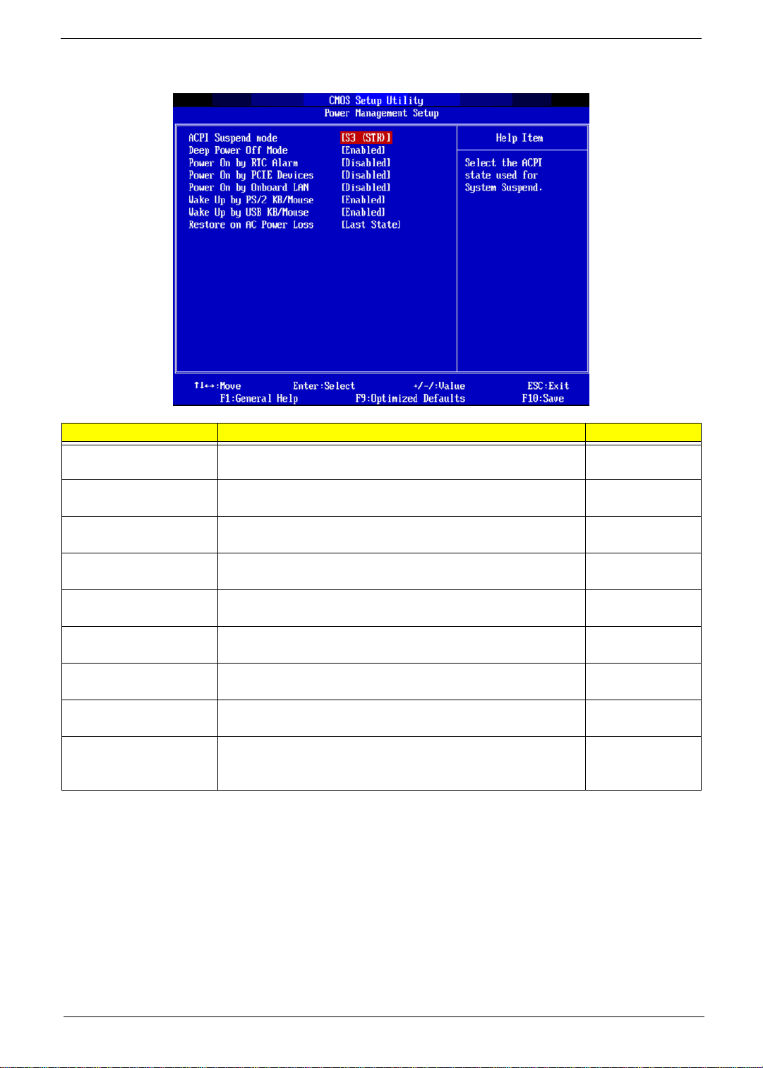
Power Management Setup
Parameter Description Option
ACPI Aware O/S Enables or disables the Advanced Configuration and Power
Management (ACPI) function.
Enabled
Disabled
ACPI Suspend Mode Select an ACPI state. S3 (STR)
S1 (POS)
Deep Power Off Mode Enables or disables deep power off mode function. Enabled
Disabled
Power On by RTC Alarm Enables or disables real time clock (RTC) to generate a wake event. Disabled
Enabled
Power On by PCIE Devices Enables or disables to wake up the system from a power saving mode
through an event on PCI Express device.
Disabled
Enabled
Power On by Onboard LAN Enables or disables an onboard LAN controller to generate a wake
event.
Disabled
Enabled
Wake Up by PS/2 KB/Mouse Enables or disables to wake up the system from a power saving mode
using a PS2 keyboard or mouse.
Enabled
Disabled
Wake Up by USB KB/Mouse Enables or disables to wake up the system from a power saving mode
using a USB keyboard or mouse.
Enabled
Disabled
Restore On AC Power Loss Enables or disables the system to reboot after a power failure or
interrupt occurs.
Power Off
Power On
Last State
18 Chapter 2
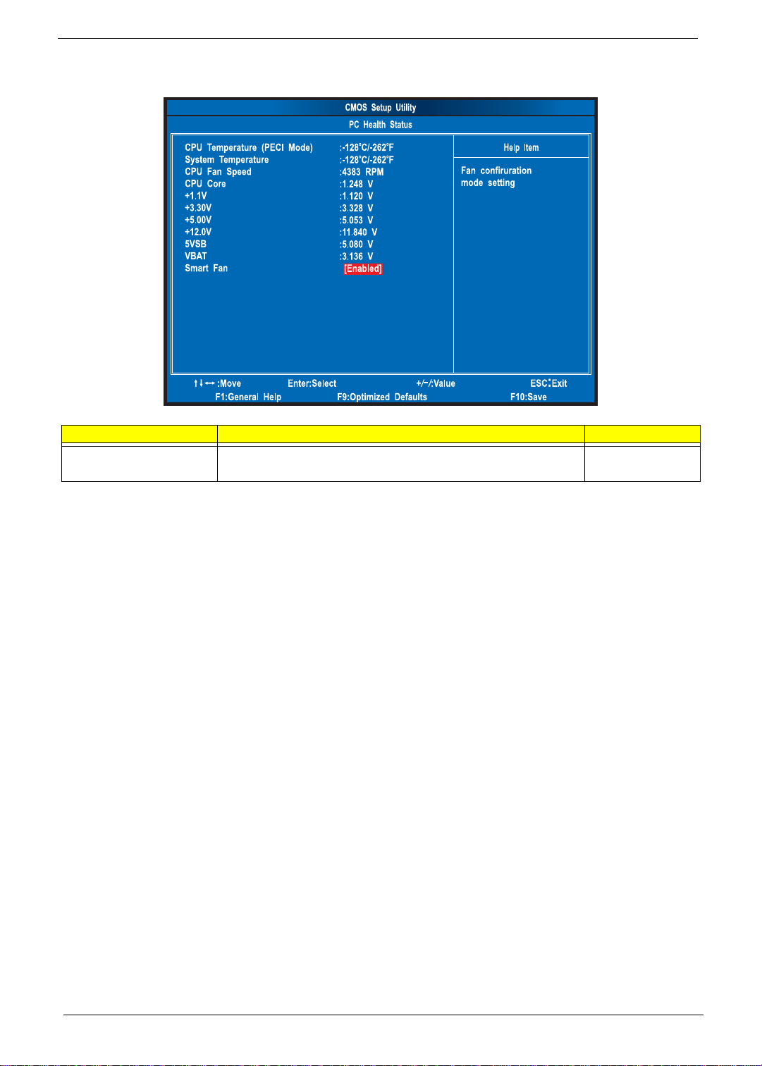
PC Health Status
Parameter Description Option
Smart FAN Enables or disables the smart system fan control function. Enabled
Disabled
Chapter 2 19
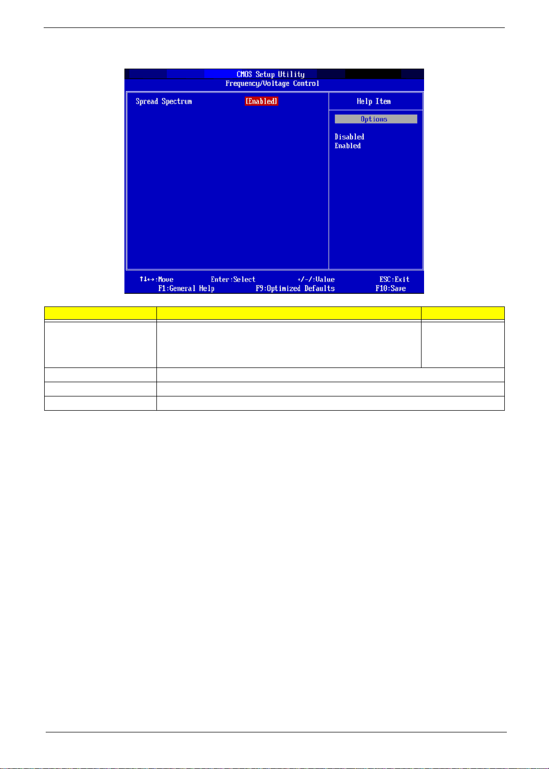
Frequency/Voltage Control
Parameter Description Option
Spread Spectrum Clock Enables or disables the reduction of the mainboard’s EMI.
Note: Remember to disable the Spread Spectrum feature if you are
overclocking. A slight jitter can introduce a temporary boost in clock
speed causing the overclocked processor to lock up.
Enabled
Disabled
Processor Configuration Press Enter to access the Processor Configuration submenu. (Not available in this model).
DRAM Configuration Press Enter to access the DRAM Configuration submenu. (Not available in this model).
Bus Configuration Press Enter to access the Bus Configuration submenu. (Not available in this model).
20 Chapter 2
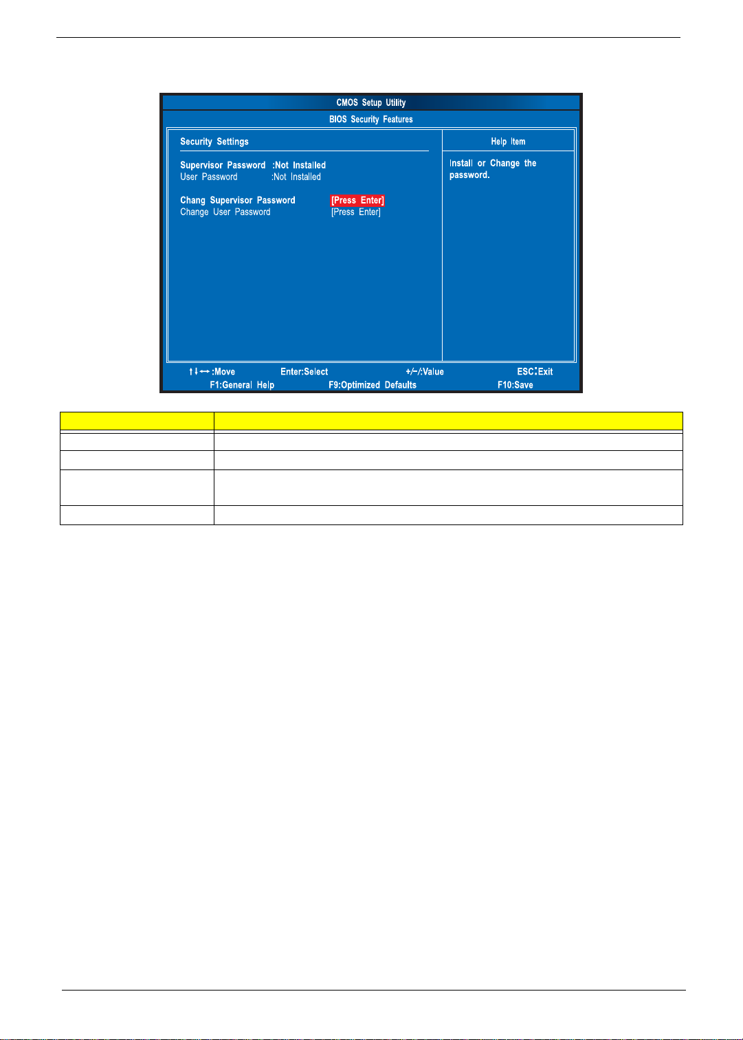
BIOS Security Features
Setting a system password
1. Use the up/down arrow keys to select a password parameter (Change Supervisor Password or Change
User Password) menu then press Enter.
A password box will appear.
2. Type a password then press Enter.
The password may consist up to six alphanumeric characters (A-Z, a-z, 0-9)
3. Retype the password to verify the first entry then press Enter again.
4. Press F10.
5. Select Yes to save the new password and close the Setup Utility.
Changing the system password
1. Use the up/down arrow keys to select password parameter (Change Supervisor Password or Change
User Password) menu then press Enter.
2. Type the original password then press Enter.
3. Type a new password then press Enter.
4. Retype the password to verify the first entry then press Enter again.
5. Press F10.
6. Select Yes to save the new password and close the Setup Utility.
Parameter Description
Supervisor Password Indicates the status of the supervisor password.
User Password Indicates the status of the user password.
Change Supervisor
Password
Supervisor password prevents unauthorized access to the BIOS Setup Utility.
Press Enter to change the Supervisor password.
Change User Password Press Enter to change the User password.

Chapter 2 21
Removing a system password
1. Use the up/down arrow keys to select password parameter (Change Supervisor Password or Change
User Password) menu then press Enter.
2. Enter the current password then press Enter.
3. Press Enter twice without entering anything in the password fields.
22 Chapter 2
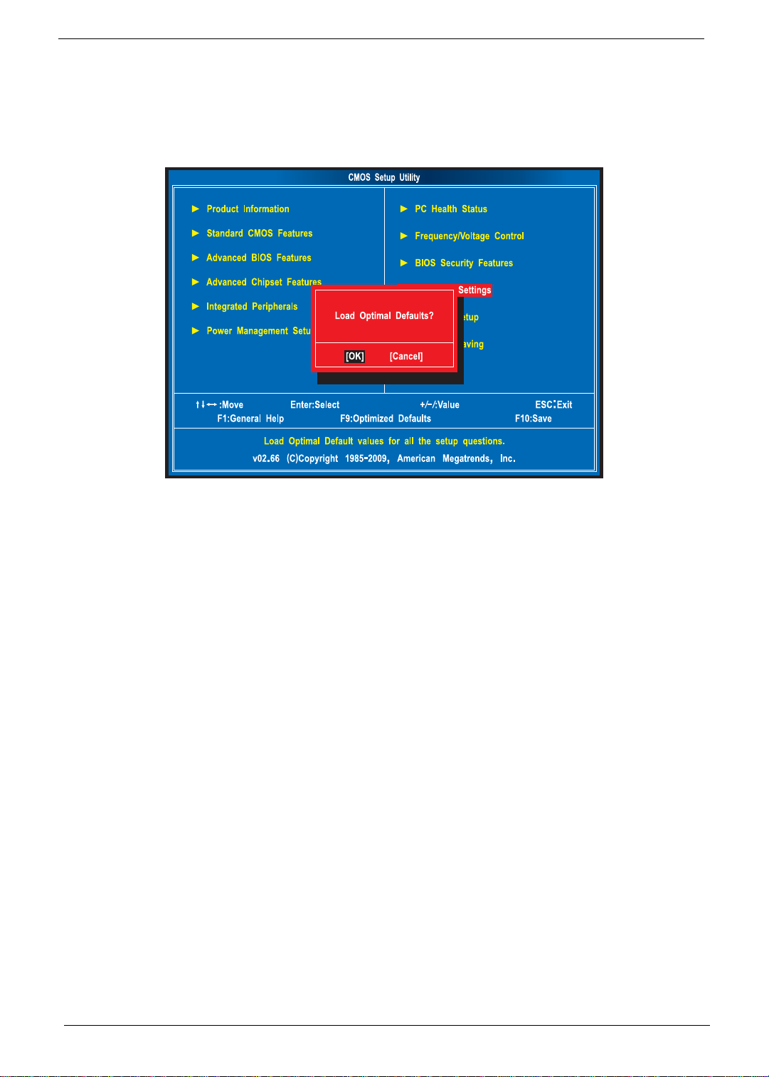
Load Default Settings
The Load Default Settings menu allows you to load the default settings for all BIOS setup parameters. Setup
defaults are quite demanding in terms of resources consumption. If you are using low-speed memory chips or
other kinds of low-performance components and you choose to load these settings, the system might not
function properly.
Loading...