


Acer
Aspire X1300/X1301
Service Guide
Service guide files and updates are available
on the ACER/CSD web; for more information,
please refer to http://csd.acer.com.tw
PRINTED IN TAIWAN

Revision History
Please refer to the table below for the updates made on ASX1300 service guide.
Date Chapter Updates
ii

Copyright
Copyright © 2009 by Acer Incorporated. All rights reserved. No part of this publication may be reproduced,
transmitted, transcribed, stored in a retrieval system, or translated into any language or computer language, in
any form or by any means, electronic, mechanical, magnetic, optical, chemical, manual or otherwise, without
the prior written permission of Acer Incorporated.
iii

Disclaimer
The information in this guide is subject to change without notice.
Acer Incorporated makes no representations or warranties, either expressed or implied, with respect to the
contents hereof and specifically disclaims any warranties of merchantability or fitness for any particular
purpose. Any Acer Incorporated software described in this manual is sold or licensed "as is". Should the
programs prove defective following their purchase, the buyer (and not Acer Incorporated, its distributor, or its
dealer) assumes the entire cost of all necessary servicing, repair, and any incidental or consequential
damages resulting from any defect in the software.
Acer is a registered trademark of Acer Corporation.
AMD, the AMD Arrow logo, AMD Athlon, AMD Phenom, AMD Sempron, and combinations thereof, are
trademarks of Advanced Micro Devices Inc.
Other brand and product names are trademarks and/or registered trademarks of their respective holders.
iv

Conventions
The following conventions are used in this manual:
SCREEN
MESSAGES
NOTE Gives additional information related to the current topic.
WARNING Alerts you to any physical risk or system damage that might result from doing
CAUTION Gives precautionary measures to avoid possible hardware or software
IMPORTANT Reminds you to do specific actions relevant to the accomplishment of
Denotes actual messages that appear on screen.
or not doing specific actions.
problems.
procedures.
v

Service Guide Coverage
This Service Guide provides you with all technical information relating to the BASIC CONFIGURATION
decided for Acer's "global" product offering. To better fit local market requirements and enhance product
competitiveness, your regional office MAY have decided to extend the functionality of a machine (e.g. add-on
card, modem, or extra memory capability). These LOCALIZED FEATURES will NOT be covered in this generic
service guide. In such cases, please contact your regional offices or the responsible personnel/channel to
provide you with further technical details.
FRU Information
Please note WHEN ORDERING FRU PARTS, that you should check the most up-to-date information available
on your regional web or channel. If, for whatever reason, a part number change is made, it will not be noted in
the printed Service Guide. For ACER-AUTHORIZED SERVICE PROVIDERS, your Acer office may have a
DIFFERENT part number code to those given in the FRU list of this printed Service Guide. You MUST use the
list provided by your regional Acer office to order FRU parts for repair and service of customer machines.
vi

Table of Contents
Table of Contents vii
System Tour 1
Features 1
Aspire X1300/X1301 Tour 3
Front Pane 3
Rear Panel 5
Internal Components 6
System LED Indicators 7
System Utilities 9
Phoenix BIOS Setup Utility 9
Entering BIOS setup 10
Navigating Through the Setup Utility 10
Setup Utility Menus 11
System Disassembly 33
Disassembly Requirements 33
Pre-disassembly Procedure 34
Main Unit Disassembly 35
External Modules Disassembly Flowchart 35
Removing the Side Panel 36
Removing the Font Bezel 37
Removing the Heat Sink Fan Assembly 38
Removing the Processor 40
Removing the Optical Drive 42
Removing the Hard Disk Drive 44
Removing the Power Supply 48
Removing the Memory Modules 51
Removing the PCI Card 53
Removing the Front I/O and Card Reader Boards 55
Removing the Mainboard 59
System Troubleshooting 61
Hardware Diagnostic Procedure 61
System Check Procedures 62
Power System Check 62
System External Inspection 62
System Internal Inspection 62
POST Error and Beep Codes 63
Online Support Information 69
System Block Diagram and Board Layout 71
System Block Diagram 71
Board Layout 72
Mainboard 72
System Jumpers 73
FRU (Field Replaceable Unit) List 75
Aspire X1300/X1301 Exploded Diagram 76
Aspire X1300/X1301 FRU List 77
Technical Specifications 87
vii

viii

Chapter 1
System Tour
Features
Below is a brief summary of the computer’s many feature:
NOTE: The features listed in this section is for your reference only. The exact configuration of the server
depends on the model purchased.
Processor
• AMD Athlon LE-1600/1620/1640 processor
• AMD Athlon X2 Dual-Core BE-2300/2350/2400 or 4200+/4400+/4800+/5000+/5200+/5600+ processor
• AMD Phenom X3 Triple-Core 8400/8450/8600/8650 processor
• AMD Phenom X4 Quad-Core 9100e/9150e/9500/9550/9600/9650 processor
• AMD Sempron LE-1250/1300 or 2100 processor
Processor (for Eup)
• AMD Athlon LE-1640/1660 processor
• AMD Athlon 2650e AM2+ processor
• AMD Athlon X2 Dual-Core 2240/2245/2250 processor
• AMD Athlon X3 Triple-Core 3400e/3405e
• AMD Athlon X4 Quad-Core 4600e/4605e
• AMD Phenom X2 Dual-Core 545/550 processor
• AMD Phenom X3 Triple-Core 700e/705e/710/720/740 processor
• AMD Phenom X4 Quad-Core 805/810/820/900e/905e/910/925/945 processor
• AMD Sempron LE-1250/1300 or Sempron Dual Core 2200/2300 processor
Chipset
• NVIDIA nForce MCP78
Memory subsystem
• Supports up to two DDR2-667 registered ECC modules
Media storage
• DVD-ROM SATA drive
• Super-Multi SATA DVD drive
• 160 GB SATA hard disk drive
Serial ATA controller
• Embedded SATA2 controller
• Two SATA ports
Networking
• One Gigabit Ethernet LAN port (RJ-45)
Chapter 1 1

PCI I/O
• One PCI Express x16 bus slot
• One PCI Express x1 bus slot
I/O ports
• Front
• Three USB 2.0 ports
• Memory Stick
• Memory Stick PRO
• Secure Digitial (SD) Card
• miniSD Card
• Headphone/speaker-out/line-out jack
• Microphone-in jack
• CFI/II (CompactFlash Type i/II) slot
• IEEE 1394 port (4-pin)
• Rear
• PS/2 keyboard port
• PS/2 mouse port
• Line-out jack
• Microphone/speaker-out/line-in jack
• Rear speaker/surround out jack
• Center speaker/subwoofer jack
• Line-in jack
• S/PDIF port
• Four USB 2.0 ports
• eSATA port
• CRT/LCD monitor port
• HDMI port
• Gigabit LAN ports
• VGA/monitor port
• Two USB 2.0 ports
• Two Ethernet LAN ports (RJ-45)
Operating system and software
• Operating system options:
• Genuine Windows Vista
• Genuine Windows Vista Home Premium (32/64-bit)
• Applications
• Acer Empowering Technology (Acer eRecovery Management)
• Acer Arcade Live
• McAfee Internet Security Suite 2008 Trial version
• Adobe Reader
• eSobi
• NTI MediaMaker
®
Ultimate (32/64-bit)
Power supply
• 220-watts (115/230 Vac) power supply/220-watts (115/230 Vac) power supply Eup
2 Chapter 1
Aspire X1300/X1301 Tour
This section is a virtual tour of the ASX1300 system’s interior and exterior components.
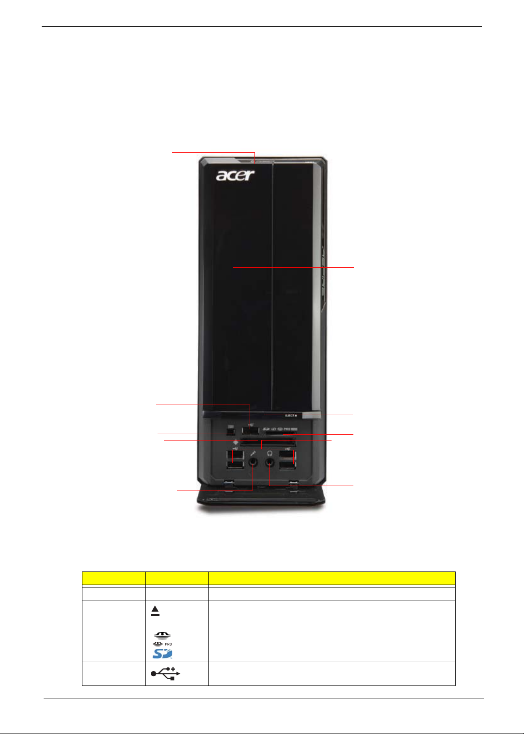
Front Pane
J
B
E
I
H
G
Item Icon Component
B Drive bay door
C Drive bay door eject button
Press to open drive bay door and access the optical drive.
D Media card reader
E USB 2.0 ports
C
D
E
F
Chapter 1 3
Item Icon Component
F Headphone/Speaker-out/line-out jack
G Microphone-in jack
H CF I/II (CompactFlash Type I/II) slot
I IEEE 1394 port (4-pin)
J Power/sleep button
4 Chapter 1
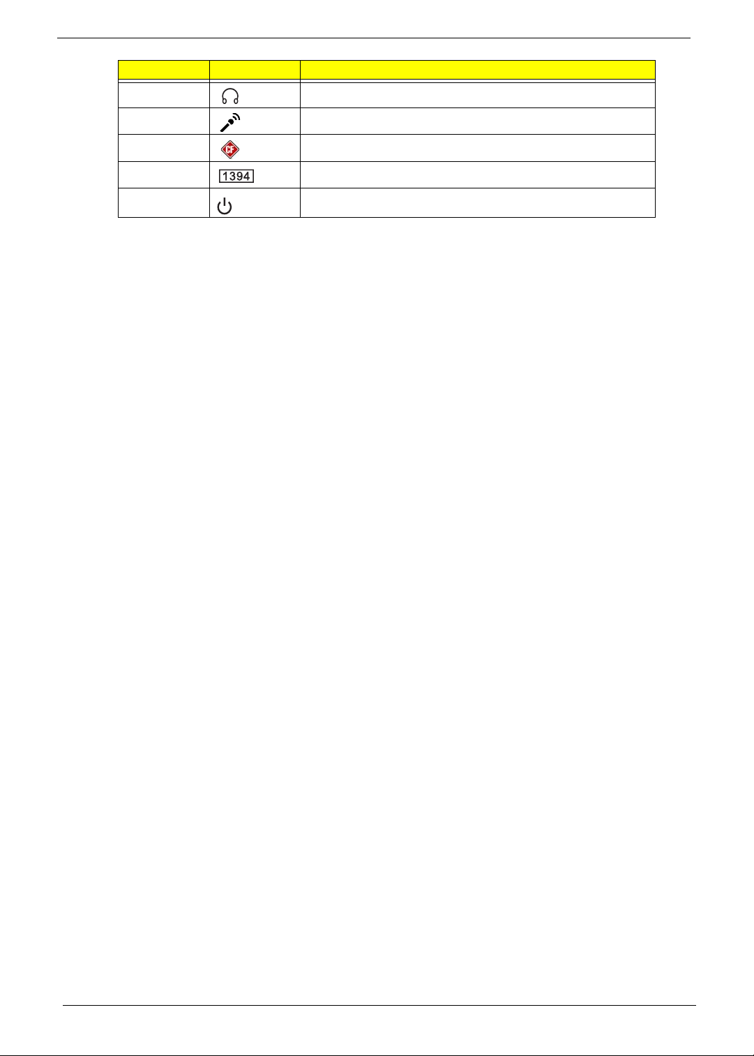
Rear Panel
A
Q
P
O
N
M
E
L
K
J
Item Icon Component
A Expansion slot (Photo shows graphics card and network/modem card)
B Line-out jack
C Microphone/speaker-out/line-in jack
B
C
D
E
F
G
H
I
D SPDIF S/PDIF port
E USB 2.0 ports
F ESATA eSATA port
G CRT/LCD monitor port
H HDMI HDMI port
I PS2 keyboard port
J Power connector
K Voltage selector switch
L PS2 mouse port
M Gigabit LAN port (10/100/1000 Mbps)
N Rear speaker/surround out jack
O Keyhole
P Center speaker/subwoofer jack
Q Line-in jack
Chapter 1 5
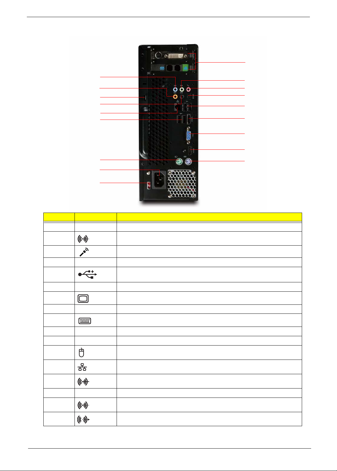
Internal Components
Item Component
A Expansion card
B Mainboard
C Optical drive
D Heat sink fan assembly
E Power supply
A
B
C
D
E
6 Chapter 1
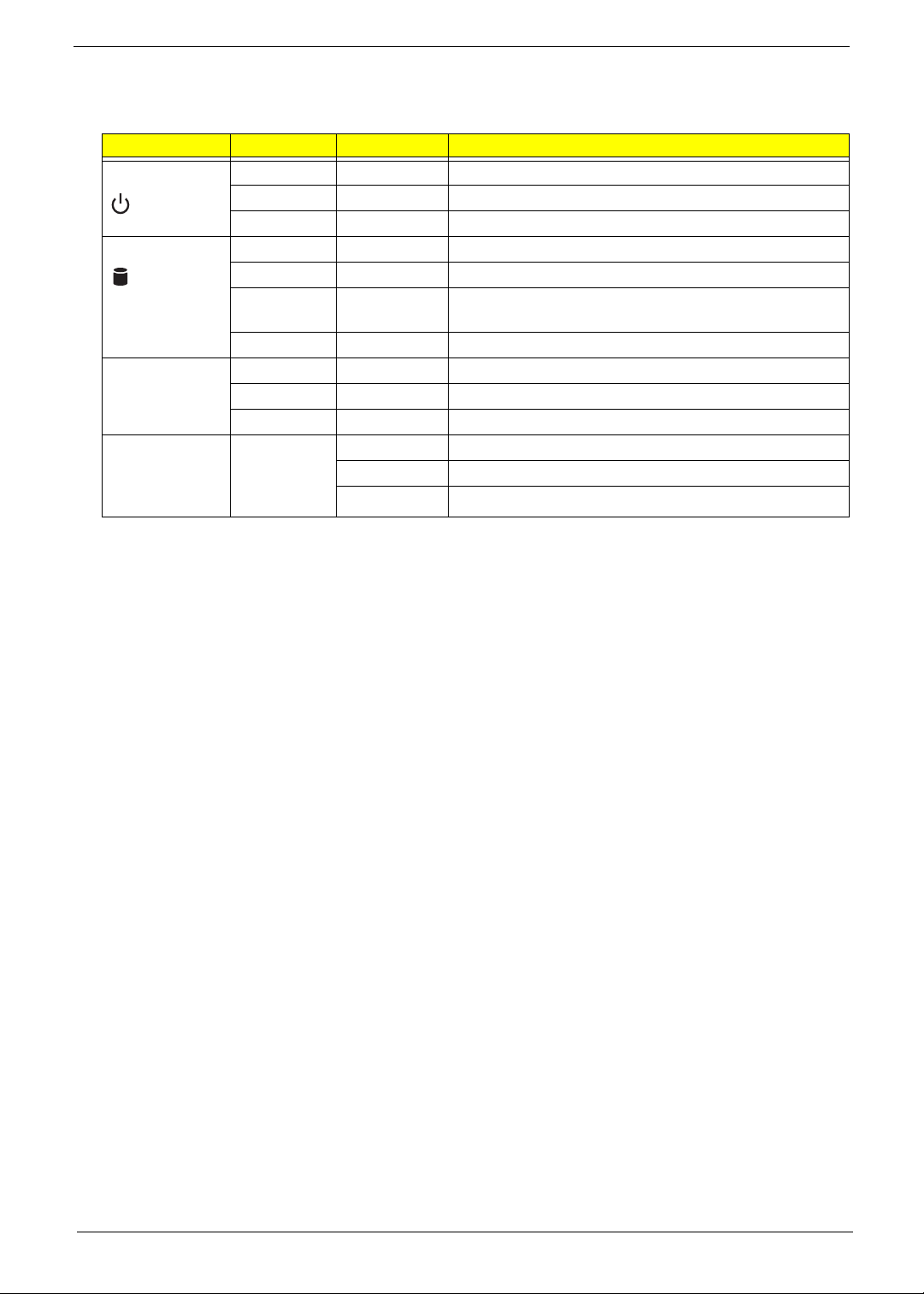
System LED Indicators
This section describes the different system LED indicators.
LED indicator Color LED status Description
Power Green On The system has AC power and is powered on.
Green Blinking The system is in standby mode.
— Off System is not powered on.
HDD activity Green On HDD is installed and functioning correctly.
Green Blinking Ongoing HDD activity.
LAN port
network speed
LED (left)
LAN port
network
connection LED
(right)
Green/
Amber
Amber On HDD failure
Amber On GbE link network access
Green On 100 Mbps link network access
— Off 10 Mbps link network access
Green On Active network link
Flashing HDD is rebuilding data.
Blinking Ongoing network data activity
Off Off-line network
Chapter 1 7

8 Chapter 1

Chapter 2
System Utilities
Phoenix BIOS Setup Utility
BIOS setup is a hardware configuration program built into the system's Basic Input/Output System (BIOS).
Since most systems are already properly configured and optimized, there is no need to run this utility. You will
need to run this utility under the following conditions.
• When changing the system configuration settings
• When redefining the communication ports to prevent any conflicts
• When modifying the power management configuration
• When changing the password or making other changes to the security setup
• When a configuration error is detected by the system and you are prompted ("Run Setup"
message) to make changes to the BIOS setup
NOTE: If you repeatedly receive Run Setup messages, the battery may be bad. In this case, the system
cannot retain configuration values in CMOS. Ask a qualified technician for assistance.
BIOS setup loads the configuration values in a battery-backed nonvolatile memory called CMOS RAM. This
memory area is not part of the system RAM which allows configuration data to be retained when power is
turned off.
Before you run the PhoenixBIOS Setup Utility, make sure that you have saved all open files. The system
reboots immediately after you close the Setup.
NOTE: PhoenixBIOS Setup Utility will be simply referred to as "Setup" or "Setup utility" in this guide.
The screenshots used in this guide display default system values. These values may not be the same
those found in your system.
Chapter 2 9

Entering BIOS setup
1. Turn on the server and the monitor.
If the server is already turned on, close all open applications, then restart the server.
2. During POST, press Delete.
If you fail to press Delete before POST is completed, you will need to restart the server.
The Setup Main menu will be displayed showing the Setup’s menu bar. Use the left and right arrow keys
to move between selections on the menu bar.
Navigating Through the Setup Utility
Use the following keys to move around the Setup utility.
• Left and Right arrow keys – Move between selections on the menu bar.
• Up and Down arrow keys – Move the cursor to the field you want.
• PgUp and PgDn keys – Move the cursor to the previous and next page of a multiple page menu.
• Home – Move the cursor to the first page of a multiple page menu.
• End – Move the cursor to the last page of a multiple page menu.
• + and - keys – Select a value for the currently selected field (only if it is user-configurable). Press
these keys repeatedly to display each possible entry, or the Enter key to choose from a pop-up
menu.
NOTE: Grayed-out fields are not user-configurable.
• Enter key – Display a submenu screen.
NOTE: Availability of submenu screen is indicated by a (>).
• Esc – If you press this key:
q On one of the primary menu screens, the Exit menu displays.
q On a submenu screen, the previous screen displays.
q When you are making selections from a pop-up menu, closes the pop-up without making a
selection.
• F1 – Display the BIOS setup General Help panel.
• F5 – Press to load previous default system values.
• F6 – Press to load fail-safe default system values.
• F7 – Press to load optimized default system values.
• F10 – Save changes made the Setup and close the utility.
10 Chapter 2

Setup Utility Menus
The tabs on the Setup menu bar correspond to the six primary BIOS Setup menus, namely:
• Product Information
• Standard CMOS Features
• Advanced BIOS Features
• Advanced Chipset Features
• Integrated Peripherals
• Power Management Setup
• PnP/PCI Configurations
• PC Health Status
• Load Default Settings
• Set Supervisor Password
• Set User Password
• Save & Exit Setup
• Exit Without Saving
In the descriptive table following each of the menu screenshots, settings in boldface are the default and
suggested settings.
Chapter 2 11
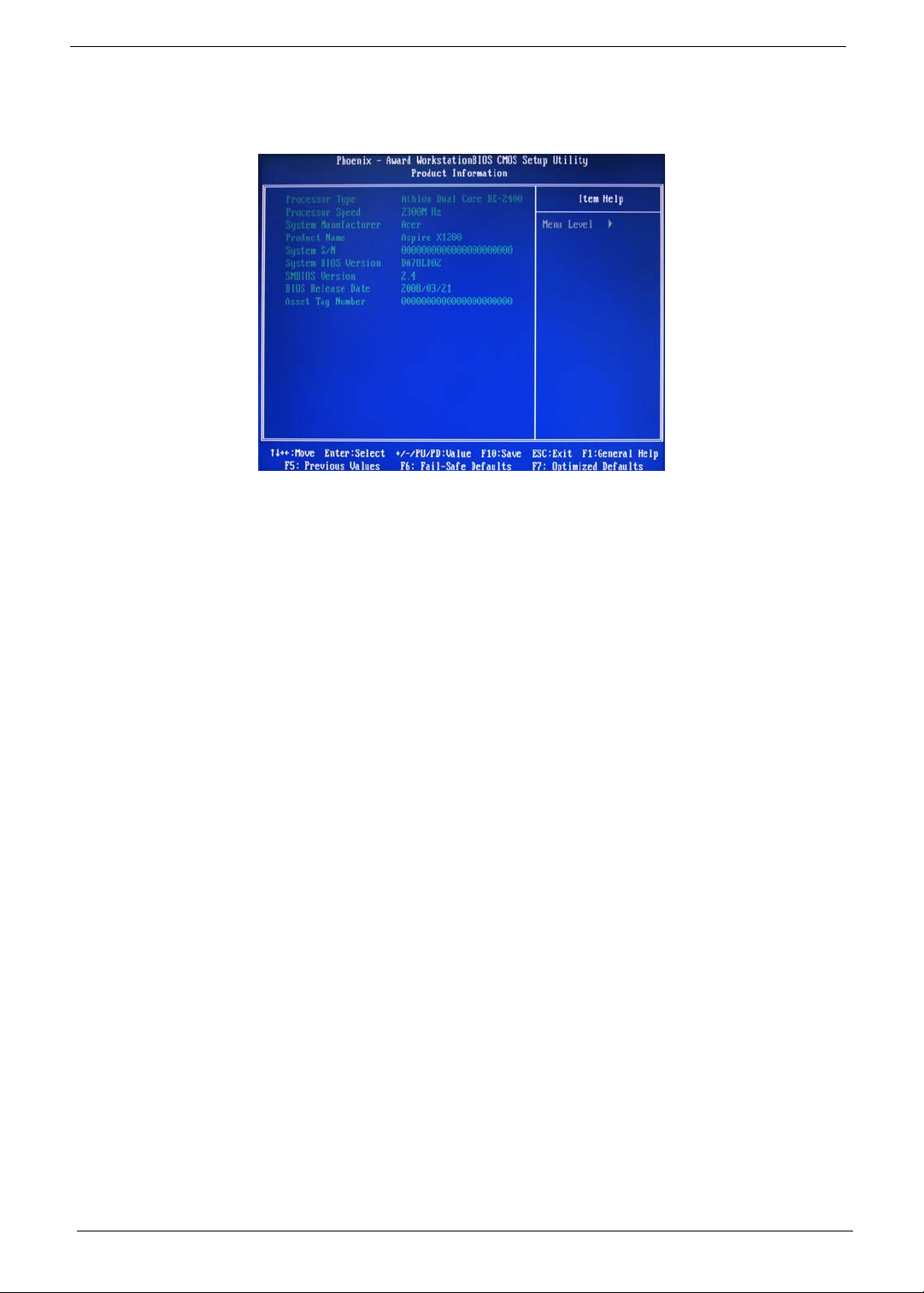
Product Information
The Product Information menu displays basic information about the system. These entries are for your
reference only and are not user-configurable.
12 Chapter 2
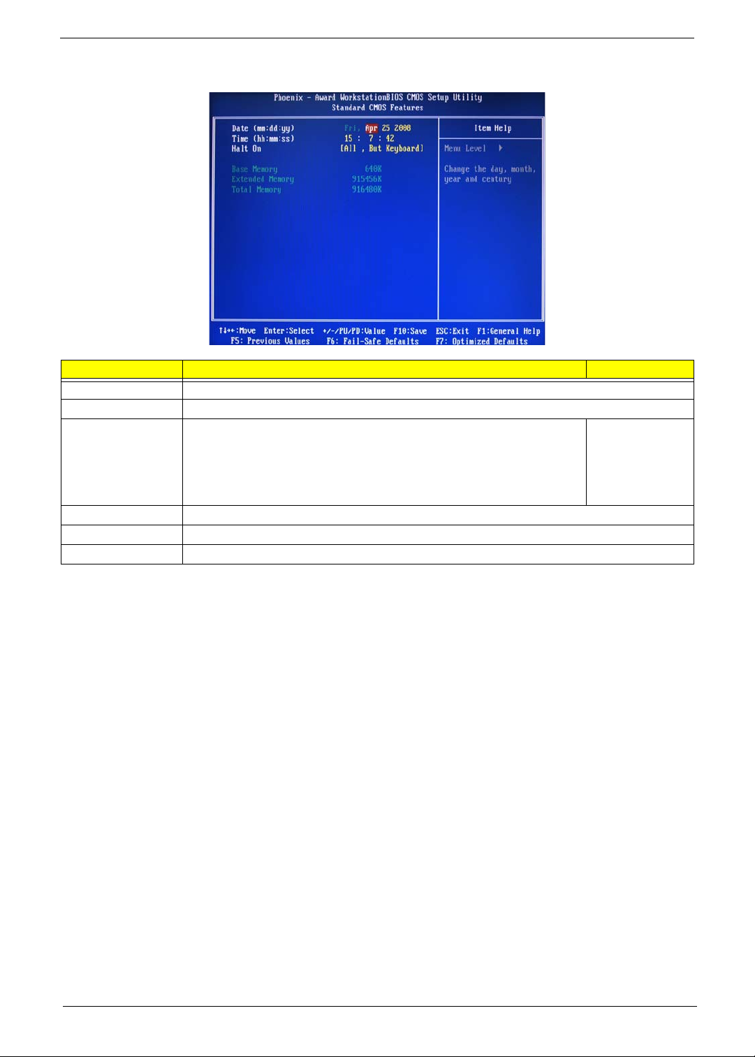
Standard CMOS Features
Parameter Description Option
Date Set the date following the weekday-month-day-year format.
Time Set the system time following the hour-minute-second format.
Halt On Determines whether the system will stop for an error during the POST. All, But Keyboard
No Errors
All Errors
All, But Diskette
All, But Disk/Key
Base Memory Also called conventional memory. Typically, 640 KB will be reserved for the MS-DOS OS.
Extended Memory Total size of extended memory detected during POST
Total Memory Total size of system memory detected during POST
Chapter 2 13

Advanced BIOS Features
Parameter Description Option
CPU Feature Press Enter to configure the CPU Virtualization and AMD K8 Cool and Quiet Control features.
Hard Disk Boot Priority Press Enter to select hard disk boot device priority.
Virus Warning Specifies the virus warning feature for IDE hard disk boot sector protection.
If enabled, BIOS will show a warning message on the screen or an alarm
beep when someone attempts to write data into this area.
CPU Internal Cache Enables or disables CPU internal cache. Enabled
External Cache Enables or disables internal cache. Enabled
Quick Power On Self Test Allows the system to skip certain test while booting. This will decrease the
First/Second/Third/Fourth
Boot Device
Boot Up Floppy Seek Enables or disables floppy drive testing to determine whether they have 40
Boot Up NumLock Status Selects power on state for Num Lock. On
Gate A20 Option When set to fast, the motherboard chipset controls the operation of Gate
Typematic Rate Setting When enabled, you can manually adjust the settings using the two typematic
Typematic Rate (Chars/Sec) Rate at which the keyboard will repeat the keystroke if you press it
Typematic Delay (MSec) Delay, in Msec, before the keyboard automatically repeats the keystroke that
time needed to boot the system.
Specifies the boot order from the available devices. CDROM, Hard
to 80 tracks.
A20. But when set to normal, a pin in the keyboard controller controls Gate
A20.
controls (Typematic Rate and Typematic Rate Delay). If disabled, the BIOS
will use the default setting.
continuously.
you have pressed continuously.
Disabled
Enabled
Disabled
Disabled
Enabled
Disabled
Disk, NVIDIA
Boot Age,
Floppy,
ZIP, USB-FDD,
USB-ZIP, USBCDROM, USBHDD, Legacy
LAN, Disabled
Disabled
Enabled
Off
Fast
Normal
Disabled
Enabled
6, 8, 10, 12, 15,
20, 24, 30
250, 500, 750,
1000
14 Chapter 2
Parameter Description Option
Security Option When set to system, BIOS will ask for the password each time the system
MPS Version Control For
OS
OS Select For DRAM > 64 MBSelect OS/2 if the system is running OS/2 operating system and the system
Full Screen Logo Show Enables or disables the display of the full screen boot logo. Enabled
Small Logo (EPA) Show Enables or disables the display of the EPA logo. Disabled
boots up.
If set to setup, the password is only required for access into the BIOS setup
menus.
Specifies the version of the Multiprocessor Specification (MPS) that the
mainboard will use.
memory is more than 64 MB in size.
Setup
System
1.4
1.1
Non-OS/2
OS/2
Disabled
Enabled
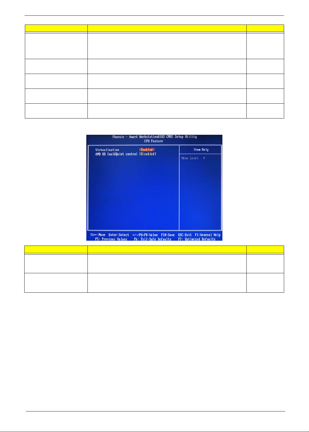
CPU Feature
Parameter Description Option
Virtualization Select whether to enable or disable the AMD Virtualization Technology (VT)
function. VT allows a single platform to run multiple operating systems in
independent partitions.
AMD K8 Cool&Quiet control When set to auto, the AMD Cool’n’Quiet driver dynamically adjust the CPU
clock and VIA to reduce heat output from your computer and its power
consumption.
Enabled
Disabled
Disabled
Auto
Chapter 2 15
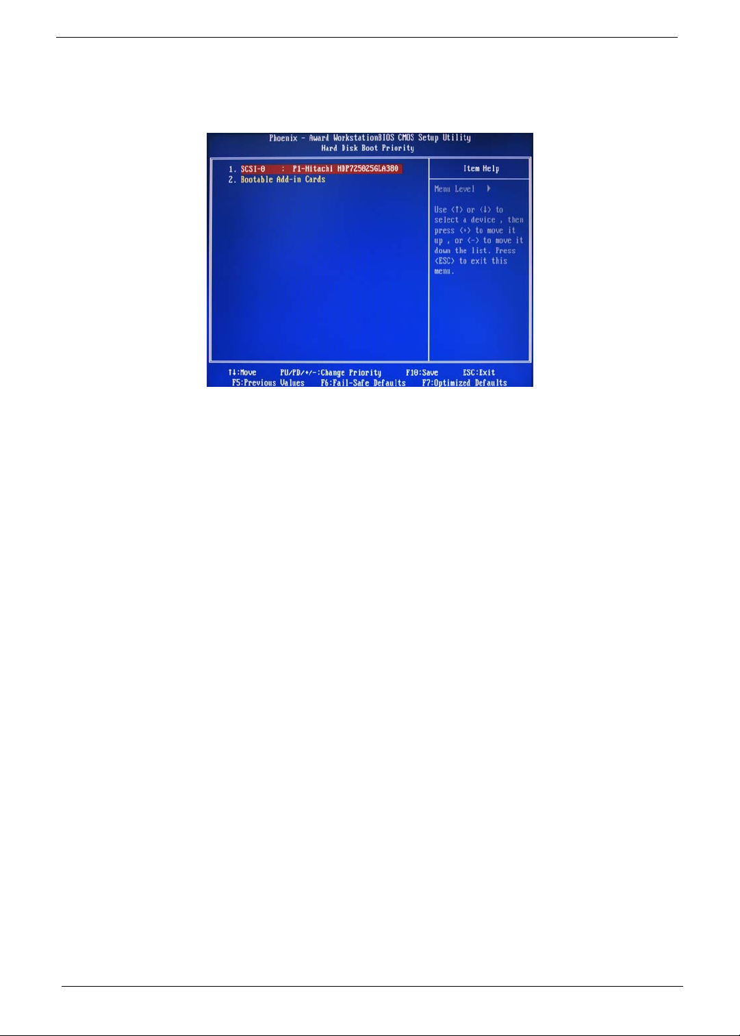
Hard Disk Boot Priority
The Hard Disk Boot Priority submenu allows you to specify the sequence of loading the OS from the installed
hard drives. Use the up or down arrow key to select a hard drive, then press the <+> key or the <-> key to
move it up or down on the list. l
16 Chapter 2
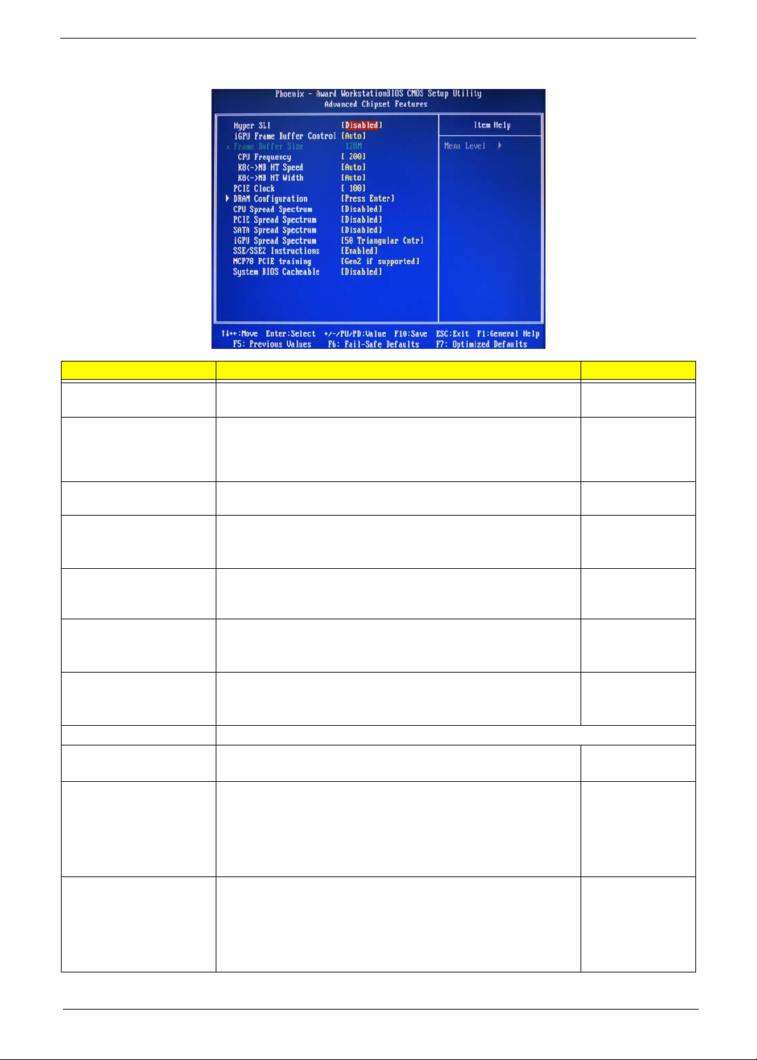
Advanced Chipset Features
Parameter Description Option
Hyper SLI Enable or disable the Scalable Link Interface (SLI) technology. Disabled
Enabled
iGPU Frame Buffer Control When set to auto, BIOS will automatically setup the frame buffer size.
When set to manual, you can set the frame buffer size. Frame buffer
size is the total amount of system memory allocated solely for the
onboard graphics controller.
Frame Buffer Size This parameter can be configured if the iGPU Frame Buffer Control is
set to Manual.
CPU Frequency Sets processor minimum and maximum frequency. 200
KB<->NB HT Speed Controls the physical speed of the processor to the Northbridge HT link. Auto
KB<->NB HT Width Controls the processor to the Northbridge link bandwidth. Auto
PCIE Clock Sets the PCI Express clock frequency. 100
DRAM Configuration Press Enter to configure memory timing and operation settings.
CPU Spread Spectrum Allows you to reduce the EMI of the front side bus by modulating the
signals it generates so that the spikes are reduced to flatter curves.
PCIE Spread Spectrum Allows you to reduce the EMI of the PCI Express bus by modulating the
signals it generates so that the spikes are reduced to flatter curves.
When set to down spread, the chipset modulates the PCI Express bus'
baseline signal downwards by a small amount.
When set to disabled, the chipset disables any modulation of the PCI
Express bus' baseline signal.
SATA Spread Spectrum Allows you to reduce the EMI of the SATA bus by modulating the
signals it generates so that the spikes are reduced to flatter curves.
When set to down spread, the chipset modulates the SATA bus'
baseline signal downwards by a small amount.
When set to disabled, the chipset disables any modulation of the SATA
bus' baseline signal.
Auto
Manual
64, 16, 32, 128,
256 MB
Minimum 100
Maximum 500
200, 400, 600, 800
MHz, 1 GHz
Up 8/16
Down 8/16
Minimum 100
Maximum 200
Disabled
-0.5%, 1.0%
Disabled
Down Spread
Disabled
Down Spread
Chapter 2 17

Parameter Description Option
iGPU Spread Spectrum Allows you to set the integrated GPU spread spectrum. 50 Triangular Cntr
100/200/300
Triangular Cntr
SSE/SSE2 Instructions Enables or disables the processor’s SSE and SSE2 instruction sets. Enabled
Disabled
MCP78 PCIE Training Cards supporting Gen2 mode will be trained in Gen2 mode. Gen2 if supported
Only Gen1
System BIOS cacheable Enables or disables the caching of the mainboard BIOS ROM from
F0000h to FFFFFh by the processor’s Level 2 cache.
Disabled
Enabled
18 Chapter 2
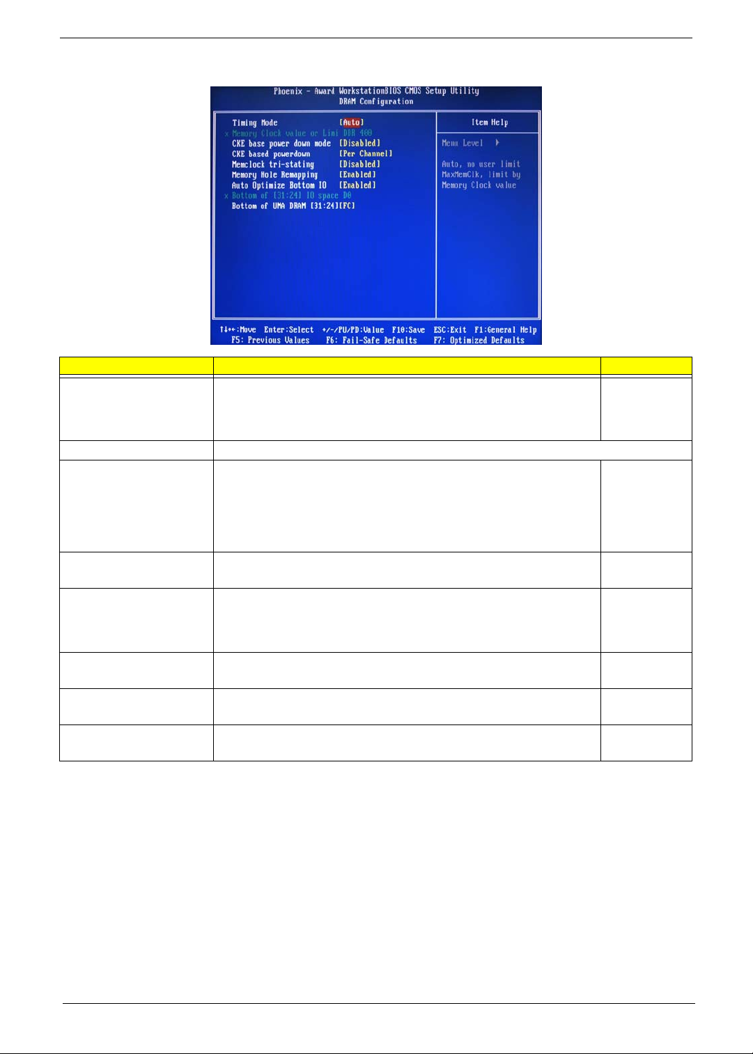
DRAM Configuration
Parameter Description Option
Timing Mode When set to auto mode, the system reads the electronic data sheet of the
Memory Clock value or Limit Displays the current memory clock frequency.
CKE base power down
mode
CKE based power down Sets the CKE power saving through disasserting clock enable using system
Memclock tri-stating Enables or disables the memory clock tri-stating during C3 an Alt VD
Memory Hole Remapping Enables or disables memory remapping around the memory hole. Enabled
Auto Optimize Bottom IO Allows you to auto optimize maximal memory size when kernel assigns PCI
Bottom of UMA DRAM
[31:24] [FC]
memory modules and adjusts the timings accordingly.
When set to MaxMemClk, you can manually specify the memory clock
frequency independent of the system bus frequency.
All synchronous memory devices can go into sleep mode as soon as the
clock enable (CKE) signal is disasserted. In that case, the internal clocks are
disabled and the memory chip goes into auto-refresh mode which is the
lowest power state at which the memory retains data.
If then power is turned off, the device will lose all data, however, as long as
standby power is maintained, no data loss will occur.
level or per channel basis.
feature.
Resources.
Allows you to enter a HEX number ranging from 0000 to 00F0. Minimim 0000
Auto
MaxMemClk
Disabled
Enabled
Per Channel
Per CS
Disabled
Memclock tristating during
C3 and Alt VD
Disabled
Enabled
Disabled
Maximum 00FC
Chapter 2 19
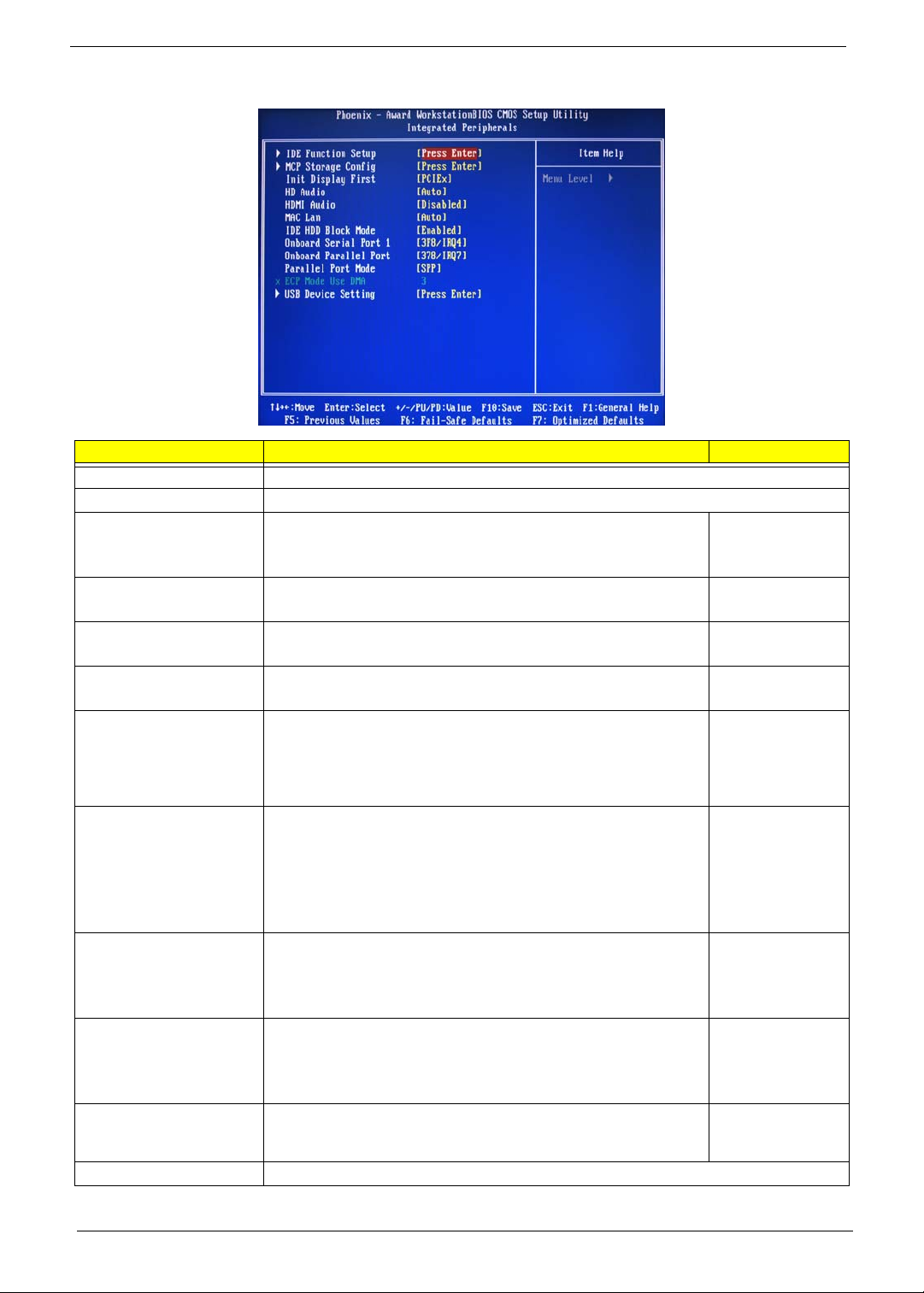
Integrated Peripherals
Parameter Description Option
IDE Function Setup Press Enter to access the IDE Function Setup submenu.
MCP Storage Config Press Enter to access the MCP Storage Config submenu.
Init Display First Select whether to boot the system using the AGP graphic card or a PCI
card installed on the PCI Express slot or PCI slot.
HD Audio Enables or disables the onboard audio controller. Auto
HDMI Audio Allows you to control the audio function of the onboard HDMI. Disabled
MAC LAN Enables or disables the built-in network interface card. Auto
IDE HDD Block Mode When enabled, the BIOS will automatically detect if your hard disk
supports block transfers and set the proper block transfer settings for it.
Depending on the IDE controller, up to 64 KB of data can be transferred
per interrupt when block transfers are enabled.
When disabled, only 512 bytes of data can be transferred per interrupt.
Onboard Serial Port 1 Select the I/O address and IRQ for the first serial port. 3F8/IRQ4
Onboard Parallel Port Select the I/O address and IRQ for the onboard parallel port. 378/IRQ7
Parallel Port Mode Select an operating mode for the onboard parallel port. SPP
ECPM Mode Use DMA Select DMA channel for the LPT port in ECP mode. This parameter can
be configured if the parallel port mode is set to ECP or ECP +EPP
mode.
USB Device Setting Press Enter to access the USB Device Setting submenu.
PCIEx
PCI Slot
Onboard
Disabled
Auto
Disabled
Enabled
Disabled
2F8/IRQ3
3E8/IRQ4
2E8/IRQ3
Auto
Disabled
278/IRQ5
3BC/IRQ7
Disabled
EPP
ECP
ECP+EPP
3
1
20 Chapter 2
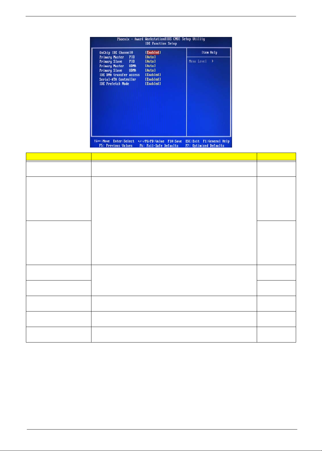
IDE Function Setup
Parameter Description Option
OnChip IDE Channel 0 Enables or disables the first IDE channel. Enabled
Disabled
Primary Master PIO
When set to Auto, BIOS setup automatically detects if the installed hard
disk supports the function. If supported, it allows for faster data recovery and
Primary Slave PIO Auto
Primary Master UDMA
Primary Slave UDMA Auto
IDE DMA Transfer Enables or disables DMA (Direct Memory Access) transfers for all IDE
Serial-ATA Controller Enables or disables the serial ATA controller. Enabled
IDE Prefetch Mode Enables or disables the IDE controller to prefetch data from the IDE drive. Enabled
read/write timing that reduces hard disk activity time. This results in better
hard disk performance. Mode 0 to 4 provide progressive increase of
performance.
Enables or disables the primary and master UDMA mode
drives.
Auto
Mode 0
Mode 1
Mode 2
Mode 3
Mode 4
Mode 0
Mode 1
Mode 2
Mode 3
Mode 4
Auto
Disabled
Disabled
Enabled
Disabled
Disabled
Disabled
Chapter 2 21
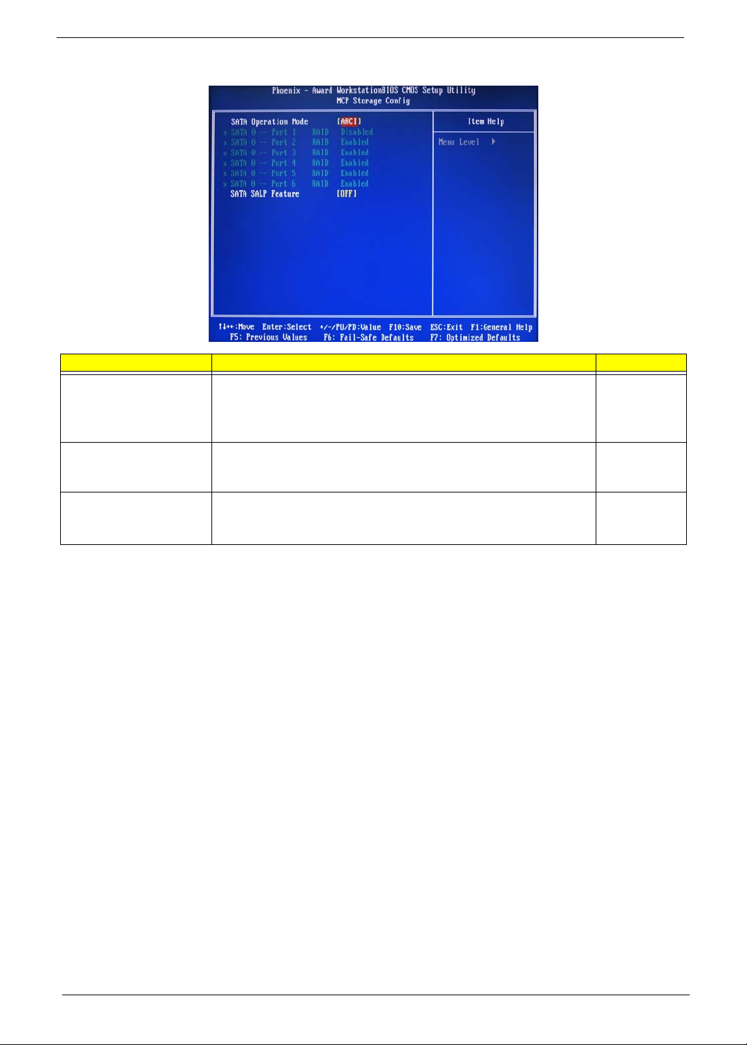
MCP Storage Config
Parameter Description Option
SATA Operation Mode Select a SATA operation mode. AHCI
IDE
RAID
Linux AHCI
SATA 0 -- Port 1 ~ 6 Enables or disables the SATA RAID on ports 1 to 6.
This parameter can be configured if the SATA Operation Mode is set to
RAID
SATA SALP Feature Select a Supports Aggressive Link Power Management (SALP) feature. Off
Disabled
Enabled
Partial
Slumber
22 Chapter 2

USB Device Setting
Parameter Description Option
USB 1.0 Controller
USB 2.0 Controller Enabled
USB Operation Mode Select a USB device operation speed. High Speed
USB Keyboard Function Enables or disables legacy support of the USB keyboard. Enabled
USB Mouse Function Enables or disables legacy support of the USB mouse. Enabled
USB Storage Function Enables or disables legacy support of the USB storage device. Enabled
Enables or disables the onboard USB controller.
Enabled
Disabled
Disabled
Full Low Speed
Disabled
Disabled
Disabled
Chapter 2 23
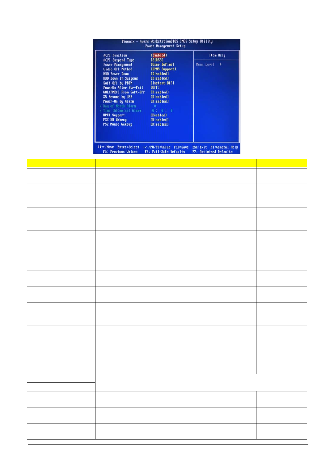
Power Management Setup
Parameter Description Option
ACPI function Enables or disables the Advanced Configuration and Power
ACPI Suspend Type Select an ACPI state. S1 & S3
Power Management Select a power saving method for the following modes:
Video Off Method Determines the manner when the monitor goes blank. DPMS Support
HDD Power Down Set a time when the hard disk drives will power down after a period
HDD Down in Suspend Enables or disables the HDD power down function in suspend mode. Disabled
Soft-Off by PBTN Determines the behavior of system power button. Instant-Off
PowerOn After Pwr-Fail Set the system to automatically start itself up after a power failure. Off
WOL (PME#)/From Soft-Off Enables or disables to wake up the system from a power saving mode
S5 Resume by USB If enabled, press any key or click the mouse will wake system from S1/
Power-On by Alarm Enables or disables to boot the system on scheduled date/time. Disabled
Day of Month Alarm
Time (hh:mm:ss) Alarm
HPET Support Enables or disables the High Precision Event Timer (HPET) function. Enabled
PS2 KB Wakeup Enables or disables to wake up the system from a power saving mode
PS2 Mouse Wakeup Enables or disables to wake up the system from a power saving mode
Management (ACPI) function.
• HDD power down
• Suspend mode
inactivity.
through an event on a LAN device or using soft-off.
S3 state.
This parameter can be configured if the Power-On by Alarm is set to enable.
using a PS2 keyboard.
using a PS2 mouse.
Enabled
Disabled
S1 (POS)
S3 (STR)
User Define
Min. Saving
Max Saving
Blank Screen
V/H Sync + Blank
Disabled
1 to 14 Min
Enabled
Delay 4 Sec
On
Former-Sts
Disabled
Enabled
Disabled
Enabled
Enabled
Disabled
Disabled
Enabled
Disabled
Enabled
24 Chapter 2

Power Management Setup (Eup)
Parameter Description Option
ACPI function Enables or disables the Advanced Configuration and Power
ACPI Suspend Type Select an ACPI state. S1 & S3
Power Management Select a power saving method for the following modes:
Video Off Method Determines the manner when the monitor goes blank. DPMS Support
HDD Power Down Set a time when the hard disk drives will power down after a period
HDD Down in Suspend Enables or disables the HDD power down function in suspend mode. Disabled
Soft-Off by PBTN Determines the behavior of system power button. Instant-Off
PowerOn After Pwr-Fail Set the system to automatically start itself up after a power failure. Off
WOL (PME#)/From Soft-Off Enables or disables to wake up the system from a power saving mode
S5 Resume by USB If enabled, press any key or click the mouse will wake system from S1/
Power-On by Alarm Enables or disables to boot the system on scheduled date/time. Disabled
Day of Month Alarm
Time (hh:mm:ss) Alarm
HPET Support Enables or disables the High Precision Event Timer (HPET) function. Enabled
PS2 KB Wakeup Enables or disables to wake up the system from a power saving mode
PS2 Mouse Wakeup Enables or disables to wake up the system from a power saving mode
Management (ACPI) function.
• HDD power down
• Suspend mode
inactivity.
through an event on a LAN device or using soft-off.
S3 state.
This parameter can be configured if the Power-On by Alarm is set to enable.
using a PS2 keyboard.
using a PS2 mouse.
Enabled
Disabled
S1 (POS)
S3 (STR)
User Define
Min. Saving
Max Saving
Blank Screen
V/H Sync + Blank
Disabled
1 to 14 Min
Enabled
Delay 4 Sec
On
Former-Sts
Disabled
Enabled
Disabled
Enabled
Enabled
Disabled
Disabled
Enabled
Disabled
Enabled
Chapter 2 25

PnP/PCI Configurations
Parameter Description Option
Reset Configuration Data If enabled, the system is forced to update Extended System
Configuration Data (ESCD) and then is automatically set to the
disabled mode.
If disabled, the system ESCD will update only when the new
configuration varies from the last one.
Resources Controlled By When set to auto ESCD, the system BIOS will detect the system
resources and automatically assign the relative IRQ and DMA channel
for each peripheral.
When set to manual, you have to assign the IRQ and DMA for add-on
cards.
IRQ Resources This parameter can be configured if the Resources Controlled By is set
to Manual.
It allows you to assign each system interrupt a type, depending on the
type of device using the interrupt.
PCI/VGA Palette Snoop Enables or disables the system graphic card to allow VGA palette
snooping.
Maximum Payload Size Set the maximum payload size for Transaction packets (TLP). 4096
Disabled
Enabled
Auto ESCD
Manual
IRQ-5
IRQ-7, IRQ-9,
IRQ-10, IRQ-11,
IRQ-14
Disabled
Enabled
128, 256, 512, 1024
2048
26 Chapter 2

PC Health Status
Parameter Description Option
Smart FAN Control Enables or disables the smart system fan control function. Enabled
Disabled
Shutdown Temperature Set the CPU shutdown temperature. Disabled
°°
60 C/140 F
°°
65 C/149 F
°°
70 C/158 F
Chapter 2 27
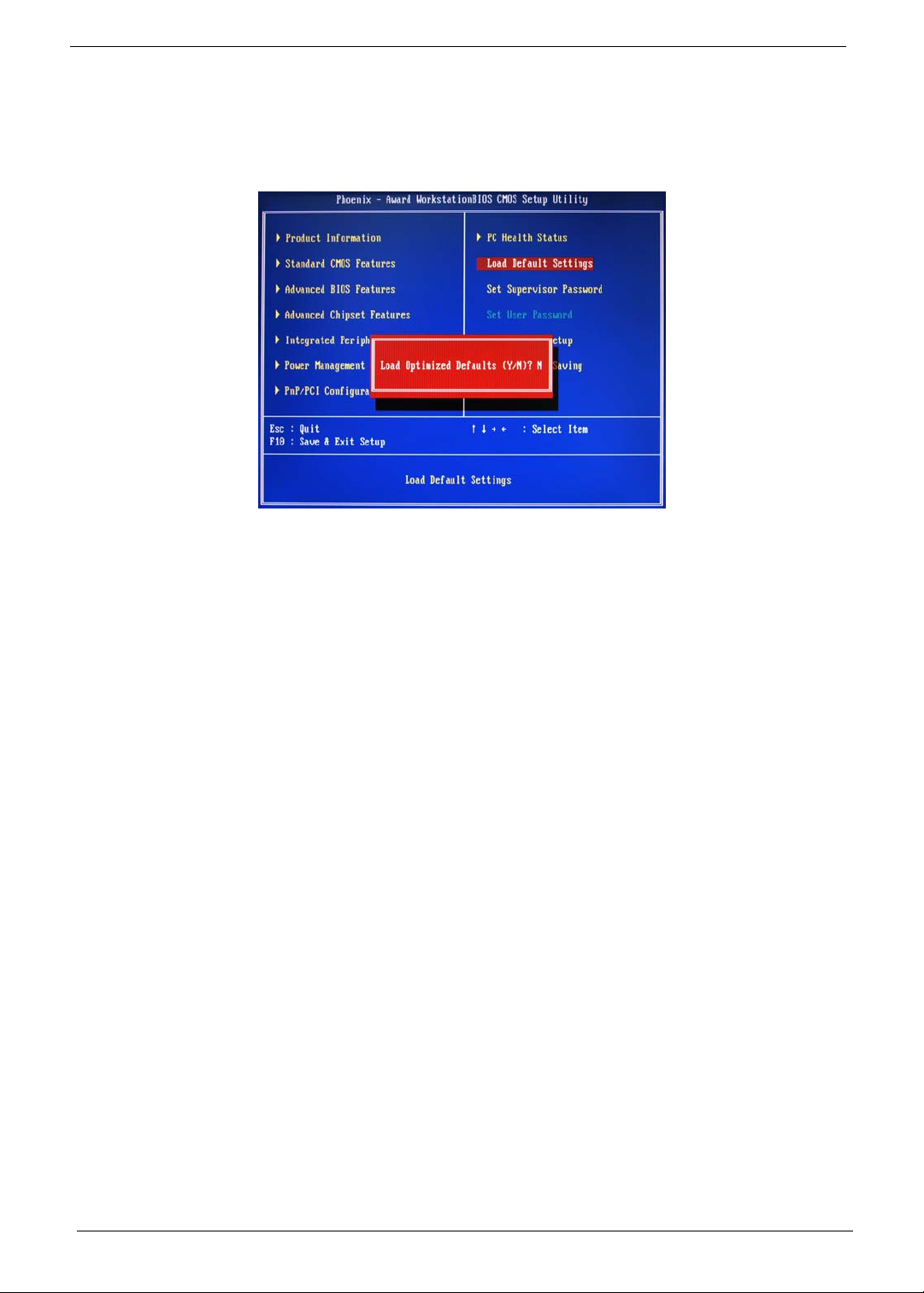
Load Default Settings
The Load Default Settings menu allows you to load the default settings for all BIOS setup parameters. Setup
defaults are quite demanding in terms of resources consumption. If you are using low-speed memory chips or
other kinds of low-performance components and you choose to load these settings, the system might not
function properly.
28 Chapter 2

Set Supervisor Password
The Set Supervisor Password menu allows you to set a supervisor password. The supervisor password allows
you to access and change all settings in the Setup Utility.
Setting a supervisor password
1. Use the up/down arrow keys to select Set Supervisor Password menu then press Enter.
A password box will appear.
2. Type a password then press Enter.
The password may consist up to six alphanumeric characters (A-Z, a-z, 0-9)
3. Retype the password to verify the first entry then press Enter again.
4. Press F10.
5. Select Yes to save the new password and close the Setup Utility.
Changing the supervisor password
1. Use the up/down arrow keys to select Set Supervisor Password menu then press Enter.
2. Type the original password then press Enter.
3. Type a new password then press Enter.
4. Retype the password to verify the first entry then press Enter again.
5. Press F10.
6. Select Yes to save the new password and close the Setup Utility.
Removing a supervisor password
1. Use the up/down arrow keys to select Set Supervisor Password menu then press Enter.
2. Enter the current password then press Enter.
3. Press Enter twice without entering anything in the password fields.
Chapter 2 29

Set User Password
The Set User Password menu allows you to set a user password. Entering this password will restrict a user’s
access to the Setup menus. A supervisor password must be set first before you can enable or disable this
field. A user can only access and modify the system time, system date, and set user password.
Setting a user password
1. Use the up/down arrow keys to select Set User Password menu then press Enter.
A password box will appear.
2. Type a password then press Enter.
The password may consist up to six alphanumeric characters (A-Z, a-z, 0-9)
3. Retype the password to verify the first entry then press Enter again.
4. Press F10.
5. Select Yes to save the new password and close the Setup Utility.
Changing the user password
1. Use the up/down arrow keys to select Set User Password menu then press Enter.
2. Type the original password then press Enter.
3. Type a new password then press Enter.
4. Retype the password to verify the first entry then press Enter again.
5. Press F10.
6. Select Yes to save the new password and close the Setup Utility.
Removing a user password
1. Use the up/down arrow keys to select Set User Password menu then press Enter.
2. Enter the current password then press Enter.
3. Press Enter twice without entering anything in the password fields.
30 Chapter 2
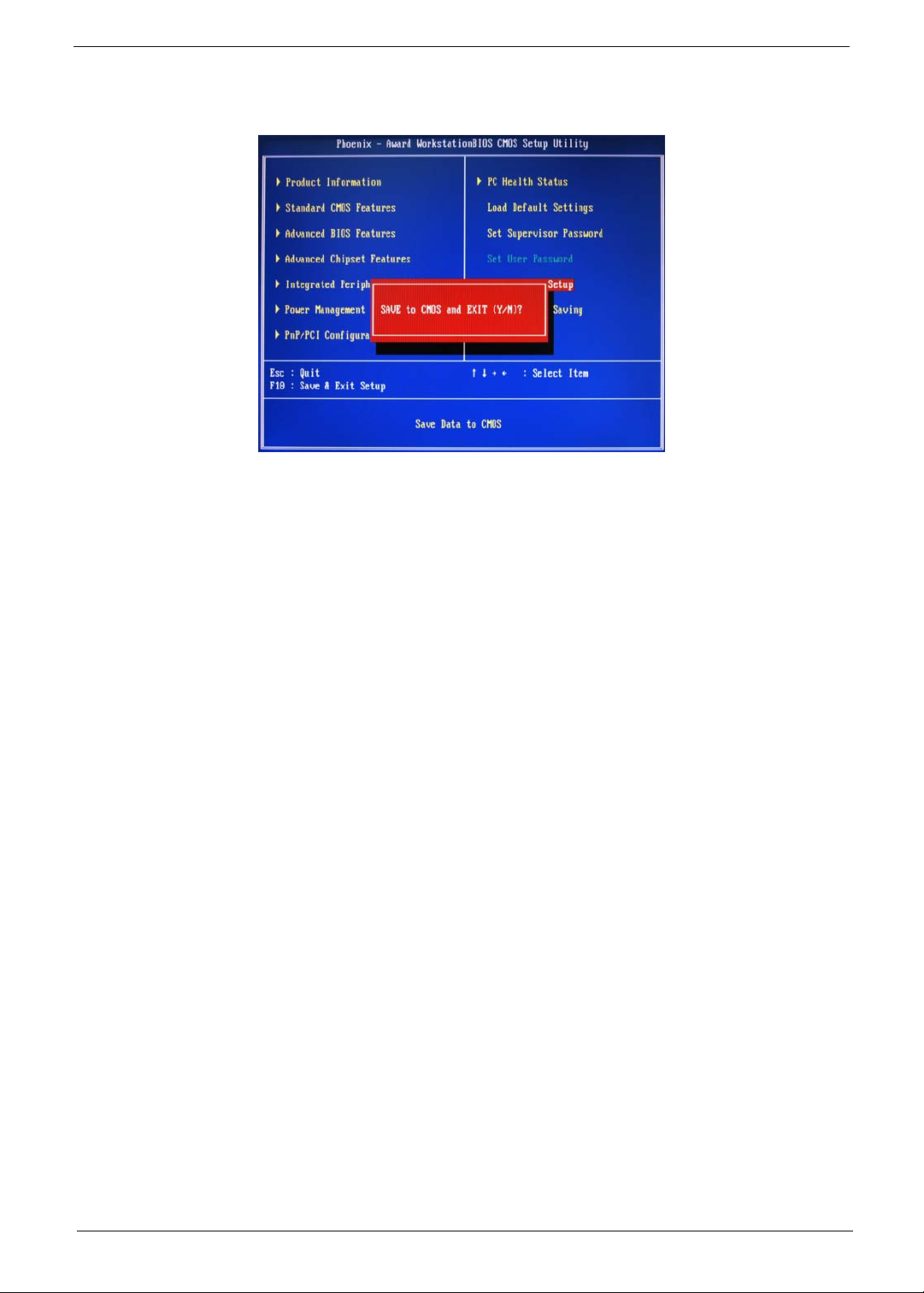
Save & Exit Setup
The Save & Exit Setup menu allows you to save changes made and close the Setup Utility.
Chapter 2 31

Exit Without Saving
The Exit Without Saving menu allows you to discard changes made and close the Setup Utility.
32 Chapter 2

Chapter 3
System Disassembly
This chapter contains step-by-step procedures on how to disassemble the desktop computer for maintenance
and troubleshooting.
Disassembly Requirements
To disassemble the computer, you need the following tools:
• Wrist grounding strap and conductive mat for preventing electrostatic discharge
• Flat-blade screwdriver
• Philips screwdriver
• Hex screwdriver
• Plastic flat-blade screwdriver
• Plastic tweezers
NOTE: The screws for the different components vary in size. During the disassembly process, group the
screws with the corresponding components to avoid mismatch when putting back the components.
Chapter 3 33

Pre-disassembly Procedure
Before proceeding with the disassembly procedure, perform the steps listed below:
1. Turn off the system and all the peripherals connected to it.
2. Unplug the power cord from the power outlets.
3. Unplug the power cord from the system.
4. Unplug all peripheral cables from the system.
5. Place the system unit on a flat, stable surface.
34 Chapter 3
Main Unit Disassembly
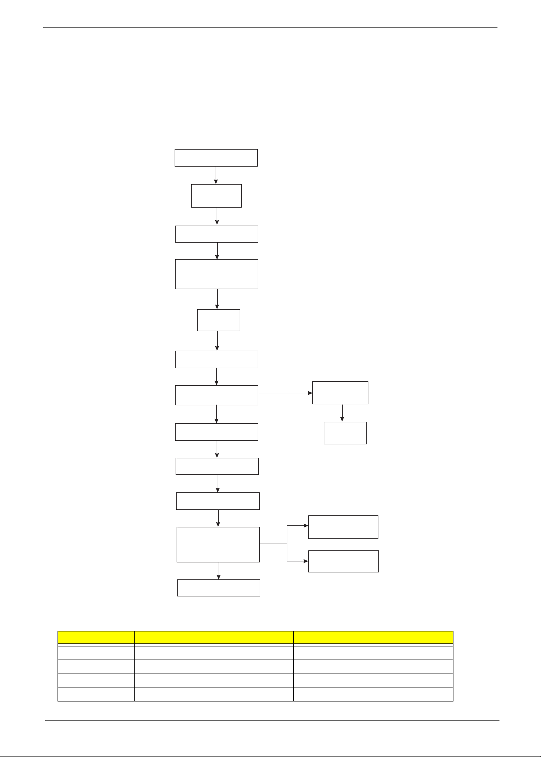
External Modules Disassembly Flowchart
The flowchart below gives you a graphic representation on the entire disassembly sequence and instructs you
on the components that need to be removed during servicing.
MAIN UNIT DISASSEMBLY
MAIN UNIT
Ax2
SIDE PANEL
FRONT BEZEL
HEAT SINK FAN
ASSEMBLY
CPU
Screw List
OPTICAL DISK DRIVE
Ax1
HDD-ODD BRACKET
Ax4
POWER SUPPLY
MEMORY MODULES
Ax1
PCI CARD
Bx2
FRONT I/O AND
CARD READER BOARD
BRACKET
Dx2
MAINBOARD
Ax6, Cx1
HDD MODULE
FRONT I/O BOARD
CARD READER
Bx1
HDD
Ax2
Ax2
BOARD
Screw Part No.
A #6-32 L5 BZN 86.00J07.B60
B #6-32*3/16 NI 86.5A5B6.012
C M3xL5 BZN 86.1A324.5R0
D Hex screw N/A
Chapter 3 35
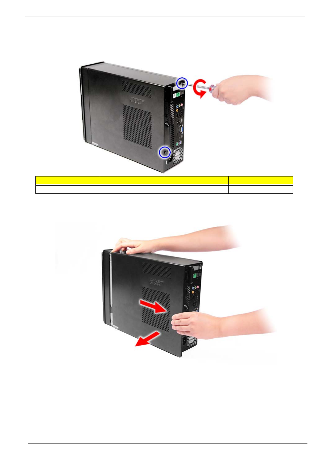
Removing the Side Panel
1. Perform the pre-disassembly procedure described on page 34.
2. Remove the screw (A) located on the rear edge of the side panel.
Screw (Quantity) Color Torq ue Part No.
#6-32 L5 BZN (2) Black 5.5 to 6.5 kgf-cm 86.00J07.B60
3. Slide the side panel toward the back of the chassis until the tabs on the cover disengage with the slots on
the chassis.
4. Lift the side panel away from the server and put it aside for reinstallation later.
36 Chapter 3

Removing the Font Bezel
1. Remove the side panel. Refer to the previous section for instructions.
2. Release the ffront bezel retention tab from the chassis interior.
3. Pull the bezel away from the chassis.
Chapter 3 37

Removing the Heat Sink Fan Assembly
WARNING:The heat sink becomes very hot when the system is on. NEVER touch the heat sink with any metal
or with your hands.
1. See “Removing the Side Panel” on page 36.
2. See “Removing the Font Bezel” on page 37.
3. Use a long-nosed screwdriver to loosen the four screws on the heat sink, in the order as shown below.
4. Lift the heat sink fan assembly away from the mainboard.
38 Chapter 3

5. Disconnect the fan cable from the mainboard.
6. Lay down the heat sink fan assembly in an upright position—with the thermal patch facing upward. Do not
let the thermal patch touch the work surface.
7. Use an alcohol pad to wipe off the thermal grease from both the heat sink and the processor socket
retention plate.
Chapter 3 39

Removing the Processor
IMPORTANT:Before removing a processor from the mainboard, make sure to create a backup file of all
important data.
WARNING:The processor becomes very hot when the system is on. Allow it to cool off first before handling.
1. See “Removing the Side Panel” on page 36.
2. See “Removing the Font Bezel” on page 37.
3. See “Removing the Heat Sink Fan Assembly” on page 38.
4. Release the load lever.
5. Pull the load lever to the fully open, upright position.
40 Chapter 3
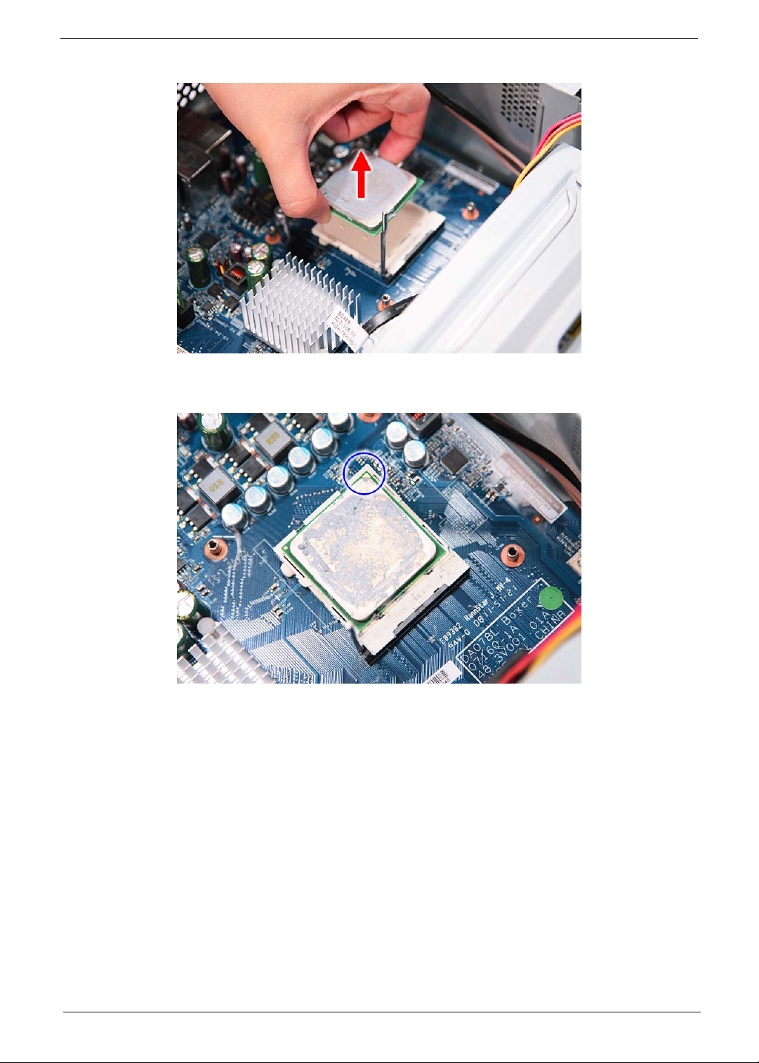
6. Pull out the processor from the socket.
IMPORTANT:If you are going to install a new processor, note the arrow on the corner to make sure the
processor is properly oriented over the socket.
Chapter 3 41
Removing the Optical Drive
1. See “Removing the Side Panel” on page 36.
2. See “Removing the Font Bezel” on page 37.
3. See “Removing the Heat Sink Fan Assembly” on page 38.
4. See “Removing the Processor” on page 40.
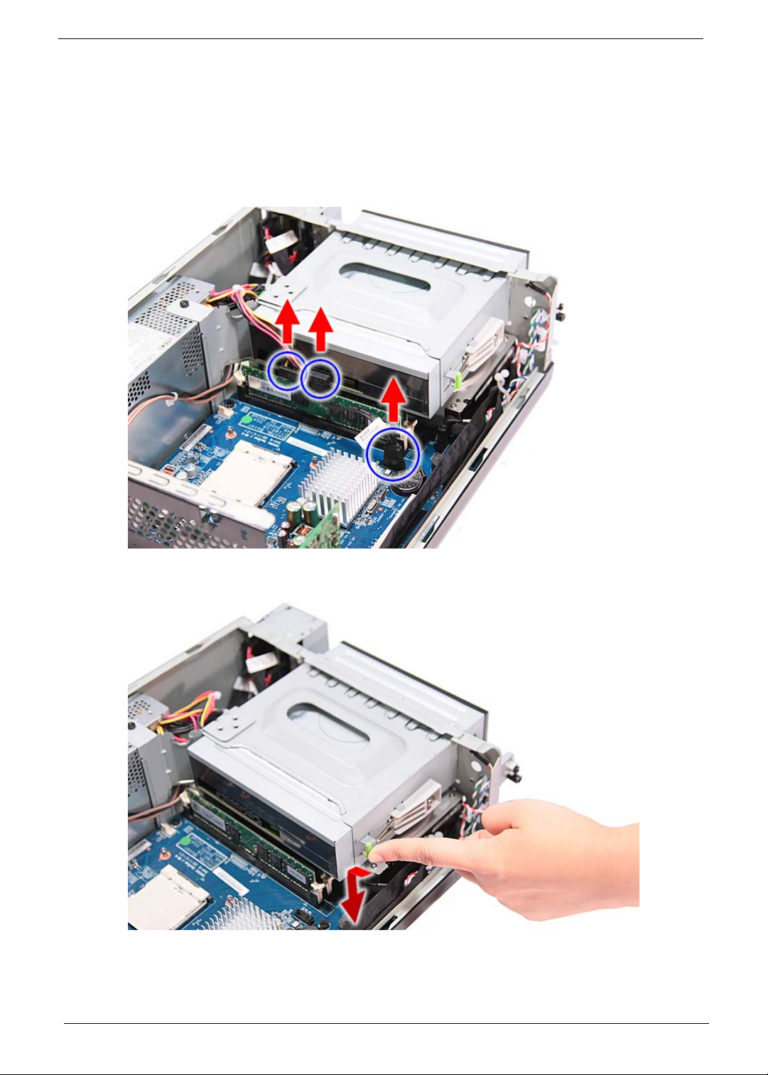
5. Disconnect the data and power cables from the rear of the optical drive and the mainboard.
6. Release the drive bay retention release lever.
42 Chapter 3

7. Pull the lever to the fully open position, as shown below.
8. Pull the drive out of the drive bay.
Chapter 3 43
Removing the Hard Disk Drive
1. See “Removing the Side Panel” on page 36.
2. See “Removing the Font Bezel” on page 37.
3. See “Removing the Heat Sink Fan Assembly” on page 38.
4. See “Removing the Processor” on page 40.
5. See “Removing the Optical Drive” on page 42.
6. Remove the HDD-ODD bracket.
a. Remove the screw (A) that secures the HDD bracket to the chassis.
Screw (Quantity) Color Torq ue Part No.
#6-32 L5 BZN (1) Black 5.5 to 6.5 kgf-cm 86.00J07.B60
44 Chapter 3

b. Lift the bracket out of the chassis.
7. Disconnect the data cable from the mainboard.
Chapter 3 45

8. Disconnect the data cable from the rear of the hard drive.
9. Disconnect the power cable from the rear of the hard drive.
10. Place the bracket on a clean, static-free work surface.
46 Chapter 3

11. Remove the HDD module.
a. Remove the four screws (B) that secures the HDD module to the HDD bracket.
Screw (Quantity) Color Torq ue Part No.
#6-32*3/16 NI (4) Silver 5.5 to 6.5 kgf-cm 86.5A5B6.012
b. Slide the HDD out of the bracket.
Chapter 3 47

Removing the Power Supply
1. See “Removing the Side Panel” on page 36.
2. See “Removing the Font Bezel” on page 37.
3. See “Removing the Heat Sink Fan Assembly” on page 38.
4. See “Removing the Processor” on page 40.
5. See “Removing the Optical Drive” on page 42.
6. See “Removing the Hard Disk Drive” on page 44.
7. Disconnect the 8-pin power supply cable from the mainboard.
8. Disconnect the 24-pin power supply cable from the mainboard.
48 Chapter 3

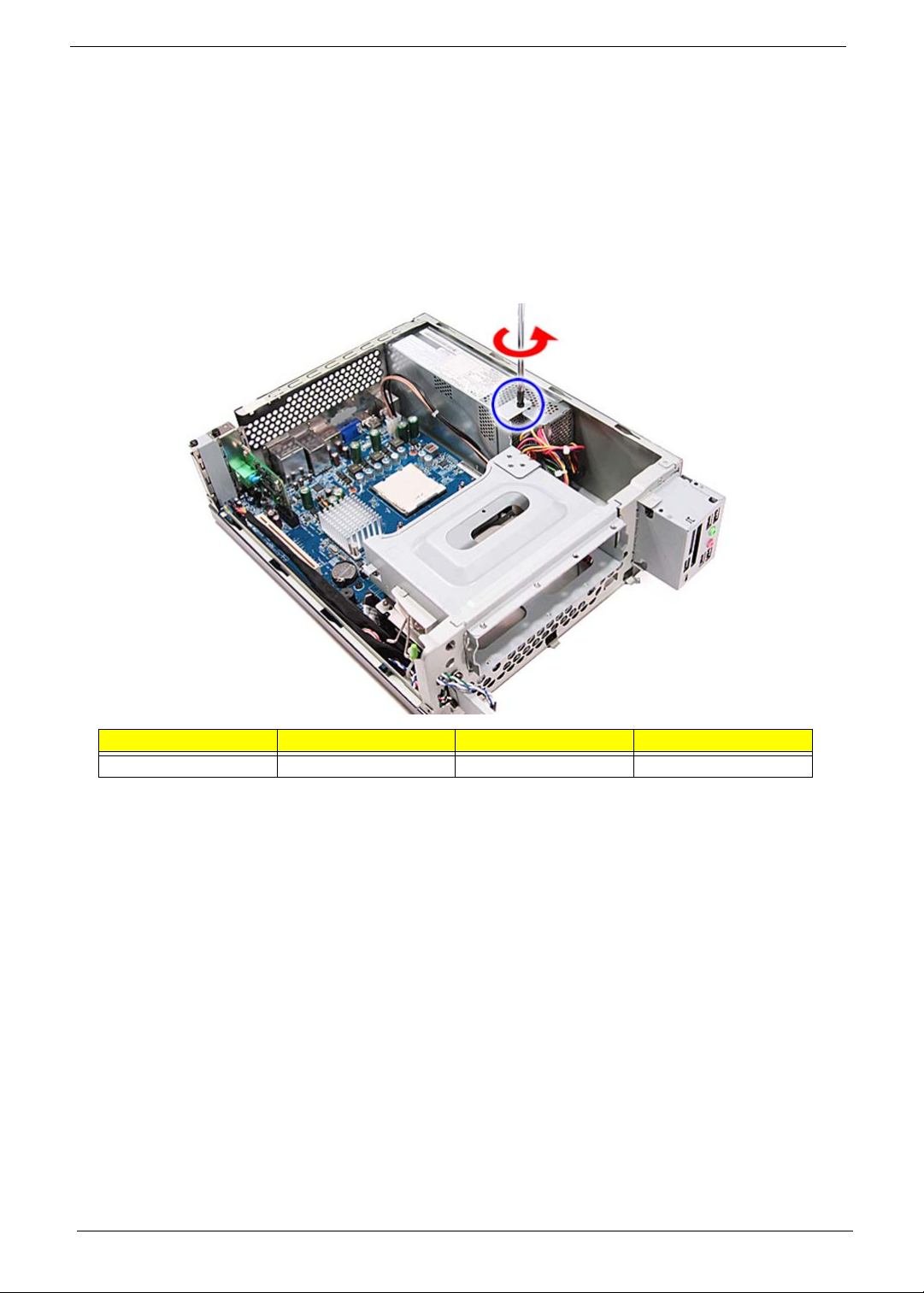
9. Remove the screw (A) that secures the power supply to the chassis.
Screw (Quantity) Color Torq ue Part No.
#6-32 L5 BZN (1) Black 5.5 to 6.5 kgf-cm 86.00J07.B60
10. Remove the three screws (A) that secure the power supply to the rear panel.
Screw (Quantity) Color Torq ue Part No.
#6-32 L5 BZN (3) Black 5.5 to 6.5 kgf-cm 86.00J07.B60
Chapter 3 49

11. Lift the power supply module out of the chassis.
50 Chapter 3
Removing the Memory Modules
IMPORTANT:Before removing any DIMM from the memory board, make sure to create a backup file of all
important data.
1. See “Removing the Side Panel” on page 36.
2. See “Removing the Font Bezel” on page 37.
3. See “Removing the Heat Sink Fan Assembly” on page 38.
4. See “Removing the Processor” on page 40.
5. See “Removing the Optical Drive” on page 42.
6. See “Removing the Hard Disk Drive” on page 44.
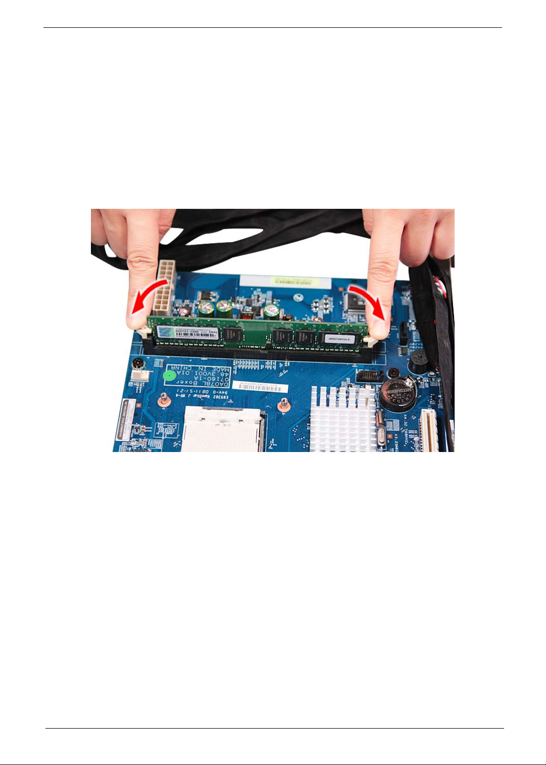
7. Press the holding clips on both sides of the DIMM slot outward to release the DIMM.
Chapter 3 51

8. Gently pull the DIMM upward to pull it away from the chassis.
52 Chapter 3

Removing the PCI Card
1. See “Removing the Side Panel” on page 36.
2. See “Removing the Font Bezel” on page 37.
3. See “Removing the Heat Sink Fan Assembly” on page 38.
4. See “Removing the Processor” on page 40.
5. See “Removing the Optical Drive” on page 42.
6. See “Removing the Hard Disk Drive” on page 44.
7. Remove the screw (A) that secures the card to the chassis.
Screw (Quantity) Color Torq ue Part No.
#6-32 L5 BZN (1) Black 5.5 to 6.5 kgf-cm 86.00J07.B60
Chapter 3 53

8. Gently pull the card to remove it from the mainboard.
54 Chapter 3

Removing the Front I/O and Card Reader Boards
1. See “Removing the Side Panel” on page 36.
2. See “Removing the Font Bezel” on page 37.
3. See “Removing the Heat Sink Fan Assembly” on page 38.
4. See “Removing the Processor” on page 40.
5. See “Removing the Optical Drive” on page 42.
6. See “Removing the Hard Disk Drive” on page 44.
7. See “Removing the Memory Modules” on page 51.
8. Disconnect one end of the three USB (1, 2, and 4), audio (2), and 1394 (5) cables from the rear of the I/O
and card reader boards.
Chapter 3 55

9. Disconnect the other end of the cables from the mainboard.
10. Remove the front I/O and card reader board bracket.
a. Remove the two screws (B) that secures the bracket to the chassis.
Screw (Quantity) Color Torq ue Part No.
#6-32*3/16 NI (2) Silver 5.5 to 6.5 kgf-cm 86.5A5B6.012
56 Chapter 3

b. Push the bracket inward, then remove the bracket from the chassis.
11. Remove the card reader board.
a. Remove the two screws (A) that secure the card reader board to the bracket.
Screw (Quantity) Color Torq ue Part No.
#6-32 L5 BZN (2) Black 5.5 to 6.5 kgf-cm 86.00J07.B60
Chapter 3 57

b. Pull the card reader board out of the bracket.
12. Remove the front I/O board.
a. Remove the two screws (A) that secure the I/O board to the bracket.
Screw (Quantity) Color Torq ue Part No.
#6-32 L5 BZN (2) Black 5.5 to 6.5 kgf-cm 86.00J07.B60
b. Pull the I/O board out of the bracket.
58 Chapter 3

Removing the Mainboard
1. See “Removing the Side Panel” on page 36.
2. See “Removing the Font Bezel” on page 37.
3. See “Removing the Heat Sink Fan Assembly” on page 38.
4. See “Removing the Processor” on page 40.
5. See “Removing the Optical Drive” on page 42.
6. See “Removing the Hard Disk Drive” on page 44.
7. See “Removing the Memory Modules” on page 51.
8. See “Removing the PCI Card” on page 53.
9. See “Removing the Front I/O and Card Reader Boards” on page 55.
10. Disconnect the LED cable from the mainboard.
11. Remove the three screws (C, D) from the rear panel.
Screw (Quantity) Color Torq ue Part No.
M3xL5 BZN (1) Black 5.5 to 6.5 kgf-cm 86.1A324.5R0
Hex screw (2) Silver N/A N/A
Chapter 3 59

12. Remove the six screws (A) that secures the mainboard to the chassis, in the order shown.
Screw (Quantity) Color Torq ue Part No.
#6-32 L5 BZN (6) Black 5.5 to 6.5 kgf-cm 86.00J07.B60
13. Lift the board from the chassis.
60 Chapter 3

Chapter 4
System Troubleshooting
This chapter provides instructions on how to troubleshoot system hardware problems.
Hardware Diagnostic Procedure
IMPORTANT:The diagnostic tests described in this chapter are only intended to test Acer products. Non-Acer
products, prototype cards, or modified options can give false errors and invalid system
responses.
1. Obtain the failing symptoms in as much detail as possible.
2. Verify the symptoms by attempting to recreate the failure by running the diagnostic tests or repeating the
same operation.
3. Refer to the table below to determine which corrective action to perform.
Problem Symptom Section to Refer to
Power failure The power indicator does not light up
or stay lit.
POST failure POST does not complete. No beep
or error codes issued.
POST detects an error and displayed
messages on screen.
“Power System Check” on page 62
“POST Error and Beep Codes” on page
63.
Chapter 4 61

System Check Procedures
Power System Check
If the system will power on, skip this section. Refer to System External Inspection.
If the system will not power on, do the following:
q Check if the power cable is properly connected to the system and AC source.
q Check if the voltage selector switch is set to the correct voltage setting.
System External Inspection
1. Inspect the LED indicators on the front panel, which can indicate the malfunction. For the LED locations
and description of their behaviour, see “System LED Indicators” on page 7.
2. Make sure that air flow is not blocked.
3. Make sure nothing in the system is making contact that could short out power.
4. If the problem is not evident, continue with System Internal Inspection.
System Internal Inspection
1. Turn off the system and all the peripherals connected to it.
2. Unplug the power cord from the power outlets.
3. Unplug the power cord from the system.
4. Unplug all peripheral cables from the system.
5. Place the system unit on a flat, stable surface.
6. Remove the system covers.
7. Verify that components are properly seated.
8. Verify that all cable connectors inside the system are firmly and correctly attached to their appropriate
connectors.
9. Verify that all components are Acer-qualified and supported.
10. Replace the system covers.
11. Power on the system.
12. If the problem with the system is not evident, you can try viewing the POST messages and BIOS event
logs during the system startup.
62 Chapter 4

POST Error and Beep Codes
NOTE: Perform the FRU replacement or actions in the sequence shown in FRU/Action column, if the FRU
replacement does not solve the problem, put the original part back in the computer. Do not replace a
non-defective FRU.
The error messages in the following table indicate the BIOS signals on the screen and the error symptoms
classified by functions. If the symptom is not included on the list, please refer to “Undetermined Problems”.
NOTE: Most of the error messages occur during POST. Some of them display information about a hardware
device, e.g., the amount of memory installed. Others may indicate a problem with a device, such as the
way it has been configured.
NOTE: If the system fails after you make changes in the BIOS Setup Utility menus, reset the computer, enter
Setup and install Setup defaults or correct the error.
POST Code (Hex) POST Routine Description
CFh Test CMOS R/W functionality
C0h Early chipset initialization
q Disable shadow RAM
q Disable L2 cache (socket 7 or below)
q Program basic chipset registers
C1h Detect memory
q Auto-detection of DRAM size, type, and ECC
q Auto-detection of L2 cache (socket 7 or below)
C3h Expand compressed BIOS code to DRAM
C5h Call chipset hook to copy BIOS back to E000 and F000 shadow RAM
01h Expand the X group codes locating in physical address 1000:0
02h Reserved
03h Initial Superio_Earl_Init switch
04h Reserved
05h 1 Blank out screen
2 Clear CMOS error flag
06h Reserved
07h 1 Clear 8042 interface
2 Initialize 8042 self-test
08h 1 Test special keyboard controller for Winbond 977 series Super I/O chips
2 Enabled keyboard interface
09h Reserved
0Ah 1 Disable PS/2 mouse interface (optional)
2 Auto detect ports for keyboard and mouse followed by a port and interface swap
(optional)
3 Reset keyboard for Winbond 977 series Super I/O chops
0Bh Reserved
0Ch Reserved
0Dh Reserved
0Eh Test F000h segment shadow to see whether it is rewritable or not. If test fails, keep
beeping the speaker.
0Fh Reserved
10h Auto detect flash type to load appropriate flash rewritable codes into the run time
area in F000 for ESCD & DMI support.
11h Reserved
Chapter 4 63

POST Code (Hex) POST Routine Description
12h Use walking 1’s algorithm to check out interface in CMOS circuitry. Also set real-
time clock power status, and then check for override.
13h Reserved
14h Program chipset default values into chipset. Chipset default values are
MODBINable by OEM customers.
15h Reserved
16h Initial onboard clock generator if Early_Init_Onboard_Generator is defined. See
also POST 26h.
17h Reserved
18h Detect CPU information including brand, SMI type (Cyrix or Intel) and CPU level
(586 or 686).
19h Reserved
1Ah Reserved
1Bh Initial interrupts vector table. If no special specified, all H/W interrupts are directed
to SPURIOUS_INT_HDLR & S/W interrupts to SPURIOUS_soft_HDLR.
1Ch Reserved
1Dh Initial EARLY_PM_INIT switch.
1Eh Reserved
1Fh Load keyboard matrix (notebook platform)
20h Reserved
21h HPM initialization (notebook platform)
22h Reserved
23h 1 Check validity of RTC value: e.g. a value of 5Ah is an invalid value for RTC
minute.
2 Load CMOS settings into BIOS stack. If CMOS checksum fails, use default value
instead.
24h Prepare BIOS resource map for PCI & PnP use. If ESCD is valid, take into
consideration of the ESCD’s legacy information.
25h Early PCI Initialization:
q Enumerate PCI bus number
q Assign memory & I/O resource
q Search for a valid VGA device & VGA BIOS, and put it into C000:0
26h 1 If Early_Init_Onboard_Generator is not defined Onboard clock generator
initialization. Disable respective clock resource to empty PCI & DIMM slots.
2 Init onboard PWM
3 Init onboard H/W monitor devices
27h Initialize INT 09 buffer
28h Reserved
29h 1 Program CPU internal MTRR (P6 & PII) for 0-640K memory address.
2 Initialize the APIC for Pentium class CPU. 3 Program early chipset according to CMOS setup. Example: onboard IDE
controller. Measure CPU speed.
2Ah Reserved
2Bh Invoke Video BIOS
2Ch Reserved
64 Chapter 4

POST Code (Hex) POST Routine Description
2Dh 1 Initialize double-byte language font (Optional)
2 Put information on screen display, including Award title, CPU type, CPU speed,
full screen logo.
2Eh Reserved
2Fh Reserved
30h Reserved
31h Reserved
32h Reserved
33h Reset keyboard if Early_Reset_KB is defined e.g. Winbond 977 series Super I/O
chips. See also POST 63h.
34h Reserved
35h Test DMA Channel 0
36h Reserved
37h Test DMA Channel 1
38h Reserved
39h Test DMA page registers
3Ah Reserved
3Bh Reserved
3Ch Test 8254
3Dh Reserved
3Eh Test 8259 interrupt mask bits for channel 1
3Fh Reserved
40h Test 8259 interrupt mask bits for channel 2
41h Reserved
42h Reserved
43h Test 8259 functionality
44h Reserved
45h Reserved
46h Reserved
47h Initialize EISA slot
48h Reserved
49h 1 Calculate total memory by testing the last double word of each 64K page.
2 Program write allocation for AMD K5 CPU.
4Ah Reserved
4Bh Reserved
4Ch Reserved
4Dh Reserved
4Eh 1 Program MTRR of M1 CPU
2 Initialize L2 cache for P6 class CPU & program CPU with proper cacheable
range
3 Initialize the APIC for P6 class CPU
4 On MP platform, adjust the cacheable range to smaller one in case the
cacheable ranges between each CPU are not identical
4Fh Reserved
50h Initialize the USB Keyboard & Mouse
Chapter 4 65

POST Code (Hex) POST Routine Description
51h Reserved
52h Test all memory (clear all extended memory to 0)
53h Clear password according to H/W jumper (Optional)
54h Reserved
55h Display number of processors (multi-processor platform)
56h Reserved
57h 1 Display PnP logo
2 Early ISA PnP initialization
q Assign CSN to every ISA PnP device
58h Reserved
59h Initialize the combined Trend Anti-Virus code
5Ah Reserved
5Bh (Optional Feature) Show message for entering AWDFLASH.EXE from FDD
5Ch Reserved
5Dh 1 Initialize Init_Onboard_Super_IO
2 Initialize Init_Onbaord_AUDIO
5Eh Reserved
5Fh Reserved
60h Okay to enter Setup utility; i.e. not until this POST stage can users enter the CMOS
setup utility.
6 h Reserved
6 h Reserved
6 h Reset keyboard if Early_Reset_KB is not defined
6 h Reserved
6 h Initialize PS/2 Mouse
6h Reserved
67h Prepare memory size information for function call: INT 15h ax=E820h
68h Reserved
69h Turn on L2 cache
6Ah Reserved
6Bh Program chipset registers according to items described in Setup & Auto-
configuration table.
6Ch Reserved
6Dh 1 Assign resources to all ISA PnP devices.
2 Auto assign ports to onboard COM ports if the corresponding item in Setup is set
to “AUTO”.
6Eh Reserved
6Fh 1 Initialize floppy controller
2 Set up floppy related fields in 40:hardware
70h Reserved
71h Reserved
72h Reserved
73h Reserved
74h Reserved
75h Detect & install all IDE devices: HDD, LS120, ZIP, CDROM…..
66 Chapter 4
POST Code (Hex) POST Routine Description
76h (Optional Feature) Enter AWDFLASH.EXE if: -AWDFLASH.EXE is found in floppy
drive. -ALT+F2 is pressed.
77h Detect serial ports & parallel ports
78h Reserved
79h Reserved
7Ah Detect & install co-processor
7Bh Reserved
7Ch Init HDD write protect
7Dh Reserved
7Eh Reserved
7Fh Switch back to text mode if full screen logo is supported.
q If errors occur, report errors & wait for keys
q If no errors occur or F1 key is pressed to continue:
q Clear EPA or customization logo
80h Reserved
81h Reserved
E8POST.ASM starts
82h 1 Call chipset power management hook
2 Recover the text fond used by EPA logo (not for full screen logo) 3 If password is set, ask for password
83h Save all data in stack back to CMOS
84h Initialize ISA PnP boot devices
85h 1 USB final Initialization
2 Switch screen back to text mode
86h Reserved
87h NET PC: Build SYSID Structure
88h Reserved
89h 1 Assign IRQs to PCI devices
2 Set up ACPI table at top of the memory
8Ah Reserved
8Bh 1 Invoke all ISA adapter ROMs
2 Invoke all PCI ROMs (except VGA)
8Ch Reserved
8Dh 1 Enable/Disable Parity Check according to CMOS setup
2 APM Initialization
8Eh Reserved
8Fh Clear noise of IRQs
90h Reserved
91h Reserved
92h Reserved
93h Read HDD boot sector information for Trend Anti-Virus code
Chapter 4 67

POST Code (Hex) POST Routine Description
94h 1 Enable L2 cache
2 Program Daylight Saving 3 Program boot up speed 4 Chipset final initialization 5 Power management final initialization 6 Clear screen & display summary table 7 Program K6 write allocation 8 Program P6 class write combining
95h Update keyboard LED & typematic rate
96h 1 Build MP table
2 Build & update ESCD 3 Set CMOS century to 20h or 19h 4 Load CMOS time into DOS timer tick 5 Build MSIRQ routing table
FFh Boot attempt (INT 19h)
68 Chapter 4

Online Support Information
This section describes online technical support services available to help you repair the desktop computer.
If you are a distributor, dealer, ASP or TPM, please refer your technical queries to your local Acer branch
office. Acer Branch Offices and Regional Business Units may access our website at http://global.acer.com/
support/index. However some information sources will require a user ID and password. These can be obtained
directly from Acer CSD Taiwan.
Acer's Website offers you convenient and valuable support resources whenever you need them.
In the Support & Downloads tab you can download information materials for all of Acer notebook, desktop and
server models including:
q Service guides for all models
q User's manuals
q Training materials
q BIOS updates
q Software utilities
q Spare parts lists
q Technical Announcement Bulletins (TABs)
For these purposes, we have included an Acrobat File to facilitate a hassle-free downloading of our technical
materials.
The following are also available in the Support & Downloads tab:
q Detailed information on Acer's International Traveler's Warranty (ITW)
q Returned material authorization procedures
q An overview of all the support services we offer, accompanied by a list of telephone, fax, and email
contacts for all your technical queries.
We are always looking for ways to optimize and improve our services, so if you have any suggestions or
comments, please do not hesitate to communicate these to us.
Chapter 4 69

70 Chapter 4
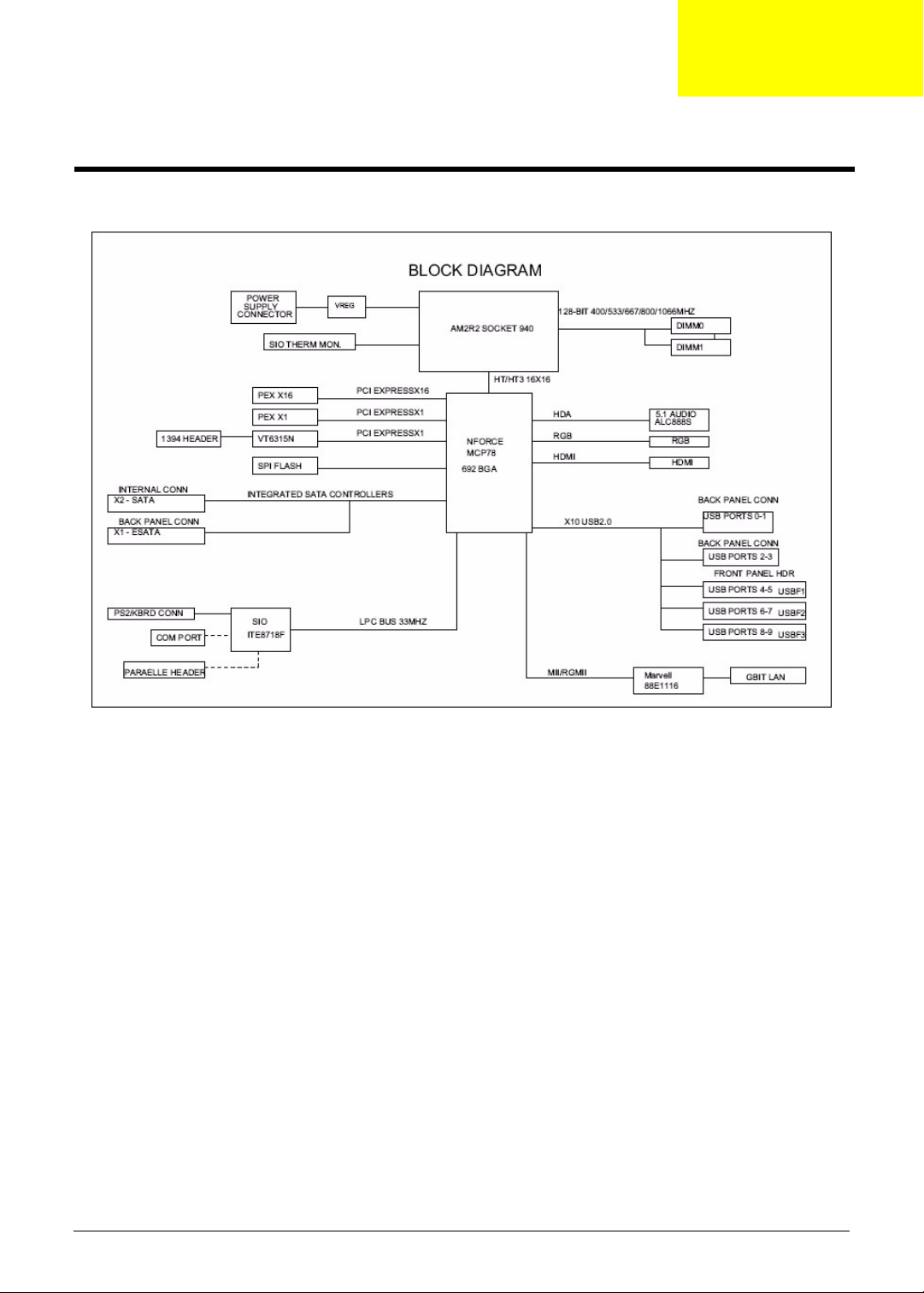
System Block Diagram and Board Layout
System Block Diagram
Chapter 5
Chapter 5 71

Board Layout
Mainboard
No Code Description No Code Description
1 CPUFAN1 Processor fan cable connector 13 JBIOS1 Clear CMOS jumper
2 PWR2 24-pin ATX power connector 14 FIREH1 IEEE 1394 connector
3 DIMM1 and 2 System memory slots 15 AUDIOF1 Front audio connector
4 UI Processor socket 16 PCIEX16 PCI Express x16 slot
5 DEBUGH1 Debug connector 17 PCIEX1 PCI Express x1 slot
6 SATA2 SATA 2 data cable connector 18 Top: Line-out and line-in jack
and rear speaker and center
speaker jack
Bottom: Microphone port and
S/PDIF port
7 LEDH1 LED cable connector 19 Top: Gigabit LAN port
Bottom: USB ports
8 SYSFAN1 System fan cable connector 20 Top: USB ports
Bottom: eSATA port
9 USBF3 Front USB connectors 21 VGA port
10 USBF2 22 HDMI port
11 SATA1 SATA 1 data cable connector 23 Top: PS2 Mouse Port
Bottom: PS2 Keyboard Port
12 USBF1 Front USB connector 24 PWR1 8-pin ATX power connector
72 Chapter 5

System Jumpers
Name Location Default Settings
Clear CMOS/NVRAM JBIOS1 1-2
SKU selection GPIOH1 1-2
2-3
2-3
Normal (default)
Clear CMOS
SSID = 0153 AX1200
SSID = 0157 AX3200
Chapter 5 73

74 Chapter 5

Chapter 6
FRU (Field Replaceable Unit) List
This chapter offers the FRU (Field Replaceable Unit) list in global configuration of the Aspire X1300/X1301
desktop computer. Refer to this chapter whenever ordering the parts to repair or for RMA (Return Merchandise
Authorization).
NOTES:
• When ordering FRU parts, check the most up-to-date information available on your regional web
or channel. For whatever reasons a part number is changed, it will NOT be noted on the printed
Service Guide. For Acer authorized service providers, your Acer office may have a different part
number code from those given in the FRU list of this printed Service Guide. You MUST use the
local FRU list provided by your regional Acer office to order FRU parts for service.
• To scrap or to return the defective parts, follow the local government ordinance or regulations on
how to dispose it properly, or follow the rules set by your regional Acer office on how to return it.
• This document will be updated as more information about the FRU list becomes available.
Chapter 6 75

Aspire X1300/X1301 Exploded Diagram
76 Chapter 6

Aspire X1300/X1301 FRU List
Component QTY Part Name Description
Board
Front I/O board 1 FRONT I/O BOARD DA078L/BOXER FRONT I/O BD
MRP
Card reader board 1 CARD READER BOARD DA078L/BOXER CARD READER
MRP
Modem card 1 MODEM CARD LITE-ON D-
1156E#A10A LOW-PROFILE PCI-E
56K V.92
TV tuner card 1 TV TUNNER CARD YUAN
VGA card 1 VGA CARD PC PARTNER
Cable
Card reader (1394) 1 CARD READER CABLE C.A. 1394 BOXER VSO 50.SAR01.001
USB board cable 1 USB BOARD CABLE C.A. USB BOXER VSO 50.SAR01.002
Audio board cable 1 AUDIO BOARD CABLE C.A. AUDIO BOXER VSO 50.SAR01.003
SATA ODD cable 1 SATA ODD CABLE (SHORT) C.A. SATA ODD BOXER VSO 50.SAR01.004
SATA HDD - MB 1 SATA HDD CABLE (LONG) C.A. SATA HDD BOXER VSO 50.SAR01.005
Power board and
LED board cable
Case/Cover/Bracket Assembly
Front bezel 1 FRONT BEZEL WITH NAME PLATE ASSY FRONT-BEZEL-ASM
Upper case 1 UPPER CASE ASSY DOOR BOXER95 60.SAR01.002
Chassis with
power and LED
cable
I/O dummy cover
bracket
I/O holder 1 IO HOLDER SHIELDING REAR IO BOXER95 33.SAR01.002
HDD and ODD
cover bracket
CPU
Athlon 64 X2, 65W 1 CPU AMD 2.5G ADO4850IAA5DO
PE585QA PCI-E HYBRID S/W
MPEG (ATSC+NTSC) W/LP BRKT
1 TV TUNNER CARD HAUPPAUGE
HVR-1200 PCIE HYBRID DVB-T S/
W ENCORDER W/LP BRKT
GEFORCE 8400 256MB DDRII
VGA+TVO+DVI PAL W/LP BRK LF
1 VGA CARD PC PARTNER
GEFORCE 8400 256MB DDRII
VGA+TVO+DVI NTSC W/LP BRK LF
2 POWER BOARD&LED BOARD
CABLE
1 CHASSIS WITH POWER & LED
CABLE
1 IO DUMMY COVER BRACKET BRKT F-IO BOXER95 33.SAR01.001
1 HDD&ODD COVER BRACKET ASSY BRKT-ODD-HDD 33.SAR01.003
ATH LON
1 CPU AMD 2.2G ADO4200IAA5DO
ATHLON64*2
1 CPU AMD 2.3G ADO4400IAA5DO
ATHLON64*2
MODEM 56K ATX LSI UNIVERSAL (PFX.10100.003
TV TUNER CARD PE585QA PCI-E HYTU.10500.010
HAUPPAGUE WIN-TV HVR-1200
PCIE
VGA CARD GEFORCE 8400 256MB VG.PC84L.013
VGA CARD GEFORCE 8400 256MB VG.PC84L.014
C.A. LED-SWITCH BOXER VSO 50.SAR01.006
BOXER95
ASSY MAIN-CHASSIS BOXER95 60.SAR01.003
IC CPU ATHLON 4850E 2.5G G2 KC.AE002.485
IC CPU ATHLON64*2 4200+ 2.2G KC.A4202.X2Z
IC CPU ATHLON64*2 4400+ 2.3G KC.A4402.X2Z
Acer
Part Number
55.SAR01.001
55.SAR01.002
TU.10500.011
60.SAR01.001
Chapter 6 77

Component QTY Part Name Description
Athlon 64 X2, 65W 1 CPU AMD 2.4G ADO4600IAA5DO
ATHLON64*2
1 CPU AMD 2.5G G2
ADO4800IAA5DO ATHLON64*2
1 CPU AMD 2.6G ADO5000IAA5DO
ATHLON64*2
1 CPU AMD 2.7G G2
ADO5200IAA5DO ATHLON64*2
1 CPU AMD 2.8G ADO5600IAA5DO
ATHLON64*2
Athlon X2, 45W 1 CPU AMD 2.9G ADH2300IAA5DO
ATHLON64*2
1 CPU AMD 2.1G ADH2350IAA5DO
ATHLON64*2
1 CPU AMD 2.3G ADH2400IAA5DO
ATHLON64*2
Athlon, 45W 1 CPU AMD 2.7G G2
ADH1640IAA4DP ATHLON LE-1640
1 CPU AMD 2.8G G2
ADH1660IAA4DP ATHLON LE-1660
1 CPU AMD 2.2G ADA4000IAA4DH
ATHLON LE-1600
1 CPU AMD 2.4G ADH1620IAA5DH
ATHLON LE-1620
Phenom,Quad
Core, 65W
Phenom,Triple
Core, 89W
Phenom,Quad
Core, 95W
1 CPU AMD 1.8G HD91000BJ4BGD
PHENOM 9100E
1 CPU AMD 1.8G HD91500BJ4BGD
PHENOM 9150E
1 CPU AMD 2.1G HD8400WCJ3BGD
PHENOM 8400
1 CPU AMD 2.1G HD8450WCJ3BGD
PHENOM 8450
1 CPU AMD 2.3G HD8600WCJ3BGD
PHENOM 8600
1 CPU AMD 2.3G HD8650WCJ3BGD
PHENOM 8650
1 CPU AMD 2.5G HD8700WCJ3BGD
PHENOM 8700
1 CPU AMD 2.4G HD8750WCJ3BGD
PHENOM 8750
1 CPU AMD 2.2G HD9500WCJ4BGD
PHENOM 9500
1 CPU AMD 2.2G HD9550WCJ4BGD
PHENOM 9550
1 CPU AMD 2.4G HD9600WCJ4BGD
PHENOM 9600
1 CPU AMD 2.3G HD9650WCJ4BGD
PHENOM 9650
1 CPU AMD 2.4G HD9750WCJ4BGD
PHENOM 9750
IC CPU ATHLON64*2 4600+ 2.4G KC.A4602.X2Z
IC CPU ATHLON64*2 4800+ G2 KC.A4802.X2Z
IC CPU ATHLON64*2 5000+ 2.6G KC.A5002.X2Z
IC CPU ATHLON64*2 5200+ G2 KC.A5202.X2Z
IC CPU ATHLON64*2 5600+ 2.8G KC.A5602.X2Z
IC CPU ATHLON64*2 BE-2300 1.9G KC.ABZ02.230
IC CPU ATHLON64*2 BE-2350 2.1G KC.ABZ02.235
IC CPU ATHLON64*2 BE-2400 2.3G KC.ABZ02.240
IC CPU ATHLON LE-1640 2.7G G2 KC.ALE02.164
IC CPU ATHLON LE-1660 2.8G G2 KC.ALE02.166
IC CPU ATHLON LE-1600 2.2G KC.ALF02.160
IC CPU ATHLON LE-1620 2.4G KC.ALF02.162
IC CPU PHENOM 9100E 1.8G KC.PHE02.910
IC CPU PHENOM 9150E 1.8G KC.PHE02.915
IC CPU PHENOM 8400 2.1G KC.PHN02.840
IC CPU PHENOM 8450 2.1G KC.PHN02.845
IC CPU PHENOM 8600 2.3G KC.PHN02.860
IC CPU PHENOM 8650 2.3G KC.PHN02.865
IC CPU PHENOM 8700 2.5G KC.PHN02.870
IC CPU PHENOM 8750 2.4G KC.PHN02.875
IC CPU PHENOM 9500 2.2G KC.PHN02.950
IC CPU PHENOM 9550 2.2G KC.PHN02.955
IC CPU PHENOM 9600 2.4G KC.PHN02.960
IC CPU PHENOM 9650 2.3G KC.PHN02.965
IC CPU PHENOM 9750 2.4G KC.PHU02.975
Acer
Part Number
78 Chapter 6
Component QTY Part Name Description
Sempron, 45W 1 CPU AMD 2.2G SDH1250IAA4DP
SEMPRON LE-1250
1 CPU AMD 2.5G G2
SDH1300IAA4DP SEMPRON LE1300
Optical drive
DVD-RW drive 1 DVD-RW DRIVE BD 4X HLDS
GGW-H20N LF BLACK BEZEL
SATA
1 DVD-RW DRIVE SUPER MULTI 16X
PHILIPS DH-16A3S LF BLACK
BEZEL SATA
1 DVD-RW DRIVE SUPER MULTI 16X
HLDS GH15N LF BLACK BEZEL
SATA
1 DVD-RW DRIVE SUPER MULTI 16X
SONY AD-7170S LF SATA
1 DVD-RW DRIVE BD 4X HLDS GGC-
H20N LF BALCK BEZEL SATA
1 DVD-ROM DRIVE 16X PHIPLIS DH-
16D2S LF W/O BEZEL SATA
1 DVD-ROM DRIVE 16X HLDS GDR-
H20N LF BALCK BEZEL SATA
Hard disk drive
160 GB 1 HDD 160GB 3.5" 7200RPM SATA II
HGST HDS721616PLA380 LF F/
W:BEA
1 HDD 160GB 3.5" 7200RPM SATA II
SEAGATE ST3160815AS LF F/
W:3.AAE
250 GB 1 HDD 250GB SEAGATE
ST3250310AS
1 HDD 250GB 3.5" 7200RPM SATA II
HGST HDP725025GLA380 LF F/
W:52A
320 GB 1 HDD 320GB 3.5" 7200RPM SATA II
SEAGATE ST3320820AS LF F/
W:3.AAD
1 HDD 320GB SATA HGST
HDP725032GLA380
1 HDD 320GB 3.5" 7200RPM SATA
WD WD3200AAJS-22VWA0 LF F/
W:12.01B02
500 GB 1 HDD 500GB 3.5" 7200RPM SATA II
SEAGATE ST3500830AS LF F/
W:3AAD
1 HDD 500GB 3.5" 7200RPM SATA II
HGST HDP725050GLA380 LF F/
W:52A
1 HDD 500G 3.5" 7200RPM SATA II
WD WD5000AAJS-22YFAO LF F/
W:12.01C02
1 HDD 500GB 3.5" 7200RPM SATA II
WD WD5000AAJS-22A8B0 LF F/
W:01.03A01
IC CPU SEMPRON LE-1250 2.2G KC.SLE02.125
IC CPU SEMPRON LE-1300 2.5G G2KC.SLE02.130
BD-R HLDS GGW-H20N BOXER KU.0040D.012
SUPER MULTI SATA DH-16A3S
BOXE
SUPER MULTI SATA GH-15N
BOXER
S-MUL SATA SONY/AD-7170S
OSCAR
BD 4X HLDS GGC-H20N BOXER KV.0040D.001
DVDROM SATA PLDS/DH-16D2S
OSCA
DVDROM SATA HLDS/GDR-H20N
PERS
HGST 160GB SATA 8MB 7200 NCQ KH.16007.017
HDD 160GB SGT ST3160815AS KH.16001.030
HDD 250GB SEAGATE
ST3250310AS
HDD 250GB HGST
HDP725025GLA380
HDD SEAGATE 320GB
ST3320820AS
HDD 320GB HGST
HDP725032GLA380
HDD 320GB WD WD3200AAJS22VWA0
HDD 500GB SGT SATA
ST3500830AS
HDD 500GB HGST
HDP725050GLA380
HDD 500GB WD WD5000AAJS22YFAO
HDD 500GB WD5000AAJS-22A8B0 KH.50008.009
Acer
Part Number
KU.01609.005
KU.0160D.034
KU.0160E.001
KV.01609.003
KV.0160D.014
KH.25001.010
KH.25007.012
KH.32001.007
KH.32007.003
KH.32008.012
KH.50001.004
KH.50007.003
KH.50008.005
Chapter 6 79

Component QTY Part Name Description
640 GB 1 HDD 640GB 3.5" 7200RPM SATA II
WD WD6400AAKS-22A7B0 LF F/
W:01.03B01
750 GB 1 HDD 750GB 3.5" 7200RPM SATA II
SEAGATE ST3750840AS LF F/
W:3.AAD
1 HDD 750GB 3.5" 7200RPM SATA II
HGST HDS721075KLA330 LF F/
W:70M
1 HDD 750GB 3.5" 7200RPM SATA II
WD WD7500AAKS-22RBA0 LF F/
W:30.04G30
1 TB 1 HDD 1000GB 3.5" 7200RPM SATA II
HGST HDS721010KLA330 LF F/
W:70M
Heat sink
1 CPU COOLER WITH FAN LGA775
TMDC6 (TMD06 W/O FAN DUCT)
Keyboard
1 KEYBOARD PS2 104KEY
CHICONY KB-07593US2552V
US2552V US BLAC
1 KEYBOARD PS2 104KEY
CHICONY KB-07593RD2552V
TRADITIONAL CHINESE BLACK
1 KEYBOARD PS2 104KEY
CHICONY KB-07593RE2552V
SIMPLE CHINESE BLACK
1 KEYBOARD PS2 104KEY
CHICONY KB-07593U42552V US-I
BLACK
1 KEYBOARD PS2 104KEY
CHICONY KB-07593A02552V
ARABIC/ENGLISH
1 KEYBOARD PS2 104KEY
CHICONY KB-07593T02552V THAI
BLACK
1 KEYBOARD PS2 105KEY
CHICONY KB-07596E02552V
SPANISH BLACK
1 KEYBOARD PS2 105KEY
CHICONY KB-07596P02552V
PORTUGUESE BLACK
1 KEYBOARD PS2 105KEY
CHICONY KB-07596CA2552V
CANADA/FRENCH
1 KEYBOARD PS2 107KEY
CHICONY KB-07598PA2552V
BRAZILIAN PORTU
1 KEYBOARD PS2 109KEY
CHICONY KB-07590J02552V
JAPANESE BLACK
1 KEYBOARD PS2 105KEY
CHICONY KB-07596D12552V
GERMAN BLACK
HDD 640GB WD WD6400AAKS22A7B0
SEAGATE 750G SATA 8MB 7200
NCQ
HGST 750GB SATA 8MB 7200 NCQ KH.75007.001
HDD WD 750GB SATA 8MB 7200
NCQ
HDD HGST 1TB SATA 8MB 7200
NCQ
ASSY COOLER LGA775 ATX HI.10800.012
KB PS2 KB-07593US2552V US
BLAC
KB PS2 KB-0759 T-CN BLACK 104K KB.PS203.097
KB PS2 KB-0759 S-CN BLACK 104K KB.PS203.098
KB PS2 KB-0759 US-I BLACK 104K KB.PS203.099
KB PS2 KB-0759 ARABIC/ENGLISH KB.PS203.100
KB PS2 KB-0759 THAI BLACK 104K KB.PS203.101
KB PS2 KB-0759 SPANISH BLACK 1KB.PS203.102
KB PS2 KB-0759 PORTUGUESE
BLAC
KB PS2 KB-0759 CA-FRENCH
BLACK
KB PS2 KB-0759 BRAZILIAN
PORTU
KB PS2 KB-0759 JAPANESE
BLACK
KB PS2 KB-0759 GERMAN BLACK 10KB.PS203.107
Acer
Part Number
KH.64008.001
KH.75001.003
KH.75008.001
KH.01K07.001
KB.PS203.096
KB.PS203.103
KB.PS203.104
KB.PS203.105
KB.PS203.106
80 Chapter 6

Component QTY Part Name Description
Keyboard 1 KEYBOARD PS2 105KEY
CHICONY KB-07596I02552V
ITALIAN BLACK
1 KEYBOARD PS2 105KEY
CHICONY KB-07596F12552V
FRENCH BLACK
1 KEYBOARD PS2 105KEY
CHIOCNY KB-07596S02552V
SWEDISH BLACK
1 KEYBOARD PS2 105KEY
CHICONY KB-07596GB2552V UK
BLACK
1 KEYBOARD PS2 105KEY
CHICONY KB-07596NL2552V
DUTCH BLACK
1 KEYBOARD PS2 105KEY
CHICONY KB-07596CH2552V
SWISS/G BLACK
1 KEYBOARD PS2 105KEY
CHICONY KB-07596B02552V
BELGIUM BLACK
1 KEYBOARD PS2 105KEY
CHICONY KB-07596IC2552V
ICELANDIC BLACK
1 KEYBOARD PS2 105KEY
CHICONY KB-07596N02552V
NORWEGIAN BLACK
1 KEYBOARD PS2 104KEY
CHIOCNY KB-07593HB2552V
HEBREW BLACK
1 KEYBOARD PS2 105KEY
CHICONY KB-07596PL2552V
POLISH BLACK
1 KEYBOARD PS2 105KEY
CHICONY KB-07596YU2552V
SLOVENIAN BLACK
1 KEYBOARD PS2 105KEY
CHICONY KB-07596CL2552V
SLOVAK BLACK
1 KEYBOARD PS2 104KEY
CHICONY KB-07593S32552V
RUSSIAN BLACK
1 KEYBOARD PS2 105KEY
CHIOCNY KB-07596HU2552V
HUNGARIAN BLACK
1 KEYBOARD PS2 104KEY
CHICONY KB-07593GR2552V
GREEK BLACK
1 KEYBOARD PS2 105KEY
CHICONY KB-07596DK2552V
DANISH BLACK
1 KEYBOARD PS2 104KEY
CHICONY KB-07593C02552V
CZECH BLACK
KB PS2 KB-0759 ITALIAN BLACK 1 KB.PS203.108
KB PS2 KB-0759 FRENCH
BLACK105
KB PS2 KB-0759 SWEDISH BLACK 1KB.PS203.110
KB PS2 KB-0759 UK BLACK 105KS KB.PS203.111
KB PS2 KB-0759 DUTCH BLACK
105
KB PS2 KB-0759 SWISS/G BLACK 1KB.PS203.113
KB PS2 KB-0759 BELGIUM BLACK 1KB.PS203.114
KB PS2 KB-0759 ICELANDIC
BLACK
KB PS2 KB-0759 NORWEGIAN
BLACK
KB PS2 KB-0759 HEBREW
BLACK104
KB PS2 KB-0759 POLISH
BLACK105
KB PS2 KB-0759 SLOVENIAN
BLACK
KB PS2 KB-0759 SLOVAK
BLACK105
KB PS2 KB-0759 RUSSIAN BLACK 1KB.PS203.121
KB PS2 KB-0759 HUNGARIAN
BLACK
KB PS2 KB-0759 GREEK BLACK
104
KB PS2 KB-0759 DANISH
BLACK105
KB PS2 KB-0759 CZECH BLACK
104
Acer
Part Number
KB.PS203.109
KB.PS203.112
KB.PS203.115
KB.PS203.116
KB.PS203.117
KB.PS203.118
KB.PS203.119
KB.PS203.120
KB.PS203.122
KB.PS203.123
KB.PS203.124
KB.PS203.125
Chapter 6 81
Component QTY Part Name Description
Keyboard 1 KEYBOARD PS2 105KEY
CHICONY KB-07596R02552V
ROMANIAN BLACK
1 KEYBOARD PS2 105KEY
CHICONY KB-07596TF2552V
TURKISH BLACK
1 KEYBOARD PS2 105KEY
CHICONY KB-07596LA2552V
SPANISH LATIN
1 KEYBOARD PS2 105KEY
CHICONY KB-07596TQ2552V
TURKISH-Q BLACK
1 KEYBOARD PS2 105KEY
CHICONY KB-07596AF2552V
ARABIC/FRENCH
1 KEYBOARD USB 104KEY
CHICONY KU-07603US2552V
STANDARD WITH EKEY BLACK
1 KEYBOARD USB 104KEY
CHICONY KU-07603RD2552V T-CN
BLACK
1 KEYBOARD USB 104KEY
CHICONY KU-07603RE2552V S-CN
BLACK
1 KEYBOARD USB 104KEY
CHICONY KU-07603U42552V US
INTERNATIONAL BLACK
1 KEYBOARD USB 104KEY CREATIX
KU-07603A02552V ARABIC/
ENGLISH
1 KEYBOARD USB 104KEY
CHICONY KU-07603T02552V THAI
BLACK
1 KEYBOARD USB 105KEY
CHICONY KU-07606E02552V
SPANISH BLACK
1 KEYBOARD USB 105KEY
CHICONY KU-07606P02552V
PORTUGUESE BLAC
1 KEYBOARD USB 105KEY
CHICONY KU-07606CA2552V
CANADIAN FRENCH BLACK
1 KEYBOARD USB 107KEY
CHICONY KU-07608PA2552V
BRAZILIAN PORTU
1 KEYBOARD USB 109KEY
CHICONY KU-07600J02552V
JAPANESE BLACK
1 KEYBOARD USB 105KEY
CHICONY KU-07606D12552V
GERMAN BLACK
1 KEYBOARD USB 105KEY
CHICONY KU-07606I02552V
ITALIAN BLACK
KB PS2 KB-0759 ROMANIAN
BLACK
KB PS2 KB-0759 TURKISH BLACK 1KB.PS203.127
KB PS2 KB-0759 SPANISH LATIN KB.PS203.128
KB PS2 KB-0759 TURKISH-Q
BLACK
KB PS2 KB-0759 ARABIC/FRENCH BKB.PS203.130
KEYBOARD CHICONY KU-0760
USB S
KB USB KU-0760 T-CN BLACK
104K
KB USB KU-0760 S-CN BLACK
104K
KB USB KU-0760 US-I BLACK 104K KB.USB03.065
KB USB KU-0760 ARABIC/
ENGLISH
KB USB KU-0760 THAI BLACK
104K
KB USB KU-0760 SPANISH BLACK 1KB.USB03.068
KB USB KU-0760 PORTUGUESE
BLAC
KB USB KU-0760 CA-FRENCH
BLACK
KB USB KU-0760 BRAZILIAN
PORTU
KB USB KU-0760 JAPANESE
BLACK
KB USB KU-0760 GERMAN BLACK 10KB.USB03.073
KB USB KU-0760 ITALIAN BLACK 1 KB.USB03.074
Acer
Part Number
KB.PS203.126
KB.PS203.129
KB.USB03.062
KB.USB03.063
KB.USB03.064
KB.USB03.066
KB.USB03.067
KB.USB03.069
KB.USB03.070
KB.USB03.071
KB.USB03.072
82 Chapter 6

Component QTY Part Name Description
Keyboard 1 KEYBOARD USB 105KEY
CHICONY KU-07606F12552V
FRENCH BLACK
1 KEYBOARD USB 105KEY
CHIOCNY KU-07606S02552V
SWEDISH BLACK
1 KEYBOARD USB 105KEY
CHICONY KU-07606GB2552V UK
BLACK
1 KEYBOARD USB 105KEY
CHICONY KU-07606NL2552V
DUTCH BLACK
1 KEYBOARD USB 105KEY
CHICONY KU-07606CH2552V
SWISS/G BLACK
1 KEYBOARD USB 105KEY
CHICONY KU-07606B02552V
BELGIUM BLACK
1 KEYBOARD USB 105KEY
CHICONY KU-07606IC2552V
ICELANDIC
1 KEYBOARD USB 105KEY
CHICONY KU-07606N02552V
NORWEGIAN BLACK
1 KEYBOARD USB 104KEY
CHIOCNY KU-07603HB2552V
HEBREW BLACK
1 KEYBOARD USB 105KEY
CHICONY KU-07606PL2552V
POLISH BLACK
1 KEYBOARD USB 105KEY
CHICONY KU-07606YU2552V
SLOVENIAN BLACK
1 KEYBOARD USB 105KEY
CHICONY KU-07606CL2552V
SLOVAK BLACK
1 KEYBOARD USB 104KEY
CHICONY KU-07603S32552V
RUSSIAN BLACK
1 KEYBOARD USB 105KEY
CHIOCNY KU-07606HU2552V
HUNGARIANBLACK
1 KEYBOARD USB 104KEY
CHICONY KU-07603GR2552V
GREEK BLACK
1 KEYBOARD USB 105KEY
CHICONY KU-07606DK2552V
DANISH BLACK
1 KEYBOARD USB 104KEY
CHICONY KU-07603C02552V
CZECH BLACK
1 KEYBOARD USB 105KEY
CHICONY KU-07606R02552V
ROMANIAN BLACK
KB USB KU-0760 FRENCH BLACK 10KB.USB03.075
KB USB KU-0760 SWEDISH BLACK 1KB.USB03.076
KB USB KU-0760 UK BLACK 105KS KB.USB03.077
KB USB KU-0760 DUTCH BLACK
105
KB USB KU-0760 SWISS/G BLACK 1KB.USB03.079
KB USB KU-0760 BELGIUM BLACK 1KB.USB03.080
KB USB KU-0760 ICELANDIC
BLACK
KB USB KU-0760 NORWEGIAN
BLACK
KB USB KU-0760 HEBREW BLACK 10KB.USB03.083
KB USB KU-0760 POLISH BLACK 10KB.USB03.084
KB USB KU-0760 SLOVENIAN
BLACK
KB USB KU-0760 SLOVAK BLACK 10KB.USB03.086
KB USB KU-0760 RUSSIAN BLACK 1KB.USB03.087
KB USB KU-0760
HUNGARIANBLACK
KB USB KU-0760 GREEK BLACK
104
KB USB KU-0760 DANISH BLACK 10KB.USB03.090
KB USB KU-0760 CZECH BLACK
104
KB USB KU-0760 ROMANIAN
BLACK
Acer
Part Number
KB.USB03.078
KB.USB03.081
KB.USB03.082
KB.USB03.085
KB.USB03.088
KB.USB03.089
KB.USB03.091
KB.USB03.092
Chapter 6 83

Component QTY Part Name Description
Keyboard 1 KEYBOARD USB 105KEY
CHICONY KU-07606TF2552V
TURKISH BLACK
1 KEYBOARD USB 105KEY
CHICONY KU-07606LA2552V
SPANISH TUALATIN INTEL
1 KEYBOARD USB 105KEY
CHICONY KU-07606TQ2552V
TURKISH-Q BLACK
Mainboard
1 MAINBOARD BOXER nVidia MCP78
W/1394 LF
Memory
1 SDIMM 1GB DDRII 667 UNIFOSA
GU341G0AJEPR6C2C4CE
1 SDIMM 512MB DDRII 667 PROMOS
V916764K24QCFW-F5
1 SDIMM 1GB DDRII 667 HYNIX
HYMP112U64CP8-Y5
1 SDIMM 2GB DDRII 667 MICRON
MT16HTF25664AY-667E1
1 SDIMM 512MB DDRII 667
TRANSCEND JM367Q643A-6
Mouse
1 LOGITECH 0810_USB OPTICAL
MOUSE USB M-UAY-ACR2
1 LOGITECH 0810_PS2 OPTICAL
MOUSE PS2 M-SBR-ACR2
1 LOGITECH USB OPTICAL
MOUSE,MUV-ACR1, LEAD-FREE,
W/STK LABEL
Power supply
1 POWER SUPPLY 220W NON-PFC
115V/230V LITEON PS-5221-06A1ROHS
1 POWER SUPPLY 220W 115VAC/
230V NON-PFC DPS-220UB A
1 POWER SUPPLY 220W PFC 230V
DPS-220UB-1 A
1 POWER SUPPLY 220W PFC 230V
LITEON PE-5221-08AP-ROHS
POWER SUPPLY 220W PFC EuP
CPB09-D220A
POWER SUPPLY 220\W Non-PFC
EuP CPB09-D220R
Speaker
1 USB SPEAKER DXP 1007011-0G SPEAKER USB BLACK 1007011-0G SP.10600.010
Screw
KB USB KU-0760 TURKISH BLACK 1KB.USB03.093
KB USB KU-0760 SPANISH LATIN B KB.USB03.094
KB USB KU-0760 TURKISH-Q
BLACK
MB WMCP78PV W/O SPDIF MB.SAR01.001
DIMM 1G
GU341G0AJEPR6C2C4CE
DIMM 512M V916764K24QCFW-F5 KN.5120M.005
DIMM 1G HYMP112U64CP8-Y5 LF KN.1GB0G.013
DDR2 2GB MT16HFT25664AY667E1
UNB. DIMM 512M JM367Q643A-6 KN.5120F.005
MOUSE USB OPT 910-000850
LOGI
MOUSE PS2 OPT 910-000849 LOGI MS.11200.013
MOUSE USB OPT MUV_ACR1
931196-
SPS 220W NPFC 115V/230V
LITEON
SPS 220W 115VAC/230V NPFC
DPS-
SPS 220W PFC 230V DPS-220UB- PY.22009.003
SPS 220W PFC 230V LITEON PE-52PY.2200B.002
Acer
Part Number
KB.USB03.095
KN.1GB0H.008
KN.2GB04.003
MS.11200.014
MS.MUV01.005
PY.2200B.001
PY.22009.002
PY.2200F.001
PY.2200F.002
84 Chapter 6

Component QTY Part Name Description
16 SCRW I NO6-32 L5 BZN SCRW I NO6-32 L5 BZN 86.00J07.B60
SCRW PAN #6-32 L6 NI BOXER
WZS
1 SCRW PAN M3 L5 BZN SCRW PAN M3 L5 BZN 86.1A324.5R0
6 SCREW FLAT #6-32*3/16 NI SCREW FLAT #6-32*3/16 NI 86.5A5B6.012
SCRW PAN #6-32 L6 NI BOXER
WZS
Acer
Part Number
86.00J44.C60
Chapter 6 85

86 Chapter 6

Appendix A
Technical Specifications
This section provides technical specifications for the system.
Processor
AMD Athlon Processor
Item Specification
Type AMD Athlon
Model number LE-1600 LE-1620 LE-1640 1660
Frequency (MHz) 2200 2400 2600 2800
L2 cache size (KB) 1024 1024 1024 —
HyperTransport
(MHz)
Socket type AM2 AM2 AM2 AM2
SteppingF3F3G2—
Manufacturing tech
(CMOS)
Wattage (W) 45 45 45 —
System bus (MHz) 2000 2000 — —
2000 2000 2000 —
90 nm SOl 90 nm SOl 90 nm SOI —
AMD Athlon X2 Dual-Core Processor
Item Specification
Type AMD Athlon X2 Dual-Core
Model number BE-2300 BE-2350 BE-2400
Frequency (MHz) 1900 2100 2300
L2 cache size (KB) 512 512 512
HyperTransport
(MHz)
Socket type AM2 AM2 AM2
Stepping G1 G1 G2
Manufacturing tech
(CMOS)
Wattage (W) 45 45 45
System bus (MHz) 2000 2000 2000
1000 1000 1000
65 nm SOl 65 nm SOl 65 nm SOl
Appendix A 87

AMD Athlon X2 Dual-Core Processor
Item Specification
Type AMD Athlon X2 Dual-Core
Model number 4850e 4200+ 4400+ 4600+ 4800+ 5000+ 5200+ 5600+
Frequency (MHz) 2100 2200 2300 2400 2500 2600 2700 2800
L2 cache size (KB) 512 512 512 512 512 512 512 1024
HyperTransport
(MHz)
Socket type AM2 AM2 AM2 AM2 AM2 AM2 AM2 AM2
Stepping G2 — — G2 G2 — G2 F3
Manufacturing tech
(CMOS)
Wattage (W) 4565656565656589
System bus (MHz) 2000 2000 2000 2000 2000 2000 2000 2000
AMD Phenom X3 Triple-Core Processor
Item Specification
Type AMD Phenom X3 Triple-Core
Model number 8400 8450 8600 8650 8700 8750
Frequency (MHz) 2100 2100 2300 2300 — 2400
L2 cache size (KB) 512 512 512 512 — 512
HyperTransport
(MHz)
Socket type AM2+ AM2+ AM2+ AM2 AM2 AM2
Stepping B2B3B2 G2— B3
Manufacturing tech
(CMOS)
Wattage (W)95959595— 95
System bus (MHz) 3600 3600 3600 3600 — 3600
— 2000 2000 1000 2000 2000 2000 2000
65 nm
SOl
1800 1800 1800 1800 — 1800
65 nm 65 nm 65 nm 65 nm SOl — 65 nm
65 nm
SOl
65 nm
SOl
65 nm
SOl
65 nm
SOl
65 nm
SOl
65 nm
SOl
90 nm
SOI
AMD Phenom X4 Quad-Core Processor
Item Specification
Type AMD Phenom X4 Quad-Core
Model number 9100e 9150e 9500 9550 9600 9650 9750
Frequency (MHz) 1800 — 2200 2200 2300 2300 2400
L2 cache size (KB) 512 — 512 512 512 512 512
HyperTransport
(MHz)
Socket type AM2+ AM2+ AM2+ AM2+ AM2+ AM2+ AM2+
Stepping B2 — B2 B3 B3 B3 B3
Manufacturing tech
(CMOS)
Wattage (W) 65 — 95 95 95 95 95
System bus (MHz) 3200 — 3600 3600 3600 3600 3600
88 Appendix A
1600 — 1800 1800 1800 1800 1800
65 nm — 65 nm 65 nm
SOl
65 nm
SOl
65 nm 65 nm

AMD Sempron Processor
Item Specification
Type AMD Sempron
Model number LE-1250 LE-1300
Frequency (MHz) 2200 2300
L2 cache size (KB) 512 512
HyperTransport
(MHz)
Socket type AM2 AM2
Stepping G2 G2
Manufacturing tech
(CMOS)
Wattage (W) 45 45
System bus (MHz) 1600 —
800 800
65 nm SOI 65 nm SOI
System Board Major Chips
Item Specification
System core logic NVIDIA NForce MCP78 692 BGA
Storage controller NVIDIA NForce MCP78 692 BGA
Video controller NVIDIA NForce MCP78 692 BGA
PCI controller NVIDIA NForce MCP78 692 BGA
LAN controller NVIDIA NForce MCP78 692 BGA + Marvell 88E1116
System Memory
Item Specification
Memory type DDR2-667/800 registered DIMM
Organization ECC
Pin count 240
DIMM sockets 2
DIMM size 512 MB, 1 GB, or 2 GB
Minimum memory 512 MB
Maximum memory 2 GB
Vendor Unifosa Promos Hynix Micron Transcend
Model name
Type DDR2 DDR2 DDR2 DDR2 DDR2
DIMM size 512 MB 2 GB 2 GB 512 MB
DIMM speed (MHz) 667 667 667 667 667
ECC or non-ECC — Non-ECC Non-ECC Non-ECC ECC
Pin 240
GU341G0AJE
PR6C2C4CE
— PC2-5300 PC-5400 — —
V916764K24Q
CFW-F5
HYMP112U64
CP8-Y5
MT16HTF256
64AY-667E1
JM367Q643A
-6
Appendix A 89

System BIOS
Item Specification
BIOS vendor Pheonix
BIOS version DA78LD02
SMBIOS version 2.4
PCI Interface
Item Specification
PCI Express controller NVIDIA NForce MCP78 692 BGA
Number of slots • One PCI Express x16 bus slots
• One PCI Express x 1 slot
Network Interface
Item Specification
LAN controller NVIDIA NForce MCP78 692 BGA + Marvell 88E1116
Supports LAN protocol 10/100/1000 Mbps
LAN connector type RJ45
SATA Interface
Item Specification
SAS controller Embedded SATA controller
Connectors • Two SATA ports
• One eSATA port
Keyboard and Input Devices
Item Specification
Controller NVIDIA NForce MCP78 692 BGA + SIO ITE8718F
Optical Drive
BD-R
Item Specification
Vendor HLDS
Model name GGW-H20N GGC-H20N
Drive type BD-R BD-R
90 Appendix A

BD-R
Item Specification
Write Speed BD-R(SL) 2x, 4x CLV
BD-R(DL)/BD-RE(SL/DL) 2x CLV
DVD-R 2x, 4x CLV, 8x ZCLV
DVD-R(DL) 2x, 4x CLV
DVD-RW 2x, 4x CLV, 6x ZCLV
DVD+R 2.4x, 4x CLV, 8x ZCLV
DVD+R( DL) 2.4x , 4x CLV
DVD+RW 2.4x, 4x, 6x CLV, 8x ZCLV
CD-R 10x CLV, 16x CLV
CD-RW 4x, 10x, 16x CLV
Read Speed BD-ROM(SL) 4x max. CAV
BD-ROM(DL) 3.2x max. CAV
BD-R(SL) 4x max. CAV
BD-R(DL)/BD-RE(SL/DL) 3.2x max.
CAV
HD DVD-ROM(SL) 3x max. CAV
HD DVD-ROM(DL) 2.4x max. CAV
DVD-R/RW/ROM(SL/DL) 10x / 8x /
12x / 8x max. CAV
DVD-R DL 6x max. CAV
DVD-Video(CSS Compliant Disc) 6x
max. (Single/Dual layer) CAV
DVD+R/+RW 10x / 8x max. CAV
DVD+R DL 6x max. CAV
CD-R/RW/ROM 32x / 24x / 32x max.
CAV
CD-DA (DAE) 24x max. CAV
Data Transfer Rate BD-ROM 143.86 Mbits/s (4x) max
HD DVD-ROM 109.65 Mbits/s (3x)
max
DVD-ROM 16.62 Mbytes/s (12x) max
CD-ROM 4,800 Kbytes/s (32x) max
Access Time BD-ROM 370 ms typ
HD DVD-ROM 340 ms typ
DVD-ROM 270 ms typ
CD-ROM 250 ms typ
Buffer Size 4 MB 4 MB
Interface Type Serial ATA Serial ATA
Super Multi
DVD-RAM 5x PCAV
DVD+R( DL) 4x CLV
DVD+RW 8x ZCLV
DVD+R 16x PCAV
DVD-R( DL) 4x CLV
DVD-RW 6x CLV
DVD-R 16x PCAV
CD-RW 24x ZCLV
CD-R 40x PCAV
HD DVD 3x
BD 6x
DVD 16x
CD 40x
—
—
Item Specification
Vendor HLDS Philips Sony
Model name GH-15N DH-16A3S AD-7170S
Drive type Super Multi Super Multi Super Multi
Write Speed
91 Appendix A
—
—
DVD-R: 18x max. DVD
+R: 18x max. DVD-RW:
6x max. DVD +RW: 8x
max. DVD-R DL: 8x max.
DVD +R9: 8x max. DVDRAM: 12x max. CD-R:
48x max. CD-RW: 32x
max.

Super Multi
Item Specification
Read Speed
Data Transfer Rate
Access Time — — DVD: 160 ms
Buffer Size 4 MB 4 MB —
Interface Type Serial ATA Serial ATA Serial ATA
DVD-ROM
Item Specification
Vendor HLDS PLDS
Model name GDR-H20N DH-16D2S
Drive type DVD-ROM DVD-ROM
Write Speed
Read Speed CD-ROM Max 52x
Data Transfer Rate CD Max 7.8 Mbytes
Access Time
Buffer Size
Interface Type Serial ATA Serial ATA
——
——
—
DVD-ROM Max 16x
DVD Max 22.1 Mbytes
(Random) CD 90 ms
(Random) DVD 100 ms
(Full) CD 140 ms
(Full) DVD 160 ms
198KB with buffer under run prevention
technology
—
CD-RAm 5x
CD Max 48x
DVD Max 16x
—
CD 12 ms
DVD 140 ms
DVD-RAM 150 ms
198 KB
DVD: 16x max.
CD: 48x max.
—
CD: 140 ms
Appendix A 92
 Loading...