


 Loading...
Acer
Aspire X1935
Service Guide
PRINTED IN TAIWAN

Revision History
Please refer to the table below for the updates made on this service guide.
Date |
Chapter |
Updates |
|
|
|
|
|
|
|
|
|
|
|
|
ii

Copyright
Copyright © 2012 by Acer Incorporated. All rights reserved. No part of this publication may be reproduced, transmitted, transcribed, stored in a retrieval system, or translated into any language or computer language, in any form or by any means, electronic, mechanical, magnetic, optical, chemical, manual or otherwise, without the prior written permission of Acer Incorporated.
iii

Disclaimer
The information in this guide is subject to change without notice.
Acer Incorporated makes no representations or warranties, either expressed or implied, with respect to the contents hereof and specifically disclaims any warranties of merchantability or fitness for any particular purpose. Any Acer Incorporated software described in this manual is sold or licensed "as is". Should the programs prove defective following their purchase, the buyer (and not Acer Incorporated, its distributor, or its dealer) assumes the entire cost of all necessary servicing, repair, and any incidental or consequential damages resulting from any defect in the software.
Acer is a registered trademark of Acer Corporation. Intel is a registered trademark of Intel Corporation.
Pentium Dual-Core, Celeron Dual-Core, Core 2 Duo, Core 2 Quad, Celeron, and combinations thereof, are trademarks of Intel Corporation.
Other brand and product names are trademarks and/or registered trademarks of their respective holders.
iv

Conventions
The following conventions are used in this manual:
SCREEN |
Denotes actual messages that appear on screen. |
MESSAGES |
|
|
|
NOTE |
Gives additional information related to the current topic. |
|
|
WARNING |
Alerts you to any physical risk or system damage that might result from doing |
|
or not doing specific actions. |
|
|
CAUTION |
Gives precautionary measures to avoid possible hardware or software |
|
problems. |
|
|
IMPORTANT |
Reminds you to do specific actions relevant to the accomplishment of |
|
procedures. |
|
|
v

Service Guide Coverage
This Service Guide provides you with all technical information relating to the BASIC CONFIGURATION decided for Acer's "global" product offering. To better fit local market requirements and enhance product competitiveness, your regional office MAY have decided to extend the functionality of a machine (e.g. add-on card, modem, or extra memory capability). These LOCALIZED FEATURES will NOT be covered in this generic service guide. In such cases, please contact your regional offices or the responsible personnel/channel to provide you with further technical details.
FRU Information
Please note WHEN ORDERING FRU PARTS, that you should check the most up-to-date information available on your regional web or channel. If, for whatever reason, a part number change is made, it will not be noted in the printed Service Guide. For ACER-AUTHORIZED SERVICE PROVIDERS, your Acer office may have a DIFFERENT part number code to those given in the FRU list of this printed Service Guide. You MUST use the list provided by your regional Acer office to order FRU parts for repair and service of customer machines.
vi

Table of Contents
System Tour |
1 |
Features |
1 |
Block Diagram |
5 |
System Components |
6 |
Front Panel |
6 |
Rear Panel |
7 |
Hardware Specifications and Configurations |
8 |
Power Management Function(ACPI support function) |
12 |
System Utilities |
13 |
CMOS Setup Utility |
13 |
Entering CMOS setup |
14 |
Navigating Through the Setup Utility |
14 |
Setup Utility Menus |
15 |
Main |
15 |
System Disassembly and Assembly |
25 |
Disassembly Requirements |
25 |
Pre-disassembly Procedure |
26 |
Removing the Side Panel |
27 |
Removing the Front Bezel |
28 |
Removing the Heat Sink Fan Assembly |
29 |
Removing the Processor |
31 |
Removing the HDD-ODD Bracket |
33 |
Removing the Optical Drive and Hard Disk Drive |
34 |
Detaching the Front Bezel |
38 |
Removing the Memory Modules |
39 |
Removing the Power Supply |
40 |
Removing the Front I/O and Optional Card Reader Assembly |
42 |
Removing the Mainboard |
45 |
Assembly Requirements |
47 |
Assembly Procedure |
48 |
Removing the Side Panel |
49 |
Romoving the Front Bezel |
50 |
Removing the HDD-ODD Bracket |
51 |
Reinstalling the I/O Shielding |
52 |
Reinstalling the Main Board |
53 |
Reinstalling the Power Supply |
55 |
Reinstalling the Memory |
57 |
Reinstalling the Front Bezel Power Button/LED Cable |
58 |
Reinstalling the Optical Drive and Hard Disk Drive |
59 |
Reinstalling the HDD-ODD Bracket |
63 |
Reinstalling the Processor |
64 |
Reinstalling the Heat Sink Fan Assembly |
66 |
Reinstalling the Front Bezel |
68 |
Reinstalling the Side Panel |
69 |
System Troubleshooting |
70 |
Hardware Diagnostic Procedure |
70 |
System Check Procedures |
71 |
Power System Check |
71 |
System External Inspection |
71 |
vii

System Internal Inspection |
71 |
Beep Codes |
72 |
Checkpoints |
73 |
BIOS Recovery |
76 |
Jumper and Connector Information |
77 |
M/B Placement |
77 |
Jumper Setting |
79 |
Internal Header Pin Definition |
80 |
Connector Pin Definition |
83 |
FRU (Field Replaceable Unit) List |
86 |
Aspire X19350 Exploded Diagram |
87 |
Aspire X1935 FRU List |
88 |
viii

Chapter 1
System Tour
Features
Below is a brief summary of the computer’s many feature:
NOTE: The features listed in this section is for your reference only. The exact configuration of the system depends on the model purchased.
Operating System
•Microsoft Windows 7 Home Premium x64
•Microsoft Windows 7 Home Basic x64
•Linpus XWindows
•Free DOS
Processor
•Intel Ivy Bridge / Sandy Bridge Processor.
•Socket type: LGA1155.
•FMB: 65W / 95W.
VRD power
•Dual Output 4 (3+4) phase + 1 Phase PWM design.
•2 *High side MOS + 2 * Low side MOS.
•Heatsink hole is reserved for MOS.
Chipset
•PCH: Intel B75
PCB
•DTX, max 4 Layers
Memory subsystem
•Socket Type: DDR III connector.
•Socket Quantity: 4 DIMMs.
•2 channels, 2 DIMMs per channel. Different colors for DIMM 0 and DIMM 1.
•Dual channel should be enabled always when plug-in 2 same memory size DDRIII. memory module.
•Max memory of 16 GB supported (using 4Gb tech).
•Support DDR3 1.5V 1333/1600(1GB / 2GB / 4GB).
Chapter 1 |
1 |

Graphics
•Intel® HD Graphics Support (supported by CPU).
•Dual independent display on HDMI and VGA.
•DVMT 5.0 technology support.
•Enhanced 3D and Clear Video technology support.
•Need to measure VGA follow Acer VGA SOP.
•Monitor compatible is requested to the monitor AVL and DQM recommended list.
Hard disk drive
•Support up to one SATA ports. 3.5
•Capacity and models are listed on AVLC
Optical disk drive
•Support up to one SATA 5.25” standard ODD.
•Support DVD-ROM, DVD-SuperMulti, BD-combo.
•Maximum ODD depth to 185mm with bezel.
•Models are listed on AVLC.
Graphics card
•No mechanical retriction to support single slot graphics cards in the PCIe X16 slot.
SUPER IO
•Support PECI 3.0 and detect VRD/CPU/System temperature.
•ITE 8772E or other solution proposed by MB vender.
Audio
•Realtek ALC662VD.
•Rear IO: 3 jack.
•Front IO: 1*Microphone-in, 1*head phone jack.
Serial ATA controller
•SATA * 3 (different color to identify SATA 6Gb/s and SATA 3Gb/s)
•B75: 1 SATA 6 Gb/s header.
•HDD : Support AHCI/Native IDE.
Support Intel® Smart Response Technology.
•ODD: Support BD/SuperMulti/DVD ROM.
LAN
•Intel 82579V
Extension slot
•1 * PCIE x16 (PCIE V3.0)
•1 * PCIE x1 (PCIE V2.0)
2 |
Chapter 1 |
USB Ports
•USB2.0:
•Rear IO : * 4 ports
•Internal Header:
•*4 ports (2 * USB2.0 H5X2 Header) for B75
•- All ports should meet USB IF spec and support 1A current over drive.
•USB3.0:
•Internal Header: * 2 ports.
•One port support USB fast charging.(Meet USB battery charging spec. ver. 1.2. , Apple charging including ipad.) The other port support standard USB 3.0 downstream port.
•Support fast charging in S0, S3, S4, S5, G3 to S5.
•All ports should meet USB IF spec and support 2A capability for each port (S0).
•reserve design for two USB 3.0 standard down stream ports.
•Internal USB 3.0 H10x2 connector, follow the Industrial standard
•H2x1 with Vbus which is required to provide 3A current to front daughter board
•Charging IC is required for fast charger. (ODM proposed)
•Rear IO: * 2 ports.
•All ports should meet USB IF spec and support 2A capability for each port (S0).
Buzzer
•1 on board buzzer.
Rear I/O connectors
•1 * PS2 KB+MS
•1 * VGA connector
•1 * HDMI
•1 * RJ45 + Dual USB2.0
•1 * Dual USB2.0 connector
•2 * USB 3.0 stack
•1 * 3 ports Audio jack
On-board connectors
•1 * ILM(Independent Loading Mechanism) for LGA 1155 CPU (assign by Acer).
•1 * 24-pin ATX PWR connector.
•1 * H2X4 Power Supply Connector.
•4 * DDR3 DIMM Socket.
•2 * SATA 3Gb/s.
•1 * SATA 6Gb/s.
•2 * USB2.0 H5X2 Header (support 4 ports).
•1 * USB 3.0 H10x2 Header (support 2 ports).
•1 * H2x1 for Vbus.
•1 * Front Audio Pannel H5X2 header.
•1 * Front Panel IO H7X2 Header for Acer pin define.
•1 * H1X4 CPU with SAMRT FAN controller.
•1 * H1X4 System with SAMRT FAN controller (co-lay with 3 pin FAN control).
Chapter 1 |
3 |

•1 * H3X1 Clear CMOS Header (with jumper).
•1 * onboard Buzzer.
•2 * H1X2 GPIO header.
•1 * H10X2 TPM header.
•1 * 3pin ME enable / disable connector(Jumper).
System BIOS
•Type:
•Use SPI Flash.
•ME Size: /5MBytes (For B75).
•System BIOS: 8MBytes (For B75).
•Kernel:
•AMI Kernel with Acer skin.
Power supply
•Non PFC 220W / PFC 220W / Active PFC 220W.
•Support models are listed on AVLC.
4 |
Chapter 1 |

Block Diagram
|
|
|
|
|
|
|
|
|
|
|
|
|
|
|
|
|
|
|
|
Chapter 1 |
5 |
|||
System Components
This section is a virtual tour of the system’s interior and exterior components.
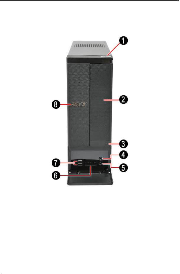
Front Panel
No. |
Component |
|
|
1 |
Power button/indicator |
|
|
2 |
Optical drive cover |
|
|
3 |
Optical drive eject button |
|
|
4 |
Headphone jack |
|
|
5 |
Microphone-in jack |
|
|
6 |
4-in-1 optional card reader supporting Memory Stick (MS), xD-Picture Card (xD), |
|
Secure Digital (SD), MultiMediaCard (MMC) and Memory Stick PRO (MS PRO) |
|
|
7 |
USB 2.0 ports |
|
|
8 |
Acer logo |
|
|
6 |
Chapter 1 |

Rear Panel
No. Component
1Line-in jack
2RJ45 LAN connector
3USB 3.0 ports
4PS2 mouse port
5Power connector
6PS2 keyboard port
7HDMI port
8D-sub port
9USB 2.0 ports
10Line-out jack
11Microphone jack
12Expansion slot
Chapter 1 |
7 |

Hardware Specifications and Configurations
Processor
Item |
Specification |
|
|
Processor Type |
Intel Ivy Bridge / Sandy Bridge Processor |
|
|
Socket Type |
LGA1155 |
|
|
Minimum operating speed |
0 MHz (If Stop CPU Clock in Sleep State in BIOS Setup is set to Enabled.) |
|
|
BIOS
Item |
Specification |
|
|
BIOS code programer |
AMI Kernel with Acer skin |
|
|
BIOS version |
P01-A0 |
|
|
BIOS ROM type |
SPI Flash |
|
|
BIOS ROM size |
64Mb |
|
|
Support protocol |
SMBIOS(DMI)2.7 |
|
|
Device Boot Support |
1st priority: SATA HDD |
|
2nd priority: CD-ROM |
|
3rd priority: Removable Device |
|
4th priority: LAN |
|
5th priority: USB device |
|
|
Support to LS-120 drive |
No |
|
|
Support to BIOS boot block feature |
YES |
|
|
BIOS Hotkey List
Hotkey |
Function |
Description |
|
|
|
Del |
Enter BIOS Setup Utility |
Press while the system is booting to enter BIOS Setup Utility. |
|
|
|
Main Board Major Chips
Item |
Specification |
|
|
Chipset |
Intel B75 |
|
|
USB controller |
Intel B75 |
|
|
Audio controller |
Intel B75+ALC662-VD |
|
|
LAN controller |
Intel 82579V |
|
|
SATA controller |
Intel B75 |
|
|
Super IO |
ITE 8772F |
controller |
|
|
|
8 |
Chapter 1 |

Memory Combinations
Slot |
Memory |
Total Memory |
|
|
|
Slot 1 |
1GB,2GB,4GB |
1G ~4GB |
|
|
|
Slot 2 |
1GB,2GB,4GB |
1G ~4GB |
|
|
|
Slot 3 |
1GB,2GB,4GB |
1G ~4GB |
|
|
|
Slot 4 |
1GB,2GB,4GB |
1G ~4GB |
|
|
|
Maximum System Memory Supported |
1G~16GB |
|
|
|
|
System Memory
Item |
Specification |
|
|
Memory slot number |
4 slot |
|
|
Support Memory size per socket |
1GB/2GB/4GB |
|
|
Support memory type |
DDRIII |
|
|
Support memory interface |
DDRIII 1333/1600MHz |
|
|
Support memory voltage |
1.5V |
|
|
Support memory module package |
240-pin DDRIII |
|
|
Support to parity check feature |
Yes |
|
|
Support to error correction code (ECC) feature |
No |
|
|
Memory module combinations |
You can install memory modules in any combination as long as |
|
they match the above specifications. |
|
|
Audio Interface
Item |
Specification |
|
|
|
|
Audio controller |
Intel PCH B75 |
|
|
|
|
Audio controller type |
ALC662-VD |
|
|
|
|
Audio channel |
codec 5.1 |
|
|
|
|
Audio function control |
Enable/disable by BIOS Setup |
|
|
|
|
Mono or stereo |
Stereo |
|
|
|
|
Compatibility |
The ALC662-VD supports host audio from Intel chipsets, and also from any |
|
|
other HDA compatible audio controller. With EAX/Direct Sound 3D/I3DL2 |
|
|
compatibility, software utilities like Karaoke mode, environment emulation, |
|
|
multi-band software equalizer, 3D positional audio, and optional Dolby R Digital |
|
|
Live and DTS R CONNECT ™ programs, the ALC662-VD provides an |
|
|
excellent home entertainment package and game experience for PC users. |
|
|
|
|
Music synthesizer |
No |
|
|
|
|
Sampling rate |
192 kHz (max.) |
|
|
|
|
MPU-401 UART support |
No |
|
|
|
|
Microphone&Headphone jack |
Supported |
|
|
|
|
|
|
|
Chapter 1 |
9 |

SATA Interface
Item |
Specification |
|
|
SATA controller |
Intel B75 |
|
|
Number of SATA channel |
SATA X 3(2 * SATA 3Gb/s, 1 * SATA 6Gb/s) |
|
|
Support mode |
AHCI/IDE mode option |
|
|
USB Port
Item |
Specification |
|
|
Universal HCI |
USB 2.0/1.1 or USB 3.0 |
|
|
USB Class |
Support legacy keyboard for legacy mode |
|
|
USB Connectors Quantity |
USB2.0: |
|
• Rear IO : * 4 ports |
|
• Internal Header: |
|
• *4 ports (2 * USB2.0 H5X2 Header) for B75 |
|
• All ports should meet USB IF spec and support 1A current over drive. |
|
USB3.0: |
|
Internal Header: * 2 ports. |
|
• One port support USB fast charging.(Meet USB battery charging spec. ver. |
|
1.2. , Apple charging including ipad.) The other port support standard USB |
|
3.0 downstream port. |
|
• Support fast charging in S0, S3, S4, S5, G3 to S5. |
|
• All ports should meet USB IF spec and support 2A capability for each port |
|
(S0). |
|
• reserve design for two USB 3.0 standard down stream ports. |
|
• Internal USB 3.0 H10x2 connector, follow the Industrial standard. |
|
• H2x1 with Vbus which is required to provide 3A current to front daughter |
|
board. |
|
• Charging IC is required for fast charger. (ODM proposed) |
|
• Rear IO: * 2 ports. |
|
• All ports should meet USB IF spec and support 2A capability for each port |
|
(S0). |
|
|
10 |
Chapter 1 |

Environmental Requirements
Item |
Specification |
|
|
Temperature |
|
|
|
Operating |
+5°C ~ +35°C |
|
|
Non-operating |
-20 ~ +60°C (Storage package) |
|
|
Humidity |
|
|
|
Operating |
15% to 80% RH |
|
|
Non-operating |
10% to 90% RH |
|
|
Vibration |
|
|
|
Operating (unpacked) |
5 ~ 500 Hz: 2.20g RMS random, 10 minutes per axis in all 3 axes. |
|
5 ~500 Hz: 1.09g RMS random, 1 hour per axis in all 3 axes. |
|
|
Power Management
Devices |
S1 |
S3 |
S4 |
S5 |
|
|
|
|
|
Power Button |
V |
V |
V |
V |
|
|
|
|
|
USB Keyboard/Mouse |
V |
V |
N/A |
N/A |
|
|
|
|
|
PME |
Disabled |
Disabled |
Disabled |
Disabled |
|
|
|
|
|
RCT |
Disabled |
Disabled |
Disabled |
Disabled |
|
|
|
|
|
WOR |
Disabled |
Disabled |
Disabled |
Disabled |
|
|
|
|
|
•Devices wake up from S3 should be less than.
•Devices wake up from S5 should be less than 10 seconds.
Chapter 1 |
11 |

Power Management Function(ACPI support function)
Device Standby Mode
•Independent power management timer for hard disk drive devices(0-15 minutes,time step=1minute).
•Hard Disk drive goes into Standby mode(for ATA standard interface).
•Disable V-sync to control the VESA DPMS monitor.
•Resume method:device activated (keyboard for DOS, keyboard &mouse for Windows.
•Resume recovery time 3-5sec
Global Standby Mode
•Global power management timer(2-120minutes,time step=10minute).
•Hard disk drive goes into Standby mode(for ATA standard interface).
•Disable H-sync and V-sync signals to control the VESA DPMS monitor.
•Resume method: Resume to original state by pushing external switch Button,modem ring in,keyboard an mouse for APM mode.
•Resume recovery time :7-10sec
Suspend Mode
•Independent power management timer(2-120minutes,time step=10minute)or pushing extern switch button.
•CPU goes into SMM
•CPU asserts STPCLK# and goes into the Stop Grant State.
•LED on panel turns amber colour.
•Hard disk drive goes into SLEEP mode (for ATA standard interface).
•Disable H-sync and V-sync signals to control the VESA DPMS monitor.
•Ultra I/O and VGA chip go into power saving mode.
•Resume method: Resume to original state by pushing external switch Button,modem ring in,keyboard an mouse for APM mode
•Return to original state by pushing external switch button,modem ring in and USB keyboard for ACPI mode.
ACPI
•ACPI specification 1.0b
•S0,S1,S2 and S5 sleep state support.
•On board device power management support.
•On board device configuration support.
12 |
Chapter 1 |
Chapter 2
System Utilities
CMOS Setup Utility
CMOS setup is a hardware configuration program built into the system ROM, called the complementary metaloxide semiconductor (CMOS) Setup Utility. Since most systems are already properly configured and optimized, there is no need to run this utility. You will need to run this utility under the following conditions.
•When changing the system configuration settings
•When redefining the communication ports to prevent any conflicts
•When modifying the power management configuration
•When changing the password or making other changes to the security setup
•When a configuration error is detected by the system and you are prompted ("Run Setup" message) to make changes to the CMOS setup
NOTE: If you repeatedly receive Run Setup messages, the battery may be bad. In this case, the system cannot retain configuration values in CMOS. Ask a qualified technician for assistance.
CMOS setup loads the configuration values in a battery-backed nonvolatile memory called CMOS RAM. This memory area is not part of the system RAM which allows configuration data to be retained when power is turned off.
Before you run the CMOS Setup Utility, make sure that you have saved all open files. The system reboots immediately after you close the Setup.
NOTE: CMOS Setup Utility will be simply referred to as “BIOS”, "Setup", or "Setup utility" in this guide.
The screenshots used in this guide display default system values. These values may not be the same those found in your system.
Chapter 2 |
13 |

Entering CMOS setup
1.Turn on the server and the monitor.
If the server is already turned on, close all open applications, then restart the server.
2.During POST, press Delete.
If you fail to press Delete before POST is completed, you will need to restart the server.
The Setup Main menu will be displayed showing the Setup’s menu bar. Use the left and right arrow keys to move between selections on the menu bar.
Navigating Through the Setup Utility
Use the following keys to move around the Setup utility.
•Left and Right arrow keys – Move between selections on the menu bar.
•Up and Down arrow keys – Move the cursor to the field you want.
•PgUp and PgDn keys – Move the cursor to the previous and next page of a multiple page menu.
•Home – Move the cursor to the first page of a multiple page menu.
•End – Move the cursor to the last page of a multiple page menu.
•+ and - keys – Select a value for the currently selected field (only if it is user-configurable). Press these keys repeatedly to display each possible entry, or the Enter key to choose from a pop-up menu.
NOTE: Grayed-out fields are not user-configurable.
•Enter key – Display a submenu screen. NOTE: Availability of submenu screen is indicated by a (>).
•Esc – If you press this key:
•On one of the primary menu screens, the Exit menu displays.
•On a submenu screen, the previous screen displays.
•When you are making selections from a pop-up menu, closes the pop-up without making a selection.
•F1 – Display the General Help panel.
•F6 – Press to load optimized default system values.
•F7 – Press to load fail-safe default system values.
•F10 – Save changes made the Setup and close the utility.
14 |
Chapter 2 |
Setup Utility Menus
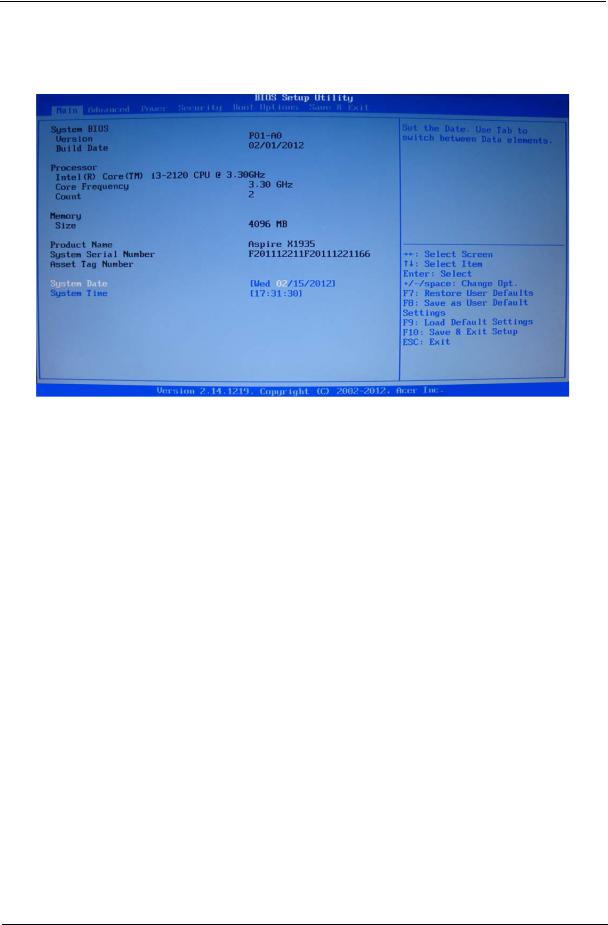
Main
The Setup Main menu includes the following main setup categories.
Parameter |
Description |
|
|
System BIOS |
|
|
|
Version |
Version number of the BIOS setup utility. |
|
|
Build Date |
Date when the BIOS setup utility was built |
|
|
Processor |
Type of CPU installed on the system. |
|
|
Core Frequency |
Core speed of the CPU installed on the system. |
|
|
Count |
Physical CPU count |
|
|
Memory |
|
|
|
Size |
Total size of system memory installed on the system. |
|
|
Product Name |
Product name of the system. |
|
|
System Serial Number |
Serial number of the system. |
|
|
Asset Tag Number |
Asset tag number of this system. |
|
|
System Date |
Set the date following the weekday-month-day-year format. |
|
|
System Time (hh:mm:ss) |
Set the system time following the hour-minute-second format. |
|
|
In the descriptive table following each of the menu screenshots, settings in boldface are the default and suggested settings.
Chapter 2 |
15 |
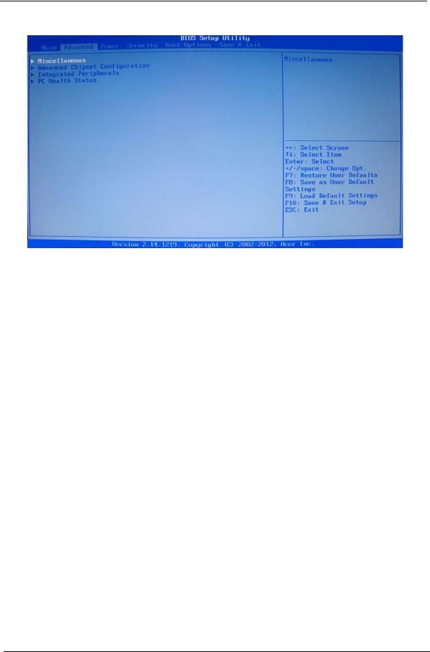
Advanced
Parameter |
Description |
|
|
Miscellaneous |
Press Enter to access the Miscellaneous submenu |
|
|
Advanced Chipset Configuration |
Press Enter to access the Advanced Chipset Configuration submenu |
|
|
Integrated Peripherals |
Press Enter to access the Integrated Peripherals submenu |
|
|
PC Health Status |
Press Enter to access the PC Health Status submenu |
|
|
16 |
Chapter 2 |

Miscellaneous
Parameter |
Description |
Option |
|
|
|
AHCI Port0/1/2 |
Displays the status of auto detection of the AHCI device. |
|
|
|
|
Bootup Num-lock |
Selects power on state for Num Lock. |
On |
|
|
Off |
|
|
|
USB Beep Message |
Enables or disables BIOS to display error beeps or messages during USB |
Enabled |
|
device enumeration. |
Disabled |
|
|
|
Chapter 2 |
17 |
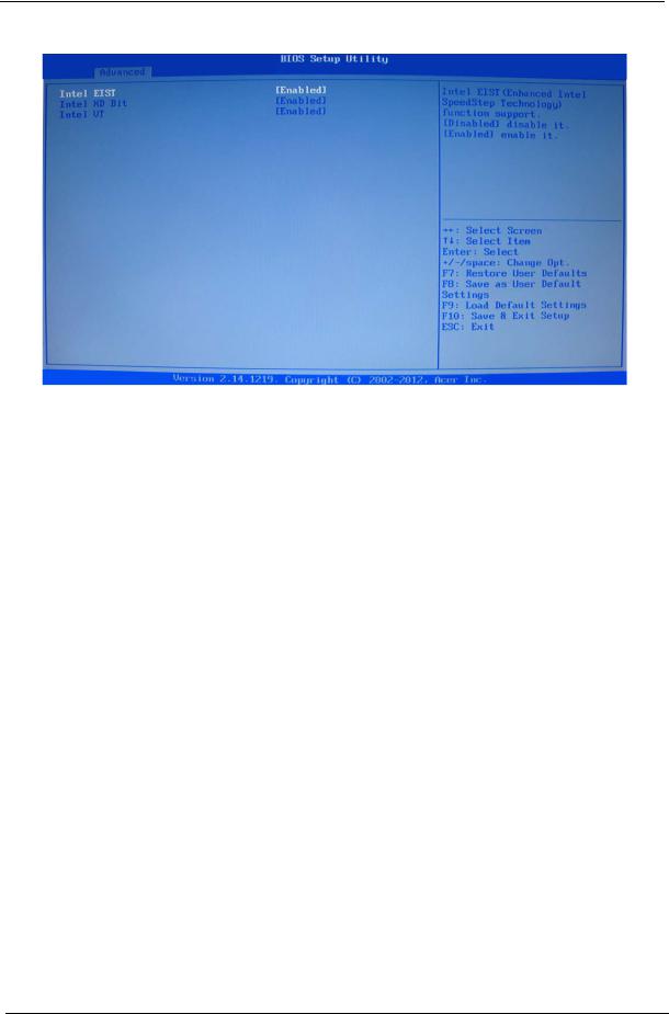
Advanced Chipset Configuration
Intel EIST |
When enabled, this feature allows the OS to reduce power consumption. |
Enabled |
|
When disabled, the system operates at maximum CPU speed. |
Disabled |
|
|
|
Intel XD Bit |
When enabled, the processor disables code execution when a worm |
Enabled |
|
attempts to insert a code in the buffer preventing damage and worm |
Disabled |
|
propagation. |
|
|
When disabled, the processor forces the Execute Disable (XD) Bit feature |
|
|
flag to always return to 0. |
|
|
|
|
Intel VT |
Enables or disables the Virtualization Technology (VT) availability. If |
Enabled |
|
enabled, a virtual machine manager (VMM) can utilize the additional |
Disabled |
|
hardware virtualization capabilities provided by this technology. |
|
|
Note: A full reset is required to change the setting. |
|
|
|
|
18 |
Chapter 2 |
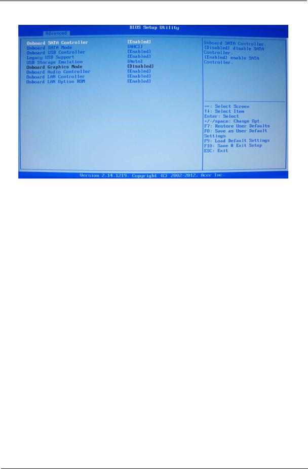
Integrated Peripherals
Parameter |
Description |
Option |
|
|
|
Onboard SATA Controller |
Enables or disables the onboard SATA controller. |
Enabled |
|
|
Disabled |
Onboard SATA Mode |
Select an operating mode for the onboard SATA. |
Native IDE |
|
|
AHCI |
Onboard USB Controller |
Enables or disables the onboard USB controller. |
Enabled |
|
|
Disabled |
Legacy USB Support |
Enables or disables support for legacy USB devices. |
Enabled |
|
|
Disabled |
USB Storage Emulation |
If Auto, USB device equal or less than 2GB will be emulated as Floppy |
Auto |
|
and remaining as harddrive. Forced FDD option can be used to force a |
Floppy |
|
HDD formatted drive to boot as FDD (Ex.ZIP drive). |
Hard Disk |
|
|
|
Onboard Graphics |
Enables or disables the onboard Graphics Controller. |
Enabled |
Controller |
|
Disabled |
|
|
|
Onboard Audio Controller |
Enables or disables the onboard audio controller. |
Enabled |
|
|
Disabled |
|
|
|
Onboard LAN Controller |
Enables or disables the onboard LAN controller. |
Enabled |
|
|
Disabled |
|
|
|
Onboard LAN Option ROM |
Enables or disables the load of embedded option ROM for onboard |
Enabled |
|
network controller. |
Disabled |
|
|
|
Chapter 2 |
19 |
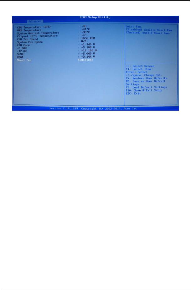
PC Health Status
Parameter |
Description |
Option |
|
|
|
Smart Fan |
Enables or disables the smart system fan control function. |
Enabled |
|
|
Disabled |
|
|
|
20 |
Chapter 2 |
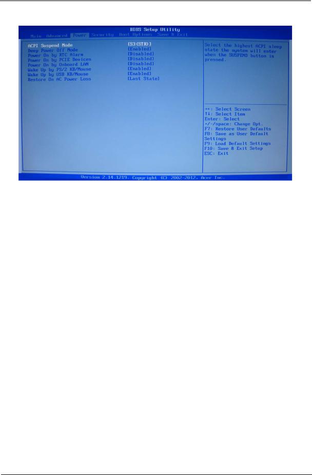
Power
Parameter |
Description |
Option |
|
|
|
ACPI Suspend Mode |
Select an ACPI state. |
S3 (STR) |
|
|
S1 (POS) |
|
|
|
Deep Power Off Mode |
Select the Deep power off Mode |
Enabled |
|
|
Disabled |
|
|
|
Power On by RTC Alarm |
Enables or Disables to wake up the system by RTC Alarm Function |
Enabled |
|
|
Disabled |
|
|
|
Power On by PCIE Devices |
This system can be turned off with a software commend. If you enable |
Enabled |
|
this item, the system can automatically resume if there is an incoming |
Disabled |
|
call on the PCIE LAN card.You must use an ATX power supply in order |
|
|
to use this feature.Use this item to dowake-up action if inserting the |
|
|
PCIE card. |
|
|
|
|
Power On by Onboard LAN |
Enables or disables an onboard LAN controller to generate a wake |
Enabled |
|
event. |
Disabled |
Wake Up by PS/2 KB/ |
Enables or disables to wake up the system from a power saving mode |
Enabled |
Mouse |
using a PS2 keyboard or mouse. |
Disabled |
|
|
|
Wake Up by USB KB/ |
If enabled, press any key or click the mouse will wake system from S1/ |
Enabled |
Mouse |
S3 state. |
Disabled |
|
|
|
Restore On AC Power Loss |
Enables or disables the system to reboot after a power failure or |
Off |
|
interrupt occurs. |
On |
|
|
Last State |
Chapter 2 |
21 |
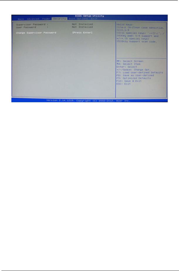
Security
Parameter |
Description |
Option |
|
|
|
Supervisor Password |
This item indicates whether a supervisor password has been set. If the password has been |
|
|
installed, Installed displays. If not, Not Installed displays. |
|
|
|
|
User Password |
This item allows you to change user password. |
|
|
|
|
Change Supervisor |
You can select this option and press <Enter> to access the sub menu. You can use the sub |
|
Password |
menu to change the supervisor password. |
|
|
|
|
Setting a supervisor password
1.Use the up/down arrow keys to select Change Supervisor Password menu then press Enter. A password box will appear.
2.Type a password then press Enter.
The password may consist up to six alphanumeric characters (A-Z, a-z, 0-9)
3.Retype the password to verify the first entry then press Enter again.
4.Press F10.
5.Select Yes to save the new password and close the Setup Utility.
Changing the supervisor password
1.Use the up/down arrow keys to select Change Supervisor Password menu then press Enter.
2.Type the original password then press Enter.
3.Type a new password then press Enter.
4.Retype the password to verify the first entry then press Enter again.
5.Press F10.
6.Select Yes to save the new password and close the Setup Utility.
Removing a supervisor password
1.Use the up/down arrow keys to select Change Supervisor Password menu then press Enter.
2.Enter the current password then press Enter.
3.Press Enter twice without entering anything in the password fields.
22 |
Chapter 2 |
Loading...