

Page 1

9133i IP PHONE
INSTALLATION
Release # 1.0
GUIDE
DRAFT
Page 2

SOFTWARE LICENSE AGREEMENT
Aastra Telecom Inc., hereinafter known as "Seller", grants to Customer a personal, worldwide, non-transferable, non-sublicenseable and non-exclusive,
restricted use license to use Software in object form solely with the Equipment for
which the Software was intended. This Product may integrate programs, licensed
to Aastra by third party Suppliers, for distribution under the terms of this agreement. These programs are confidential and proprietary, and are protected as such
by copyright law as unpublished works and by international treaties to the fullest
extent under the applicable law of the jurisdiction of the Customer. In addition,
these confidential and proprietary programs are works conforming to the requirements of Section 401 of title 17 of the United States Code. Customer shall not disclose to any third party such confidential and proprietary programs and
information and shall not export licensed Software to any country except in accordance with United States Export laws and restrictions.
Customer agrees to not reverse engineer, decompile, disassemble or display Software furnished in object code form. Customer shall not modify, copy, reproduce,
distribute, transcribe, translate or reduce to electronic medium or machine readable form or language, derive source code without the express written consent of
the Seller and its Suppliers, or disseminate or otherwise disclose the Software to
third parties. All Software furnished hereunder (whether or not part of firmware),
including all copies thereof, are and shall remain the property of Seller and its
Suppliers and are subject to the terms and conditions of this agreement. All rights
reserved.
Customer's use of this software shall be deemed to reflect Customer's agreement
to abide by the terms and conditions contained herein. Removal or modification of
trademarks, copyright notices, logos, etc., or the use of Software on any Equipment other than that for which it is intended, or any other material breach of this
Agreement, shall automatically terminate this license. If this Agreement is terminated for breach, Customer shall immediately discontinue use and destroy or
return to Seller all licensed software and other confidential or proprietary information of Seller. In no event shall Seller or its suppliers or licensors be liable for any
damages whatsoever (including without limitation, damages for loss of business
profits, business interruption, loss of business information, other pecuniary loss,
or consequential damages) arising out of the use of or inability to use the software, even if Seller has been advised of the possibility of such damages.
Page 3

Table of Contents
Introduction ..................................................................................................1
Phone Features ..........................................................................................1
Requirements .............................................................................................1
About This Guide ........................................................................................1
Phone Parts ................................................................................................2
Key Description ...........................................................................................3
Key Description ...........................................................................................4
Installation and Setup .................................................................................5
Direct Network Connection .........................................................................5
Connecting to the Network and to Power ...................................................5
Power Adapter ............................................................................................5
Connecting a Handset or Headset ..............................................................5
Headset (Optional) ......................................................................................6
Desk or Wall Installation ..............................................................................6
Install on the Desk ......................................................................................6
Install on the Wall ........................................................................................6
Inserting Number Card ...............................................................................7
Insert the Memory key card on your telephone ..........................................7
Customizing your phone .............................................................................8
Setting your Options ...................................................................................8
Other Phone Features ...............................................................................10
Adjusting the Volume ................................................................................10
Status Lights .............................................................................................10
Speaker Light ............................................................................................10
Telephone Light ........................................................................................10
Timer .........................................................................................................10
Programmable keys ..................................................................................10
Using a Headset with your Telephone .......................................................10
Making and Receiving Calls
using a Headset .....................................................................................10
Troubleshooting .........................................................................................11
Limited Warranty .......................................................................................12
Table of Contents
Page 4

Introduction
Congratulations on your purchase of the Model 9133i IP Phone! The 9133i
communicates over an IP Network, allowing you to receive and place calls in
the same manner as a regular business telephone. This release of the 9133i is
capable of supporting the SIP protocol.
Phone Features
• Three line adjustable backlit display screen
• 3 line/call appearance buttons with corresponding lights
• 7 programmable keys with lights - can be programmed as speed dials/
memory keys, or additional Line/Call appearances
• Speakerphone for handsfree
Introduction
• Built-in-two-port, 10/100 Ethernet switch which lets you share a connection with your computer
• Inline power support, which eliminates power adapters.
Requirements
• SIP based IP PBX system or network installed and running with a number created for the 9133i phone.
• Access to a Trivial File Transfer Protocol (TFTP) server.
• 802.3 Ethernet/Fast Ethernet LAN.
• Category 5/5e straight through cabling.
• Power over Ethernet (PoE) power supply (optional accessory - necessary
only if no inline power is provided on the network).
About This Guide
This manual describes how to physically set up your new 9133i. Not all
features listed are available by default and some may depend on your phone
system or service provider. Contact your system administrator if you have
any questions on what features and services are available to you on your
system. This guide complements the
and the
Aastra Model 9133i Administrator Guide
administrators, system administrators, developers and partners who need
information on installing this product on an IP network.
Aastra Model 9133i User Guide
telephone features for an end user.
These guides along with release notes, system updates, etc. can be
downloaded from our website at www
Aastra Model 9133i User Guide
Aastra Model 9133i Administrator Guide
.
– is designed for network
– explains the most commonly used IP
.aastra.com/EnterpriseIP
1
Model 9133i Installation Guide
Page 5
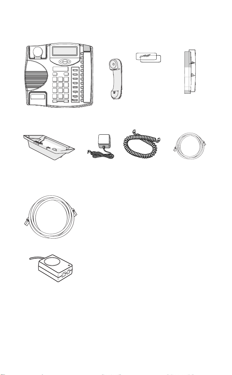
Phone Parts
When you unpack your phone, you should ensure that you have all of the
following items. If any part is missing, contact the supplier of your phone.
Number card
and plastic lens
Introduction
Handset
Telephone
Telephone stand
Power adaptor
Optional Accessories (Not Included
Additional Ethernet Cable
(category 5/5e straight
through cable)
PoE (Power over
Ethernet) Inline Power
Supply
Handset cord
Memory key card
and plastic lens
Ethernet Cable
A PoE (Power over Ethernet) inline power adapter supplies 48v power to the
9133i through the Ethernet Cable on pins 1 & 2 and 3 & 6. Do not use this
power supply to power other devices.
•
Voltage:
Safety and emissions:
110/120 V AC in; 48 V DC out
Canada: ICES-003 Class A; Japan: VCCI Class A;
U.S.: FCC Class A, CSA, C-Tick, NOM
Model 9133i Installation Guide
2
Page 6

Key Description
Set Indicator Light
Options Key
Backlit Display
Navigational Keys
Handset
Key Description
Options
Directory
Conf
Xfer
L3
L2
L1
Save
Delete
Volume Bar
Dial Pad
Line/Call Appearence Keys and Lights
14 Memory Keys
3
Mute
Model 9133i Installation Guide
Page 7

Key Description
Keys Key Description
O
N
n
l
k
m
f
g
h
P
R
S
I
J
K
L
o
e Pressing e activates Handsfree so you can make and receive calls
Places an active call on hold. To retrieve a held call, press the call
appearance button beside the light that is flashing.
Pressing N ends an active call. N also exits an open list, such as
I
, without saving changes.
Access a list of the last 200 calls received.
Pressing l
your
9133i User Guide
Pressing k
your
9133i User Guide
Redials up to ten previously dialed numbers.
Pressing one of the line or call appearance buttons connects you to a
line or call. * See your
Activates the speaker and microphone so you can listen and talk without using the handset; also mutes the microphone so that your caller
cannot hear you (the light indicator will flash when the microphone is
muted).
Adjusts the volume for the handset, headset, ringer and handsfree
speaker. See
Pressing W
begins a conference call with the active call. * See
for further information.
transfers the active call to another number. * See
for further information.
9133i User Guide
“Adjusting the Volume” on page 11
and V
lets you move between screens. These but-
for further information.
for more information.
tons also let you scroll through menu selections, such as the
Options List. Pressing T
and U
in the options list will also cancel
or show the current option. When you are editing entries on the
display, T
The Ibutton lets you access options to customize your phone.
Your System Administrator may have already customized some of
your settings. Check with your System Administrator before changing
any System Administrator only sections.
Stores up to 200 names and phone numbers (stored in alphabetical order).
Use to store numbers and names in Directory, in memory keys and to
save Option feature settings.
Removes individual entries in the Directory, or Callers List. Erases
memory key information.
Places a current call on hold and answer an incoming call. Pressing
moves the cursor left and U
moves the cursor right.
o again will alow you to switch between two active calls.
without lifting the handset. When the audio mode option is activated,
this key is used to switch between a headset and the Handsfree speakerphone. See “Customizing your phone” on page 9 for more information.
Pressing one of the line or call appearance buttons connects you to a
M
line or call. * See your 9133i User Guide for further information.
Key Description
*Availability of feature dependant on your phone system or service provider
Model 9133i Installation Guide
4
Page 8

Installation and Setup
The 9133i can be setup to share a network connection with another network
device. Power can be provided by an 802.3af compliant network power
source or with a PoE inline power supply (optional accessory). It can also be
installed on a desk or mounted on the wall. If your System Administrator has
already setup your phone, please refer to the (if provided) for call handling
information or talk to your System Administrator.
Direct or Shared Network Connection
The phone can be set up as a direct network connection to the Ethernet wall
jack or as a shared network connection as a pass-through if connecting the
phone to a computer or another network device.
Direct Network Connection
Ethernet
Cable
To Network
Network Jack
(if Inline power provided)
Located at the back of the phone
are two fully switched 10/100
Mbps Ethernet cable ports. The
port marked with l is used to
connect the phone to the
network, as well as provide
power to your phone. See the
Installation and Setup
section “Connecting to the
Separate
Network
Jack
Other Network Devices
Network and to Power” on
page 6 for more information.
Shared Network Connection
To Other
Network Device
To connect a network device
(such as a computer) to the
To Network
phone, connect an Ethernet Cable
into the network port on the back
of the phone marked with ;.
Plug the other end of the
Ethernet Cable into the network
jack on the network device you
are sharing the network
Other Network Devices
Network Jack
(if Inline power provided)
connection with.
Ethernet
Cable
Note: The ; jack on the 9133i does not supply inline power onto other network devices.
All Ethernet cables used must be category 5/5e straight-through cables, such as
the cable provided with your phone
5
Model 9133i Installation Guide
Page 9

Connecting to the Network and to Power
Inline Power Provided
If your network provides 802.3af compliant
in-line power, the phone is powered
through the network.
1. On the back of your phone, connect the
Ethernet Cable (provided with your
phone) into the network port marked
with l.
2. Plug the other end of the Ethernet Cable
directly into the network jack on the wall.
Ethernet
Cable
To Network
Network Jack
(if Inline power provided)
Inline Power Not Provided
If your network does not provide 802.3af compliant in-line power, you have
to install the PoE inline power supply (optional accessory).
1. On the back of your phone, connect
the Ethernet Cable (provided with
your phone) into the network port
marked with l.
2. On the PoE power supply, plug the
other end of the Ethernet Cable into the
network jack marked as indicated below.
3. On the PoE power supply, connect an
additional Ethernet Cable (provided
with the power supply) into the network
port as indicated below.
4. Plug the other end of the Ethernet Cable
into the network jack on the wall.
5. Plug the PoE power supply into a
power outlet.
Ethernet
Cable
To Phone
To POE
Power Supply
POE
Power Supply
(if Inline power is
not provided)
To Network
Network Jack
Jack
Installation and Setup
Note: You should connect the power supply to a surge protector or power bar. All
Ethernet cables used must be category 5/5e straight-through cables, such as
the cable provided with your phone.
Connecting a Handset or Headset
Handset
Turn the phone over and locate the
handset jack marked j. Insert one end
of handset cord into the jack until it clicks
into place. Then route the handset cord
through the upper groove as shown in the
next illustration. Attach the handset to the
other end of the handset cord.
Model 9133i Installation Guide
To Handset
To Headset
6
Page 10

Headset (Optional)
Turn the phone over and locate the headset jack marked f. Insert the headset
cord into the jack until it clicks into place. Then route the headset cord
through the lower groove as shown in the previous illustration.
Desk or Wall Installation
Install on the Desk
Route the cables through the opening
in the stand. Attach the stand by
inserting the tabs on the stand (marked
with o) into the slots on the bottom of
the phone. For a higher viewing angle,
use the slots marked n.
For a lower viewing angle, use the slots
marked m. Then push the stand
towards the phone until it snaps into
place. Press the cords into the grooves
provided on the bottom of the stand. This will allow the stand to sit flat on
a desk surface.
Installation and Setup
Install on the Wall
Connect the Ethernet cable to the wall
network jack (A). Coil the cable into the
space provided on the back of the
phone (B). Then align the phone so the
hooks on the wall plate (C) align with
the wall-mount slots on the back of the
phone, as shown here. Push the phone
onto the pegs, and then slide it down
until it is secure (D).
Note: You may wish to purchase a short
Ethernet cable from a local supplier
for a wall installation. Also, if 802.3af
compliant in-line power is not provided on your network and you are
installing the 9133i on a wall using a PoE in-line power supply, you may also
wish to use an equivalent flat Ethernet cable rather than the one provided.
7
Model 9133i Installation Guide
Page 11

Inserting Number Card
Write your phone number on the number card, and place it into the card slot
on the phone, located under the mouthpiece in the handset cradle. Gently
bend the clear plastic lens into the slot, over the number card.
Insert the Memory key card on your telephone
This card contains the feature names for the dedicated keys and label identification spaces for the two programmable memory keys.
Place the card into the memory key card slot on the telephone.
Gently bend the clear plastic lens and place it on top of the memory key card
in the slot.
Installation and Setup
Model 9133i Installation Guide
Call Fwd
Clinic
Options
Directory
Save
Delete
Shift
8
Page 12

Customizing your phone
There is a list of configuration
options, accessed by pressing the
Ibutton.
Setting your Options
1. Press the I button on the
phone to enter the options list.
2. To go to an Option, use the V
and W to scroll through the list
or press the number
corresponding to the Option.
3. To select an Option, press the 4
button beside the Option you
want.
4. Use the W to save the change
and exit the current option.
5. Press the V
any time to exit without saving
the changes.
The following options are
configurable on the 9133i IP Phone:
or N or button at
Customizing your phone
1. Language
Select a language for the display
prompts.
Note: Supported languages may vary.
2. Time and Date
Use these options to set the local
time on the phone. Depending upon
the configuration, time set here may
be overwritten by the time on your
phone system. If you are having
problems with this, contact your
System Administrator.
A) Timeserver
Talk to your System Administrator
before making changes to this
option.
If the Timeserver option is
enabled, the display shows the IP
address where the phone is
getting time and date
information from on the
Network. Whenever the 9133i IP
Phone starts up, it
automatically attempts to find
the Timeserver. If the Timeserver
unknown to the 9133i, the IP
address displays as 0.0.0.0, and
the time and date in the main
screen displays 12:00 am Jan. 1st
2000. If the time server option is
disabled, the display shows
“Network Time Disabled”. You
can set the time and date
manually on your phone.
B) Set Time
This option shows the Network
time, if the Timeserver option is
enabled. If the Timeserver is not
enabled, this option allows you
to enter the time manually.
C) Time Format
Select a time format for how time
is displayed on your phone (12h
or 24h clock).
D) Set Date
This option shows the Network
date, if the Timeserver option is
enabled. If the Timeserver is not
enabled, this option allows you
to enter the date manually.
E) Date Format
Choose from a list of formats for
how date is displayed on your
phone.
F) Timezone
Choose your current time zone
from a list of time zones.
G) Daylight Savings
This option allows you to specify
daylight savings.
3. Set Ring Tone
Use the W and V to scroll
through the list and select an
Option. Use the volume bar to
increase or decrease the ringer
volume level.
9
Model 9133i Installation Guide
Page 13

4. Clear Message Waiting
Use the W and V to scroll to the
option and press W to delete. The
light flashes again when there are
new messages waiting.
5. Contrast Level *
Use the Change softkey to cycle
through 8 contrast settings, which
brighten or darken the display.
6. Live Dial Pad*
Turn on or off the dial pad mode.
With Live Dial Pad ON, the 9133i IP
Phone automatically dials out and
turns ON Hands free mode as soon
as a dial pad key is pressed. With
Live Dial Pad OFF, you must dial
the number first and then lift the
handset or press the e before the
number is dialed. Press the e to
turn the dial pad mode on or off.
7. Headset Settings
The 9133i allows you to use a
handset, a headset or handsfree to
handle incoming and outgoing
calls. This option provides different
combinations of these three
methods to provide maximum
flexibility in handling calls. There
are four options to choose from:
• Handsfree — this is the default
setting. Calls can be made or
received using the handset or
handsfree speakerphone and can
be switched between the two
modes by pressing the e button on the phone. When on
handsfree, you can return to
using the handset by placing the
handset on the cradle and picking it up again.
• Headset — choose this setting if
you want to make or receive all
calls using a headset. Calls can be
switched between the headset
and handset by pressing the e
button on the phone.
• Spkr/Hset — incoming calls are
sent to the handsfree speaker-
phone. By pressing the e button on the phone you can switch
between the handsfree speakerphone, the headset and the handset.
• Hset/Spkr — calls are sent to the
headset. By pressing e
button on the phone you can
switch between the headset,
the handsfree speakerphone
and the handset.
Additional settings in the options
menu are specific to the firmware
version you have in your 9133i IP
Phone.
8. Network Settings
This a system administrator level
only option, and requires a
password to access. See the 9133i
Administrator Guide for details.
9. SIP Settings
This a system administrator level
only option, and requires a
password to access. See the 9133i
Administrator Guide for details.
10. Phone Status
See “Status Lights” on page 11.
Talk to your System Administrator
before changing your phone
settings.
*Availability of feature dependant on
your phone system or service provider or
version of the 9133i you are using.
the
Customizing your phone
Model 9133i Installation Guide
10
Page 14

Other Phone Features
Adjusting the Volume
Pressing the volume button
u adjusts the receiver,
headset, speaker, and ringer
volume.
• To adjust the ringer volume,
leave the handset in the cradle
and press the volume button
u while there is no active
call. There are 8 settings for the
ringer — the display temporarily indicates the current ringer
volume setting.
• To adjust the handset volume, lift
the handset and press the volume
button while you are on a call.
The handset remains at this volume until it is adjusted again.
• To adjust the headset volume,
press the volume button while
you are on a call. The headset
Other Phone Features
remains at this volume until it is
adjusted again.
• To adjust the speaker volume,
press the volume button while
the speaker is activated (activate
the speaker by pressing e).
The speaker remains at this volume until it is adjusted again.
Timer
• When you make or answer a call,
Programmable keys
The 9133i has 7 programmable
keys that can be programmed for
speed dial or configured as extra
line keys. Contact your System
Administrator or see the 9133i User
Guide for more information on
programmable keys.
U
phone
The 9133i accepts headsets through
the modular RJ22 jack on the back of
the phone. Contact your telephone
equipment retailer or distributor to
purchase a compatible headset.
Customers should read and observe
all safety recommendations
contained in headset operating
guides when using any headset.
Making and Receiving Calls
using a Headset
1. Ensure that you have selected a
Status Lights
Speaker Light
• Speaker light is on solid.
A call is on Handsfree (speakerphone).
• Speaker light flashes slowly.
The headset is being used.
• Speaker light flashes quickly.
The call is muted. Press e to
take the call off mute.
2. Plug the headset into jack.
3. Press the ef key to obtain dial
4. Press the N key to end the call.
Telephone Light
• Light flashes slowly.
There are un-heard messages.
• Light flashes quickly and the
ringer sounds.
There is an incoming call.
the Timer shows the elapsed time
of the call.
sing a Headset with your Tele-
headset audio mode by accessing
the Options menu. See
“Customizing your phone” on
page 9 for detailed information.
tone or answer an incoming call.
Depending on the Headset mode
selected from the Options menu a
dial tone or an incoming call is
received on either the headset or
the handsfree speakerphone.
11
Model 9133i Installation Guide
Page 15

Troubleshooting
Why is the light not coming on
with a new Voice Mail Message?
Your phone system or service
provider must provide “Visual”
Message Waiting service for this
function to work. Check with your
System Administrator for more
information.
Why is my handset not working?
Check to ensure that the handset
cord is fully connected to both the
phone and handset. See
“Connecting a Handset or
Headset” on page 6 for
information.
Why is my speakerphone
not working?
If you press e and the speaker
light flashes and you do not hear
dial tone, the Set Headset option has
been used to set up the phone for
headset use; press e a second
time. If the light goes out, the phone
is set up to be used only with a
headset or handset. If the light stays
on steady and you hear dial tone,
you can alternate between the
speakerphone and the headset by
pressing e. See “Customizing
your phone” on page 9 for
instructions on how to change
Headset Settings.
Why can I only see 4 options
when the installer or User Guide
says there are more?
The telephone screen only shows 4
options at a time. To see more, press
the down arrow button V.
How do I remove the stand from
the phone?
Place one hand on top of the phone,
and place the other hand on the top
of the stand. Pull the stand away
from the telephone. You have to
pull quite forcefully, but it should
not break the stand.
Can I turn the light on the screen
off?
No. You can only adjust the contrast
of the display.
Why does the telephone wobble?
Make sure the cords are routed
properly through the stand, as
indicated in “Desk or Wall
Installation” on page 7. Check that
the stand has been properly
snapped into place.
Troubleshooting
Why is my display blank?
Ensure that power is being
provided to your phone. If your
Network does not provide Inline
power over Ethernet, you can
obtain an additional accessory, the a
PoE inline power supply, to
provide power over Ethernet
locally to your phone. See
“Connecting to the Network and to
Power” on page 6 for details.
Model 9133i Installation Guide
12
Page 16

Limited Warranty
Aastra Telecom warrants this product
against defects and malfunctions
during a one (1) year period from the
date of original purchase. If there is a
defect or malfunction, Aastra Telecom
shall, at its option, and as the exclusive
remedy, either repair or replace the
telephone set at no charge, if returned
within the warranty period.
If replacement parts are used in
making repairs, these parts may be
refurbished, or may contain
refurbished materials.
If it is necessary to replace the
telephone set, it may be replaced with
a refurbished telephone of the same
Limited Warranty
design and color. If it should become
necessary to repair or replace a
defective or malfunctioning telephone
set under this warranty, the provisions
of this warranty shall apply to the
repaired or replaced telephone set
until the expiration of ninety (90) days
from the date of pick up, or the date of
shipment to you, of the repaired or
replacement set, or until the end of the
original warranty period, whichever is
later. Proof of the original purchase
date is to be provided with all
telephone sets returned for warranty
repairs.
Exclusions
Aastra Telecom does not warrant its
telephone sets to be compatible with
the equipment of any particular
telephone company. This warranty
does not extend to damage to products
resulting from improper installation or
operation, alteration, accident, neglect,
abuse, misuse, fire or natural causes
such as storms or floods, after the
telephone is in your possession.
Aastra Telecom shall not be liable for
any incidental or consequential
damages, including, but not limited to,
loss, damage or expense directly or
indirectly arising from the customers
use of or inability to use this
telephone, either separately or in
combination with other equipment.
This paragraph, however, shall not
apply to consequential damages for
injury to the person in the case of
telephones used or bought for use
primarily for personal, family or
household purposes.
This warranty sets forth the entire
liability and obligations of Aastra
Telecom with respect to breach of
warranty, and the warranties set forth
or limited herein are the sole
warranties and are in lieu of all other
warranties, expressed or implied,
including warranties or fitness for
particular purpose and
merchantability.
Warranty Repair Services
Should the set fail during the warranty
period;
In North America, please call
1-800-574-1611 for further information.
Outside North America, contact your
sales representative for return
instructions.
You will be responsible for shipping
charges, if any. When you return this
telephone for warranty service, you
must present proof of purchase.
After Warranty Service
Aastra Telecom offers ongoing repair
and support for this product. This
service provides repair or replacement
of your Aastra Telecom product, at
Aastra Telecom's option, for a fixed
charge. You are responsible for all
shipping charges. For further
information and shipping instructions;
In North America, contact our service
information number: 1-800-574-1611.
Outside N
sales representative.
Note:
orth America, contact your
Repairs to this product may be made
only by the manufacturer and its
authorized agents, or by others who
are legally authorized. This restriction
applies during and after the warranty
period. Unauthorized repair will
void the warranty.
41-0X0X-00 Rev. 00
13
Model 9133i Installation Guide
 Loading...