

Page 1
Aastra Model 6865i SIP IP Phone
User Guide
Release 3.3.1 SP3
41-001523-00 REV00 – 04.2014
Page 2

Software License Agreement
Aastra, hereinafter known as "Seller", grants to Customer a personal, worldwide, non-transferable, non-sublicenseable
and non-exclusive, restricted use license to use Software in object form solely with the Equipment for which the Software was intended. This Product may integrate programs, licensed to Aastra by third party Suppliers, for distribution
under the terms of this agreement. These programs are confidential and proprietary, and are protected as such by copyright law as unpublished works and by international treaties to the fullest extent under the applicable law of the jurisdiction of the Customer. In addition, these confidential and proprietary programs are works conforming to the requirements of Section 401 of title 17 of the United States Code. Customer shall not disclose to any third party such confidential and proprietary programs and information and shall not export licensed Software to any country except in accordance with United States Export laws and restrictions.
Customer agrees to not reverse engineer, decompile, disassemble or display Software furnished in object code form.
Customer shall not modify, copy, reproduce, distribute, transcribe, translate or reduce to electronic medium or machine
readable form or language, derive source code without the express written consent of the Seller and its Suppliers, or disseminate or otherwise disclose the Software to third parties. All Software furnished hereunder (whether or not part of
firmware), including all copies thereof, are and shall remain the property of Seller and its Suppliers and are subject to the
terms and conditions of this agreement. All rights reserved.
Customer's use of this software shall be deemed to reflect Customer's agreement to abide by the terms and conditions
contained herein. Removal or modification of trademarks, copyright notices, logos, etc., or the use of Software on any
Equipment other than that for which it is intended, or any other material breach of this Agreement, shall automatically
terminate this license. If this Agreement is terminated for breach, Customer shall immediately discontinue use and
destroy or return to Seller all licensed software and other confidential or proprietary information of Seller. In no event
shall Seller or its suppliers or licensors be liable for any damages whatsoever (including without limitation, damages for
loss of business profits, business interruption, loss of business information, other pecuniary loss, or consequential damages) arising out of the use of or inability to use the software, even if Seller has been advised of the possibility of such
damages.
ii 41-001523-00 REV00 – 04.2014
Page 3

Content
Software License Agreement . . . . . . . . . . . . . . . . . . . . . . . . . . . . . . . . . . . . . . . . . . . . . . . . . . . . . . . . . . . . . . . . . . . . . . . . . . . . . . . . ii
Welcome. . . . . . . . . . . . . . . . . . . . . . . . . . . . . . . . . . . . . . . . . . . . . . . . . . . . . . . . . . . . . . . . . . . . . . . . . . . . . . . . . . . . . . . . . . . . . . . . . . . . . . . . .1
About This Guide . . . . . . . . . . . . . . . . . . . . . . . . . . . . . . . . . . . . . . . . . . . . . . . . . . . . . . . . . . . . . . . . . . . . . . . . . . . . . . . . . . . . . . . . . . . . 1
Documentation . . . . . . . . . . . . . . . . . . . . . . . . . . . . . . . . . . . . . . . . . . . . . . . . . . . . . . . . . . . . . . . . . . . . . . . . . . . . . . . . . . . . . . . . . . . . . 1
Phone Features. . . . . . . . . . . . . . . . . . . . . . . . . . . . . . . . . . . . . . . . . . . . . . . . . . . . . . . . . . . . . . . . . . . . . . . . . . . . . . . . . . . . . . . . . . . . . .1
Requirements . . . . . . . . . . . . . . . . . . . . . . . . . . . . . . . . . . . . . . . . . . . . . . . . . . . . . . . . . . . . . . . . . . . . . . . . . . . . . . . . . . . . . . . . . . . . . . .2
Installation and Setup . . . . . . . . . . . . . . . . . . . . . . . . . . . . . . . . . . . . . . . . . . . . . . . . . . . . . . . . . . . . . . . . . . . . . . . . . . . . . . . . . . . . . . . 2
IP Phone Keys. . . . . . . . . . . . . . . . . . . . . . . . . . . . . . . . . . . . . . . . . . . . . . . . . . . . . . . . . . . . . . . . . . . . . . . . . . . . . . . . . . . . . . . . . . . . . . . . . . .3
Key Panel . . . . . . . . . . . . . . . . . . . . . . . . . . . . . . . . . . . . . . . . . . . . . . . . . . . . . . . . . . . . . . . . . . . . . . . . . . . . . . . . . . . . . . . . . . . . . . . . . . . 3
Key Description . . . . . . . . . . . . . . . . . . . . . . . . . . . . . . . . . . . . . . . . . . . . . . . . . . . . . . . . . . . . . . . . . . . . . . . . . . . . . . . . . . . . . . . . . . . . .4
Keypad Keys . . . . . . . . . . . . . . . . . . . . . . . . . . . . . . . . . . . . . . . . . . . . . . . . . . . . . . . . . . . . . . . . . . . . . . . . . . . . . . . . . . . . . . . . . . . . . . . .6
Getting Started. . . . . . . . . . . . . . . . . . . . . . . . . . . . . . . . . . . . . . . . . . . . . . . . . . . . . . . . . . . . . . . . . . . . . . . . . . . . . . . . . . . . . . . . . . . . . . . . .7
Plugging in and Starting the Phone. . . . . . . . . . . . . . . . . . . . . . . . . . . . . . . . . . . . . . . . . . . . . . . . . . . . . . . . . . . . . . . . . . . . . . . . . . 7
Idle Screens . . . . . . . . . . . . . . . . . . . . . . . . . . . . . . . . . . . . . . . . . . . . . . . . . . . . . . . . . . . . . . . . . . . . . . . . . . . . . . . . . . . . . . . . . . . . . . . . .9
Incomplete Configuration . . . . . . . . . . . . . . . . . . . . . . . . . . . . . . . . . . . . . . . . . . . . . . . . . . . . . . . . . . . . . . . . . . . . . . . . . . . . . . . . . .10
No Service . . . . . . . . . . . . . . . . . . . . . . . . . . . . . . . . . . . . . . . . . . . . . . . . . . . . . . . . . . . . . . . . . . . . . . . . . . . . . . . . . . . . . . . . . . . . . . . . . .10
Methods for Customizing Your Phone . . . . . . . . . . . . . . . . . . . . . . . . . . . . . . . . . . . . . . . . . . . . . . . . . . . . . . . . . . . . . . . . . . . .11
Phone Options via the IP Phone UI . . . . . . . . . . . . . . . . . . . . . . . . . . . . . . . . . . . . . . . . . . . . . . . . . . . . . . . . . . . . . . . . . . . . . . . . . .11
Phone Options via the Aastra Web UI . . . . . . . . . . . . . . . . . . . . . . . . . . . . . . . . . . . . . . . . . . . . . . . . . . . . . . . . . . . . . . . . . . . . . . .13
Phone Status. . . . . . . . . . . . . . . . . . . . . . . . . . . . . . . . . . . . . . . . . . . . . . . . . . . . . . . . . . . . . . . . . . . . . . . . . . . . . . . . . . . . . . . . . . . . . . . . . . .15
Phone Status via IP Phone UI . . . . . . . . . . . . . . . . . . . . . . . . . . . . . . . . . . . . . . . . . . . . . . . . . . . . . . . . . . . . . . . . . . . . . . . . . . . . . . .15
Phone Status via the Aastra Web UI. . . . . . . . . . . . . . . . . . . . . . . . . . . . . . . . . . . . . . . . . . . . . . . . . . . . . . . . . . . . . . . . . . . . . . . . .17
Customizing Your Phone . . . . . . . . . . . . . . . . . . . . . . . . . . . . . . . . . . . . . . . . . . . . . . . . . . . . . . . . . . . . . . . . . . . . . . . . . . . . . . . . . . . .19
Ring Tones and Tone Sets. . . . . . . . . . . . . . . . . . . . . . . . . . . . . . . . . . . . . . . . . . . . . . . . . . . . . . . . . . . . . . . . . . . . . . . . . . . . . . . . . . .19
Display. . . . . . . . . . . . . . . . . . . . . . . . . . . . . . . . . . . . . . . . . . . . . . . . . . . . . . . . . . . . . . . . . . . . . . . . . . . . . . . . . . . . . . . . . . . . . . . . . . . . .22
Live Dialpad*. . . . . . . . . . . . . . . . . . . . . . . . . . . . . . . . . . . . . . . . . . . . . . . . . . . . . . . . . . . . . . . . . . . . . . . . . . . . . . . . . . . . . . . . . . . . . . .23
Set Audio. . . . . . . . . . . . . . . . . . . . . . . . . . . . . . . . . . . . . . . . . . . . . . . . . . . . . . . . . . . . . . . . . . . . . . . . . . . . . . . . . . . . . . . . . . . . . . . . . . .24
Time and Date. . . . . . . . . . . . . . . . . . . . . . . . . . . . . . . . . . . . . . . . . . . . . . . . . . . . . . . . . . . . . . . . . . . . . . . . . . . . . . . . . . . . . . . . . . . . . .26
User Password . . . . . . . . . . . . . . . . . . . . . . . . . . . . . . . . . . . . . . . . . . . . . . . . . . . . . . . . . . . . . . . . . . . . . . . . . . . . . . . . . . . . . . . . . . . . .37
Resetting a User Password. . . . . . . . . . . . . . . . . . . . . . . . . . . . . . . . . . . . . . . . . . . . . . . . . . . . . . . . . . . . . . . . . . . . . . . . . . . . . . . . . .38
41-001523-00 REV00 – 04.2014 iii
Page 4

Content
Restarting Your Phone . . . . . . . . . . . . . . . . . . . . . . . . . . . . . . . . . . . . . . . . . . . . . . . . . . . . . . . . . . . . . . . . . . . . . . . . . . . . . . . . . . . . .39
Phone Lock. . . . . . . . . . . . . . . . . . . . . . . . . . . . . . . . . . . . . . . . . . . . . . . . . . . . . . . . . . . . . . . . . . . . . . . . . . . . . . . . . . . . . . . . . . . . . . . . .39
Emergency Dial Plan . . . . . . . . . . . . . . . . . . . . . . . . . . . . . . . . . . . . . . . . . . . . . . . . . . . . . . . . . . . . . . . . . . . . . . . . . . . . . . . . . . . . . . .41
Line Keys and Programmable Keys. . . . . . . . . . . . . . . . . . . . . . . . . . . . . . . . . . . . . . . . . . . . . . . . . . . . . . . . . . . . . . . . . . . . . . . 42
Multiple Line and Call Appearance Keys . . . . . . . . . . . . . . . . . . . . . . . . . . . . . . . . . . . . . . . . . . . . . . . . . . . . . . . . . . . . . . . . . . . .42
Programmable Keys . . . . . . . . . . . . . . . . . . . . . . . . . . . . . . . . . . . . . . . . . . . . . . . . . . . . . . . . . . . . . . . . . . . . . . . . . . . . . . . . . . . . . . . .43
Line Key . . . . . . . . . . . . . . . . . . . . . . . . . . . . . . . . . . . . . . . . . . . . . . . . . . . . . . . . . . . . . . . . . . . . . . . . . . . . . . . . . . . . . . . . . . . . . . . . . . . .45
Creating a Speed Dial Key . . . . . . . . . . . . . . . . . . . . . . . . . . . . . . . . . . . . . . . . . . . . . . . . . . . . . . . . . . . . . . . . . . . . . . . . . . . . . . . . . .46
Editing Speed Dial Keys. . . . . . . . . . . . . . . . . . . . . . . . . . . . . . . . . . . . . . . . . . . . . . . . . . . . . . . . . . . . . . . . . . . . . . . . . . . . . . . . . . . . .51
Do Not Disturb (DND) Key . . . . . . . . . . . . . . . . . . . . . . . . . . . . . . . . . . . . . . . . . . . . . . . . . . . . . . . . . . . . . . . . . . . . . . . . . . . . . . . . . .54
Busy Lamp Field (BLF) Key . . . . . . . . . . . . . . . . . . . . . . . . . . . . . . . . . . . . . . . . . . . . . . . . . . . . . . . . . . . . . . . . . . . . . . . . . . . . . . . . . .55
BLF/List Key . . . . . . . . . . . . . . . . . . . . . . . . . . . . . . . . . . . . . . . . . . . . . . . . . . . . . . . . . . . . . . . . . . . . . . . . . . . . . . . . . . . . . . . . . . . . . . . .56
Automatic Call Distribution (ACD) Key (for Sylantro Call Managers) . . . . . . . . . . . . . . . . . . . . . . . . . . . . . . . . . . . . . . . .58
XML Key . . . . . . . . . . . . . . . . . . . . . . . . . . . . . . . . . . . . . . . . . . . . . . . . . . . . . . . . . . . . . . . . . . . . . . . . . . . . . . . . . . . . . . . . . . . . . . . . . . . .60
Flash Key . . . . . . . . . . . . . . . . . . . . . . . . . . . . . . . . . . . . . . . . . . . . . . . . . . . . . . . . . . . . . . . . . . . . . . . . . . . . . . . . . . . . . . . . . . . . . . . . . . .63
Sprecode Key. . . . . . . . . . . . . . . . . . . . . . . . . . . . . . . . . . . . . . . . . . . . . . . . . . . . . . . . . . . . . . . . . . . . . . . . . . . . . . . . . . . . . . . . . . . . . . .64
Park/Pickup Keys . . . . . . . . . . . . . . . . . . . . . . . . . . . . . . . . . . . . . . . . . . . . . . . . . . . . . . . . . . . . . . . . . . . . . . . . . . . . . . . . . . . . . . . . . . .65
Last Call Return Key . . . . . . . . . . . . . . . . . . . . . . . . . . . . . . . . . . . . . . . . . . . . . . . . . . . . . . . . . . . . . . . . . . . . . . . . . . . . . . . . . . . . . . . .67
Call Forward Key . . . . . . . . . . . . . . . . . . . . . . . . . . . . . . . . . . . . . . . . . . . . . . . . . . . . . . . . . . . . . . . . . . . . . . . . . . . . . . . . . . . . . . . . . . .68
BLF/Xfer. . . . . . . . . . . . . . . . . . . . . . . . . . . . . . . . . . . . . . . . . . . . . . . . . . . . . . . . . . . . . . . . . . . . . . . . . . . . . . . . . . . . . . . . . . . . . . . . . . . .69
Speeddial/Xfer . . . . . . . . . . . . . . . . . . . . . . . . . . . . . . . . . . . . . . . . . . . . . . . . . . . . . . . . . . . . . . . . . . . . . . . . . . . . . . . . . . . . . . . . . . . . .71
Speeddial/Conf. . . . . . . . . . . . . . . . . . . . . . . . . . . . . . . . . . . . . . . . . . . . . . . . . . . . . . . . . . . . . . . . . . . . . . . . . . . . . . . . . . . . . . . . . . . . .73
Directory Key. . . . . . . . . . . . . . . . . . . . . . . . . . . . . . . . . . . . . . . . . . . . . . . . . . . . . . . . . . . . . . . . . . . . . . . . . . . . . . . . . . . . . . . . . . . . . . .75
Callers List Key . . . . . . . . . . . . . . . . . . . . . . . . . . . . . . . . . . . . . . . . . . . . . . . . . . . . . . . . . . . . . . . . . . . . . . . . . . . . . . . . . . . . . . . . . . . . .77
Redial Key . . . . . . . . . . . . . . . . . . . . . . . . . . . . . . . . . . . . . . . . . . . . . . . . . . . . . . . . . . . . . . . . . . . . . . . . . . . . . . . . . . . . . . . . . . . . . . . . . .79
Conference Key. . . . . . . . . . . . . . . . . . . . . . . . . . . . . . . . . . . . . . . . . . . . . . . . . . . . . . . . . . . . . . . . . . . . . . . . . . . . . . . . . . . . . . . . . . . . .81
Transfer Key. . . . . . . . . . . . . . . . . . . . . . . . . . . . . . . . . . . . . . . . . . . . . . . . . . . . . . . . . . . . . . . . . . . . . . . . . . . . . . . . . . . . . . . . . . . . . . . .83
Intercom Key . . . . . . . . . . . . . . . . . . . . . . . . . . . . . . . . . . . . . . . . . . . . . . . . . . . . . . . . . . . . . . . . . . . . . . . . . . . . . . . . . . . . . . . . . . . . . . .85
Services Key . . . . . . . . . . . . . . . . . . . . . . . . . . . . . . . . . . . . . . . . . . . . . . . . . . . . . . . . . . . . . . . . . . . . . . . . . . . . . . . . . . . . . . . . . . . . . . . .87
Phone Lock Key. . . . . . . . . . . . . . . . . . . . . . . . . . . . . . . . . . . . . . . . . . . . . . . . . . . . . . . . . . . . . . . . . . . . . . . . . . . . . . . . . . . . . . . . . . . . .89
Paging Key . . . . . . . . . . . . . . . . . . . . . . . . . . . . . . . . . . . . . . . . . . . . . . . . . . . . . . . . . . . . . . . . . . . . . . . . . . . . . . . . . . . . . . . . . . . . . . . . .90
Save Key . . . . . . . . . . . . . . . . . . . . . . . . . . . . . . . . . . . . . . . . . . . . . . . . . . . . . . . . . . . . . . . . . . . . . . . . . . . . . . . . . . . . . . . . . . . . . . . . . . .92
Delete Key. . . . . . . . . . . . . . . . . . . . . . . . . . . . . . . . . . . . . . . . . . . . . . . . . . . . . . . . . . . . . . . . . . . . . . . . . . . . . . . . . . . . . . . . . . . . . . . . . .94
None Key . . . . . . . . . . . . . . . . . . . . . . . . . . . . . . . . . . . . . . . . . . . . . . . . . . . . . . . . . . . . . . . . . . . . . . . . . . . . . . . . . . . . . . . . . . . . . . . . . . .96
iv 41-001523-00 REV00 – 04.2014
Page 5

Content
Making Calls . . . . . . . . . . . . . . . . . . . . . . . . . . . . . . . . . . . . . . . . . . . . . . . . . . . . . . . . . . . . . . . . . . . . . . . . . . . . . . . . . . . . . . . . . . . . . . . . . . .97
Dialing a Number . . . . . . . . . . . . . . . . . . . . . . . . . . . . . . . . . . . . . . . . . . . . . . . . . . . . . . . . . . . . . . . . . . . . . . . . . . . . . . . . . . . . . . . . . .97
Using Handsfree Speakerphone . . . . . . . . . . . . . . . . . . . . . . . . . . . . . . . . . . . . . . . . . . . . . . . . . . . . . . . . . . . . . . . . . . . . . . . . . . . .98
Using a Headset . . . . . . . . . . . . . . . . . . . . . . . . . . . . . . . . . . . . . . . . . . . . . . . . . . . . . . . . . . . . . . . . . . . . . . . . . . . . . . . . . . . . . . . . . . . .98
Redial . . . . . . . . . . . . . . . . . . . . . . . . . . . . . . . . . . . . . . . . . . . . . . . . . . . . . . . . . . . . . . . . . . . . . . . . . . . . . . . . . . . . . . . . . . . . . . . . . . . . . .99
Mute . . . . . . . . . . . . . . . . . . . . . . . . . . . . . . . . . . . . . . . . . . . . . . . . . . . . . . . . . . . . . . . . . . . . . . . . . . . . . . . . . . . . . . . . . . . . . . . . . . . . . 100
Receiving Calls. . . . . . . . . . . . . . . . . . . . . . . . . . . . . . . . . . . . . . . . . . . . . . . . . . . . . . . . . . . . . . . . . . . . . . . . . . . . . . . . . . . . . . . . . . . . . . . 101
Answering an Incoming Call . . . . . . . . . . . . . . . . . . . . . . . . . . . . . . . . . . . . . . . . . . . . . . . . . . . . . . . . . . . . . . . . . . . . . . . . . . . . . . 101
Sending an Incoming Call to Voicemail . . . . . . . . . . . . . . . . . . . . . . . . . . . . . . . . . . . . . . . . . . . . . . . . . . . . . . . . . . . . . . . . . . . 101
Handling Calls . . . . . . . . . . . . . . . . . . . . . . . . . . . . . . . . . . . . . . . . . . . . . . . . . . . . . . . . . . . . . . . . . . . . . . . . . . . . . . . . . . . . . . . . . . . . . . . 102
Placing a Call on Hold . . . . . . . . . . . . . . . . . . . . . . . . . . . . . . . . . . . . . . . . . . . . . . . . . . . . . . . . . . . . . . . . . . . . . . . . . . . . . . . . . . . . 102
Transferring Calls . . . . . . . . . . . . . . . . . . . . . . . . . . . . . . . . . . . . . . . . . . . . . . . . . . . . . . . . . . . . . . . . . . . . . . . . . . . . . . . . . . . . . . . . 103
Conferencing Calls . . . . . . . . . . . . . . . . . . . . . . . . . . . . . . . . . . . . . . . . . . . . . . . . . . . . . . . . . . . . . . . . . . . . . . . . . . . . . . . . . . . . . . . 105
Ending Calls . . . . . . . . . . . . . . . . . . . . . . . . . . . . . . . . . . . . . . . . . . . . . . . . . . . . . . . . . . . . . . . . . . . . . . . . . . . . . . . . . . . . . . . . . . . . . . 108
Managing Calls . . . . . . . . . . . . . . . . . . . . . . . . . . . . . . . . . . . . . . . . . . . . . . . . . . . . . . . . . . . . . . . . . . . . . . . . . . . . . . . . . . . . . . . . . . . . . . 109
Directory . . . . . . . . . . . . . . . . . . . . . . . . . . . . . . . . . . . . . . . . . . . . . . . . . . . . . . . . . . . . . . . . . . . . . . . . . . . . . . . . . . . . . . . . . . . . . . . . . 109
Callers List . . . . . . . . . . . . . . . . . . . . . . . . . . . . . . . . . . . . . . . . . . . . . . . . . . . . . . . . . . . . . . . . . . . . . . . . . . . . . . . . . . . . . . . . . . . . . . . 115
DND and Call Forward. . . . . . . . . . . . . . . . . . . . . . . . . . . . . . . . . . . . . . . . . . . . . . . . . . . . . . . . . . . . . . . . . . . . . . . . . . . . . . . . . . . . 119
Additional Features . . . . . . . . . . . . . . . . . . . . . . . . . . . . . . . . . . . . . . . . . . . . . . . . . . . . . . . . . . . . . . . . . . . . . . . . . . . . . . . . . . . . . . . . 137
Display DTMF Digits. . . . . . . . . . . . . . . . . . . . . . . . . . . . . . . . . . . . . . . . . . . . . . . . . . . . . . . . . . . . . . . . . . . . . . . . . . . . . . . . . . . . . . 137
Play Call Waiting Tone . . . . . . . . . . . . . . . . . . . . . . . . . . . . . . . . . . . . . . . . . . . . . . . . . . . . . . . . . . . . . . . . . . . . . . . . . . . . . . . . . . . 138
Stuttered Dial Tone. . . . . . . . . . . . . . . . . . . . . . . . . . . . . . . . . . . . . . . . . . . . . . . . . . . . . . . . . . . . . . . . . . . . . . . . . . . . . . . . . . . . . . . 139
XML Beep Support. . . . . . . . . . . . . . . . . . . . . . . . . . . . . . . . . . . . . . . . . . . . . . . . . . . . . . . . . . . . . . . . . . . . . . . . . . . . . . . . . . . . . . . . 140
Status Scroll Delay . . . . . . . . . . . . . . . . . . . . . . . . . . . . . . . . . . . . . . . . . . . . . . . . . . . . . . . . . . . . . . . . . . . . . . . . . . . . . . . . . . . . . . . 141
Switch UI Focus to Ringing Line . . . . . . . . . . . . . . . . . . . . . . . . . . . . . . . . . . . . . . . . . . . . . . . . . . . . . . . . . . . . . . . . . . . . . . . . . . . 142
Call Hold Reminder During Active Calls . . . . . . . . . . . . . . . . . . . . . . . . . . . . . . . . . . . . . . . . . . . . . . . . . . . . . . . . . . . . . . . . . . . 143
Call Hold Reminder (on single hold) . . . . . . . . . . . . . . . . . . . . . . . . . . . . . . . . . . . . . . . . . . . . . . . . . . . . . . . . . . . . . . . . . . . . . . 144
Call Waiting Tone Period . . . . . . . . . . . . . . . . . . . . . . . . . . . . . . . . . . . . . . . . . . . . . . . . . . . . . . . . . . . . . . . . . . . . . . . . . . . . . . . . . 145
Preferred Line and Preferred Line Timeout. . . . . . . . . . . . . . . . . . . . . . . . . . . . . . . . . . . . . . . . . . . . . . . . . . . . . . . . . . . . . . . . 146
Goodbye Key Cancels Incoming Calls . . . . . . . . . . . . . . . . . . . . . . . . . . . . . . . . . . . . . . . . . . . . . . . . . . . . . . . . . . . . . . . . . . . . . 148
Message Waiting Indicator . . . . . . . . . . . . . . . . . . . . . . . . . . . . . . . . . . . . . . . . . . . . . . . . . . . . . . . . . . . . . . . . . . . . . . . . . . . . . . . 149
Incoming Intercom Call Features . . . . . . . . . . . . . . . . . . . . . . . . . . . . . . . . . . . . . . . . . . . . . . . . . . . . . . . . . . . . . . . . . . . . . . . . . 150
Group RTP Paging . . . . . . . . . . . . . . . . . . . . . . . . . . . . . . . . . . . . . . . . . . . . . . . . . . . . . . . . . . . . . . . . . . . . . . . . . . . . . . . . . . . . . . . . 152
41-001523-00 REV00 – 04.2014 v
Page 6

Content
Star Codes. . . . . . . . . . . . . . . . . . . . . . . . . . . . . . . . . . . . . . . . . . . . . . . . . . . . . . . . . . . . . . . . . . . . . . . . . . . . . . . . . . . . . . . . . . . . . . . . 154
Other Features . . . . . . . . . . . . . . . . . . . . . . . . . . . . . . . . . . . . . . . . . . . . . . . . . . . . . . . . . . . . . . . . . . . . . . . . . . . . . . . . . . . . . . . . . . . 154
Model M680i Expansion Module. . . . . . . . . . . . . . . . . . . . . . . . . . . . . . . . . . . . . . . . . . . . . . . . . . . . . . . . . . . . . . . . . . . . . . . . . 155
Using the Expansion Modules . . . . . . . . . . . . . . . . . . . . . . . . . . . . . . . . . . . . . . . . . . . . . . . . . . . . . . . . . . . . . . . . . . . . . . . . . . . . 156
Troubleshooting Solutions. . . . . . . . . . . . . . . . . . . . . . . . . . . . . . . . . . . . . . . . . . . . . . . . . . . . . . . . . . . . . . . . . . . . . . . . . . . . . . . . 157
Limited Warranty . . . . . . . . . . . . . . . . . . . . . . . . . . . . . . . . . . . . . . . . . . . . . . . . . . . . . . . . . . . . . . . . . . . . . . . . . . . . . . . . . . . . Warranty-1
Exclusions . . . . . . . . . . . . . . . . . . . . . . . . . . . . . . . . . . . . . . . . . . . . . . . . . . . . . . . . . . . . . . . . . . . . . . . . . . . . . . . . . . . . . . . . . Warranty-1
Warranty Repair Services . . . . . . . . . . . . . . . . . . . . . . . . . . . . . . . . . . . . . . . . . . . . . . . . . . . . . . . . . . . . . . . . . . . . . . . . . . Warranty-1
After Warranty Service . . . . . . . . . . . . . . . . . . . . . . . . . . . . . . . . . . . . . . . . . . . . . . . . . . . . . . . . . . . . . . . . . . . . . . . . . . . . Warranty-1
Limited Warranty (Australia Only). . . . . . . . . . . . . . . . . . . . . . . . . . . . . . . . . . . . . . . . . . . . . . . . . . . . . . . . . . . . . . . . Warranty-2
Repair Notice. . . . . . . . . . . . . . . . . . . . . . . . . . . . . . . . . . . . . . . . . . . . . . . . . . . . . . . . . . . . . . . . . . . . . . . . . . . . . . . . . . . . . . Warranty-2
Exclusions . . . . . . . . . . . . . . . . . . . . . . . . . . . . . . . . . . . . . . . . . . . . . . . . . . . . . . . . . . . . . . . . . . . . . . . . . . . . . . . . . . . . . . . . . Warranty-2
Warranty Repair Services . . . . . . . . . . . . . . . . . . . . . . . . . . . . . . . . . . . . . . . . . . . . . . . . . . . . . . . . . . . . . . . . . . . . . . . . . . Warranty-3
After Warranty Service . . . . . . . . . . . . . . . . . . . . . . . . . . . . . . . . . . . . . . . . . . . . . . . . . . . . . . . . . . . . . . . . . . . . . . . . . . . . Warranty-3
Appendix A - Time Zone Codes. . . . . . . . . . . . . . . . . . . . . . . . . . . . . . . . . . . . . . . . . . . . . . . . . . . . . . . . . . . . . . . . . . . . . . . . . . . A-1
Index . . . . . . . . . . . . . . . . . . . . . . . . . . . . . . . . . . . . . . . . . . . . . . . . . . . . . . . . . . . . . . . . . . . . . . . . . . . . . . . . . . . . . . . . . . . . . . . . . . . . . . Index-1
vi 41-001523-00 REV00 – 04.2014
Page 7

Welcome
The Aastra 6865i offers exceptional flexibility in a true enterprise grade SIP desktop phone that can support up to
9 lines, has Dual Gigabit Ethernet ports, and features a large 3.4" 128x48 pixel LCD display. Its soft white
backlighting and large fonts making the screen easy to read in any lighting conditions. With its 8 programmable
keys, XML capabilities, native DHSG/EHS headset support, a true HD handset and a speakerphone that delivers
remarkable wideband HD audio quality, the Aastra 6865i SIP phone is ideally suited for the small to large business
market that needs Gigabit throughput for PC connectivity.
About This Guide
This guide explains how to use your new 6865i phone. Not all features listed are available by default. Contact your System
Administrator to find out which features and services are available on your system. Your System Administrator also has the
ability to customize some features on this phone. For information on more advanced settings and configurations,
administrators should refer to the Aastra SIP IP Phones Administrator Guide.
Documentation
• Aastra 6865i SIP IP Phone Installation Guide – Contains installation and set-up instructions, general features and func-
tions, and a basic list of configuration options. The Installation Guide can be downloaded from http://www.aastra.com.
• Aastra 6865i SIP IP Phone User Guide – Describes the most commonly used features and functions for an end user. The
User Guide can be downloaded from http://www.aastra.com.
• Aastra SIP IP Phones Administrator Guide – Describes how to set up the Aastra SIP IP phones on the network and con-
tains advanced configuration instructions. The Administrator Guide is intended for the System Administrator and can
be downloaded from http://www.aastra.com.
Phone Features
• LCD screen with backlight
• Built-in-two-port, 10/100/1000 Gigabit Ethernet switch - lets you share a connection with your computer
• 8 programmable top keys
• Press-and-hold speeddial key configuration feature
• Supports up to 9 call lines with LEDs
• Wideband handset
• Wideband, full-duplex speakerphone for handsfree calls
• Headset mode support
• AC power adapter (sold separately)
• Enhanced busy lamp fields*
• Set paging*
*Availability of feature dependant on your phone system or service provider.
41-001523-00 REV00 – 04.2014 1
Page 8

Welcome
Requirements
• SIP-based IP PBX system or network installed and running with a SIP account created for the 6865i phone.
• Access to a Trivial File Transfer Protocol (TFTP), File Transfer Protocol (FTP), Hypertext Transfer Protocol (HTTP) server,
or Hyper Text Transfer Protocol over Secure Sockets Layer (SSL) (HTTPS).
• Ethernet/Fast Ethernet LAN (10/100 Mbps) (Gigabit Ethernet LAN [1000 Mbps] recommended).
• Category 5/5e straight-through cabling (Category 6 straight-through cabling required for optimum Gigabit Ethernet
performance).
• Power source:
– For Ethernet networks that supply inline power to the phone (IEEE 802.3af) use an Ethernet cable to connect from
the phone directly to the network for power (no 48V AC power adapter required if using Power-over-Ethernet
[PoE]).
– For Ethernet networks that DO NOT supply power to the phone:
Use only the GlobTek Inc. Limited Power Source [LPS] adapter model no. GT-41080-1848 (sold separately) to connect from the DC power port on the phone to a power source
or
Use a PoE power injector or a PoE switch.
Installation and Setup
If your System Administrator has not already setup your 6865i phone, please refer to the Aastra 6865i Installation Guide
for basic installation and physical setup. For more advanced administration and configuration information, System
Administrators should refer to the Aastra SIP IP Phones Administrator Guide.
2 41-001523-00 REV00 – 04.2014
Page 9
IP Phone Keys
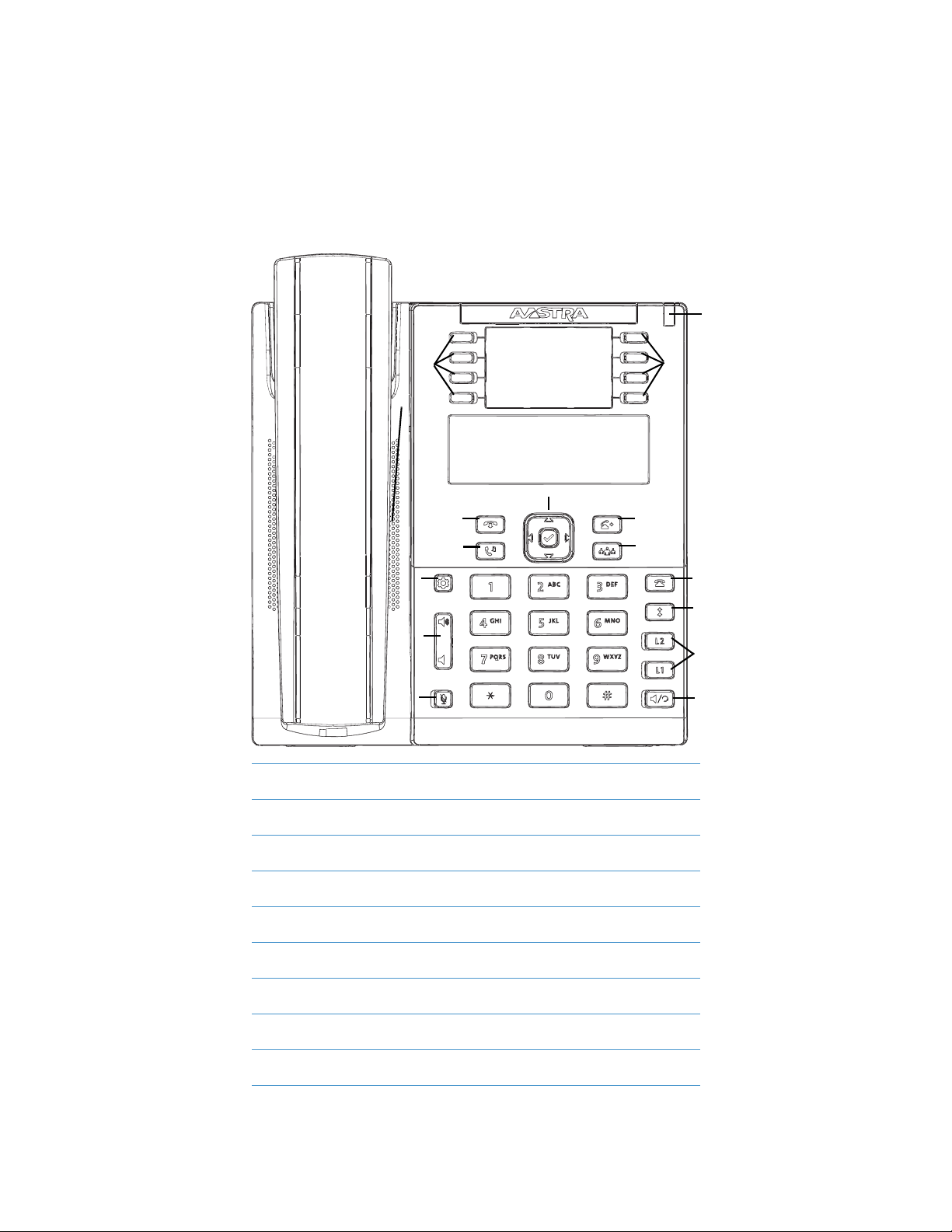
Key Panel
The following sections describe the various 6865i phone key functions and how they help you make and manage your
calls and caller information. Images of the symbol keys and the symbol hardware platform are used throughout this
document.
6865i Handset
High Quality Speakerphone
Message Waiting Lamp
Goodbye Key
Hold Key
Navigation/Select Keys
Transfer Key
Conference Key
Options Key
Volume Control
Mute Key
Keypad
Callers List Key
Redial Key
Line/Call Appearance Keys
Speaker/Headset Key
LCD Screen
Programmable Keys
41-001523-00 REV00 – 04.2014 3
Page 10
IP Phone Keys
Key Description
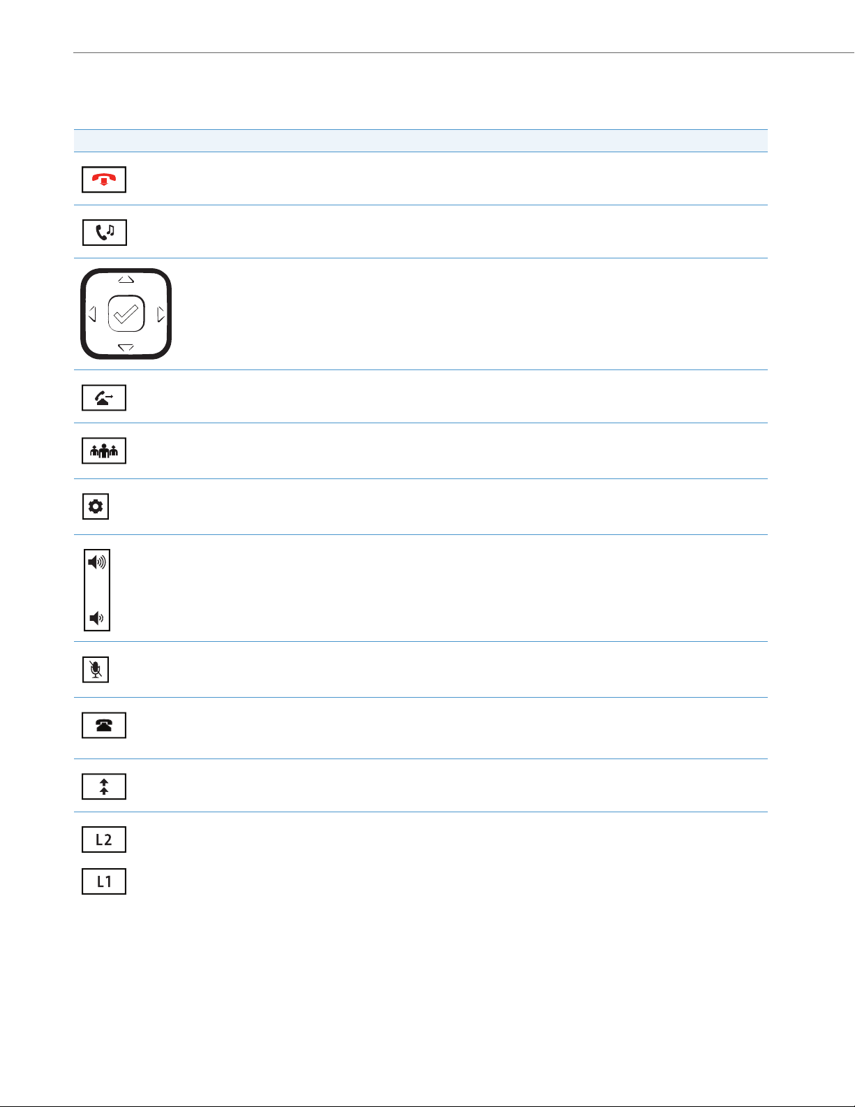
The following table identifies the keys on the key panel of your 6865i IP phone that you can use for handling calls.
Key Description
Goodbye Key - Ends an active call. The Goodbye key also exits an open list, such as the Options List, without saving changes.
Hold Key - Pl ac es a n ac tiv e ca ll o n h old . To re tri eve a h eld cal l, p ress the call appearance button beside the light that is flashing.
Navigation/Select Keys - Pressing the UP and DOWN keys lets you view different status and text messages on the LCD display
(if there is more than 1 line of status/text messages). These buttons also let you scroll through menu selections, such as the
Options List.
Pressing the LEFT and RIGHT keys lets you view the different line/call appearances. While in the Options List, these keys allow
you to exit or enter the current option. When you are editing entries on the display, pressing the LEFT key erases the character
on the left; pressing the RIGHT key sets the option. Alternatively, pressi ng the center Select k ey sets the option as well on specific screens.
Transfer Key - Transfers the active call to another number.
Conference Key - Begins a conference call with the active call.
Options Key - Accesses services and options to customize your phone. Your System Administrator may have already custom-
ized some of your settings. Check with your System Administrator before changing the administrator-only options.
Volume Controls - Adjusts the volume for the handset, ringer, and handsfree speaker.
Mute Key - Mutes the microphone so that your caller cannot hear you (the light indicator flashes when the microphone is on
mute).
Callers List Key - Accesses a list of the last 200 calls received.
Redial Key - Accesses a list of the last 100 previously dialed numbers. Pressing the Redial key twice redials the last dialed
number.
Line/Call Appearance Keys - Connects you to a line or call. The Aastra 6865i IP phone supports two line keys, each with LED
indicator lights.
4 41-001523-00 REV00 – 04.2014
Page 11
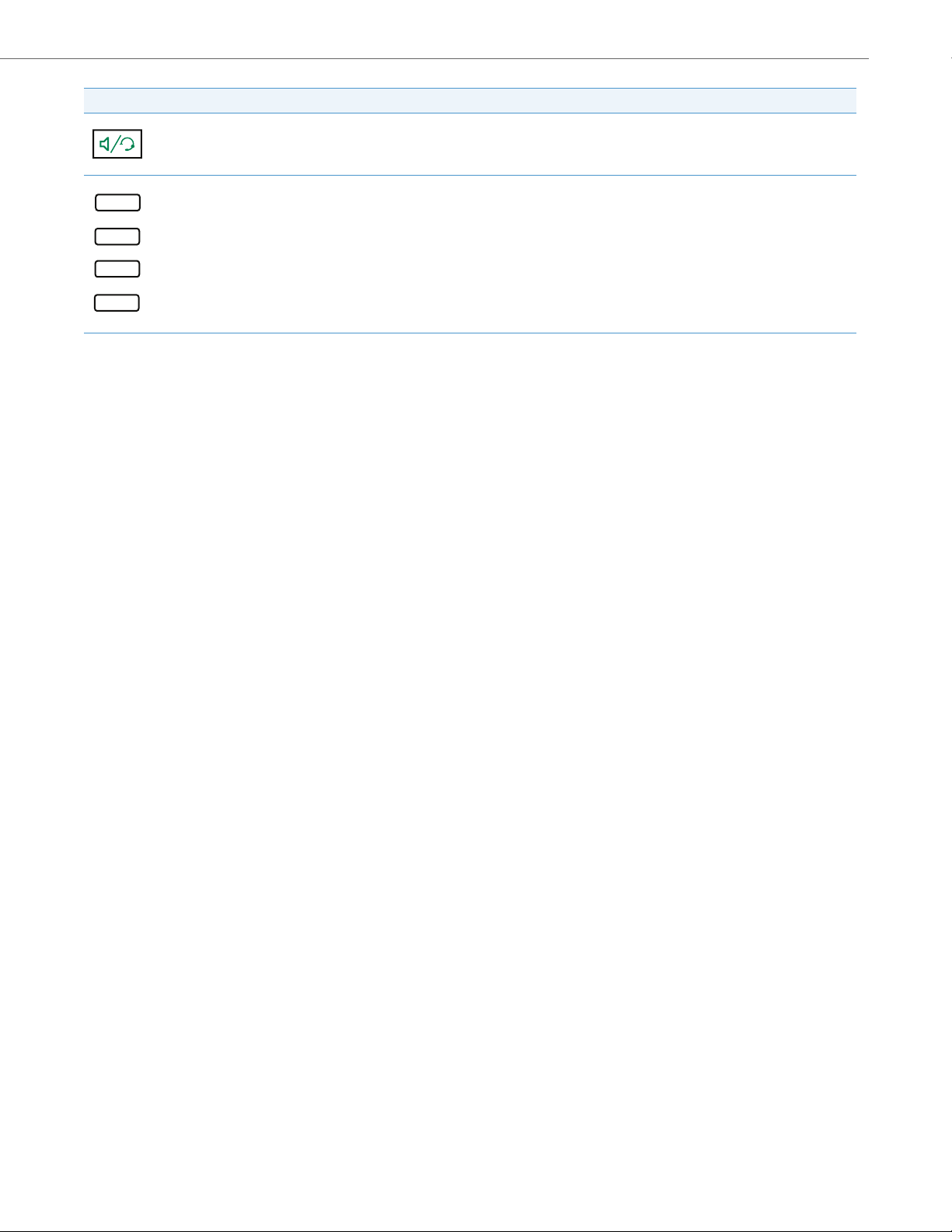
Key Description
Speaker/Headset Key - Transfers the active call to the speaker or headset, allowing handsfree use of the phone.
Programmable Keys - When programmed, allows you to easily perform up to 8 specific functions (e.g. Services, Directory,
Callers List, Intercom, etc...) and access enhanced services provided by third parties (e.g. XML applications).
IP Phone Keys
41-001523-00 REV00 – 04.2014 5
Page 12

IP Phone Keys
Keypad Keys
The 6865i has a keypad with digits from 0 through 9, a * key, and a # key. Keys 2 through 9 contain the letters of the
alphabet. The 6865i phone keypad includes the following:
Keypad Key Description
0Dials 0
1 Dials 1
2 ABC Dials 2
3 DEF Dials 3
4 GHI Dials 4
5 JKL Dials 5
6 MNO Dials 6
7 P QRS Dials 7
8 TUV Dials 8
9 WXYZ Dials 9
Dials the Operator on a registered phone
When entering text, this key enters A with one press, B with two presses, and C with three presses
When entering text, this key enters D with one press, E with two presses, and F with three presses
When entering text, this key enters G with one press, H with two presses, and I with three presses
When entering text, this key enters J with one press, K with two presses, and L with three presses
When entering text, this key enters M with one press, N with two presses, and O with three presses
When entering text, this key enters P with one press, Q with two presses, R with three presses, and S with four presses.
When entering text, this key enters T with one press, U with two presses, and V with three presses
When entering text, this key enters W with one press, X with two presses, Y with three presses, and Z with four presses.
The * is called the star key. The # is called the number sign, pound key, or hash key, depending on one's nationality or
personal preference. These can be used for special functions such as accessing voicemail. The star key and pound key
functions are dependant on your country’s feature availability. Contact your System Administrator for more information
about available functions using these keys.
These keypad keys can be used for any of the following on the phone:
• Dialing a phone number to make a call (see “Dialing a Number” on page 97).
• Entering digits or letters in the IP phone user interface.
• Programming a speed dial number (see “Creating a Speed Dial Key” on page 46).
• Pressing a speed dial key (see “Creating a Speed Dial Key” on page 46).
• Pressing the keys associated with a called Interactive Voice Response (IVR) system.
6 41-001523-00 REV00 – 04.2014
Page 13
Getting Started
Aastra 6865i
LLDP
Aastra 6865i
DHCP
The 6865i must be set up and configured prior to its first use. This section describes phone behavior and start up screens
you may see when the phone is first plugged in, or when it is restarted.
Plugging in and Starting the Phone
The 6865i automatically begins the start up sequence as soon as it is connected. The phone goes through this process the
first time you plug in your phone and every time you restart your phone.
Note:
Some start up screens only appear the first time you connect your phone, or if your phone has been factory defaulted.
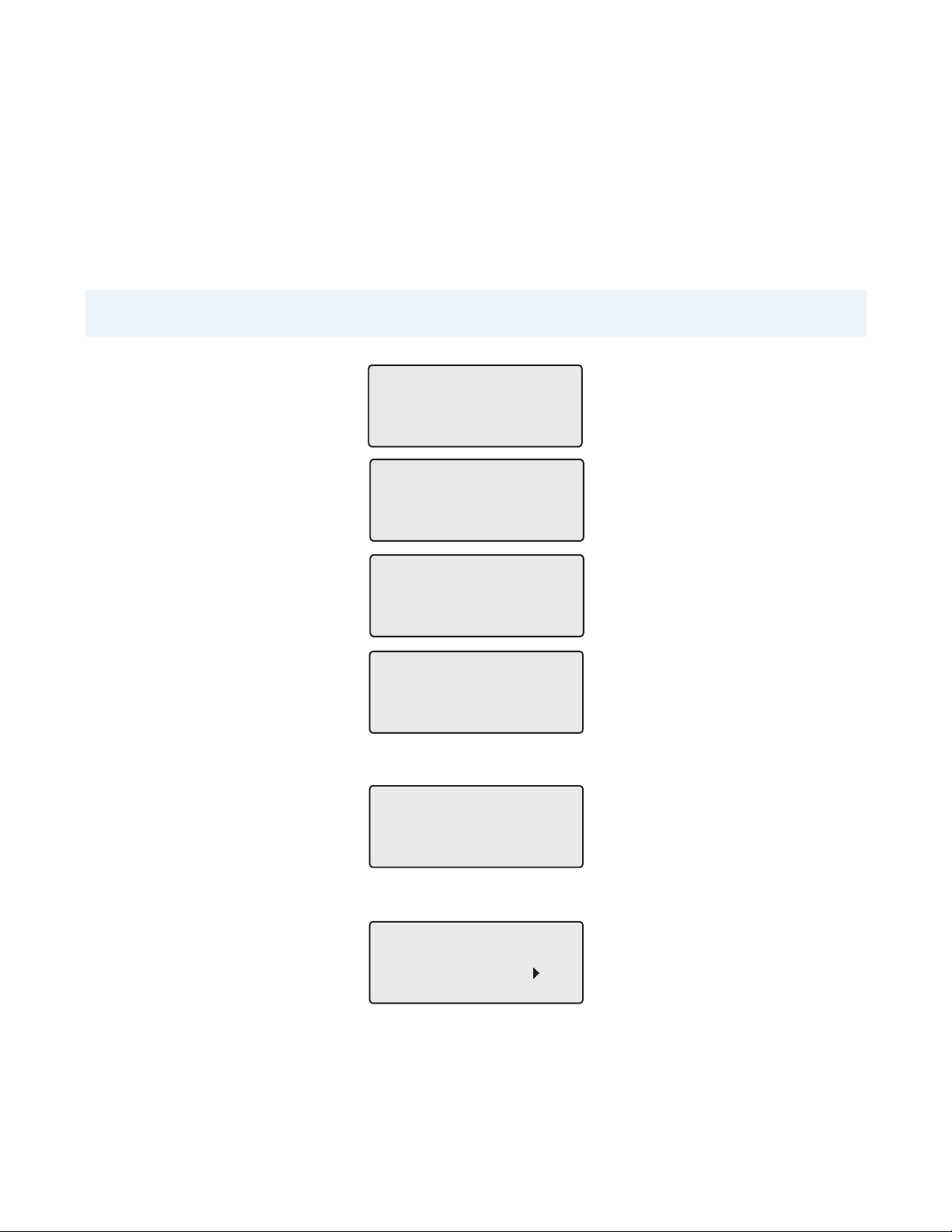
The phone displays the following startup screens:
Aastra 6865i
Initializing
network
During the first start up, the 6865i phone attempts to contact the Redirection and Configuration Server (rcs.aastra.com)
for current server information. No personal information is transmitted from the phone during this process.
Contacting
Redirector
The 6865i phone may also look for configuration servers on your local network (press 4Skip to continue without checking for servers).
Auto Discovery
Skip
41-001523-00 REV00 – 04.2014 7
Page 14
Getting Started
Network
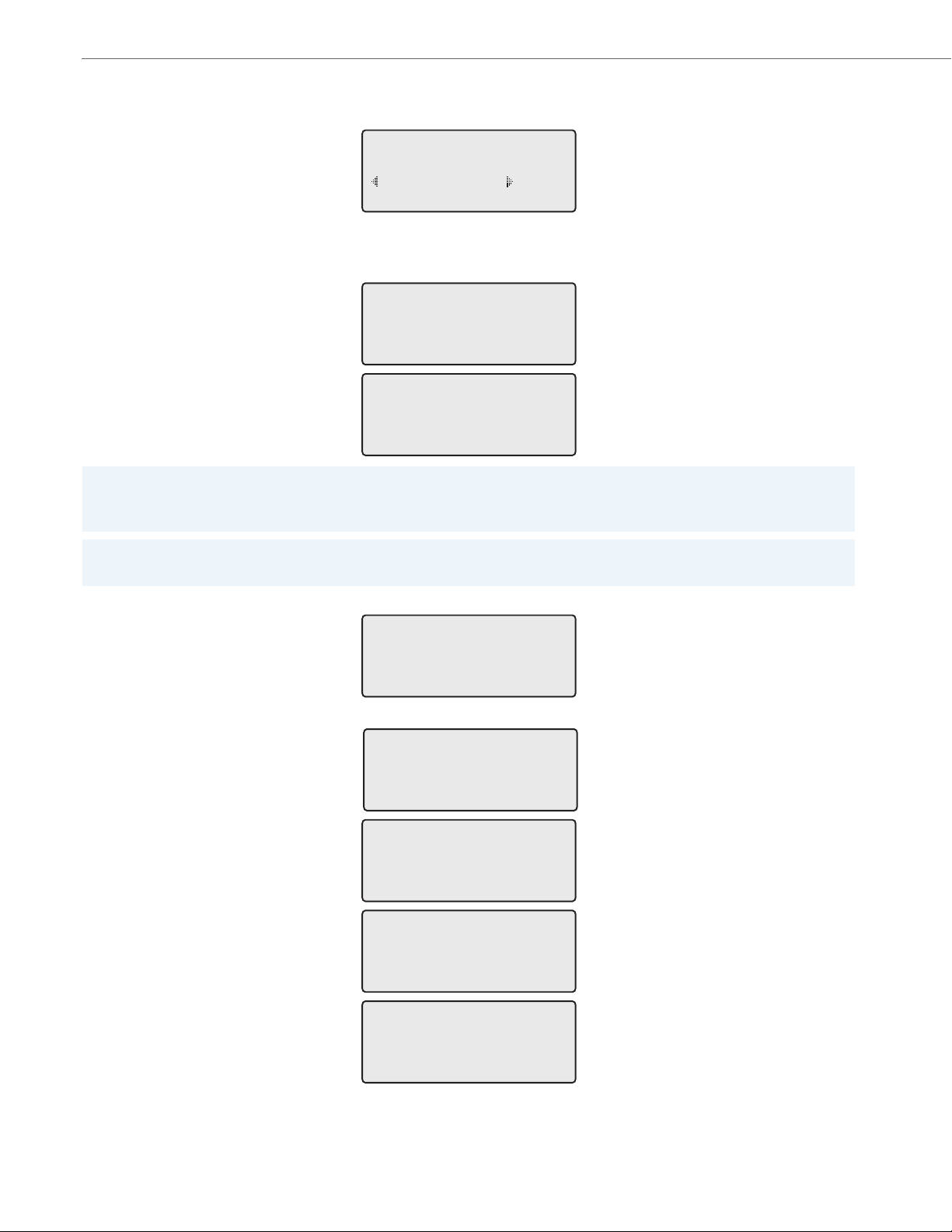
If appropriate servers are found they are listed for you to select from by scrolling down to view the complete list. (Press
3Skip to continue without selecting a server.).
1 Choose Server
<Server Name>
Skip Select
The 6865i phone then checks settings and looks for new configuration and firmware updates from a server. If a new
update is found, the phone displays the message Updating Configuration. This may take a few moments while the
phone downloads the latest updates.
Updating
configuration
Checking for new
firmware
Note:
New updates to your phone can be automatically scheduled from the server. This is set up on the phone system by your
System Administrator and should be scheduled during non-business hours or slow call periods.
Important!
Do not unplug or remove power to the phone while it is checking or installing firmware and configuration information.
If language packs were loaded to your phone by your System Administrator, the following screen displays during startup.
Downloading
Language Packs
When the configuration update is complete, the phone displays the following screens:
DSP
SIP
Done
8 41-001523-00 REV00 – 04.2014
Page 15
Getting Started
John Smith
9055550055
Tue Aug 20 2:55pm
L1
John Smith
CFWD All
Tue Aug 20 2:55pm
L1
Network Connected
L1
Idle Screens
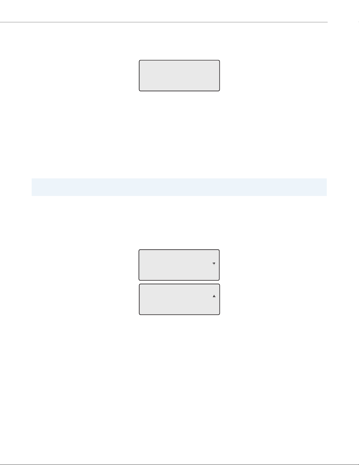
When the phone has successfully updated the configuration and connected to the network, the phone displays the Idle
State screen:
The Idle State screen lists your name (SIP screen name), extension (or phone number), and the date and time. This screen
is shown whenever your phone is not in use. The L1 in the upper corner in the above example indicates the idle screen for
the first line appearance. You can use the left and right arrow keys to scroll through the idle screens for both line appearances on the 6865i.
The second display line shows the following temporary messages if the event occurs:
• No Service
• DHCP Failed
• Restarting
• New IP Obtained
• Network Disconnected/Connected
Note:
Since Network Disconnected/Connected displays on two lines, the date and time does not show if this event displays.
• The second line can also display the following status messages, listed in order of display priority:
• Call Forward status
• DND (Do Not Disturb) On
• Number of missed calls
When more than one status message displays, the 2 is shown after the message to indicate that you can use the 2 and 5
navigation keys to scroll through the remaining messages.
41-001523-00 REV00 – 04.2014 9
Page 16

Getting Started
Incomplete Configuration
If your phone displays an Incomplete Config message without any extension or user name at the end of the start up
sequence instead of an Idle state screen, this indicates the phone configuration that was downloaded from the configuration server is not complete or correct. Contact your System Administrator for assistance.
No Service
When the phone is not properly connected to the network, or the account has not been configured by the Network
Administrator, the No Service or Network Disconnected prompt appears on the display and the telephone status light
turns ON. Check that the cables are tightly connected to the phone and to the wall jack. The phone should automatically
detect when the connection is reconnected and display the Network Connected prompt temporarily.
If changes have been made to your phone settings, you may need to restart your phone. For more information on
restarting your phone, see “Restarting Your Phone” on page 39.
For more information about connecting your phone, refer to the Aastra 6865i Installation Guide or check with your Sys-
tem Administrator for assistance.
10 41-001523-00 REV00 – 04.2014
Page 17

Methods for Customizing Your Phone
There are two ways to customize specific options on your phone:
• Using the Options key on the IP phone.
• Using the Aastra Web UI in an Internet browser window from your PC.
Phone Options via the IP Phone UI
You can customize your phone by pressing the key and accessing the IP phone UI. These options allow you to customize the following phone settings.
Option Number Option
1Call Forward
1. All
2. Busy
3. No Answer
4. All Off
5. All On
The menus that display for Call Forward are dependant on the Call Forward Mode set on the phone. Default is Account mode.
2Preferences
3 Phone Status
4Password
5 Admin Menu (Password Protected)*
6Restart Phone
7 Phone Lock
1. To ne s
– Ring Tone
– Ton e Se t
2. Display
– Contrast Level
– Backlight
3. Speed Dial Edit
4. Live Dialpad
5. Set Audio
– Audio Mode
– Headset Mic Vol
– DHSG
6. Time and Date
– Time Format
– Daylight Savings
– Date Format
– Time Zone
– Time Server 1
– Time Server 2
– Time Server 3
– Set Time
– Set Date
7. Language
– Screen Language
– Input Language
1. IP&MAC Addresses
2. LAN Port
3. PC Port
4. Firmware Info
5. Error Messages
6. Copyright
41-001523-00 REV00 – 04.2014 11
Page 18
Methods for Customizing Your Phone
Note:
*The Administrator Menu options are Administrator-level functions only, and are not accessible by the user. These
options should only be set up and changed by your System Administrator.
Simplified Options List
Your System Administrator may configure a simplified Options List for your phone. The following table indicates the
options that may appear on your phone if the simplified Options List is applied:
Option Number Option
1Call Forward
2Preferences
3 Phone Status
4 Phone Lock
1. All
2. Busy
3. No Ans
4. All Off
5. All On
The menus that display for Call Forward are dependent on the Call Forward Mode set on the phone. Default is Account mode.
1. To ne s
– Ring Tone
– Ton e Set
2. Display
– Contrast Level
– Backlight
3. Set Audio
– Audio Mode
– Headset Mic Vol
– DHSG
1. IP&MAC Addresses
2. LAN Port
3. PC Port
4. Firmware Info
5. Error Messages
6. Restart Phone
7. Copyright
Using the IP Phone UI
IP Phone UI
1. Press the key on the phone to enter the Options List.
2. Press the 5 and 2 keys to view the different options.
3. Press the key, the 4 Enter key, or press the number of the corresponding option to select an option.
4. Change the selected option if required.
5. Press the key or the 4Set, or 4Done key to save the change.
6. Press the key, the 3 navigation key, or the key at any time to exit without saving changes.
Note:
For more information about customizing your phone using the available options from the IP phone UI, see the section
“Customizing Your Phone” on page 19. For more information about Administrator options, contact your System
Administrator.
12 41-001523-00 REV00 – 04.2014
Page 19
Methods for Customizing Your Phone
Phone Options via the Aastra Web UI
In addition to the IP phone UI options, you can customize additional options on the IP phone using the Aastra Web UI. In
order to access your phone using the Aastra Web UI, you need to know your phone’s IP address. To find your phone’s IP
address, see “Finding Your Phone’s IP Address” on page 16.
Using the Aastra Web UI
Aastra Web UI
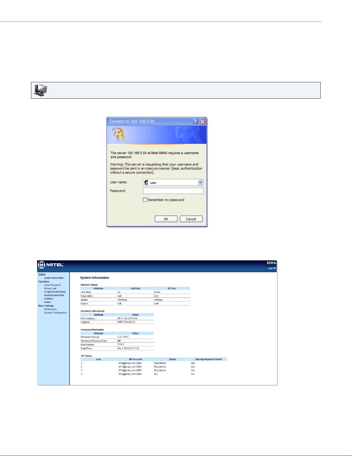
1. Open your web browser, enter the phone’s IP address or host name into the address field and press Enter.
The following logon screen displays:
2. At the prompt, enter your username and password and click OK.
The Status window displays for the IP phone you are accessing.
Note:
For a user, the default username is user and the password field is left blank.
3. You can logout of the Aastra Web UI at any time by clicking Log Off.
41-001523-00 REV00 – 04.2014 13
Page 20

Methods for Customizing Your Phone
• None • BLF/Xfer
• Line • Speeddial/Xfer
• Speeddial • Speeddial/Conf
• Do Not Disturb (DND) • Directory
• BLF (Busy Lamp Field) • Callers List
• BLF/List • Redial
• Auto Call Distribution (ACD) • Conference
• XML (Extensible Markup Language) • Trans fer
• Flash • Icom (Intercom)
• Sprecode • Services
• Park • Phone Lock
• Pickup • Paging
• Last Call Return (LCR) • Save
• Call Fwd (Call Forward) • Delete
The following categories display in the side menu of the Aastra Web UI: Status, Operation, and Basic Settings.
Headings Descriptions
Status The Status section displays the network status and the MAC address of the IP phone. I t also displays hardware and firmware informa-
Operation User Password - Allows you to change the user password.
tion regarding the IP phone, and information about the SIP account(s) currently configured on the phone. The information in the Sta-
tus window is read-only.
Phone Lock - Allows you to assign an emergency dial plan to the phone, lock the phone to prevent any changes to the phone and to
prevent use of the phone, as well as reset the user password.
Programmable Keys - Allows you to configure up to 8 programmable keys with functions identified in the list below.
Keypad Speed Dial - Allows you to assign a speed dial number to a specific digit on the phone’s keypad/dialpad for speed dialing pur-
poses.
Expansion Module - Allows you to configure an additional 16 softkeys with a M680i Expansion Module if it is attached to the phone.
This option displays on the side menu of the Aastra Web UI only if an Expansion Module is attached. Not all functions in the table above
apply to the expansion modules.
Directory - Allows you to copy the Callers List and Directory from your IP phone to your PC.
Reset - Allows you to restart the IP phone when required.
Basic Settings Preferences - Allows you to enable/disable the following:
• Display DTMF Digits
• Play Call Waiting Tone
• Stuttered Dial Tone
• XML Beep Support
• Status Scroll Delay (seconds)
• Switch UI Focus to Ringing Line
• Call Hold Reminder During Active Calls
• Call Hold Reminder
• Call Waiting Tone Period
• Preferred Line
14 41-001523-00 REV00 – 04.2014
• Preferred Line Timeout (seconds)
• Goodbye Key Cancels Incoming Call
• Message Waiting Indicator Line
• DND Key Mode
• Call Forward Key Mode
This category also allows you to configure:
• Incoming Intercom Call Settings
• Group Paging RTP Settings
• Ring Tones (global and per-line basis)
• Time and Date Settings
• Language Settings
Account Configuration - Allows you to configure DND and Call Forward by account. You can have multiple accounts on the 6865i.
Page 21
Phone Status
You can view the status of your phone using the IP phone UI or the Aastra Web UI.
Phone Status via IP Phone UI
The Phone Status option on the IP phone displays the status of your phone to the LCD display.
This option allows you to view your phone’s:
• Network status including your phone’s IP and MAC addresses
• Local Area Network (LAN) port information
• PC Port information (if PC link exists)
• Firmware information
• Error messages from the last reboot or startup
• Copyright information
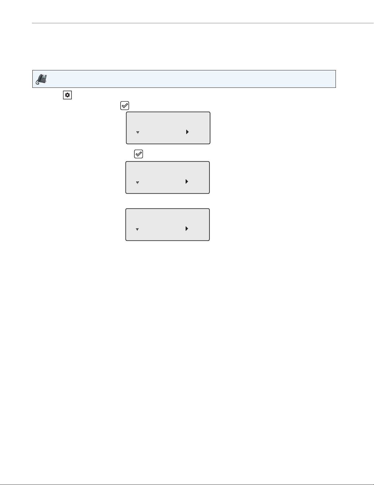
IP Phone UI
1. Press on the phone to enter the Options List.
2. Select Phone Status.
3. Select the option you want to view:
• IP&MAC Address
• LAN Port
• PC Port
• Firmware Info
• Error Messages
• Copyright
The option you select displays to the screen. Use the 2 and 5 keys to scroll the through the content displayed on
screen.
41-001523-00 REV00 – 04.2014 15
Page 22
Phone Status
Phone Status
Next Enter
3
IP&MAC Addresses
Next Enter
1
IP Address
10.40.50.112
Next Enter
Finding Your Phone’s IP Address
If you want to access your phone’s options using an Internet browser, you need to enter the IP address of the phone in
the browser to open the Aastra Web UI. Use the following procedure to find your phone’s IP address.
IP Phone UI
1. Press the key on the phone to enter the Option List.
2. Select Phone Status and press the key or 4 Enter key.
3. Select IP&MAC Addresses and press the key or 4 Enter key.
The IP address of your 6865i IP phone displays in the IP Address field.
16 41-001523-00 REV00 – 04.2014
Page 23
Phone Status via the Aastra Web UI
Use the following procedure to view the phone status via the Aastra Web UI.
Aastra Web UI
1. Open your web browser, enter the phone’s IP address or host name into the address field and press Enter.
2. In the Username/Password window, enter your username and password and click OK.
The Status window displays for the IP phone you are accessing.
Note:
The default username is user and the password field is left blank.
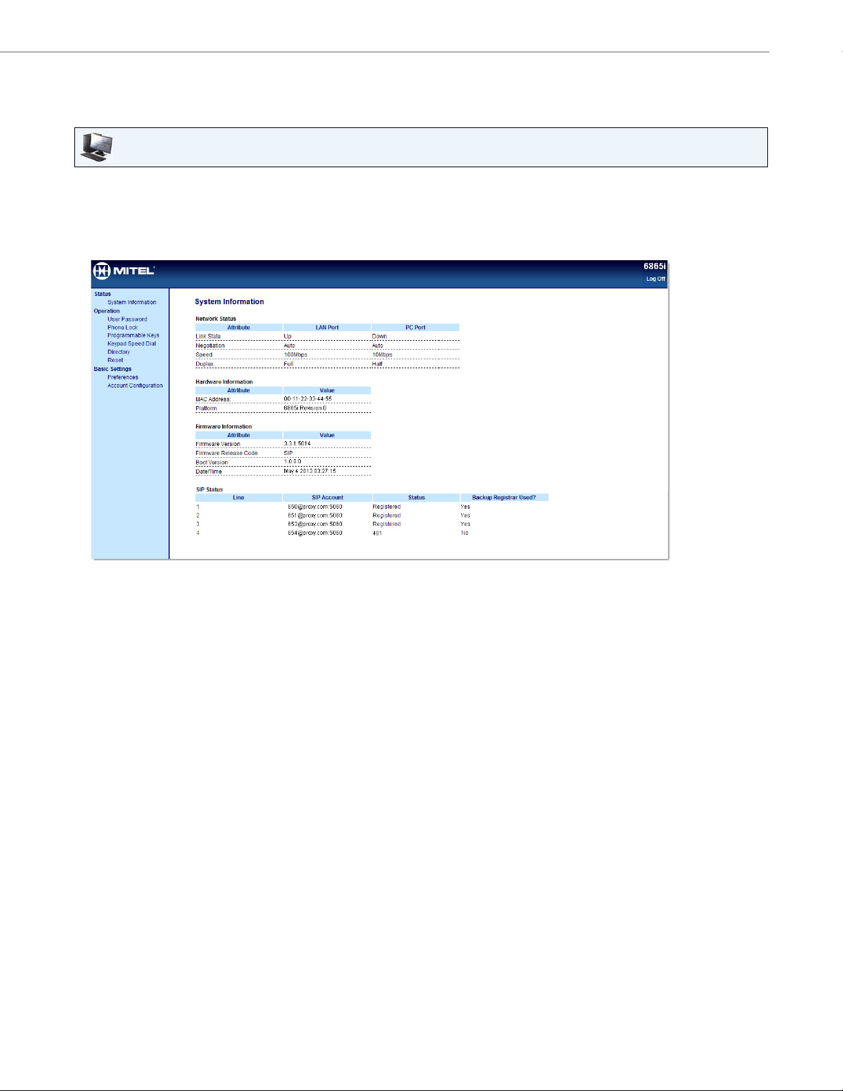
Phone Status
This Status window displays the status of your phone, which includes the following information:
• Network Status
• Hardware Information
• Firmware Information
• SIP Status
41-001523-00 REV00 – 04.2014 17
Page 24
Phone Status
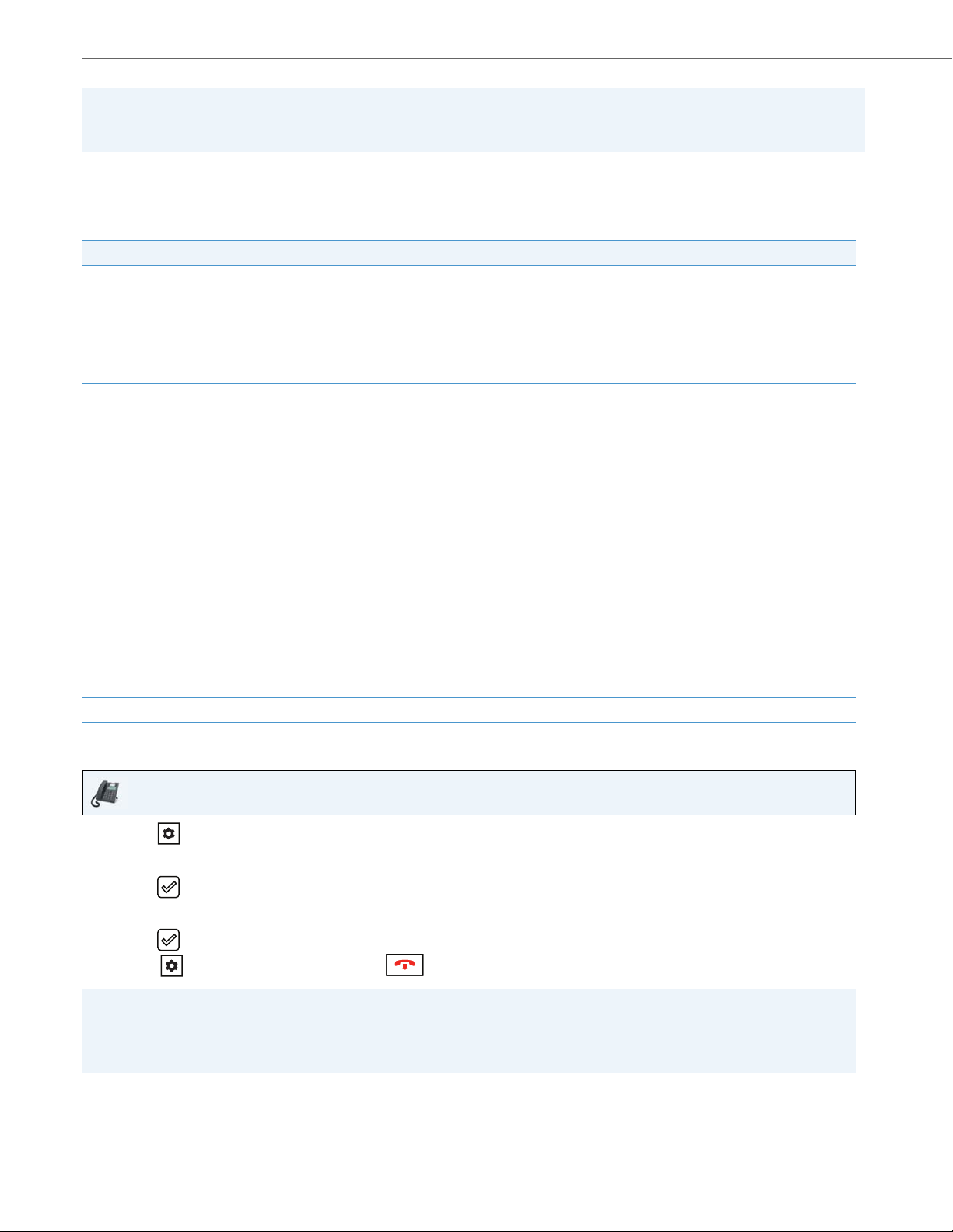
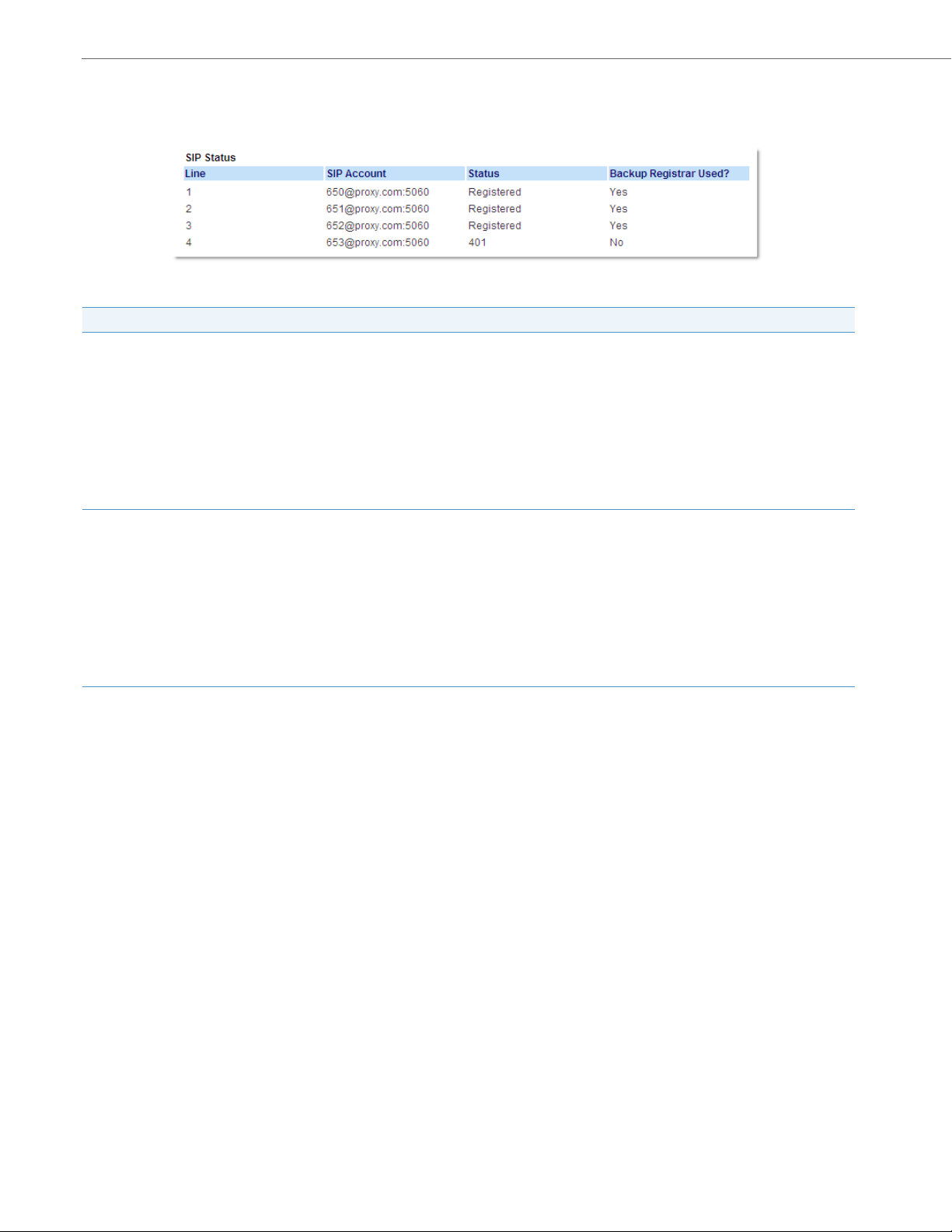
SIP Account Status
The IP phones show the SIP registration status on the IP phone’s Status screen in the Aastra Web UI.
The following table describes the status conditions that can display for the account.
Status Condition Description
Registered Displays this status on accounts that HAVE been registered with the SIP proxy server.
Example:
Line SIP Account Status Backup Registrar Used?
1 650@proxy.com:5060 Registered Yes
where:
• Account Number is 1
• SIP Account is 650@proxy.com on port 5060
• Status is Registered
• Backup registrar is used (Yes)
SIP Error Number Displays on accounts when registration fails with the SIP proxy server.
Example:
Line SIP Account Status Backup Registrar Used?
4 653@proxy.com:5060 401 No
where:
• Account Number is 4
• SIP Account is 653@proxy.com on port 5060
• Status is 401 - Unregistered if SIP registration fails
• Backup registrar is used (No)
18 41-001523-00 REV00 – 04.2014
Page 25

Customizing Your Phone
The following paragraphs describe the options available from either the IP phone UI, the Aastra Web UI, or both, and provide procedures applicable to the option.
Ring Tones and Tone Sets
You can configure ring tones and ring tone sets on the IP phone.
Ring Tones
There are several distinct ring tones a user can select from to set on the IP phones. You can enable/disable these ring tones
on a global or per-line basis.
The following table identifies the valid settings and default values for each type of configuration method:
Ring Tones
Configuration Method Valid Values Default Value
IP Phone UI Global
Ton e 1
Ton e 2
Ton e 3
Ton e 4
Ton e 5
Silent
Aastra Web UI Global:
Ton e 1
Ton e 2
Ton e 3
Ton e 4
Ton e 5
Silent
Lines 1 through 9 Per-Line Setting:
Global
Ton e 1
Ton e 2
Ton e 3
Ton e 4
Ton e 5
Silent
Global Setting:
Ton e 1
Global Setting:
Ton e 1
Per-Line Setting:
Global
41-001523-00 REV00 – 04.2014 19
Page 26
Customizing Your Phone
Ring Tone Sets
In addition to ring tones, you can configure ring tone sets on a global-basis on the IP phone. Ring tone sets consist of
tones customized for a specific country. The ring tone sets you can configure on the IP phones are:
• Australia
• Brazil
• Europe (generic tones)
• France
• Germany
• Italy
• Italy2
• Malaysia
• Mexico
• Russia
• Slovakia
• UK
• US (Default - also used in Canada)
When you configure the country's tone set, the country-specific tone is heard on the phone for the following:
• Dial tone
• Secondary dial tone
• Ring tone
• Busy tone
• Congestion tones
• Call waiting tone
• Ring cadence pattern
You configure global ring tones and tone sets using the Aastra Web UI and the IP phone UI.
Configuring Ring Tones and Tone Sets
IP Phone UI
Global configuration only
1. Press on the phone to enter the Options List.
2. Select Preferences.
3. Select To n es .
4. Select Ring Tone.
5. Select the type of ring tone (Ton e 1 through Tone 5, or Silent).
6. Press the key or select 4Set .
7. Select Tone S et.
20 41-001523-00 REV00 – 04.2014
Page 27
8. Select the country for which you want to apply the tone set. Valid values are:
• Australia
• Brazil
• Europe
• France
• Germany
• Italy
• Italy2
• Malaysia
• Mexico
• Brazil
• Russia
• Slovakia
• UK
• US (default)
9. Press the key or select 4Set.
The ring tone and tone set you select is immediately applied to the IP phone.
Aastra Web UI
Customizing Your Phone
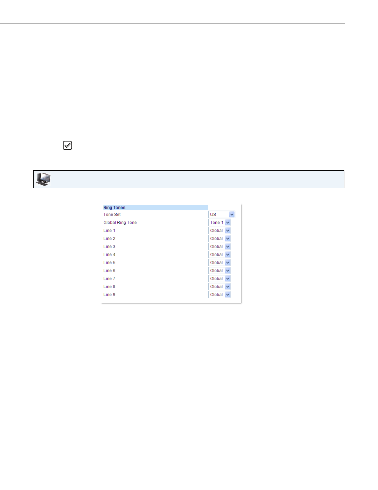
1. Click on Basic Settings > Preferences > Ring Tones.
For global configuration
2. In the Ring Tones section, select a country from the Ton e Set field. Valid values are:
• Australia
• Brazil
• Europe
• France
• Germany
• Italy
• Italy2
• Malaysia
• Mexico
• Brazil
• Russia
• Slovakia
• UK
• US (default)
41-001523-00 REV00 – 04.2014 21
Page 28
Customizing Your Phone
3. Select a value from the Global Ring Tone field.
Note:
See the “Ring Tones” on page 19 for valid values.
For per-line configuration
4. In the Ring Tone section, select a line for which you want to set ring tone.
5. Select a value from the LineN field.
Note:
See the “Ring Tones” on page 19 for valid values.
6. Click Save Settings.
Display
The 6865i IP phone allows you to configure display settings pertaining to the LCD contrast level and backlight.
Contrast Level
The Contrast Level option on the IP phone allows you to set the amount of contrast on the LCD display. You can set the
contrast level using the IP phone UI only.
Setting the Contrast Level
IP Phone UI
1. Press on the phone to enter the Options List.
2. Select Preferences.
3. Select Display.
4. Select Contrast Level.
5. Use the 3 and 4
6. Press the key or 4Select to save your selection.
navigation keys to increase or decrease the amount of contrast on the screen.
Backlight
The Backlight option on the IP phone allows you to set the backlight status on the LCD display to the following:
• Off: Backlight is always off.
• Auto (default): Automatically turns on the backlight when the phone is in use, and then automatically turns off the
backlight when the phone is idle after a specified length of time.
22 41-001523-00 REV00 – 04.2014
Page 29
Customizing Your Phone
Configuring Backlight Options
IP Phone UI
1. Press on the phone to enter the Options List.
2. Select Preferences.
3. Select Display.
4. Select Backlight.
5. Use the 5 or 2 navigation keys to navigate to Off or Auto.
6. Press the key or select 4Set to save your selection.
Live Dialpad*
The Live Dialpad option on the IP phone turns the live dialpad mode on or off. With the live dialpad feature enabled, the
6865i IP phone automatically dials out and turns on handsfree mode as soon as a dialpad/keypad key or programmable
key is pressed. With live dialpad disabled, if you dial a number while the phone is on-hook, lifting the receiver or pressing
the initiates a call to that number.
Note:
Availability of this feature is dependant on your phone system or service provider.
You can enable/disable the live dialpad using the IP phone UI only.
Enabling/Disabling Live Dialpad
IP Phone UI
1. Press on the phone to enter the Options List.
2. Select Preferences.
3. Select Live Dialpad.
4. Use the 5 and 2
5. Press the key or select 4Set to save your selection.
navigation keys to navigate to ON or OFF.
41-001523-00 REV00 – 04.2014 23
Page 30
Customizing Your Phone
Set Audio
The Set Audio option on the IP phone allows you to set the audio mode for your IP phone. It also allows you to set the
volume level of the headset microphone and enable/disable DHSG. You can configure audio options on your IP phone
using the IP phone UI only.
Audio Mode
The 6865i allows you to use a handset, a headset, or handsfree mode to handle incoming and outgoing calls. The Audio
Mode option provides different combinations of these three methods to provide maximum flexibility in handling calls.
There are four audio mode options you can set:
Audio Mode Option Description
Speaker This is the default setting. Calls can be made or received using the handset or handsfree speakerphone. In handset
audio mode, pressing the button on the phone switches to handsfree speakerphone. In Speaker audio
mode, lift the handset to switch to the handset.
Headset Ch oos e th is s et tin g if you wan t to mak e or rec eiv e al l ca lls usi ng a ha nds et o r he ads et. Cal ls c an b e sw itc he d fro m t he
handset to headset by pressing the button on the phone. To switch from the headset to the handset, lift the
handset.
Speaker/Headset
Headset/Speaker
Incoming calls are sent to the handsfree speakerphone first when the button is pressed. By pressing the
button again, you can switch back and forth between the handsfree speakerphone and the headset. At anytime, lift-
ing the handset switches back to the handset from either the handsfree speakerphone or the headset.
Incoming calls are sent to the headset first when the button is pressed. By pressing the button again, you
can switch back and forth between the headset and the handsfree speakerphone. At anytime, lifting the handset
switches back to the handset from either the headset or the handsfree speakerphone.
Setting Audio Mode
IP Phone UI
1. Press on the phone to enter the Options List.
2. Select Preferences.
3. Select Set Audio.
4. Select Audio Mode.
5. Select the audio mode you want to use on your phone. Valid values are:
• Speaker (Default)
• Headset
• Speaker/Headset
• Headset/Speaker
6. Press the key or select 4Set to save your selection.
24 41-001523-00 REV00 – 04.2014
Page 31

Customizing Your Phone
Headset Mic Volume
The Headset Mic Volume option allows you to set the volume level for the headset microphone.
Setting Headset Mic Volume
IP Phone UI
1. Press on the phone to enter the Options List.
2. Select Preferences.
3. Select Set Audio.
4. Select Headset Mic Volume.
5. Select the Low, Medium, or High volume level. Default is Medium.
6. Press the key or select 4Set to save your selection.
DHSG
The DHSG option allows you to enable or disable DHSG headset support.
Note:
A DHSG headset and an expansion module cannot be used concurrently as they both share the same headset port.
Enabling/Disabling DHSG
IP Phone UI
1. Press on the phone to enter the Options List.
2. Select Preferences.
3. Select Set Audio.
4. Select DHSG.
5. Select the DHSG is OFF or DHSG is ON option. Default is DHSG is OFF.
6. Press the key or select 4Set to save your selection.
41-001523-00 REV00 – 04.2014 25
Page 32

Customizing Your Phone
Time and Date
On the IP phones, you can configure the following:
• Time and date
• Time and date format
• Time zone
• Daylight savings time
• Time servers
Note:
Only the time and date formats and time servers can be set using the Aastra Web UI
Configuring Time and Time Format
IP Phone UI
1. Press on the phone to enter the Options List.
2. Select Preferences.
3. Select Time and Date.
4. Select Set Time.
5. Using the keys on the keypad, enter a time to set on the IP phone. Use the * key to set either AM or PM.
6. Press the key or select 2Done to save the time setting.
7. Select Time Format.
8. Using the 5 and 2
is 12 Hour.
9. Press the key or select 4Set to save the Time Format you selected.
navigation keys, set the Time Format to either a 12 hour format or a 24 hour format. Default
26 41-001523-00 REV00 – 04.2014
Page 33

Configuring Date and Date Format
IP Phone UI
1. Press on the phone to enter the Options List.
2. Select Preferences.
3. Select Time and Date.
4. Select Set Date.
5. Using the keys on the keypad, enter a date to set on the IP phone.
6. Press the key or select 2 Done to save the date setting.
7. Select Date Format.
8. Select a date format from the list of options. Valid values are:
• WWW MMM DD (default)
• DD-MMM-YY
• YYYY-MM-DD
• DD/MM/YYYY
• DD/MM/YY
• DD-MM-YY
• MM/DD/YY
• MMM DD
• DD MMM YYYY
• WWW DD MMM
• DD MMM
• DD.MM.YYYY
Customizing Your Phone
9. Press the key or select 4Set to save the Date Format setting.
Configuring the Time Zone
IP Phone UI
1. Press on the phone to enter the Options List.
2. Select Preferences.
3. Select Time and Date.
4. Select Time Zone.
A list of Time Zones display for different areas of the world.
5. Select a Time Zone that applies to your area by using the navigation keys.
The default Time Zone is US-Eastern.
Note:
For a list of the Time Zone values available on the IP phone, see “Appendix A - Time Zone Codes.”
6. Press the key or select 4Set to save the Time Zone setting.
G5
41-001523-00 REV00 – 04.2014 27
Page 34

Customizing Your Phone
Configuring Daylight Savings Time
IP Phone UI
1. Press on the phone to enter the Options List.
2. Select Preferences.
3. Select Time and Date.
4. Select Daylight Savings.
5. Select a Daylight Savings time from the list of options.
Valid values are:
• OFF
• 30 min summertime
• 1 h summertime
• Automatic (Default)
6. Press the key or select 4Set to save the Daylight Savings setting.
Configuring Time Servers
With a valid time server enabled your IP phone will synchronize the time displayed with the specified configuration
server. The phone will use the time from Time Server 1 unless it is not configured or unavailable, in which case it will
move on to Time Server 2, and if necessary Time Server 3
.
IP Phone UI
1. Press on the phone to enter the Options List.
2. Select Preferences.
3. Select Time and Date.
4. Select from Time Server 1, Time Server 2, or Time Server 3.
5. Enter an IP address or domain name for the time server.
Note:
Time Servers are enabled by default. The Time Servers can be Enabled or Disabled only from the Aastra Web UI.
6. Press the key or select 4Set to save the time server setting.
28 41-001523-00 REV00 – 04.2014
Page 35

Aastra Web UI
1. Click on Basic Settings > Preferences > Time and Date Setting
2. In the Time Format field, select the time format you want to use on your phone. Valid values are:
• 12h (12 hour format) (default)
• 24h (24 hour format)
Note:
The time and time format you configure display on the phone’s idle screen.
3. In the Date Format field, select the date format you want to use on your phone. Valid values are:
• WWW MMM DD (default)
• DD-MMM-YY
• YYYY-MM-DD
• DD/MM/YYYY
• DD/MM/YY
• DD-MM-YY
• MM/DD/YY
• MMM DD
• DD MMM YYYY
• WWW DD MMM
• DD MMM
• DD.MM.YYYY
Note:
The date and date format you configure display on the phone’s idle screen.
Customizing Your Phone
4. In the NTP Time Servers field, enable by checking the checkbox or disable by unchecking the box (default is enabled).
5. In the Time Server 1, Time Server 2, and Time Server 3 fields, enter IP addresses or qualified domain names for the
primary, secondary, and tertiary time servers.
Note:
Time Servers can only be entered if NTP Time Servers is enabled.
6. Click Save Settings.
41-001523-00 REV00 – 04.2014 29
Page 36

Customizing Your Phone
Language
The IP phones support several different languages. You can have the IP phone UI and the Aastra Web UI display in a specific language as required. When you set the language to use, all of the display screens (menus, services, options, configuration parameters, etc.) display in that language. The IP phones support the following languages:
• English
• Czech
• Catalan
• Valencian
• Welsh
• German
• Danish
• Spanish
• Mexican Spanish
• Finnish
• French
• Canadian French
• Italian
• Dutch
• Dutch (Netherlands)
• Norwegian
• Polish
• Portuguese
• Portuguese Brazilian
• Romanian
• Russian
• Slovak
• Swedish
• Turkis h
You can also configure the language to use when inputting values in the Aastra Web UI and the IP phone UI.
Specifying the Language to Use
Once the language pack(s) are available on your phone from your System Administrator, you can specify which language
to use on the phone and/or the Aastra Web UI.
Note:
All languages may not be available for selection. The available languages are dependant on the language packs currently loaded to the IP phone.
30 41-001523-00 REV00 – 04.2014
Page 37

Customizing Your Phone
IP Phone UI
1. Press on the phone to enter Options List.
2. Select Preferences.
3. Select Language.
4. Select Screen Language.
The language setting displays a check mark indicating this is the current language on the IP phone.
5. Using the 2 and 5 keys, scroll through the languages.
Note:
All languages may not be available for selection. The available languages are dependant on the language packs
currently loaded to the IP phone. English is the default language and cannot be changed or removed. For more
information about loading language packs, see your System Administrator.
6. Press the key or select 4Set to set the language on the phone.
The change is dynamic. When you exit the Options List, the phone displays all menu items in the language you
selected.
Aastra Web UI
1. Click on Basic Settings > Preferences > Language Settings.
2. In the Webpage Language field, select a language to apply to the Aastra Web UI.
Note:
All languages may not be available for selection. The available languages are dependant on the language packs currently loaded to the IP phone by your System Administrator. English is the default language and cannot be changed
or removed.
3. Click Save Settings. The change is dynamic. The Aastra Web UI displays all screens in the language you selected.
Note:
You must have the language pack(s) already loaded to your phone in order to use them. For more information about
loading language packs, see your System Administrator.
41-001523-00 REV00 – 04.2014 31
Page 38

Customizing Your Phone
Input Language
The 6865i supports text and character inputs in various languages (English, German, French, Spanish, Italian, Portuguese,
Russian, and Nordic). Inputting textual or character information into the IP phone UI can be done using the keypad on
the phone. You can configure the Input Language feature using the Aastra Web UI or the IP phone UI.
The following tables identify the language characters that you can use to enter text and characters on the 6865i.
Keypad Input Alphabet Tables
English (default)
Key Uppercase Characters Lowercase Characters
00 0
1 1;=_,-'&() 1.:;=_,-'&()
2ABC2 abc2
3 DEF3 def3
4GHI4 ghi4
5 JKL5 jkl5
6MNO6 mno6
7 PQRS7 pqrs7
8TUV8 tuv8
9 WXYZ9 wxyz9
* * <SPACE> * <SPACE>
# #/\@ #/\@
French
Key Uppercase Characters Lowercase Characters
00 0
1 1.:;=_,-'&() 1.:;=_,-'&()
2 ABC2АВЗБЕЖ abc2авзбеж
3 DEF3ÉÈÊË def3éèêë
4 GHI4ÎÏ ghi4îï
5 JKL5 jkl5
6 MNO6СУТФЦ mno6сутфц
7 PQRS7 pqrs7
8 TUV8 tuv8úùûü
9 WXYZ9 wxyz9
* * <SPACE> * <SPACE>
# #/\@ #/\@
32 41-001523-00 REV00 – 04.2014
Page 39

Customizing Your Phone
Spanish
Key Uppercase Characters Lowercase Characters
00 0
1 1.:;=_,-'&() 1.:;=_,-'&()
2 ABC2ÁÀÇ abc2áàç
3 DEF3ÉÈ def3éè
4GHI4ÏÍ ghi4ïí
5 JKL5 jkl5
6 MNO6ÑÓÒ mno6ñóò
7 PQRS7 pqrs7
8TUV8ÚÜ tuv8úü
9 WXYZ9 wxyz9
* * <SPACE> * <SPACE>
# #/\@ #/\@
German
Key Uppercase Characters Lowercase Characters
00 0
1 1.:;=_,-'&() 1.:;=_,-'&()
2 ABC2ÄÀ abc2äà
3 DEF3É def3é
4GHI4 ghi4
5 JKL5 jkl5
6MNO6Ö mno6ö
7 PQRS7ß pqrs7ß
8TUV8Ü tuv8ü
9 WXYZ9 wxyz9
* * <SPACE> * <SPACE>
# #/\@ #/\@
Italian
Key Uppercase Characters Lowercase Characters
00 0
1 1.:;=_,-'&() 1.:;=_,-'&()
2 ABC2ÀCÇ abc2àcç
3 DEF3ÉÈË def3éèë
4GHI4 ghi4
5 JKL5 jkl5
6 MNO6ÓÒ mno6óò
7 PQRS7 pqrs7
8TUV8Ù tuv8ù
9 WXYZ9 wxyz9
* * <SPACE> * <SPACE>
# #/\@ #/\@
41-001523-00 REV00 – 04.2014 33
Page 40

Customizing Your Phone
Portuguese
Key Uppercase Characters Lowercase Characters
00 0
1 1.:;=_,-'&() 1.:;=_,-'&()
2 ABC2БАВГЗ abc2бавгз
3 DEF3ÉÊ def3éê
4 GHI4Í ghi4í
5 JKL5 jkl5
6 MNO6ÓÔÕ mno6óôõ
7 PQRS7 pqrs7
8TUV8ÚÜ tuv8úü
9 WXYZ9 wxyz9
* * <SPACE> * <SPACE>
# #/\@ #/\@
Russian
Key Uppercase Characters Lowercase Characters
00 0
1 1.:;=_,-'&() 1.:;=_,-'&()
2АБВГ2ABC aбвг2abc
3 ДЕЁЖЭ3DEF Дeëжз3def
4ИЙКЛ4GHI ийкл4ghi
5 МНОП5JKL мноп5jkl
6РСТУ6MNO рсту6mno
7 ФХЦЧ7PQRS7 фхЧч7pqrs
8ШЩЪЫ8TUV шщъы8tuv
9 ЬЗЮЯ9WXYZ ьзюя9wxyz
* * <SPACE> * <SPACE>
# #/\@ #/\@
Nordic
Key Uppercase Characters Lowercase Characters
00 0
1 1.:;=_,-'&() 1.:;=_,-'&()
2 ABC2ÅÄÆÀ abc2åäæà
3 DEF3É def3é
4GHI4 ghi4
5 JKL5 jkl5
6 MNO6ÖØ mno6öø
7 PQRS7ß pqrs7ß
8TUV8Ü tuv8ü
9 WXYZ9 wxyz9
* * <SPACE> * <SPACE>
# #/\@ #/\@
34 41-001523-00 REV00 – 04.2014
Page 41

Customizing Your Phone
Configuring Language Input Using the IP Phone UI
You can configure the language you use for inputting on the phone by setting the Input Language option. The default
input language setting is English.
IP Phone UI
1. Press on the phone to enter the Options List.
2. Select Preferences.
3. Select Language.
4. Select Input Language.
Select the language you want to use when inputting text and characters into the IP phone UI. Valid values are:
• English (default)
• Français (French)
• Español (Spanish)
• Deutsch (German)
• Italiano (Italian)
• Português (Portuguese)
• Русский (Russian)
• Nordic
Note:
Available input languages are dependent on the configuration enabled by your System Administrator.
5. Press the key or select 4Set to set an input language.
Aastra Web UI
1. Click on Basic Settings > Preferences > Language Settings.
2. Select a language from the Input Language field. Setting this field allows you to specify the language to use when
entering text and characters in the Aastra Web UI and IP phone UI. Valid values are:
• English (default)
• Français (French)
• Español (Spanish)
• Deutsch (German)
• Italiano (Italian)
• Português (Portuguese)
• Русский (Russian)
• Nordic
Note:
All languages may not be available for selection. The available input languages are dependant on the configuration
enabled by your System Administrator.
3. Click Save Settings. The change is dynamic. The Aastra Web UI and IP phone UI allow you to enter text and characters
in the language you selected
41-001523-00 REV00 – 04.2014 35
Page 42

Customizing Your Phone
Latin 2 Character Set
The 6865i includes support for ISO 8859-2 (Latin2) of multi-national languages when displaying and inputting in the IP
phone UI and the Aastra Web UI. UTF-8 is also compatible with XML encoding on the IP phones.
The following table illustrates the Latin 2 character set used on the 6865i IP phone.
36 41-001523-00 REV00 – 04.2014
Page 43

Customizing Your Phone
User Password
This category allows you to change the user password for your phone. Changing your password ensures that only you can
alter your phone settings, and helps keep your system secure. You can change your user password using the IP phone UI or
the Aastra Web UI.
Note:
Valid values when creating or changing a password are 0 to 4294967295 (integers only; symbols and alpha characters are
not allowed). The default password is an empty string (i.e. leave the field blank).
Setting a User Password
IP Phone UI
1. Press on the phone to enter the Options List.
2. Select Password .
3. At the Current Password prompt, enter the current user password and press the key or select 2Done.
4. At the New Password prompt, enter the new user password and press the key or select 2Done.
5. At the Enter Again prompt, re-enter the new user password and press the key or select 2Done.
A message, Password Changed displays on the screen.
Aastra Web UI
1. Click on Operation > User Password.
2. In the Current Password field, enter the current user password.
Note:
By default, the user name is user (all lowercase) and the password field is left blank.
3. In the New Password field, enter the new user password.
4. In the Password Confirm field, enter the new user password again.
5. Click Save Settings.
41-001523-00 REV00 – 04.2014 37
Page 44

Customizing Your Phone
Resetting a User Password
If you forget your password, you can reset it and enter a new password. The reset user password feature resets the password to the factory default which is blank (no password). You can reset a user password using the Aastra Web UI only.
Note:
Valid values when creating or changing a password are 0 to 4294967295 (integers only; symbols and alpha characters
are not allowed). The defaultt password is an empty string (i.e. leave the field blank).
Aastra Web UI
1. Click on Operation > Phone Lock.
2. CIick on the Reset User Password field, click Reset.
The following screen displays
3. In the Current Password field, leave this blank.
4. In the New Password field, enter a new password.
5. In the Password Confirm field, re-enter your new user password.
6. Click Save Settings.
38 41-001523-00 REV00 – 04.2014
Page 45

Customizing Your Phone
Restarting Your Phone
You may want to restart your phone to check for updates on the server or you may occasionally need to restart your phone
for configuration changes to your phone or network settings to take effect. You may also need to restart your phone if you
have been asked to do so by your System Administrator or should you experience any unexpected behavior.
IP Phone UI
1. Press the key on the phone to enter the Options List.
2. Select Restart Phone.
3. Press # Confirm to confirm the restart of the phone. If you do not wish to restart your phone, press the 3 Cancel
key to cancel.
Note:
Your phone is out of service temporarily during the restart and downloading process.
Aastra Web UI
1. Click on Operation > Reset.
2. Click Restart.
3. Click OK at the confirmation prompt.
Phone Lock
You can lock your phone to prevent the phone from being used or configured. You can lock the phone using any of the following:
• At the path Options > Phone Lock on the IP phone UI.
• At the path Operations > Phone Lock on the Aastra Web UI.
• At a configured key on the phone. For more information about configuring a Lock/Unlock key on your phone, see
“Phone Lock Key” on page 89.
In the Aastra Web UI, the Operation > Phone Lock path also allows you to perform the following:
• Reset a user password. Clicking on the Reset key in the Reset User Password field displays a screen that allows you to
enter and save a new user password.
• Set an emergency dial plan. An emergency dial plan can be 911, 999, 112, 110 or all of the above. The default emer-
gency dial plan is 911|999|112|110.
The following procedures describe locking the phone, setting an emergency dial plan, and resetting the user password.
41-001523-00 REV00 – 04.2014 39
Page 46

Customizing Your Phone
Locking/Unlocking a Phone
Use the following procedures to lock an IP phone and prevent it from being used or configured.
IP Phone UI
Locking the Phone
1. Press on the phone to enter the Options List.
2. Select Phone Lock.
3. At the Lock the phone? prompt select 4Ye s .
The message Phone is locked displays.
Note:
Alternatively, if configured, you can lock the phone by simply pressing a Lock programmable key.
Unlocking the Phone
1. Press on the phone to enter the Options List (or press a configured Lock programmable key).
2. At the prompt Password:, enter your user password and press the key or select 4Enter.
The phone unlocks.
Aastra Web UI
1. Click on Operation > Phone Lock.
Locking the Phone
2. In the Lock the Phone? field, click Lock.
The phone locks dynamically and displays the following message:
Phone is locked.
Unlocking the Phone
1. Click on Operation > Phone Lock.
2. In the Unlock the Phone? field, click Unlock.
The phone unlocks dynamically and displays the following message:
Phone is unlocked.
40 41-001523-00 REV00 – 04.2014
Page 47

Customizing Your Phone
Emergency Dial Plan
Public telephone networks in countries around the world have a single emergency telephone number (emergency services number), that allows a caller to contact local emergency services for assistance when required. The emergency telephone number may differ from country to country. It is typically a three-digit number so that it can be easily remembered
and dialed quickly. Some countries have a different emergency number for each of the different emergency services.
You can specify the digits to dial on the IP phone for contacting emergency services. Once you specify the emergency
number(s) on the phone, you can dial those numbers directly on the keypad when required and the phone automatically
dials to those emergency services.
You can set the emergency dial plan using the Aastra Web UI only.
Note:
Contact your local phone service provider for available emergency numbers in your area.
The following table describes the default emergency numbers on the IP phones.
Emergency Number Description
911 A United States emergency number.
999 A United Kingdom emergency number.
112 An international emergency telephone number for GSM mobile phone networks.
In all European Union countries it is also the emergency telephone number for both mobile and fixed-line telephones.
110 A police and/or fire emergency number in Asia, Europe, Middle East, and South America.
Defining an Emergency Dial Plan
Aastra Web UI
1. Click on Operation > Phone Lock.
2. In the Emergency Dial Plan field, enter the 3-digit number used in your local area to contact emergency services.
For multiple numbers, enter a | between each emergency number. For example:
911|110
Default for this field is 911|999|112|110.
3. Click Save Settings to save the emergency dial plan to your phone.
41-001523-00 REV00 – 04.2014 41
Page 48

Line Keys and Programmable Keys
Line/Call Appearances
Programmable Keys
This section describes the Multiple Line/Call Appearance Keys (L1 and L2) and the customizable programmable keys
located above the phone’s LCD screen.
Multiple Line and Call Appearance Keys
The 6865i has 2 hard line/call appearance keys each with a corresponding status light. These line/call appearance keys
and lights can represent physical lines, calls for your extension or calls from a group that your extension is part of. By
pressing a line/call appearance key, you connect to the line or a call it represents. The line/call appearance light indicates
the status of that line or call. When the phone is taken off-hook, the phone automatically selects a line for you.
Line/Call Appearance LED Behavior Line/Call Appearance Status
Off Idle line or no call activity
Light flashes quickly Ringing
Light is solid Connected
Light flashes slowly Hold
When you have more than one call, you can use the left and right navigation keys 3 and 4 to scroll left and right to the
different call screens. The display shows which line the call information is referring to (L1 to L9), the Caller ID information
(name and number, if available), the call status and the timer specific to that call.
42 41-001523-00 REV00 – 04.2014
Page 49

Line Keys and Programmable Keys
Programmable Keys
There are 8 multi-functional keys on the 6865i phone that are programmable.
Note:
If M680i Expansion Modules are attached to the phone, you can configure up to an additional 16 keys on each M680i
Expansion Module. The 6865i IP phone allows up to 3 expansion modules on each phone. For more information about
expansion modules, see “Model M680i Expansion Module” on page 155.
You can only use the Aastra Web UI to configure key functions. The following table lists the functions you can set on the
programmable keys and provides a description for each function:
Key Function Description
None Indicates the key has no functiona assigned.
Line Indicates the key is configured for line use.
Speeddial Indicates the key is configured for speeddial use.
Do Not Disturb Indicates the key is configured for Do Not Disturb (DND) functionality.
BLF Indicates the key is configured for Busy Lamp Field (BLF) functionality.
BLF/List Indicates the key is configured for BLF/List functionality.
Auto Call Distribution (ACD) (For Sylantro Call Managers)
XML Indicates the key is configured to accept an XML application for accessing customized XML services.
Flash Indicates the key is set to generate a flash event when it is pressed. The IP phone generates flash events only when a
Sprecode Indicates the key is configured to automatically activate specific services offered by the server. For example, if the
Park Indicates the key is configured to park incoming calls when pressed.
Pickup Indicates the key is configured to pick up parked calls when pressed.
Last Call Return Indicates the key is configured for Last Call Return functionality when pressed.
Call Fwd Indicates the key is configured as a Call Forward key. When pressed, the IP phone UI displays the Call Forward menus.
BLF/Xfer Indicates the key is configured as a simplified BLF key and a Transfer key. You can use this key to perform the BLF func-
Speeddial/Xfer Indicates the key is configured as a simplified speed dial key and a transfer key. You can us e thi s key t o per form speed
Speeddial/Conf Indicates the key is configured as a speed dial key and a conference key. You can use this key to speed dial from within
Directory
(Key 7 by Default)
Callers List Indicates the key is configured to access the Callers List.
Redial Indicates the key is configured to access the Redial List.
Conference Indicates the key is configured to initiate a conference call.
Transfer Indicates the key is configured to initiate a call transfer.
Icom Indicates the key is configured to be used for intercom calls.
Services
(Key 7 by Default)
Phone Lock Indicates the key is configured as a phone lock key, allowing you to press this key to lock/unlock the phone.
Indicates the key is configured to allow the Sylantro call managers to distribute calls from a queue to registered IP
phone users (agents).
call is connected and there is an active RTP stream (for example, when the call is not on hold).
sprecode value of *82 is configured, then by pressing the Sprecode key, *82 automatically activates a service provided by the call mangager.
tion as well as use it as a transfer key to transfer calls.
dial functions as well as use it as a transfer key to transfer calls.
a conference call and add the new call directly to the conference.
Indicates the key is configured to access the Directory.
Indicates the key is set to access Services, such as, Directory, Callers List, Voicemail, or any other XML applications set
up by your System Administrator.
41-001523-00 REV00 – 04.2014 43
Page 50

Line Keys and Programmable Keys
Key Function Description
Paging Indicates the key is configured as a Paging key. When pressed, the phone can send Real Time Transport Protocol (RTP)
Save
(Key 5 by Default)
Delete
(Key 6 by Default)
Note:
Keys can also be set up to quickly to access features such as call return (*69) or voicemail. Quick access features like call
return and voicemail must first be configured on your PBX in order to work on your phone. See your System Administrator for more information.
streams from a pre-configured multicast address without involving SIP signalling.
Indicates the key is configured as a dedicated Save key.
Indicates the key is configured as a dedicated Delete key.
44 41-001523-00 REV00 – 04.2014
Page 51

Line Keys and Programmable Keys
Line Key
You can set a programmable key to act as a line/call appearance key on the 6865i. This key acts as a line that behaves the
same as a hard line key (L1 and L2). For more information about the behavior of Line keys, see “Multiple Line and Call
Appearance Keys” on page 42.
Depending on how the phone has been configured, the maximum number of total line/call appearances that can be configured is 9 (2 line/call appearance hard keys plus 7 programmable keys). If all line/call appearances have been set up
between two different numbers, a total of 8 lines can be configured. This means that when all line/call appearances are in
use, 1 call is connected while the rest are on hold. No further outgoing or incoming calls can be made until one of the
line/call appearances becomes available.
Configuring a Line Key Using the Aastra Web UI
Aastra Web UI
1. Click on Operation > Programmable Keys.
or
Click on Operation > Expansion Module <N>.
Programmable Keys
2. Select from Key 1 through Key 8.
3. In the Type field, select Line to apply to the key.
4. In the Line field, select a line to apply to this key.
Valid values are 3 through 9.
Expansion Module Keys
5. Select from Key 1 through Key 16.
6. In the Line field, select a line to apply to this key.
Valid values are 3 through 9.
7. Click Save Settings.
41-001523-00 REV00 – 04.2014 45
Page 52

Line Keys and Programmable Keys
Creating a Speed Dial Key
The normal function of the speed dial option allows you to dial a number quickly by pressing a key configured for speed
dialing. You can program the keys on the 6865i to speed dial outside numbers, dial directly to another person’s line or
extension, or set it up to quickly access features such as Caller ID (*69) and voicemail.
The speed dial function can be set using the IP phone UI or the Aastra Web UI
Note:
You can use a speed dial key while on an active call by placing the active call on hold first, and then pressing the speed
dial key.
You can create speed dial keys using any of the following methods:
• Using the Aastra Web UI at the paths:
– Operation > Programmable Keys
– Operation > Keypad Speed Dial
• By pressing and holding a programmable key or keypad key
• Using the IP phone UI at the path:
– Options > Preferences > Speed Dial Edit
Speed Dial Prefix
The speed dial feature also allows you to specify a preset string of numbers followed by a + that the phone dials automatically after pressing the speed dial key. You can use this feature for numbers that contain long prefixes.
For example, if you had the following speed dial configuration in the Aastra Web UI:
Key 1
Type: Speeddial
Value: 1234567+
Line: 2
Then, after you press key 1 on the phone, the prefix number displays on the phone screen. The phone proceeds to dial
the prefix number automatically and pauses for you to enter the remaining phone number using the keypad on the
phone.
Use the following procedures to set speed dial on the 6865i IP phone.
.
46 41-001523-00 REV00 – 04.2014
Page 53

Line Keys and Programmable Keys
Speeddial
Enter Number>
Press-and-Hold to Create a Speed Dial (applicable to programmable keys and keypad keys)
Pressing and holding down a programmable key or keypad key on the phone initiates a speed dial feature.
Note:
When creating a speed dial for a key on the IP phone, you must select a key that has no preassigned function (key must
be set to None).
IP Phone UI
1. Press a programmable key or a number key on the keypad for three seconds. A screen displays with the prompt, Enter
Number>.
2. Enter a phone number or extension to assign to that speed dial key.
The following example illustrates the screen display:
333_
Cancel Save
3. Press 4Save to save the number as a speed dial key.
By default, the phone automatically assigns the speed dial key to line 1 if available. To select a different line, use the
2 and 5 navigation keys.
Line:1
Change
Cancel Save
4. Press 4Save to save the speed dial key to the line specified.
41-001523-00 REV00 – 04.2014 47
Page 54

Line Keys and Programmable Keys
Speeddial
Enter Number>
333_
Cancel Save
Line:1
Change
Cancel Save
Creating a Speed Dial Using the Speed Dial Edit Option
You can use the IP phone UI at the path, Options > Preferences > Speed Dial Edit, to create a speed dial key.
IP Phone UI
1. Press on the phone to enter the Options List.
2. Select Preferences.
3. Select Speed Dial Edit.
The following prompt displays:
Press SD button
Note:
If you select a key that is currently set as a speed dial key, the speed dial information displays for you to edit. See
4. Press an unconfigured programmable key or keypad key.
5. Enter a phone number or extension to assign to that speed dial key.
The following example illustrates the screen display:
6. Press 4Save to save the number as a speed dial key.
By default, the phone automatically assigns the speed dial key to line 1 if available. To select a different line, use the
2 and 5 navigation keys.
7. Press 4Save to save the speed dial key to the line specified.
48 41-001523-00 REV00 – 04.2014
Page 55

Creating a Speed Dial Using a Programmable Key in the Aastra Web UI
Aastra Web UI
1. Click on Operation > Programmable Keys.
or
Click on Operation > Expansion Module <N>.
Programmable Keys
2. Select from Key 1 through Key 8.
3. In the Type field, select Speeddial to apply to the key.
Line Keys and Programmable Keys
4. In the Value field, enter the phone number, extension, or speed dial prefix to apply to this hard key. If you enter a
speed dial prefix, you must enter the + character at the end of the prefix number (for example, 123456+).
5. In the Line field, select a line for which to apply the speed dial to. Valid values are 1 through 9.
6. Click Save Settings.
Expansion Module Keys
7. Select from Key 1 through Key 16.
8. In the Type field, select Speeddial to apply to the key.
9. In the Valu e field, enter the phone number, extension, or speed dial prefix to apply to this key. If you enter a speed
dial prefix, you must enter the + character at the end of the prefix number (for example, 123456+).
10. In the Line field, select a line to apply to this key. Valid values are 1 through 9.
11. Click Save Settings.
41-001523-00 REV00 – 04.2014 49
Page 56

Line Keys and Programmable Keys
Creating Speed Dial Key Using Keypad Speed Dial in the Aastra Web UI
Aastra Web UI
1. Click on Operation > Keypad Speed Dial.
2. Select from Key 1 through Key 9.
3. In the input box, enter the phone number, extension, or speed dial prefix to apply to this Digit key. If you enter a speed
dial prefix, you must enter the + character at the end of the prefix number (for example, 123456+).
4. In the Line field, select a line for which to apply the speed dial to. Valid values are 1 through 9.
5. Click Save Settings.
50 41-001523-00 REV00 – 04.2014
Page 57

Line Keys and Programmable Keys
Editing Speed Dial Keys
On the 6865i, you can edit a speed dial key using any of the following methods:
• Using the Aastra Web UI at the path:
– Operation > Programmable Keys
– Operation > Keypad Speed Dial
• Using the IP phone UI at the path:
– Options > Preferences > Speed Dial Edit.
Note:
A speed dial key must be already configured on the phone to edit the key.
IP Phone UI
1. Press on the phone to enter the Options List.
2. Select Preferences.
3. Select Speed Dial Edit.
4. Press a speed dial key you want to edit.
The speed dial edit screen displays.
Notes:
• If a number on the keypad is setup as a speed dial key, pressing the applicable number in the speed dial editing
process also displays the speed dial edit screen. The edit screen allows you to change the Speed Dial Number
and Line setting.
• If you press a key that is NOT setup as a speed dial key, the phone displays an Invalid Key message. However, if
you press an empty keypad key or programmable key that is set to None, it initiates the Add a Speed Dial Key
process allowing you to setup a new speed dial key.
5. Edit the speed dial information as applicable and press 4Save.
Notes:
• You can cancel out of the speed dial editing process at any time without saving, by pressing the key.
• On the 6865i, you can remove the speed dial key by erasing the speed dial number digits (leaving the speed dial
value blank) and then pressing 4Save. Use the 3 key to delete the digits.
41-001523-00 REV00 – 04.2014 51
Page 58

Line Keys and Programmable Keys
Editing a Speed Dial on a Programmable Key
Aastra Web UI
1. Click on Operation > Programmable Keys.
2. Select the key configured for speed dial.
3. In the Valu e field, edit the phone number, extension, or speed dial prefix to apply to this hard key. If you enter a speed
dial prefix, you must enter the + character at the end of the prefix number (for example, 123456+).
4. If required in the Line field, select a line for which to apply the speed dial to. Valid values are 1 through 9.
5. Click Save Settings.
Note:
You can delete a speed dial key by changing the Ty pe field to None.
52 41-001523-00 REV00 – 04.2014
Page 59

Line Keys and Programmable Keys
Editing a Speed Dial Using Keypad Speed Dial in the Aastra Web UI
Aastra Web UI
1. Click on Operation > Keypad Speed Dial.
2. Select from Key 1 through Key 9.
3. In the input box, edit the phone number, extension, or speed dial prefix for this Digit key. If you enter a speed dial
prefix, you must enter the + character at the end of the prefix number (for example, 123456+).
4. In the Line field, select a line for which to apply the speed dial to. Valid values are 1 through 9.
5. Click Save Settings.
41-001523-00 REV00 – 04.2014 53
Page 60

Line Keys and Programmable Keys
Do Not Disturb (DND) Key
The IP phones have a feature you can enable called Do Not Disturb (DND). Configuring a DND key allows you to quickly
turn the DND feature on or off.
f DND is enabled, callers calling into the phone hear a busy signal or a message, depending on how your System Administrator set up the configuration server. The second line on the screen of the IP phone shows when DND is set.
If the phone shares a line with other phones, only the phone that has DND configured is affected.
For more information about DND and DND modes, see “DND Configuration” on page 119.
Configuring a DND Key
Aastra Web UI
1. Click on Operation > Programmable Keys.
or
Click on Operation > Expansion Module <N>.
Programmable Keys
2. Select from Key 1 through Key 8.
3. In the Type field, select Do Not Disturb.
4. Click Save Settings to save the DND key setting.
Expansion Module Keys
5. Select from Key 1 through Key 16.
6. In the Type field, select Do Not Disturb to apply to the key.
7. Click Save Settings.
54 41-001523-00 REV00 – 04.2014
Page 61

Line Keys and Programmable Keys
Busy Lamp Field (BLF) Key
Note:
BLF feature availability is dependant on your call manager. Contact your System Administrator for more information.
The BLF feature on the IP phones allows a specific extension to be monitored for state changes. BLF monitors the status
(busy or idle) of extensions on the IP phone.
For example, a Supervisor configures BLFs on his phone for monitoring the status of a co-worker’s phone use (busy or idle).
If the co-worker’s phone is in an idle state, the BLF key’s LED on the Supervisor’s phone is off. If the co-worker is on a call or
when the co-worker picks up his phone to make a call, the BLF key’s LED on the Supervisor’s phone turns on and is solid,
indicating that the worker’s phone is in use and busy.
Note:
You can also use a BLF-configured key to automatically dial the BLF-monitored extension. Contact your System Administrator for more information.
Configuring a BLF Key Using the Aastra Web UI
Aastra Web UI
1. Click on Operation > Programmable Keys.
or
Click on Operation > Expansion Module <N>.
Programmable Keys
2. Select from Key 1 through Key 8.
3. In the Type field, select BLF to apply to the key.
4. In the Value field, enter the phone number or extension you want to monitor.
5. In the Line field, select a line for which to apply this key. Valid values are:
• global
• 1 through 9
Expansion Module Keys
6. Select from Key 1 through Key 16.
7. In the Valu e field, enter the phone number or extension you want to monitor.
8. In the Line field, select a line for which to apply this key. Valid values are:
• global
• 1 through 9
9. Click Save Settings.
41-001523-00 REV00 – 04.2014 55
Page 62

Line Keys and Programmable Keys
BLF/List Key
Note:
For use with the BroadSoft BroadWorks Release 13 or higher platform only. Your System Administrator must have
BLF/List enabled on the BroadWorks call manager. Contact your System Administrator for more information.
The BLF/List feature on the IP phones is specifically designed to support the BroadSoft BroadWorks Release 13 Busy
Lamp Field feature.
This feature allows the IP phone to subscribe to a list of monitored users defined through the BroadWorks web portal.
In addition to monitoring the idle and busy state, the BLF/List feature also supports the ringing state. When the moni-
tored user is idle, the corresponding key’s LED is off. When the monitored user’s phone is ringing, the corresponding
key’s LED flashes. Finally, when the monitored user on an active call or is attempting to make a call, the corresponding
key’s LED turns solid.
Notes:
• You can use a BLF/List-configured key to automatically dial out to the configured extension.
• The BroadWorks BLF feature is not the same as the BroadWorks Shared Call Appearance (SCA) feature and does not
permit call control over the monitored extension.
Configuring a BLF/List Key Using the Aastra Web UI
If you set a key to use BLF/List, you must also enter a BLF List URI at Operation > Programmable Keys > Services. The BLF
List URI is the name of the BLF list defined on the BroadSoft BroadWorks Busy Lamp field page for your particular user.
For example, sip:9@192.168.104.13. The value of the BLF List URI parameter must match the list name configured. Otherwise, no values display on the 6865i screen and the feature is disabled.
Aastra Web UI
1. Click on Operation > Programmable Keys.
or
Click on Operation > Expansion Module <N>.
Programmable Keys
2. Select from Key 1 through Key 8.
3. In the Type field, select BLF/List (BroadSoft BroadWorks).
56 41-001523-00 REV00 – 04.2014
Page 63

Line Keys and Programmable Keys
4. In the Line field, select a line number that is actively registered to the appropriate SIP proxy you are using. Valid
values are:
• global
• 1 through 9
Note:
The Label and Value field are not required. The BroadWorks BLF/List name is configured in the BLF List URI field
instead.
5. In the BLF List URI field, enter the name of the BLF list defined on the BroadSoft BroadWorks Busy Lamp field page
for your particular user. For example, sip:9@192.168.104.13.
Note:
Contact your System Administrator for the BLF List URI.
Expansion Module Keys
6. Select from Key 1 through Key 16.
7. In the Line field, select a line for which to apply this key. Valid values are:
• global
• 1 through 9
Note:
The Value field is not required. The BroadWorks BLF/List name is configured in the BLF List URI field instead.
8. In the BLF List URI field, enter the name of the BLF list defined on the BroadSoft BroadWorks Busy Lamp field page
for your particular user. For example, sip:9@192.168.104.13.
Note:
Contact your System Administrator for the BLF List URI.
9. Click Save Settings.
41-001523-00 REV00 – 04.2014 57
Page 64

Line Keys and Programmable Keys
Automatic Call Distribution (ACD) Key (for Sylantro Call Managers)
The 6865i supports Automatic Call Distribution (ACD) for Sylantro call managers. The ACD feature allows the Sylantro call
manager to distribute calls from a queue to registered IP phone users (agents).
To use the ACD feature on an IP phone, you must first configure an ACD key. When you want to subscribe to a queue (in
order to receive incoming calls), you press the ACD key and the IP phone UI prompts you to log in. An Avail key displays
allowing you to make your phone available to accept these calls.
When you are on an active call, or you miss a call, the server automatically changes the phone’s status to unavailable. The
server updates its database with this new information and no longer distributes calls to the phone. The phone remains in
this unavailable state until:
• You make yourself available again by pressing the Avail key
• An ACD timer expires (set by your System Administrator).
You can also choose to manually change the phone status to unavailable by pressing the Unavail key on the phone.
The ACD key LED changes when you log into the phone queue and are available to take calls. The LED changes again
when you are busy with an active call. The table below shows the status of the LED as they may appear on your IP phone.
Status: Logged In and Available Status: Unavailable Logged Out
Solid Red LED Blinking Red LED No LED
Note:
It is recommended you configure no more than a single ACD key or programmable key per IP phone.
Configuring an Automatic Call Distribution (ACD) Key Using the Aastra Web UI
Aastra Web UI
1. Click on Operation > Programmable Keys.
or
Click on Operation > Expansion Module <N>.
Programmable Keys
2. Select from Key 1 through Key 8.
3. In the Type field, select Auto call distribution.
4. In the Line field, select a line to apply Automatic call distribution. Valid values are 1 through 9.
Expansion Module Keys
5. Select from Key 1 through Key 16.
58 41-001523-00 REV00 – 04.2014
Page 65

Line Keys and Programmable Keys
6. In the Line field, select a line to apply Automatic call distribution. Valid values are 1 through 9.
7. Click Save Settings.
Using the ACD Key
Use the following procedure to log into a phone queue from your IP phone:
IP Phone UI
1. Check with your Administrator to verify the queue linked to your ACD key.
2. Press the ACD Key on your IP phone.
3. Press 4 Login to login to the queue.
4. To allow your phone to be available in the queue, press 2 Avail .
If your IP phone status is set to Available then the server begins to distribute phone calls from this queue to your IP
phone. You must manually change the state to Available in order to start receiving calls.
5. To temporarily stop receiving calls, press the press 2 Unavail.
If you are on a call (or miss a call that has been distributed to your phone), your phone status automatically changes
to Unavailable. Your phone remains in the Unavailable state until one of the following occurs:
• You use the IP Phone UI to manually switch the IP phone state back to available.
or
• The availability timer for your IP phone expires. This only occurs if your Administrator has configured an auto-
availability timer on your IP phone. Contact your System Administrator for more information.
6. To logout of the queue, press 4 Logout.
The server no longer distributes phone calls to your IP phone.
41-001523-00 REV00 – 04.2014 59
Page 66

Line Keys and Programmable Keys
XML Key
The 6865i IP phone has a feature you can enable called XML (Extensible Markup Language). XML is a markup language
much like HTML. Your System Administrator can create customized XML applications and load them to your IP phone.
These services include things like weather and traffic reports, contact information, company info, stock quotes, or custom call scripts. You can configure XML using the Aastra Web UI only.
Using the Aastra Web UI, you can configure a key to access XML applications. Under Operations > Programmable Keys you
can assign a key the type XML.
After an XML key is configured, you can use the IP phone UI to access the XML applications.
Note:
The XML services must be set up by your System Administrator before you can use the key. Contact your System
Administrator for more information.
You can also specify an XML URI and a Services title using the following XML fields:
• XML Application URI
• XML Application Title
The XML Application URI is the URI loaded by your phone when accessing XML services through the Services menu.
Contact your System Administrator for the applicable XML URI to enter in the XML Application URI field.
Note:
Contact your System Administrator for the applicable URI to enter in this field.
If you use the Services key to access the XML features, the XML Application Title is the title that displays on the Services
Menu in the IP phone UI.
60 41-001523-00 REV00 – 04.2014
Page 67

Configuring an XML Key
Aastra Web UI
1. Click on Operation > Programmable Keys.
or
Click on Operation > Expansion Module <N>.
Line Keys and Programmable Keys
Programmable Keys
2. Select from Key 1 through Key 8.
3. In the Type field, select XML to apply to the key.
4. In the Value field, enter a URI(s) to apply to this key.
Notes:
• Contact your System Administrator for the appropriate value to enter in the Value field.
• If you specify multiple URIs in the Valu e field, a list of XML applications appears for selection after pressing the
XML key.
5. To access XML services through the Services menu, in the XML Application URI field, enter the XML application URI
provided by your System Administrator.
6. In the XML Application Title field, enter the XML application title that you want to display as the Services menu title
on your phone.
7. Click Save Settings.
Expansion Module Keys
8. Select from Key 1 through Key 16.
9. In the Type field, select XML to apply to the key.
10.In the Value field, enter a URI(s) to apply to this key.
Notes:
• Contact your System Administrator for the appropriate value to enter in the Value field.
• If you specify multiple URIs in the Valu e field, a list of XML applications appears for selection after pressing the
XML key.
11. Click Save Settings.
41-001523-00 REV00 – 04.2014 61
Page 68

Line Keys and Programmable Keys
Accessing the XMLApplication
After XML applications have been saved to your IP phone, and after a key has been configured to access the XML application(s), the customized service is ready for you to use.
IP Phone UI
1. Press the key configured for XML on the 6865i phone.
2. Use the 5 and 2 to scroll through the XML applications.
3. For menu and directory services, select a service to display the information for that customized service. Message
services display to the screen after pressing the key. For user input services, follow the prompts as appropriate.
4. To exit from the XML screen, press the key.
62 41-001523-00 REV00 – 04.2014
Page 69

Line Keys and Programmable Keys
Flash Key
You can set a programmable key to generate a flash event when it is pressed on the 6865i. You do this by setting the key to
Flash. The IP phone generates flash events only when a call is connected and there is an active RTP stream (for example,
when the call is not on hold).
Configuring a Flash Key
Aastra Web UI
1. Click on Operation > Programmable Keys.
or
Click on Operation > Expansion Module <N>.
Programmable Keys
2. Select from Key 1 through Key 8.
3. In the Type field, select Flash.
4. Click Save Settings.
Expansion Module Keys
5. Select from Key 1 through Key 16.
6. In the Type field, select Flash.
7. Click Save Settings.
41-001523-00 REV00 – 04.2014 63
Page 70

Line Keys and Programmable Keys
Sprecode Key
You can set a programmable key to automatically activate specific services offered by the server. For example, if the sprecode value of *82 is configured, then by pressing the Sprecode key, *82 automatically activates a service provided by the
server. Contact your System Administrator for information about available services.
Configuring a Sprecode Key
Aastra Web UI
1. Click on Operation > Programmable Keys.
or
Click on Operation > Expansion Module <N>.
Programmable Keys
2. Select from Key 1 through Key 8.
3. In the Type field, select Sprecode.
4. In the Valu e field, enter the appropriate value for accessing specific services from the server.
Note:
For values to enter in this field, contact your System Administrator.
5. Click Save Settings.
Expansion Module Keys
6. Select from Key 1 through Key 16.
7. In the Typ e field, select Sprecode.
8. In the Valu e field, enter the appropriate value for accessing specific services from the server.
Note:
For values to enter in this field, contact your System Administrator.
9. Click Save Settings.
64 41-001523-00 REV00 – 04.2014
Page 71

Line Keys and Programmable Keys
Park/Pickup Keys
The 6865i phone has a park and pickup call feature that allows you to park a call and pickup a call when required. The IP
phones support the Park/Pickup feature on the Asterisk, BroadWorks, Sylantro, and ININ call managers.
The park/pickup feature performs as follows:
• When a call comes in and you pickup the handset, you can press the applicable Park key to park the call
• After the call is parked, you can press the Pickup key, followed by the applicable value to pickup the call
Administrators can configure the Park and Pickup keys for any line using the configuration files or the Aastra Web UI.
Configuring Park/Pickup Keys
Aastra Web UI
1. Click on Operation > Programmable Keys.
or
Click on Operation > Expansion Module <N>.
Programmable Keys
2. Select from Key 1 through Key 8.
3. In the Type field, select Park.
Note:
The Value field should be configured by the Administrator.
4. Select from Key 1 through Key 8.
5. In the Type field, select Pickup.
Note:
The Value field should be configured by the Administrator.
6. Click Save Settings.
7. Click on Reset, then click Restart to restart the IP phone and apply the changes.
Expansion Module Keys
8. Select from Key 1 through Key 16.
9. In the Type field, select Park.
10. In the Value field, enter the appropriate value for accessing specific services from the server.
Note:
The Value and Line fields are configured by the Administrator.
11. Select from Key 1 through Key 16.
12. In the Type field, select Pickup.
41-001523-00 REV00 – 04.2014 65
Page 72

Line Keys and Programmable Keys
13. In the Value field, enter the appropriate value for accessing specific services from the server.
Note:
The Val ue and Line fields are configured by the Administrator.
14. Click Save Settings.
15. Click on Reset, then click Restart to restart the IP phone and apply the changes.
Using the Park Call/Pickup Parked Call Feature
Use the following procedure on the IP phone to park a call and pick up a parked call.
Parking a Call
1. While on a live call, press the Park key.
2. Perform the following for your specific server:
Asterisk
Server announces the extension number where the call has been parked. Once the call is parked, press the key to complete parking.
BroadWorks
After you hear the greeting from the CallPark server, enter the extension where you want to park the call.
Sylantro
Enter the extension number where you want to park the call, followed by # key.
ININ
Enter the extension number where you want to park the call, followed by # key.
If the call is parked successfully, the response is either a greeting voice confirming that the call was parked, or a hang up occurs. The
parked call party hears music on hold.
3. If the call fails, you can pick up the call (using the next procedure) and press the Park key again to retry Step 2.
Picking Up a Parked Call
1. Pick up the handset on the phone.
2. Enter the extension number where the call was parked.
3. Press the Pickup key.
If the call pick up is successful, you are connected with the parked call.
66 41-001523-00 REV00 – 04.2014
Page 73

Line Keys and Programmable Keys
Last Call Return Key
Using the Aastra Web UI, you can configure the Last Call Return function on a key. If you configure Last Call Return on a
key, and a call comes into your phone, after you are finished with the call and hang up, you can press the key configured
for Last Call Return and the phone dials the last call you received. When the Sylantro call manager detects an Last Call
Return request, it translates this request and routes the call to the last caller.
Configuring a Last Call Return Key
Aastra Web UI
1. Click on Operation > Programmable Keys.
or
Click on Operation > Expansion Module <N>.
Programmable Keys
2. Select from Key 1 through Key 8.
3. In the Type field, select Last Call Return.
4. In the Line field, select the line to apply this feature.
Valid values are 1 through 9.
5. Click Save Settings.
Expansion Module Keys
6. Select from Key 1 through Key 16.
7. In the Type field, select Last Call Return.
8. In the Line field, select the line you want to apply to this key.
Valid values are 1 through 9.
9. Click Save Settings.
41-001523-00 REV00 – 04.2014 67
Page 74

Line Keys and Programmable Keys
Call Forward Key
Using the Aastra Web UI, you can configure the Call Forward function on a programmable key. Use call forwarding when
you want a specific account on your phone to be forwarded to another number when your phone is in the busy state or
the no answer state, or both. Pressing the Call Fwd key on the phone accesses the Call Forward menus. The menus that
display are dependant on the Call Forward mode (Account [default], Phone, or Custom) configured for the phone.
For more information about call forwarding and call forwarding modes, see “Call Forward Configuration” on page 124.
Configuring a Call Forward
Aastra Web UI
1. Click on Operation > Programmable Keys.
or
Click on Operation > Expansion Module <N>.
Programmable Keys
2. Select from Key 1 through Key 8.
3. In the Type field, select Call Fwd.
4. Click Save Settings.
Expansion Module Keys
5. Select from Key 1 through Key 16.
6. In the Type field, select Call Fwd.
7. Click Save Settings.
68 41-001523-00 REV00 – 04.2014
Page 75

Line Keys and Programmable Keys
BLF/Xfer
The BLF key allows one or more extensions to be monitored, and once there is any state change with those extensions, the
key shows the status of the monitored lines. The Transfer key allows a call to be transferred to other recipients blindly or
consultatively. The BLF/Xfer key combines the BLF and Transfer keys' functionality together allowing the user to transfer
calls or use BLF with one key.
Note:
It i s recomme nde d that you enable the Switch UI Focus to Ringing Line parameter when using the BLF/Xfer feature. For
more information about this parameter, see “Switch UI Focus to Ringing Line” on page 142.
BLF/Xfer Key Requirements and Functionality
• BLF/Xfer and BLF: A BLF/Xfer key can be configured for subscribing to an extension and monitor the status of the
extension, similar to the BLF key functionality. Changes of the state of the monitored extension are indicated by the
key’s LED.
• BLF/Xfer and Blind Transfer Calls: When the focused line is in the connected state, pressing the BLF/Xfer key transfers
the call to the extension unconditionally, disregarding the status of the monitored extension.
If transferring a call to an extension fails, a message Transfer Failed displays on the phone, and you can reconnect the
call (get the call back) by pressing the line key again.
• BLF/Xfer and Call Forward: When the focused line is in the ringing state, pressing the BLF/Xfer key forwards the call to
the extension unconditionally, disregarding the status of the monitored extension.
• BLF/Xfer and Speed Dial: When the focused line and the monitored extension are idle, pressing the BLF/Xfer key causes
the phone to go offhook and dial the number of the extension.
41-001523-00 REV00 – 04.2014 69
Page 76

Line Keys and Programmable Keys
Configuring a BLF/Xfer Key Using the Aastra Web UI
Aastra Web UI
1. Click on Operation > Programmable Keys.
or
Click on Operation > Expansion Module <N>.
Programmable Keys
2. Select from Key 1 through Key 8.
3. In the Type field, select BLF/Xfer.
4. In the Valu e field, enter the monitored extension or the extension to transfer calls to (for example, 3500).
5. In the Line field, select the line for which you want to use the key functionality.
Valid values are:
• global
• 1 through 9
Expansion Module Keys
6. Select from Key 1 through Key 16.
7. In the Typ e field, select BLF/Xfer.
8. In the Valu e field, enter the monitored extension or the extension to transfer calls to (for example, 3500).
9. In the Line field, select the line for which you want to use the key functionality.
Valid values are:
• global
• 1 through 9
10. Click Save Settings.
70 41-001523-00 REV00 – 04.2014
Page 77

Line Keys and Programmable Keys
Speeddial/Xfer
The Speeddial key allows a number to be dialed quickly by pressing one key configured for speed dialing. The Transfer
key allows a call to be transferred to other recipients blindly or consultatively. The Speeddial/Xfer key combines the
Speed dial and Transfer key's functionality together allowing the user to transfer calls or use speed dial with one key.
Note:
It is recommended that you enable the Switch UI Focus to Ringing Line parameter when using the Speeddial/Xfer feature. For more information about this parameter, see “Switch UI Focus to Ringing Line” on page 142.
Speeddial/Xfer Key Requirements and Functionality
The Speed Dial/Xfer key has the following capabilities:
• Speed Dial/Xfer and Speed Dial: When the phone is in the idle state, pressing the Speed Dial/Xfer key causes the
phone to go offhook and dial the predefined extension.
• Speed Dial/Xfer and Blind Transfer: When the phone is connected to a call, pressing the Speed Dial/Xfer key blind
transfers the call to the predefined target.
If transferring a call fails, a message Transfer Failed displays, and you can reconnect the call (get the call back) by press-
ing the line key again.
• Speed Dial/Xfer and Call Forward: When the phone is in the ringing state, pressing the Speed Dial/Xfer key forwards
the call to the predefined extension.
41-001523-00 REV00 – 04.2014 71
Page 78

Line Keys and Programmable Keys
Configuring a Speeddial/Xfer Key
Aastra Web UI
1. Click on Operation > Programmable Keys.
or
Click on Operation > Expansion Module <N>.
Programmable Keys
2. Select from Key 1 through Key 8.
3. In the Type field, select Speeddial/Xfer.
4. In the Valu e field, enter the speed dial extension or the extension to transfer calls to (for example, 5551212).
5. In the Line field, select the line for which you want to use the key functionality.
6. Click Save Settings.
Expansion Module Keys
7. Select from Key 1 through Key 16.
8. In the Typ e field, select Speed Dial/Xfer.
9. In the Valu e field, enter the speed dial extension or the extension to transfer calls to (for example, 3600).
10. In the Line field, select the line for which you want to use the key functionality.
Valid values are:
• global
11. 1 through 9
12. Click Save Settings.
72 41-001523-00 REV00 – 04.2014
Page 79

Line Keys and Programmable Keys
Speeddial/Conf
The 6865i allows you to configure a programmable key to be used as a speed dial conference key (Speeddial/Conf key)
while remaining in the current call. This key allows a user on a call to conference another party at a predefined number
while remaining in the call.
For example, while on an active call, a user can use the Speeddial/Conf key to dial a recording service and have the resulting conference recorded.
Note:
If currently in a conference, the Speeddial/Conf key is disabled on the active call.
If you configure a programmable key as a Speeddial/Conf key and you press this key while on an active call, the focused
line changes to the dialing line. The active call is not put on hold when the speed dial number is dialed.
Note:
This feature is not compatible with centralized conferencing.
41-001523-00 REV00 – 04.2014 73
Page 80

Line Keys and Programmable Keys
Configuring a Speeddial/Conf Key
Aastra Web UI
1. Click on Operation > Programmable Keys.
or
Click on Operation > Expansion Module <N>.
Programmable Keys
2. Select from Key 1 through Key 8.
3. In the Type field, select Speeddial/Conf.
4. In the Valu e field, enter the number or the extension to add to the conference (for example, 5551212).
5. In the Line field, select the line for which you want to use the key functionality.
6. Click Save Settings.
Expansion Module Keys
7. Select from Key 1 through Key 16.
8. In the Typ e field, select Speed Dial/Conf.
9. In the Valu e field, enter the speed dial extension or the extension to add to the conference (for example, 5551212).
10. In the Line field, select the line for which you want to use the key functionality.
Valid values are:
• global
• 1 through 9
11. Click Save Settings.
74 41-001523-00 REV00 – 04.2014
Page 81

Line Keys and Programmable Keys
Default Directory Key
Directory Key
The Directory feature allows you to store frequently used names and numbers on the phone. You can also dial directly
from a directory entry. You can use the Directory key to access the Directory which contains a customized list of names
with phone numbers and labels.
By default, the Directory key is programmed on Key 7. However, using the Aastra Web UI, you can assign the Directory
function to any programmable key.
Note:
For more information about the Directory, see “Directory” on page 109.
41-001523-00 REV00 – 04.2014 75
Page 82

Line Keys and Programmable Keys
Configuring a Directory Key
Aastra Web UI
1. Click on Operation > Programmable Keys.
or
Click on Operation > Expansion Module <N>.
Programmable Keys
2. Select from Key 1 through Key 8.
3. In the Type field, select Directory.
4. Click Save Settings.
Expansion Module Keys
5. Select from Key 1 through Key 16.
6. In the Type field, select Directory.
7. Click Save Settings.
76 41-001523-00 REV00 – 04.2014
Page 83

Line Keys and Programmable Keys
Callers List Key
Callers List Key
By default, the 6865i has a dedicated Callers List key. However, using the Aastra Web UI, you can assign the Callers List
function to any programmable key.
The Callers List is a stored log of your incoming calls. You can use the Callers List key to access a list of callers that called
your phone
Note:
For more information about the Callers List, see “Callers List” on page 115.
.
41-001523-00 REV00 – 04.2014 77
Page 84

Line Keys and Programmable Keys
Configuring a Callers List Key
Aastra Web UI
1. Click on Operation > Programmable Keys.
or
Click on Operation > Expansion Module <N>.
Programmable Keys
2. Select from Key 1 through Key 8.
3. In the Type field, select Callers List.
4. Click Save Settings.
Expansion Module Keys
5. Select from Key 1 through Key 16.
6. In the Type field, select Callers List.
7. Click Save Settings.
78 41-001523-00 REV00 – 04.2014
Page 85

Line Keys and Programmable Keys
Redial List Key
Redial Key
By default, the 6865i has a dedicated Redial List key. However, using the Aastra Web UI, you can assign the Redial List
function to any programmable key.
The Redial List is a stored log of your outgoing calls. You can use the Redial key to access a list of the most recent calls you
placed.
Note:
For more information about the Redial functionality, see “Redial” on page99.
41-001523-00 REV00 – 04.2014 79
Page 86

Line Keys and Programmable Keys
Configuring a Redial Key
Aastra Web UI
1. Click on Operation > Programmable Keys.
or
Click on Operation > Expansion Module <N>.
Programmable Keys
2. Select from Key 1 through Key 8.
3. In the Type field, select Redial.
4. Click Save Settings.
Expansion Module Keys
5. Select from Key 1 through Key 16.
6. In the Type field, select Redial.
7. Click Save Settings.
80 41-001523-00 REV00 – 04.2014
Page 87

Line Keys and Programmable Keys
Conference Key
Conference Key
By default, the 6865i has a dedicated Conference key. However, using the Aastra Web UI, you can assign the Conference
function to any programmable key.
Note:
For more information with regards to creating conference calls, see “Conferencing Calls” on page 105.
41-001523-00 REV00 – 04.2014 81
Page 88

Line Keys and Programmable Keys
Configuring a Conference Key
Aastra Web UI
1. Click on Operation > Programmable Keys.
or
Click on Operation > Expansion Module <N>.
Programmable Keys
2. Select from Key 1 through Key 8.
3. In the Type field, select Conference.
4. Click Save Settings.
Expansion Module Keys
5. Select from Key 1 through Key 16.
6. In the Type field, select Conference.
7. Click Save Settings.
82 41-001523-00 REV00 – 04.2014
Page 89

Line Keys and Programmable Keys
Transfer Key
Transfer Key
By default, the 6865i has a dedicated Transfer key. However, using the Aastra Web UI, you can assign the Transfer function
to any programmable key.
Note:
For more information about transferring calls, see “Transferring Calls” on page 103.
41-001523-00 REV00 – 04.2014 83
Page 90

Line Keys and Programmable Keys
Configuring a Transfer Key
Aastra Web UI
1. Click on Operation > Programmable Keys.
or
Click on Operation > Expansion Module <N>.
Programmable Keys
2. Select from Key 1 through Key 8.
3. In the Type field, select Transfer.
4. Click Save Settings.
Expansion Module Keys
5. Select from Key 1 through Key 16.
6. In the Type field, select Transfer.
7. Click Save Settings.
84 41-001523-00 REV00 – 04.2014
Page 91

Line Keys and Programmable Keys
Intercom Key
By default, the IP phone allows incoming intercom calls to be automatically answered without having to set up an Icom
key on your phone.
Note:
For more information about changing the behavior of incoming Intercom calls, see the section “Incoming Intercom Call
Features” on page 150.
Your System Administrator can enable outgoing intercom calls on your phone. If enabled, you must configure an Icom key
on your phone to use for outgoing intercom calls. You must configure a programmable key with the function, Icom.
Configuring an Intercom Key
Aastra Web UI
1. Click on Operation > Programmable Keys.
or
Click on Operation > Expansion Module <N>.
Programmable Keys
2. Select from Key 1 through Key 8.
3. In the Type field, select Icom.
4. Click Save Settings.
Expansion Module Keys
5. Select from Key 1 through Key 16.
6. In the Type field, select Icom.
7. Click Save Settings.
41-001523-00 REV00 – 04.2014 85
Page 92

Line Keys and Programmable Keys
Using the Icom Key
IP Phone UI
1. Press the Icom key.
2. Enter the extension number of the person you want to intercom.
3. After a beep tone, your phone automatically connects with the remote extension and you can speak through its
speaker.
4. To cancel intercom, press or hang up the handset.
5. When you are finished speaking, hang up the phone by placing the handset back on-hook or by pressing .
When you hang up, the remote phone also hangs up.
86 41-001523-00 REV00 – 04.2014
Page 93

Line Keys and Programmable Keys
Default Services Key
Services Key
The 6865i allows you to configure a Services key that, when pressed displays the Services Menu. The Services key can also
access any XML applications setup by your System Administrator.
By default, the Services key is programmed on Key 8. However, using the Aastra Web UI, you can assign the Services func-
tion to any programmable key.
41-001523-00 REV00 – 04.2014 87
Page 94

Line Keys and Programmable Keys
Configuring a Services Key
Aastra Web UI
1. Click on Operation > Programmable Keys.
or
Click on Operation > Expansion Module <N>.
Programmable Keys
2. Select from Key 1 through Key 8.
3. In the Type field, select Services.
4. Click Save Settings.
Expansion Module Keys
5. Select from Key 1 through Key 16.
6. In the Type field, select Services.
7. Click Save Settings.
Using the Services Key
IP Phone UI
1. Press the Services key.
Note:
Additional options may display in the Services Menu if setup by your System Administrator. Contact your Administrator for more information.
2. Select an option from the Services Menu.
3. To cancel a Service, press .
88 41-001523-00 REV00 – 04.2014
Page 95

Line Keys and Programmable Keys
Phone Lock Key
You can configure a programmable key on the phone to use as a lock/unlock key. You assign the function of the key as
Phone Lock.
Configuring a Phone Lock Key
Aastra Web UI
1. Click on Operation > Programmable Keys.
or
Click on Operation > Expansion Module <N>.
Programmable Keys
2. Select from Key 1 through Key 8.
3. In the Type field, select Phone Lock.
4. Click Save Settings.
Expansion Module Keys
5. Select from Key 1 through Key 16.
6. In the Type field, select Phone Lock from the list of options.
7. Click Save Settings.
Note:
You can lock/unlock the phone using the new key you just configured, using the Aastra Web UI at the path Operation >
PhoneLock, or using the Phone Lock option on the IP phone UI at the path Options > Phone Lock. For more information
about using the lock/unlock feature, see “Locking/Unlocking a Phone” on page 40.
41-001523-00 REV00 – 04.2014 89
Page 96

Line Keys and Programmable Keys
Paging Key
You can configure a Paging key on the phone that allows you to send a Real Time Transport Protocol (RTP) stream to pre-
configured multicast address(es) without involving SIP signalling. You enter a multicast IP address(es) and a port number
for the Paging key, that when pressed, initiates an outgoing multicast RTP session. This is called Group Paging on the IP
phones.
You can also specify group paging RTP addresses that the phone listens for when receiving RTP streams. You can specify
up to 5 listening multicast addresses at the path, Basic Settings > Preferences > Group Paging RTP Settings.
For more information about Group Paging and how it works, and to specify multicast addresses, see “Group RTP Paging”
on page 152.
Configuring a Paging Key
Aastra Web UI
1. Click on Operation > Programmable Keys.
or
Click on Operation > Expansion Module <N>.
Programmable Keys
2. Select from Key 1 through Key 8.
3. In the Type field, select Paging.
4. In the Valu e field, enter a multicast IP address and a port number for the Paging key. When you press this key, the
phone initiates an outgoing multicast RTP session to the specified address using the specified port (e.g.
239.0.1.15:10000).
Note:
The Value field allows for one multicast address entry only.
5. To receive RTP steams for Group Paging, you must also configure the Paging Listen Addresses parameter at the path,
Basic Settings > Preferences > Group Paging RTP Settings. For more information about setting this parameter, see “Group
RTP Paging” on page 152.
6. Click Save Settings.
90 41-001523-00 REV00 – 04.2014
Page 97

Line Keys and Programmable Keys
Expansion Module Keys
7. Select from Key 1 through Key 16.
8. In the Type field, select Paging.
9. In the Valu e field, enter a multicast IP address and a port number for the Paging key. When you press this key, the
phone initiates an outgoing multicast RTP session to the specified address using the specified port. (For example,
239.0.1.15:10000).
Notes:
1. When you select Paging for the Ty pe field, the Line field is disabled.
2. The Value field allows for one multicast address entry only.
10.To receive RTP steams for Group Paging, you must also configure the Paging Listen Addresses parameter at the
path, Basic Settings > Preferences > Group Paging RTP Settings. For more information about setting this parameter, see
“Group RTP Paging” on page 152.
11. Click Save Settings to save your changes
Using the Paging Key
The following procedure describes the use of the Paging key on the IP phone. The procedure assumes you have already
configured the Paging key using the Aastra Web UI.
Notes:
• The recipient of a Paging call can set a global Do Not Disturb (DND) to ignore any incoming pages.
• For incoming Paging, the phone uses the Intercom configuration settings. The incoming Page is dependant on the
Allow Barge In parameter setting and the Idling/On Call state.
IP Phone UI
1. On the IP phone, press the key you configured for Paging.
The phone opens a multicast RTP session and an outgoing OR incoming phone screen displays.
2. Press the Drop key to end the multicast RTP session and return to the idle screen.
Note:
If you enable global DND on the phone, the incoming multicast RTP session is dropped.
41-001523-00 REV00 – 04.2014 91
Page 98

Line Keys and Programmable Keys
Default Save Key
Save Key
The Save key allows you to save items to the 6865i IP phone’s Directory.
By default, the Save key is programmed on Key 5. However, using the Aastra Web UI, you can assign the Save function to
any programmable key.
Note:
Key 5 is locked to Save functionality. To unlock the key so it can be reprogrammed, contact your System Administrator.
92 41-001523-00 REV00 – 04.2014
Page 99

Configuring a Save Key
Aastra Web UI
1. Click on Operation > Programmable Keys.
or
Click on Operation > Expansion Module <N>.
Programmable Keys
2. Select from Key 1 through Key 8.
3. In the Type field, select Save.
4. Click Save Settings.
Line Keys and Programmable Keys
Expansion Module Keys
5. Select from Key 1 through Key 16.
6. In the Type field, select Save.
7. Click Save Settings.
41-001523-00 REV00 – 04.2014 93
Page 100

Line Keys and Programmable Keys
Default Delete Key
Delete Key
The Delete key allows you to delete items in Directory, Callers List and Redial List.
By default, the Delete key is programmed on Key 6. However, using the Aastra Web UI, you can assign the Delete func-
tion to any programmable key.
Note:
Key 6is locked to Delete functionality. To unlock the key so it can be reprogrammed, contact your System Administrator.
94 41-001523-00 REV00 – 04.2014
 Loading...