


3M™ EM Eye Meter
Handheld ESD/EMI Event Detector,
EM Field, RF Signal Meter
User’s Guide

Table of Contents |
|
Overall Features..................................................................................................................... |
6 |
ESD event detection........................................................................................................................ |
6 |
Electromagnetic field measurement................................................................................................ |
6 |
RF signal sensor.............................................................................................................................. |
6 |
User Features...................................................................................................................................... |
7 |
Box contents.......................................................................................................................... |
8 |
Serial number........................................................................................................................ |
8 |
Precautions............................................................................................................................ |
8 |
Attaching the sensor heads................................................................................................... |
9 |
Attaching the antenna........................................................................................................... |
9 |
Power supply and charger................................................................................................... |
10 |
Battery care......................................................................................................................... |
10 |
Powering on......................................................................................................................... |
10 |
Connecting up...................................................................................................................... |
11 |
Parts description.................................................................................................................. |
12 |
Modular assembly and disassembly................................................................................... |
13 |
Error and warning messages.............................................................................................. |
14 |
Reset button........................................................................................................................ |
14 |
ESD event detection tool application overview................................................................... |
15 |
EM field/power density/EIRP tool application overview..................................................... |
16 |
RF signal detection tool application overview.................................................................... |
17 |
ESD event display overview ............................................................................................... |
18 |
EM field/power density/EIRP display overview................................................................... |
19 |
RF dignal sensor display overview...................................................................................... |
20 |
Common display and controls............................................................................................. |
21 |
2

ESD event display and control............................................................................................. |
23 |
Menu function................................................................................................................................... |
23 |
Antenna types................................................................................................................................... |
23 |
ESD event magnitude and counter.................................................................................................... |
23 |
ESD models....................................................................................................................................... |
24 |
ESD threshold.................................................................................................................................... |
24 |
True-ESD filter and all signal............................................................................................................. |
24 |
Data storage and read....................................................................................................................... |
25 |
Memory storage card........................................................................................................................ |
25 |
EM field/power density/EIRP display and control............................................................... |
26 |
Menu function................................................................................................................................... |
26 |
EMF unit conversion.......................................................................................................................... |
27 |
Power density unit............................................................................................................................. |
27 |
EIRP unit............................................................................................................................................ |
27 |
Bar graph/reference display and button............................................................................................. |
28 |
Data storage and read....................................................................................................................... |
30 |
RF signal sensor display and control.................................................................................. |
31 |
Menu function................................................................................................................................... |
31 |
RF unit conversion............................................................................................................................. |
31 |
Bar graph/reference display and button............................................................................................. |
32 |
Data storage and read....................................................................................................................... |
33 |
To access the data using a PC............................................................................................. |
34 |
Application notes................................................................................................................. |
35 |
ESD events verification........................................................................................................ |
39 |
Calibration............................................................................................................................ |
39 |
Specifications...................................................................................................................... |
40 |
Part numbers....................................................................................................................... |
42 |
Regulatory information........................................................................................................ |
43 |
Warranty.............................................................................................................................. |
44 |
3
3M™ EM Eye Meter, Model CTM048
CTM048-21, CTM048-28, CTM048-29 and CTM048-2128 Safety Statements
Read, understand, and follow all safety information contained in this user's guide prior to use of the 3M EM Eye Meters. Retain these instructions for future reference.
FCC
EXPLANATION OF SIGNAL WORD CONSEQUENCES
WARNING: |
Indicates a potentially hazardous situation, which, if not avoided, |
|
could result in death or serious injury and/or property damage. |
||
|
||
|
|
|
CAUTION: |
Indicates a potentially hazardous situation, which, if not avoided, |
|
may result in minor or moderate injury and/or property damage. |
||
|
||
|
|
 WARNING:
To reduce the risks associated with hazardous voltage, which if not avoided, could result in death or serious injury:
•Never allow children or other non-qualified persons to come in contact with battery charger;
•Never use battery charger outdoors or in other wet locations;
•Always use extreme caution to avoid coming into contact with any exposed electrical conductors of the equipment being measured with the EM Eye Meter.
To reduce the risks associated with hazardous voltage or possible fire or explosion related to internal Li-ion battery, which if not avoided, could result in death or serious injury:
•Use only the battery charger provided with the product;
•If the battery charger is missing or damaged, only replace with one supplied by 3M.
To reduce the risks associated with electrostatic discharge (ESD) voltage, which if not avoided, could result in damage to the meter:
•To install or change antennas, turn off the meter, install or change antennas, turn meter back on;
•Avoid touching antenna when meter is turned on.
4
 CAUTION:
To reduce the risks associated with ground water contamination or from fire or burns from improper disposal:
•Never incinerate or dispose of product in a manner inconsistent with local, state or federal regulations.
This device complies with Part 15 of the FCC Rules. Operation is subject to the following two conditions: (1) this device may not cause harmful interference, and
(2) this device must accept any interference received, including interference that may cause undesired operation.
Note: This equipment has been tested and found to comply with the limits for a Class A digital device, pursuant to part 15 of the FCC Rules. These limits are designed
to provide reasonable protection against harmful interference when the equipment is operated in a commercial environment. This equipment generates, uses, and can radiate radio frequency energy and, if not installed and used in accordance with the instruction manual, may cause harmful interference to radio communications. Operation of this equipment in a residential area is likely to cause harmful interference in which case the user will be required to correct the interference at his own expense.
Industry Canada
This Class A digital apparatus complies with Canadian ICES-003.
5

Overall Features
The 3M™ EM Eye Meter is a universal instrument that is capable of providing measurements for many various parameters, which are determined by the type of sensor connected to the EM Eye Meter. Below are the three sensors that are available now:
•ESD Events Detection – The EM Eye Meter is capable of detecting ESD events of most testing models, specifically focusing on the CDM model. It is easy to operate and can be used by almost anyone who is involved with ESD. The EM Eye Meter provides information on estimated discharge voltages at a specific location, what time the event occurred and how many discharges have occurred. The meter’s size is so small it can be used in tight locations inside a tool or in a wider area of interest. For extended temperature environments, the EM Eye Meter can use an optional special remote antenna which will work in most conditions. All information is recorded on miniSD™ card for easy review and retrieval of data.
•Electromagnetic Field Measurement – By simply placing the Electromagnetic Field (EMF) sensor head into the EM Eye Meter base, the EM Eye Meter transforms into a dedicated EMF meter, a power density meter and an EIRP meter. The EM Eye Meter detects and measures high frequency electric fields that may be present in equipment, tools, circuit boards or on any process in a manufacturing area. The EM Eye Meter also measures high frequency electric fields from mobile phones, over-the-air TV signals, wireless LANs and any other source generating fields within its specification. The EM Eye Meter comes with a miniature directional antenna that measures various field parameters. The directional antenna reduces the influence of ambient electromagnetic fields when measuring emission coming from the specific source. So whether you’re in the fields of product design, mobile phones, TV signals or wireless LANs, the portable EM Eye Meter is an important part of your toolbox.
•RF Signal Sensor – The EM Eye Meter with the replacement RF Sensor head is capable of measuring RF signals. Usually used by radio communications designers and engineers, the EM Eye Meter will be able to provide a readout of RF signal voltages. The EM Eye Meter offers exceptional sensitivity and linearity.
6
User Features
Modular Construction
The 3M™ EM Eye Meter with the modular construction concept can expand to different applications. With the current design, it measures ESD events, electromagnetic fields (EMF), power density, effective isotropically radiated power and radio frequency (RF).
Touch Screen to Power ON
The EM Eye Meter is designed with a modern user interface. All buttons and controls are within the display itself. With
its display and touch screen, it is easier for users to quickly navigate through the features that were built into the meter.
Speaker and Headphone Alarm Outputs
The EM Eye Meter, with a speaker and headphones, allows flexible means for audible indications, beeping or “warbling” like a radio. If one is in a noisy place, a headphone jack for optional headphones can be used for clearer audio.
Remote or Local Antenna Selection
3M recognizes that an engineer may be working in tight physical locations. The EM Eye Meter is small and portable with expansion accessories that can be fitted in hard-to- reach places, and in hot or cold temperatures.
Easy Data Logging to Memory Card
The EM Eye Meter supports data logging by using a miniSD™ card and exports to an Excel spreadsheet. Having data at hand enables quick analysis. Solutions can be decided quickly and can be measured on the spot.
7

Box Contents
Please confirm that the following accessories are included in your 3M™ EM Eye Meter package when you open it:
•Base EM Eye Meter module
•One or more of the following sensors heads:
•ESD event sensor with antenna
•Electromagnetic field sensor with antenna
•RF signal sensor (includes RF cable and 20 dB attenuator)
•Power supply adapter
•Optional accessories may be ordered separately:
•Remote antenna CTC113; CTC115 (extended temperature)
Serial Number
The serial number of your meter is a 5-digit number located at the top left section of the Menu F screen.
Precautions
•Do not drop the meter. This may damage the instrument and will void the warranty.
•Do not discharge directly into the antenna metals as it may damage the input sensors and will void the warranty.
•Be cautious in the placement of antenna and the module heads; align the parts while assembling.
•Do not use sharp objects to touch the screen.
•Do not use a wrench or pliers to screw or unscrew the antenna. Use your bare hands.
•Do not remove the miniSD™ card while the power is on. Turn off the meter before removing the miniSD card.
•Do not remove the sensor heads while the power is on. Turn off the meter before removing and replacing the heads.
8

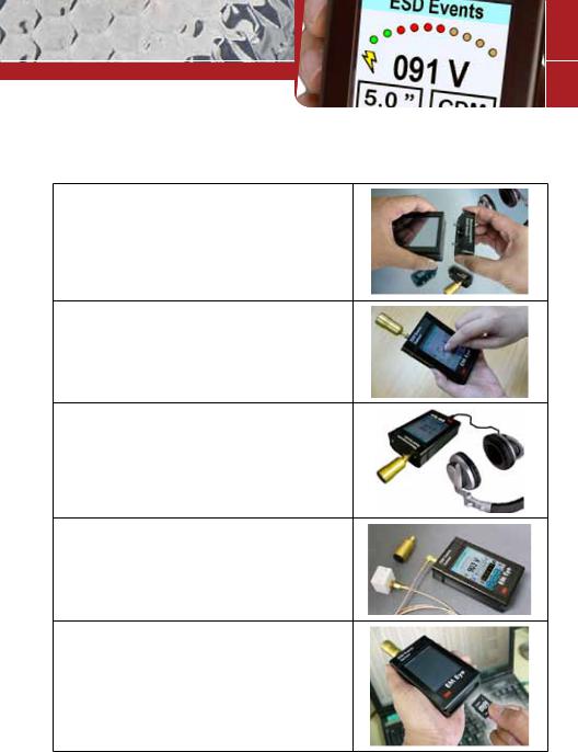
Attaching the Sensor Heads
Please keep in mind the following when using the modular sensor heads.
BEFORE CONNECTING TO AN INPUT SOURCE, TOUCH THE OUTSIDE SURFACE OF THE 3M™ EM EYE METER INPUT CONNECTOR. THIS WILL HELP PREVENT ESD SHOCK TO THE METER.
1.The power must be turned off when changing the sensor heads.
2.Make sure to gently plug or unplug the sensor heads.
3.Plug or unplug the sensor heads by gripping them firmly balanced on each side. Do not use the antenna for plugging and unplugging the sensor heads.
4.If the antenna is separated from the sensor head, reattach it when the sensor head is securely in place.
Attaching the Antenna
In order to avoid damaging the EM Eye Meter, installation and replacement of the antenna must be done with great care. An excessive amount of force or improper installation may permanently damage the meter.
Attach the antenna to the input connector by simply screwing it in by hand.
DO NOT OVERTIGHTEN THE CONNECTION. Screw in the antenna firmly but gently. Do not use any tools other than your hand to attach and detach the antenna.
9

Power Supply and Charger
Use only the power supply that comes with the 3M™ EM Eye Meter. Do not use any other power supply as it may damage the meter.
Battery Care
Charging for the first time
To improve the battery life we recommend that you make three fully charge-discharge cycles. For example: fully charge the meter for two hours or overnight, then use the meter until it is fully discharged (do not recharge it at half-charge-life). Repeat this step two times. It would normally take two hours to fully charge the battery, but since the meter power is on while charging; it would extend the charge time to four hours.
Succeeding charging would be at any duration. Use only the supplied charger.
Power On
Using your finger, press and hold any spot on the screen for approximately three seconds – do not use any tools to perform this action. If a new sensor was installed, a sequence of initialization will take place for the first time for approximately ten seconds. After that, the switch-on action will take approximately three seconds. The main display screen appears after the initialization and a beep will sound. The EM Eye Meter will then perform a battery check. If the battery is too low to provide reliable operation, it will not turn on. The screen will go white momentarily and then the meter will power up. After the initial power up, the meter will go directly to the main screen.
10

Connecting Up
ESD Events Meter |
EM Field Meter |
RF Meter |
Antenna CTS001 |
Antenna CTS001 |
(External cable sources) |
|
|
|
|
|
ESD Event Module |
Electromagnetic Field |
RF Signal Module |
|
Module |
|||
|
|
||
|
|
|
|
Base EM Eye |
Base EM Eye Meter Module |
Base EM Eye Meter Module |
|
Meter Module |
|||
|
|
||
|
|
|
|
Memory Card |
Memory Card |
Memory Card |
|
(miniSD™ card) |
(miniSD™ card) |
(miniSD™ card) |
|
Format: FAT32 |
Format: FAT32 |
Format: FAT32 |
|
512 Mb, 1 Gb, 2 GB |
512 Mb, 1 Gb, 2 GB |
512 Mb, 1 Gb, 2 GB |
|
*Supplied with miniSD |
*Supplied with miniSD |
*Supplied with miniSD |
|
and regular SD card adapter |
and regular SD card adapter |
and regular SD card adapter |
|
|
|
|
|
Power Supply/Charger |
Power Supply/Charger |
Power Supply/Charger |
|
*Not included: Australian power plug |
*Not included: Australian power plug |
*Not included: Australian power plug |
|
|
|
|
|
3M™ Remote Antenna |
3M™ Remote Antenna |
RF Cable BNC connector |
|
CTC113 |
CTC113 |
20db Attenuator |
|
CTC115 (high temperature) |
CTC115 (high temperature) |
|
|
|
|
* Included with the purchase of the |
|
*Not included: order separately |
*Not included: order separately |
CTC029 model. Otherwise needs to |
|
be ordered separately. |
|||
|
|
11
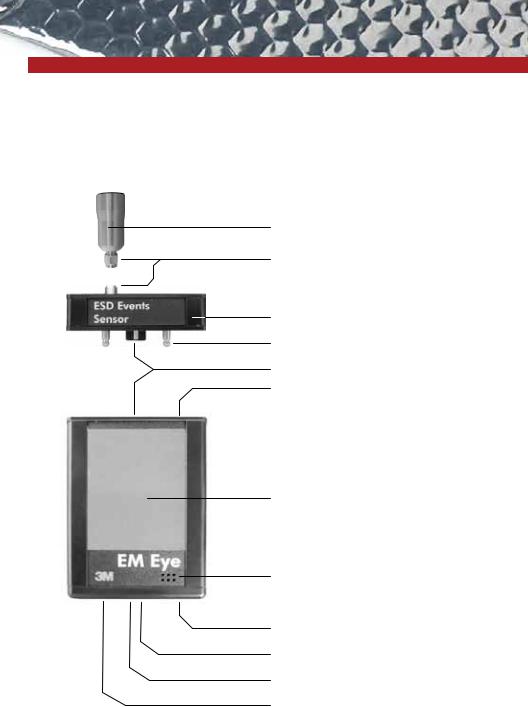
Parts Description
Local directional antenna
SMA connector (M/F)
Sensor module
Alignment pin
Connector (M/F)
Alignment hole
Main body
Touch screen and display
Speaker
Storage miniSD™ card
Headphone jack
Reset pinhole
Power adapter jack
12
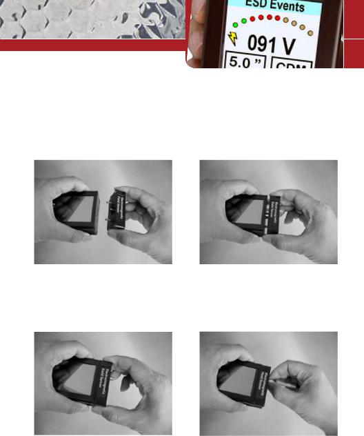
Modular Assembly and Disassembly
Carefully insert the sensor head and antenna to avoid damaging the 3M™ EM Eye Meter.
1. Position the sensor head so that the dowel pins align with the holes.
3. Press the sensor head firmly against the body until both surfaces are flat with each other.
2. With the initial head midway through, reposition it so that it is parallel to the body.
4. Insert and screw in the antenna making sure that it’s not too tight or too loose. Do not use any tools other than your hand.
(*Note: Antenna is not applicable for the RF Signal Sensor.)
13
If the assembly isn’t done correctly, you may receive one of the following error and warning messages. To correct, follow the instructions as indicated within the message.
ERROR: Sensor is |
|
ERROR: Card was |
|
ERROR: Card was |
disconnected. Click here |
|
removed. Data may be |
|
removed. Data may be |
to turn device off. |
|
lost and card could be |
|
lost and card could be |
|
|
damaged. Click here to |
|
damaged. Click here to |
|
|
close the window. |
|
close the window. |
|
|
|
|
|
|
The meter is turned on |
|
The storage card (miniSD™) |
|
The meter is turned on with |
|
|
without the sensor module. |
|
is removed while the meter |
|
no storage card in place. |
|
|
|
|
is powered on. |
|
|
|
|
|
|
|
|
|
|
|
|
|
|
|
|
|
|
ERROR: Card was |
|
ERROR: Card was |
|
ERROR: Invalid memory |
|
|
removed. Data may be |
|
removed. Data may be |
|
|
|
|
|
|
card. Format or replace it. |
|
||
|
lost and card could be |
|
lost and card could be |
|
|
|
|
|
|
Click here to close the |
|
||
|
damaged. Click here to |
|
damaged. Click here to |
|
|
|
|
|
|
window. |
|
||
|
close the window. |
|
close the window. |
|
|
|
|
|
|
|
|
||
|
|
|
|
|
|
|
|
A new card is inserted or |
|
Inserting a card that has |
|
The card is not formatted to |
|
|
when a card is empty. |
|
contents other than the |
|
FAT32. Formatting is done |
|
|
|
|
3M™ EM Eye Meter files. |
|
using the PC. |
|
ERROR!!!
STACK OVERFLOWED
Click here to turn device off.
This is a fatal error. If it appears even after resetting, please contact 3M.
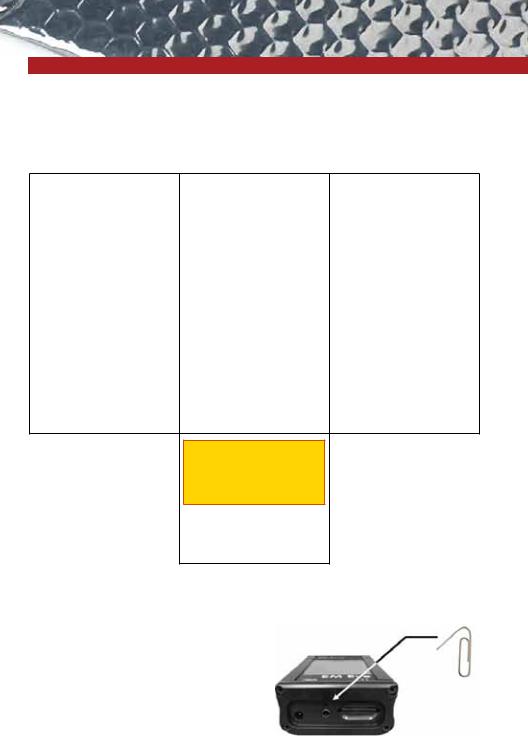
Reset Button
If the EM Eye Meter locks up or the display freezes, press the reset button to restart the meter.
The reset button is in a small hole found near the power supply jack. Use an unbent paper clip to push the button inside the small hole.
14
 Loading...