

Page 1
100BASE-FX F
R
Module Description This module contains one (1) Fast Ethernet 100BASE-FX port that uses an
M
ODULE
For the LANplex 2500
FDDI (SC) connector, providing a 100Mbps Fast Ethernet connection over
fiber. This module is fully compliant with all IEEE 802.3u specifications.
For a description of how to configure this module into your network, refer
to the LANplex documentation set.
The 100BASE-FX Fast Ethernet module requires revision 7.0 or later of
LANplex system software and revision 3.02 or later of system diagnostics. A
system software revision supporting this module is available from the 3Com
BBS, the Internet FTP site (3Com.ftp.com), or 3ComForum on CompuServe.
CAUTION: You must install revision 7.0 or later of LANplex system software
before you insert the 100BASE-FX module. Inserting the module when the
correct software is not running causes continuous system resets.
I
NSTALLATION
AST
E
THERNET
G
UIDE
100BASE FX
Board
Error
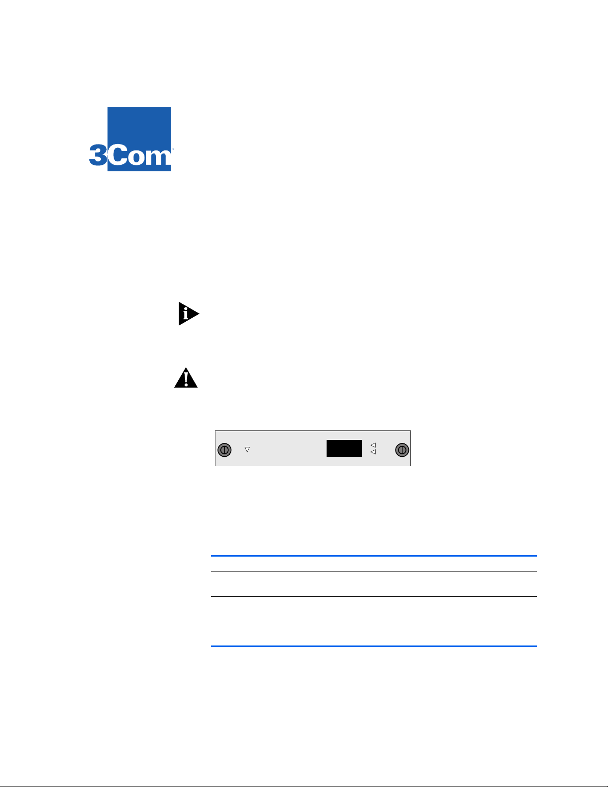
Status LEDs The option module contains one Board Error LED, one port status Active
LED, and one port status Error LED. Depending on the condition, the port
status LED is either
a description of the status LEDs.
.
LEDs Name Color Description
Module
Status
Port
Status
Board Error Yellow Indicates that either an error has occurred or the
Active Green Indicates that the associated port is active
Error Yellow Indicates that an error condition has occurred with
Active (green) or Error (yellow). See the table below for
Port Status
Active
Error
option module has failed a diagnostic procedure
the associated port or that the port was disabled
from the Administration Console
Page 2
1
2
Safety Information Electrostatic discharge (ESD) can damage components on the module. ESD
occurs when the module is improperly handled and can cause complete or
intermittent failures. To prevent ESD-related damage:
Always wear the ESD wrist strap provided with the LANplex system,
■
ensuring that it makes good skin contact
Keep the module in its antistatic shielded bag until you are ready to install it
■
■
Do not touch the components, pins, leads, or solder connections
Always handle the module by its edges
■
Prior to Installation Before you install your new module, follow the pre-installation instructions
below:
Read if initial
installation
Installing the
Module
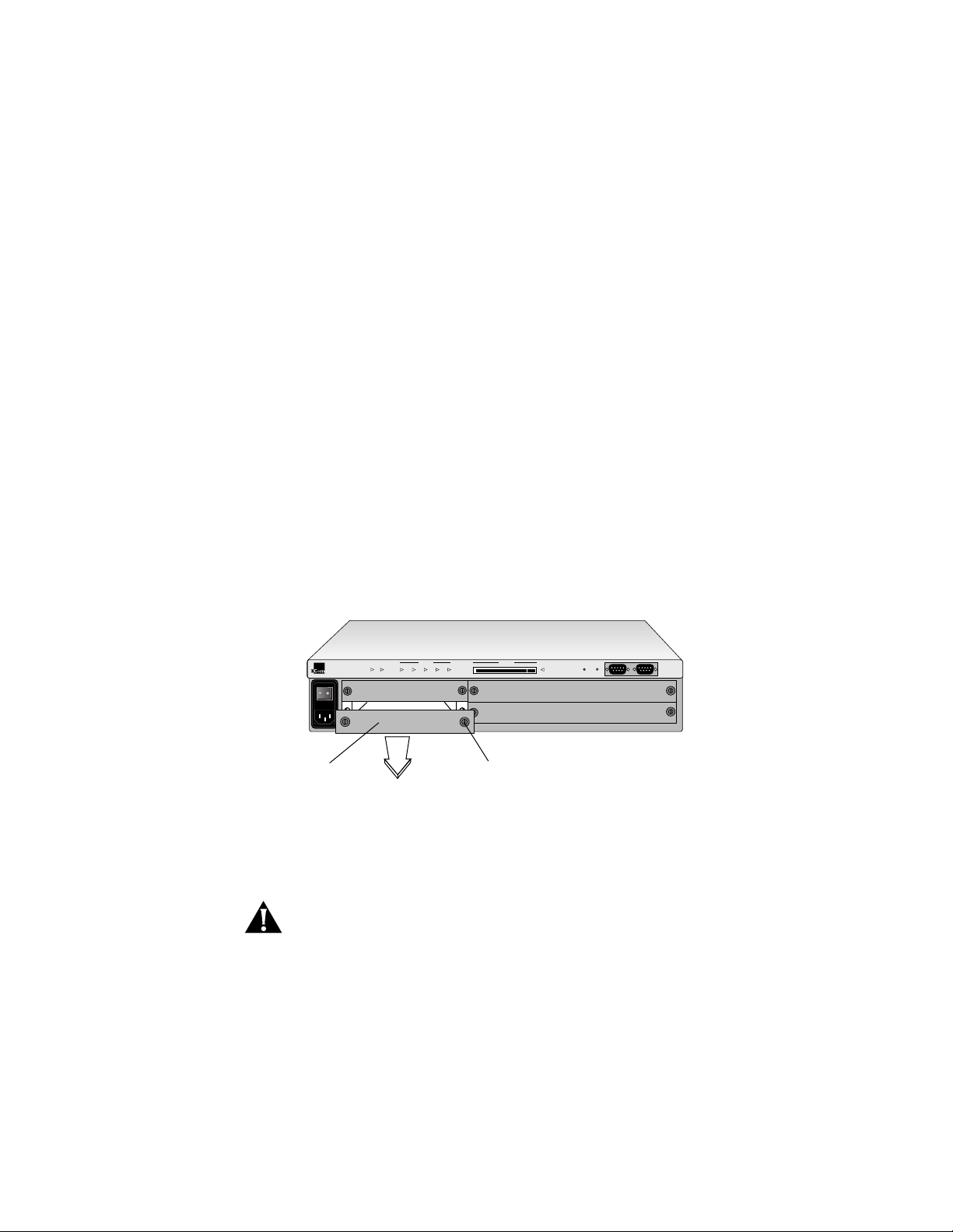
Your LANplex system is shipped without modules installed and with
protective faceplates covering the installation slots. Initial installation
requires that you remove the protective faceplate covering the selected
installation slot prior to installing the option module.
To remove the faceplate: 1) loosen the two captive screws securing the
faceplate to the chassis and 2) pull the faceplate away from the system.
R
LANplex 2500
Faceplate
Power Run
ERROR PCMCIA
Processor Power
Config Inserted
Fan Temp
Captive screw
To install the new module into the LANplex system, follow these steps:
CAUTION: When handling modules, 3Com recommends that you always use
a wrist strap connected to a proper ground. This helps prevent the module
from being damaged by electrostatic discharge. Additionally, when not in
use, the module should be stored in an antistatic bag.
Ensure that you are properly grounded.
Remove the module from its antistatic bag.
Page 3
3
4
5
WARNING:
If the system is powered on when you are installing the module,
do not insert any metal objects into the open slot (for example, a screwdriver
or a finger with jewelry). This could cause burns or other bodily harm.
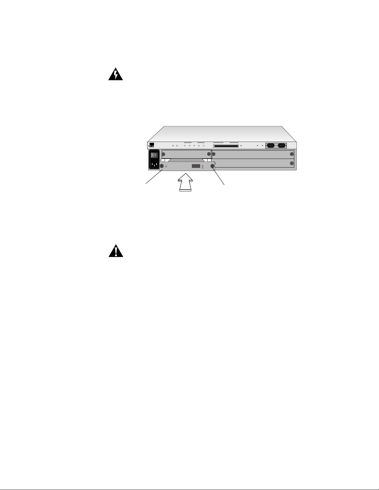
Place the module between the guides of the selected slot and slide the
module into the chassis. See the figure below.
R
LANplex 2500
100BASE-FX
option module
Power Run
Board
Error
ERROR PCMCIA
Processor Power
Config Inserted
Fan Temp
100 Base FX
Port Status
Active
Error
Captive screw
To seat the module, firmly push the module forward to engage the module
and backplane connectors. You will feel a slight resistance as the connectors
engage.
CAUTION: If the resistance is too great, the module and backplane
connectors may not be aligned. Forcing the module forward could damage
the board or backplane connectors. If necessary, remove and reinsert the
module, ensuring that the connectors are properly aligned. You should not
have to seat the module by tightening the captive screws.
Read if adding or
replacing a module
Tighten the captive screws to secure the module in the chassis.
Once the module is installed, see Chapter 4:
Cabling the System in your
Getting Started guide for information on cabling your module to the
network.
You can add or replace a module while the system is powered on.
To replace a module: 1) disconnect the cable from the module’s port(s) 2)
loosen the two captive screws securing the module to the chassis and 3)
pull the module out of the chassis.
Page 4
Option Module
Diagnostics
R
LANplex 2500
Green = Active
Yellow = Error
Board Error
Inserted
Board
Error
Power Run
ERROR PCMCIA
Processor Power
1
Config Inserted
Fan Temp
Port Status
Active
Error
2
100 Base FX
Port Status
Active
Error
Green = Active
Yellow = Error
Green = Active
Yellow = Error
Port Status
Board
Error
Board
Error
Active
Error
12345678
Port Status
Active
Error
100BASE-FX
option module
Captive screw
Male SC
connector
The LANplex system will automatically reset when a module has been
installed with the power on.
If you physically change the configuration of the system after defining an IP
interface, the port designated for that interface may no longer be valid. You
may have to redefine the interface. For information on defining an IP
interface, see the Administration Console User Guide for your LANplex
system.
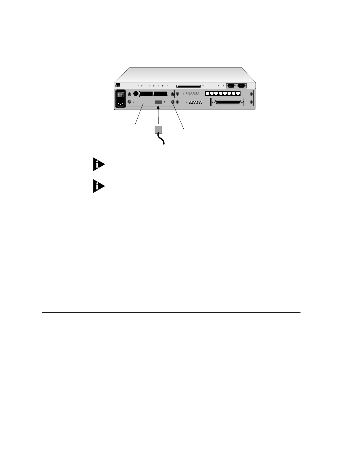
Module diagnostics run at power up or when replacing a module with the
power on. During diagnostics, the module’s port status
yellow. When diagnostics are successfully completed, the port status
LED turns green. If the port status
operational. If the module’s
Error LED remains yellow, the port is not
Board Error LED is lit yellow, the module has
Error LED is lit
Active
failed a diagnostic test. To troubleshoot module failures, see Chapter 7:
Troubleshooting the System in your Getting Started guide .
3Com Corporation
5400 Bayfront Plaza
Santa Clara, California
95052-8154
© 3Com Corporation, 1996. All rights reserved. No part of this documentation may be reproduced in any form
or by any means or used to make any derivative work (such as translation, transformation, or adaptation)
without permission from 3Com Corporation.
3Com Corporation reserves the right to revise this documentation and to make changes in content from time
to time without obligation on the part of 3Com Corporation to provide notification of such revision or change.
3Com Corporation provides this documentation without warranty of any kind, either implied or expressed,
including, but not limited to, the implied warranties of merchantability and fitness for a particular purpose.
3Com may make improvements or changes in the product(s) and/or the program(s) described in this
documentation at any time.
3Com and LANplex are registered trademarks of 3Com Corporation. 3Com registered trademarks are registered
in the United States, and may or may not be registered in other countries. Other brand and product names
may be registered trademarks or trademarks of their respective holders.
Part No. 801-00304-000
Published March1996
Revision 01
 Loading...