

Page 1

Part No. 206380-A
September 1999
4401 Great America Parkway
Santa Clara, CA 95054
Installation and Reference for the BayStack 22 PC Card Adapter
Page 2

Copyright © 1999 Nortel Networks
All rights reserved. September 1999.
The information in this document is subject to change without notice. The statements, configurations, technical data,
and recommendations in this document are believed to be accurate and reliable, but are presented without express or
implied warranty. Users must take full responsibility for their applications of any products specified in this document.
The information in this document is proprietary to Nortel Networks NA Inc.
Trademarks
NORTEL NETWORKS is a trademark of Nortel Networks.
Bay Networks is a registered trademark and BayStack and the Nortel Networks logo are trademarks of Nortel
Networks.
Microsoft, Windows, and Windows NT are registered trademarks of Microsoft Corporation.
All other trademarks and registered trademarks are the property of their respective owners.
Notice
Note: This equipment has been tested and found to comply with the limits for a Class A digital device, pursuant to
Part15 of the FCC rules. These limits are designed to provide reasonable protection against harmful interference
when the equipment is operated in a commercial environment. This equipment generates, uses, and can radiate radio
frequency energy. If it is not installed and used in accordance with the instruction manual, it may cause harmful
interference to radio communications. Operation of this equipment in a residential area is likely to cause harmful
interference, in which case users will be required to take whatever measures may be necessary to correct the
interference at their own expense.
EN 55 022 Statement
This is to certify that the Nortel Networks BayStack 22 PC Card Adapter is shielded against the generation of radio
interference in accordance with the application of Council Directive 89/336/EEC, Article 4a. Conformity is declared
by the application of EN 55 022 Class A (CISPR 22).
Warning: This is a Class A product. In a domestic environment, this product may cause radio interference, in which
case, the user may be required to take appropriate measures.
EC Declaration of Conformity
This product conforms to the provisions of Council Directive 89/336/EEC and 73/23/EEC. The Declaration of
Conformity is available on the Nortel Networks World Wide Web site at http://libra2.corpwest.baynetworks.com/
cgi-bin/ndCGI.exe/DocView/.
ii
206380-A
Page 3

Voluntary Control Council for Interference (VCCI) Statement
Voluntary Control Council for Interference (VCCI) Statement
This is a Class A product based on the standard of the Voluntary Control Council for Interference by Information
Technology Equipment (VCCI). If this equipment is used in a dom estic env ironment, radio disturbance may ari se.
When such trouble occurs, the user may be required to take corrective actions.
Canadian Department of Communications Radio Interference
Regulations
This digital apparatus (BayStack 22 PC Card Adapter) does not exceed the Class A limits for radio-noise emissions
from digit al apparatus as s et out in the Radio Interference Regulations of the Canadian Department of
Communications.
Règlement sur le brouillage radioélectrique du ministère des
Communications
Cet appare il numérique (BayStack 22 PC Card Adapter) respecte le s limites de bruit s radioélectr iques visant le s
appareils numériques de cla sse A prescrites dans le Règlement sur le brouillage radioélectrique du ministère des
Communications du Canada.
Electromagnetic Interference (EMI) Statement
206380-A
iii
Page 4

Wichtige Sicherheitshinweise
1. Bitte lesen Sie diese Hinweis e sorgfaltig durch.
2. Heben Sie diese Anleitung fur den spateren Gebrauch auf.
3. Vor jedem R einigen ist das Gerat vom Stromnetz zu trennen. Verwenden Sie keine Flussigoder Aerosolreiniger.
Am besten eignet sich ein angefeuchtetes Tuch zur Reinigung.
4. Um eine Beschadigung des Gerate s zu vermeiden sollten Sie nur Zubehorteile verwenden, die vom Hers teller
zugelassen sind.
5. Da s G e rat ist vor Feu ch tigkeit zu schutze n.
6. Bei der Aufstellung des Gerat es ist auf sicheren Stand zu achten. Ein Kippen oder Fallen konnte Verletzungen
hervor rufen. Verwenden Sie nur sichere Standorte und beachten Sie die Aufstellhinweise des Herstellers.
7. Die Beluftungsoffnungen dienen der Luftzirkulation die das Gerat vor Uberhitzung schutzt. Sorgen Sie dafur,
daB diese Of fnungen nicht ab gedeckt werden.
8. Beachten Sie beim AnschluB an das Str om netz die AnschluBwerte.
9. Die Netzanschlusteckdose muB aus Grunden der elektrischen Sicherheit einen Schutzleiterkontakt haben.
10. Verlegen Sie die N etzanschluBle itung so, da B niemand daruber fallen kann. Es sollte auch nic hts auf der Leitung
abgestellt werden.
11. Alle Hinweise und Warnungen, die sic h am Geraten befinden sind zu beachten.
12. Wird das Gerat uber einen langeren Zeitraum nicht benutzt, sollten Sie es vom Stromnetztrennen. Somit wird im
Falle einer Uberspannung eine Beschadigung vermieden.
13. Durch die Luf tungsoffnungen durfen niemals Ge genstande oder Flussigkeiten in das Gerat gelange n. Dies
konnte einen Brand bzw. elektrischen Schlag auslosen.
14. Offnen sie niemals das Gerat. Das Gerat darf aus Grunden der elektrischen Sicherheit nur von authorisiertem
Servicep ersonal geoffnet werden.
15. Wenn folgende Situationen auftreten ist das Gera t vom Stromnetz zu trennen und von einer qualifizierten
Servicestelle zu uberprufen:
a. Netzkabel oder Netzstecker sind beschadigt.
b. Flussigkeit ist in das Gerat eingedrungen.
c. Das Gerat war Feuchtigkeit ausgesetzt.
d. Wenn das Gerat nicht der Bedienungsanleitung entsprechend funktioniert oder Sie mit Hilfedieser Anle itung
keine Verbesserung erzielen.
e. Das Gerat ist gefallen und/oder das Gehause ist beschadigt.
f. Wenn das Gerat deutliche Anzeichen eines Defektes aufweist.
16. Bei Reparaturen durfen nur Or ginalersatzteile bzw. den Orginalteilen entsprechende Te ile verwendet werden.
Der Einsatz von ungeeigneten Ersatzteilen kan n eine weitere Beschadigung hervorrufen.
17. Wenden Sie sich mit allen Fragen die Service und Repartur betreffen an Ihren Servicepartner. Somit stellen Sie
die Betriebssicherheit des Gerates sicher.
18. Zum NetzanschluB dieses Gera tes ist eine geprufte Leitung zu verw enden. Fur einen Nen nstrom bis 6A und
einem Gerategewicht groBer 3kg ist eine Leitung nicht leichter als H05VV-F, 3G, 0.75mm 2 einzusetzen.
Der arbeitsplatzbezogene Schalldruckpegel nach DIN 45 635 Teil 1000 betragt 70dB(A) oder weniger.
iv
206380-A
Page 5

Restricted Rights Legend
Use, duplication, or disclosure by the United States Government is subject to restrictions as set forth in subparag raph
(c)(1)(ii) of the Rights in Techni cal Data and Computer Software clause at DFARS 252.227-7013.
Notwithstanding any other license agreement that may pertain to, or accompany the delivery of, this computer
software, the rights of the United States Governm ent regardi ng its use, reproduction, and di sclosure are as set forth in
the Commercial Computer Softw are-Restric ted Rights clause at FAR 52.227-19.
Statement of Conditions
In the interest of im proving internal desig n , operational function, and /or reliabil ity, Nortel Networks NA Inc. reserves
the right to m ake changes to the products described in this document without notice.
Nortel Net w orks NA Inc. does not assume any liability that may occur due to the use or application of the product(s)
or circuit layout(s) described herein.
Portions of the code in this software product are Copyright © 1988, Regents of the Uni versity of California. All rights
reserv ed. Redistribution and use in source and binary forms of such portions are permitted, provided that the above
copyrig ht not ic e an d th is par agr ap h ar e dupli ca te d in all su ch f or ms and th at a ny doc um enta ti on, adve rt is in g mat eria ls ,
and other materials related to such distribution and use acknowledge that such portions of the software were
developed by the University of California, Berkeley. The name of the University may not be used to endorse or
promote products derived from such portions of the softw are without specific prior written permi ssion.
SUCH PORTIONS OF THE SOFTWARE ARE PROVIDED “AS IS” AND WITHOUT ANY EXPRESS OR
IMPLIED WARRANTIES, INCLUDING, WITHOUT LIMITATION, THE IMPLIED WARRANTIES OF
MERCHANTABILITY AND FITNESS FOR A PA RTICULAR PURPOSE.
Nortel Networks NA Inc. Software License Agreement
NOTICE: Please carefully read this license agreement before copying or using the accompanying software or
instal ling the hardware unit with pre-enabled software (each of which is r eferred to as “Software” in t h is Agreement).
BY COPYING OR USING THE SOFTWARE, YOU ACCEPT ALL OF THE TERMS AND CONDITIONS OF
THIS LICENSE AGREEMENT. THE TERMS EXPRESSED IN THIS AGREEMENT ARE THE ONLY TERMS
UNDER WHICH NORTEL NETWORKS WILL PERM IT YOU TO USE THE SOFTWARE. If you do not accept
these ter ms and conditions, return the product, unused and in the original shipping container, within 30 days of
purchase to obtain a credit for the full purchase price.
1. License Grant. Nortel N e tworks NA Inc. (“Nortel Networks”) grants the end user of the Sof tware (“Licensee”) a
personal, no ne xcl usi v e , nontr ans fe rabl e li cense: a) t o use th e Softw are eit her on a si ngl e compu ter or, if applica bl e, on
a single authorized device identified by host ID, for which it was originally acquired; b) to copy the Software solely
for backup purposes in suppo rt of authorize d use of the Software; and c) to use and copy the associated user manual
solely in support o f authorized use of the Software b y Licensee. T his license applies to the Software only and does not
extend to Nortel Networks Agent software or other Nortel Networks software products. Nortel Networks Agent
software or other Nortel Ne tworks software products are licensed for use under the terms of the applicable No rtel
Networks NA Inc. Software Lic ense Agreement that accompa nies such software and upon payment by the end user of
the applicable license fees for such software.
2. Restrictions on use; reservation of right s. The Software and user manuals are protected under copyright laws.
Nortel Net w orks and/or its licensors retain all title and o w nership in both the Software and user manuals, including
any re visions made by Nortel Networks or its licensors. The copyright notice must be reproduced and included with
any copy of any p orti on of the Soft war e or user manual s. Lic ensee m ay not m odify, trans la te , decom pile , disa ss embl e,
use for any competitive analysis, reverse engineer, distribute, or create derivative works from the Software or user
manuals or any copy, in whole or in p art. Except as e xpressly provi ded in this Agreem ent, Licensee may not copy or
transfe r the Software or user manuals, in whole or in part. The Software and user manuals embody Nortel Networks’
206380-A
v
Page 6

and its licensors’ c onfidentia l and proprietary intellectual propert y. Lic ensee shall not sublicense, assign, or otherwise
disclose to any third party the Software, or any informati on about the operation, design, performance, or
implementation of the Software and user manuals that is confidential to Nortel Networks and its licensors; however,
Licensee m ay grant permission to it s consultants, subcontrac tors, and agents to use the Software a t Licensee’s facility,
provided they have agreed to use the Software only in accordance with the terms of this l icense.
3. Limited warranty. Nortel Net w orks warrants each i tem of Software, as de livered by Nortel Networks and properly
instal led and operated on Nortel Networks h ardware or other equipment it is originally licensed for, to function
substantially as described in its accompan ying user manual dur ing its warranty period, which be gins on the date
Softwar e is f ir st shi ppe d to Licen see . I f any it em of Soft wa re fai l s to so func ti on during i ts warr anty pe ri od, as the so le
remedy Norte l Net wor ks will at it s discr et ion pro vi de a suita bl e fix , pat ch , or worka ro und fo r the p roble m that may be
included in a future Software release. No rtel Networks further warra n ts to Licensee tha t the media on which the
Softwar e is provided will be free from defects in materials and workmanship under normal use for a period of 90 days
from the date Software is first shipped to Licensee. Nort el N etworks will replace defective media at no ch arge if it is
returned to Nortel Networks during the w arranty period along with proof of the date of shipment . This warranty does
not apply if the media has been damaged as a result of accident, misuse, or abuse. The Licensee assumes all
resp on s ib ility for selectio n of the Sof tw ar e to achieve Li ce n se e’s intended res ul ts and for th e in stallation, use , an d
results obtained from the Software. Nortel Ne tworks does not war rant a) that the functions contained in the software
will meet the Licensee’s requirements, b) that the Software will operate in the hardware or software combinations that
the Licensee may select, c) that the operat ion of the Software will be uninterrupted or error free, or d) that all defects
in the oper ation of the Software will be corrected. Nortel Networks is not obl igated to remedy any Software defect
that canno t be repr od uce d with the lat es t Soft war e re lease . Th ese war ranti es do not appl y to the So ftw are i f it has been
(i) altered, except by Nortel Networks or in accordance with its inst ructions; (ii) used in conjunction with another
vendor’s product, resulting in the defect; or (iii ) dam aged by improper environme nt, abuse, misuse, accident, or
negligence. THE FOREGOING WARRANTIES AND LIMITATIONS ARE EXCLUSIVE REMEDIES AND ARE
IN LIEU OF ALL OTHER WARRANTIES EXPRESS OR IMPLIED, INCLUDING WITHOUT LIMITATION
ANY WARRANTY OF MERCHANTABILITY OR FITNESS FOR A PARTICULAR PURPOSE. Licensee is
responsible for the security of its own data and information and for maintaining adequate procedures apar t from the
Softwar e to reconstruct lost or altered files, data, or programs.
4. Limitation of liability. IN NO EVENT WILL NORTEL NETWORKS OR ITS LICENSORS BE LIABLE FOR
ANY COST OF SUBSTITUTE PROCUREMENT; SPECIAL, INDIRECT, INCIDENTAL, OR CONSEQUENTIAL
DAMAGES; OR ANY DAMAGES RESULTING FROM INACCURATE OR LOST DATA OR LOSS OF USE OR
PROFITS ARISI NG OUT OF OR IN CONNECTION WITH THE PERFORMANCE OF THE SOFTWARE, EVEN
IF NORTEL NETW ORKS HAS BEEN ADVISED OF THE POSSIBILITY OF SUCH DAMAGES. IN NO EVENT
SHALL THE LIABILITY OF NORTEL NETWORKS RELATING TO THE SOFTWARE OR THIS AGREEMENT
EXCEED THE PRICE PAID TO NORTEL NETWORKS FOR THE SOFTWARE LICENSE.
5. Gove rn m e nt Licensees. This provision ap plies to all Software and documentat ion acquired directly or indirectly
by or on behalf of the United States Government. The Software and documentation are commercial products, licensed
on the open market at market prices, and were developed enti rely at private expense and w ithout the use of any U.S.
Government funds. The license to the U.S. Government is granted only wi th restricte d rights, and use, duplication, or
disclos ure by the U.S. Government is subject to the restrictions set forth in subpara graph (c)(1) of th e Com mercial
Computer Sof tware––Restr icted Rights clause of FAR 52.227-19 a nd the limitations set out in this license for civilian
agencies , and subparagrap h (c)(1)(ii) of the R ights in T echnical Data and Co mp uter Software cl ause of DFARS
252.227- 7013, for agencies of the Department of Defense or their successors, whichever is applicable.
6. Use of Software in the European Community. T hi s pr ovision ap p lies to all So ftware ac q uired for use within th e
European Community. If Licensee uses the Software withi n a country in the Euro pean Community, the Software
Directive enacted b y the Council of Europ ean Communities Directive da ted 14 May, 1991, will apply to the
examination of the Software to facilit ate interoperability. Licensee agre es to notify Nortel Networks of any su ch
intended examination of the Software and ma y p rocure support and assistance from Nor tel Networks.
vi
206380-A
Page 7

7. Term and termination. This license is effective unt il terminated; however, all of the restrictions w ith respect to
Nortel N etworks’ copyright in the Software and user man uals will cease being effectiv e at the d ate of expiration of the
Nortel Networks copyright; those restrictions relating to use and disclosure of Nortel Networks’ confidential
information shall continue in effect. Licensee may terminate this license at any time. The license will automatically
terminate if Licensee fails to comply with any of the terms and conditions of the license. Upon termination for any
reason, Licensee will immediately destroy or return to Nortel Networks t h e Software, user ma nuals, and all copies.
Nortel Networks is not liable to Licensee fo r damages in any form solely by reason of the termin ation of this lic ense.
8. Export and Re-export. Licensee agrees not to export, directly or indirectly, the Software or related technical data
or information without first obtaining any required export licenses or other governmental approvals. Without limiting
the foregoing, Licen see, on behalf of itself and its subsidiaries a nd affiliates, agrees that it will not, w ithout fir s t
obtaining all export licenses and appro vals required by the U.S. Gove rnment: (i) export, re-expo rt, transfer, or diver t
any such Sof tware or technical data, or any direct product thereof, to any country to which such exports or re-exports
are rest ricted or embar goed under United States export control laws and regulations, or to any natio nal or resident of
such rest ricted or embargoed countries; or (ii) provide the Software or related tec hnical data or in formation to any
military end user or for any mi litary end use, including the design, developm ent, or production of any chemical,
nuclear, or biological weapons.
9. General. If any provision of this Agreement is held to be invalid or unenforceable by a court of competent
jurisdiction, the remainder of the provisions of this Agreement shall remain in full force and effect. This Agreement
will be go verned by the la w s of the state of California.
Should you have any questions concerning this Agreement, co ntact Nortel Networks, 4401 Great A m erica Parkway,
P.O. Box 58185, Santa Clara, Cal ifornia 95054-8185.
LICENSEE ACKNOWLEDGES THAT LICENSEE HAS READ THIS AGREEMENT, UNDERSTANDS IT, AND
AGREES TO BE BOUND BY ITS TERMS AND CONDITIONS. LICENSEE FUR THER AGREES THAT THIS
AGREEMENT IS THE ENTIRE AND EXCLUSIVE AGREEMENT BETWEEN NORTEL NETWORKS AND
LICENSEE, WHICH SUPERSEDES ALL PRIOR ORAL AND WRITTEN AGREEMENTS AND
COMMUNICATIONS BETWEEN THE PARTIES PERTAINING TO THE SUBJECT MATTER OF THIS
AGREEMENT. NO DIFFERENT OR ADDITIONAL TERMS WILL BE ENFORCEABLE AGAINST NORTEL
NETWORKS UNLESS NORTEL NETWORKS GIVES ITS EXPRESS WRITTEN CONSENT, INCLUDING AN
EXPRESS WAIVER OF THE TERMS OF THIS AGREEMENT.
206380-A
vii
Page 8

viii
206380-A
Page 9

Contents
Preface
Before You Begin .............................................................................................................xv
Text Conventions ................... ............ ............ ............ ............ ............ ........... ............ ....... xv
Technical Publications .....................................................................................................xvi
How to Get Help ..............................................................................................................xvi
Chapter 1
Introduction
BayStack 22 PC Card Adapter Overview .......................................................................1-1
Product Features ............................................................................................................1-1
Product Description ........................................................................................................1-2
BayStack 22 Network Card ......................................................................................1-2
68-Pin Connector ............................................................................................... 1-2
15-Pin Connector ............................................................................................... 1-3
Media Coupler ...................................................................................................1-3
System Require men ts ............................... ............ ................................. ............ ......1-5
Operating Environments ..........................................................................................1-6
Cable Requi re me n ts .......... ............ ................................. ................................. ........1-6
Fast Ethernet Cables (100 Mb/s) .......................................................................1-6
Ethernet Cables (10 Mb/s) ................................................................................. 1-6
Typical Applicati o n s .................... ............ ............ ............ ............ ........... ............ .............1-7
Chapter 2
Hardware Installati on
Package Contents ..........................................................................................................2-1
Installing the BayStack 22 PC Card Adapter ..................................................................2-2
Removing the BayStack 22 PC Card Adapter ................................................................2-3
206380-A
ix
Page 10

Chapter 3
Software Installation
Preinstallation ................................................................................................................. 3-2
Installing the Network Driver in a Windows 95 Environment ..........................................3-2
Configuring the Windows 95 Environment ........................................... .. .......... ....... .3-6
Installing the Network Driver in a Windows 98 Environment ........................................3-11
Configuring the Windows 98 Environment ........................................... .. .......... ......3-18
Configuring the Interrupt Request ..........................................................................3 -21
Installing the Network Driver in a Windows NT 4.0 Environment .................................3-23
Configuring the Windows NT Environment ............................................................3-27
Installing the Network Driver in a Novell NetWare 4.x Environment .............................3-32
Installing the Network Card in a Novell NetWare Server ........................................3 -32
Specifying Driver Parameters ..........................................................................3-35
Installing the Network Card in a Novell NetWare Client .........................................3-36
Chapter 4
Troubleshooting
Diagnostic LEDs .............................................................................................................4-1
Hardwar e Iss ues ......... ........... .................................. ........... .................................. ..........4-2
Software Issues ..............................................................................................................4-2
Appendix A
Technical Spec ifications
Product Specifications ...................................................................................................A-1
Software Drivers ............................................................................................................A-2
Appendix B
Novell NetWare Reference Information
Novell NetWare Server Files ..........................................................................................B-1
File Descriptions ...... ............ ............ ............ ............ ............ ........... ........................B-1
Sample AUTOEXEC.NCF Files ............................................................................... B-2
A UTO.EXEC.NCF File P a ra meters ..... ............ ............ ................................. ..... B-2
Novell NetWare Client Files ........................................................................................... B-4
Client Files .............................................................................................................. B-4
NET.CFG Files and Parameters .............................................................................. B-5
Sample NET.CFG File ......................................................................................B-5
NET.CFG File Parameters ................................................................................ B-5
Index
x
206380-A
Page 11

Figures
Figure 1-1. BayStack 22 Network Card Connectors .................................... ..... .... ..... .1-2
Figure 1-2. Media Coupler ..........................................................................................1-3
Figure 1-3. LEDs ........................................................................................................1-4
Figure 1-4. BayStack 22 Network Card Installation ....................................................1-7
Figure 1-5. Typical Application ...................................................................................1-8
Figure 2-1. BayStack 22 Network Card Installation ....................................................2-2
Figure 3 -1. New Hardware Found Window—Generic ................................................ 3-2
Figure 3 -2. New Hardware Found Window—BayStack 22 Networ k Card ..................3-3
Figure 3-3. Update Device Driver Wizard Dialog Box ................................................3-3
Figure 3-4. Copying Files Dialog Box .........................................................................3-4
Figure 3-5. Up date Device Dr iver Wizard Dialog B ox—BayStack 22 Network Card ..3-4
Figure 3 -6. S y stem Settings Change Dialog Box .......................................................3-5
Figure 3-7. Network Dialog Box—Configuration Tab ..................................................3-6
Figure 3 -8. P roperties Dialog Box ..............................................................................3-7
Figure 3-9. Resources Dialog Box .............................................................................3-8
Figure 3 -10. Select Network Component Type Dialog Box ..........................................3-9
Figure 3-11. Select Network Protocol Dialog Box ........................................................ 3-9
Figure 3 -12. TCP/IP Properties Dialog Box ...............................................................3-10
Figure 3 -13. New Hardware Found Window—Generic ..............................................3-11
Figure 3 -14. New Hardware Found Window—BayStack 22 Network Card . . .............. 3-12
Figure 3-15. Add New Hardware Wizard Dialog Box .................................................3-12
Figure 3-16. Add New Hardware Wizard—Driver Selection Dialog Box ....................3-13
Figure 3-17. Add New Hardware Wizard—Driver Location Dialog Box ......................3-14
Figure 3-18. Add New Hardware Wizard—Driver Search Dialog Box ........................3-15
Figure 3 -19. Insert Disk Message ..............................................................................3-15
Figure 3-20. Copying Files Dialog Box .......................................................................3 -16
Figure 3 -21. Add New Hardware Wizard—Installation Finished Dialog Box ..............3-17
206380-A
xi
Page 12

Figure 3 -22. System Settings Change Dialog Box . ....................................................3 -17
Figure 3-23. Network Dialog Box—Configuration Tab ................................................ 3 -18
Figure 3-24. BayStack 22 Network Driver Dialog Box—Advanced Tab ......................3-19
Figure 3-25. Access Control Tab ................................................................................ 3 -20
Figure 3-26. Resources Tab .......................................................................................3-21
Figure 3-27. Edit Interrupt Request Dialog Box ..........................................................3-22
Figure 3-28. Network Dialog Box—Adapters Tab .......................................................3-23
Figure 3 -29. Select Network Adapter Dialog Box . ......................................................3-24
Figure 3-30. Insert Disk Dialog Box ...........................................................................3-24
Figure 3-31. Select OEM Option Dialog Box ..............................................................3-25
Figure 3 -32. Windows NT Configuration Dialog Box ..................................................3 -26
Figure 3-33. Bindings Tab ..........................................................................................3-27
Figure 3 -34. Bindings Tab —All Adapters Selection ....................................................3-28
Figure 3-35. IP Address Tab .......................................................................................3-29
Figure 3-36. DNS Tab .................................................................................................3-30
Figure 3-37. WINS Address Tab .................................................................................3-31
xii
206380-A
Page 13

Tables
Table 1-1. LED Indications ........................................................................................1-5
Table 4-1. LED Indications ........................................................................................4-1
Table A-1. Technical Specific a ti o n s ...................... ............ ............ ........... ................. A-1
Table A-2. Available Software Drivers ......................................................................A-2
Table B-1. Server Files .............................................................................................B-1
Table B-2. Server Connection Type Parameters ...................................................... B -4
Table B-3. Client File s ....................... ............ ................................. ............ .............. B-4
Table B-4. Client Connection Type Parameters ........................................................B- 6
206380-A
xiii
Page 14

xiv
206380-A
Page 15

Congratulation s on your purchase of a BayStack™ 22 PC Card Adapter, which
supports 10 Mb/s and/or 100 Mb/s transmis sion spe eds. This network card is
intended for use in laptop comput ers. You can use a similar product, the
BayStack 21 PCI 10/100 Adapter w/WOL, in a desktop workstation or server.
Before You Begin
This guide provides information about using the features and capabilities of the
BayStack 22 PC Card Adapter.
Preface
This guide is intended for Ethernet local area network (LAN) administrators with
the follo wing background:
• Working knowledge of PC terminology and operation
• Working knowledge of 10BASE-T (Ethernet) and 100BASE-TX
(Fast Ethernet) operations
• Nortel Net works
Text Conventions
This guide uses the following text conventions:
bold text
separator ( > ) Shows menu paths.
206380-A
™
network experience
Indicates command names and options and text that
you need to enter.
Example: Enter
Example: From the Windows taskbar, choose Start >
Settings > Control Panel.
a:\
.
xv
Page 16

Installation and Reference for the BayStack 22 PC Card Adapter
Technical Publications
You can print selected technical manuals and release notes free, directly from the
Internet. Go to support.baynetw ork s.c om/library/tpubs/. Find the product for
which you need documentation. Then locate the specific category and model or
version for your hardw are or softwa re product. Using Adobe Acrobat Reader, you
can open the manuals and release notes, search for the sections you need, and prin t
them on most standard printers. You can download Acrobat Reader free from the
Adobe Systems Web site, www.adobe.com.
How to Get Help
If you purchase d a se rvi ce con t ract fo r your Nortel Networks product from a
distributor or authorized reseller, contact the technical support staff for that
distributor or reseller for assistance.
If you purc hased a Nortel Netw orks service program, contact one of the f ollowing
Nortel Networks T e chnical Solutions Centers:
T echnical Solutions Center Telephone Number
Billerica, MA 800-2LANWAN (800-252-6926)
Santa Clara, CA 800-2LANW AN (800-252-6926)
Valbonne, France 33-4-92-96-69-68
Sydney, Australia 61-2-9927-8800
Tokyo, Japan 81-3-5402-7041
#
206380-A
Page 17
Chapter 1
Introduction
This chapter provides an overview of the BayStack 22 PC Card Adapter,
including its hardware and software components. The BayStack 22 PC Card
Adopter complements the BayStack 70-Series 10/100 Ethernet Switches and
BayStack 60-Series 10/100 Ethernet Hubs.
The BayStack 22 PC Card Adapter, also known as the BayStack 22 PC
Note:
Card Adopter in this document, may also be referred to as a PCMCIA Ethernet
Adapter.
BayStack 22 PC Card Adapter Overview
The BayStack 22 PC Card Adapter provide s netw ork connectivity to laptop
computers. You install the network card into your comput er to access network
resources such as se rvers, printers, and th e Inte rnet or intranet. You can install the
BayStack 22 PC Card Adopter on many operating systems, such as Microsoft®
Windows® 95, Windows 98, and Windows NT® or Nove ll N e t Ware.
Product Features
The BayStack 22 PC Card Adopter provides the fol lowing features:
• Plug-and-play installation for Windows 95 and Windows 98
• 10/100 Mb/s autonegotiation with half- and full-duplex support
• 20/200 Mb/s full- duplex support
206380-A
1-1
Page 18
Installation and Reference for the BayStack 22 PC Card Adapter
Product Description
The BayStack 22 PC Card Adapter is a standard-size PCMCIA card. A media
coupler provides network access to your laptop computer.
BayStack 22 Network Card
The BayStack 22 PC Card Adapter includes the following components:
• 68-pin connector
• 15-pin connector
• Media couple r, including:
— 10 megabits per second (Mb/s) and 100 Mb/s Link LEDs
— Activity LED
— 15-slot connector
— RJ-45 port
68-Pin Connector
1-2
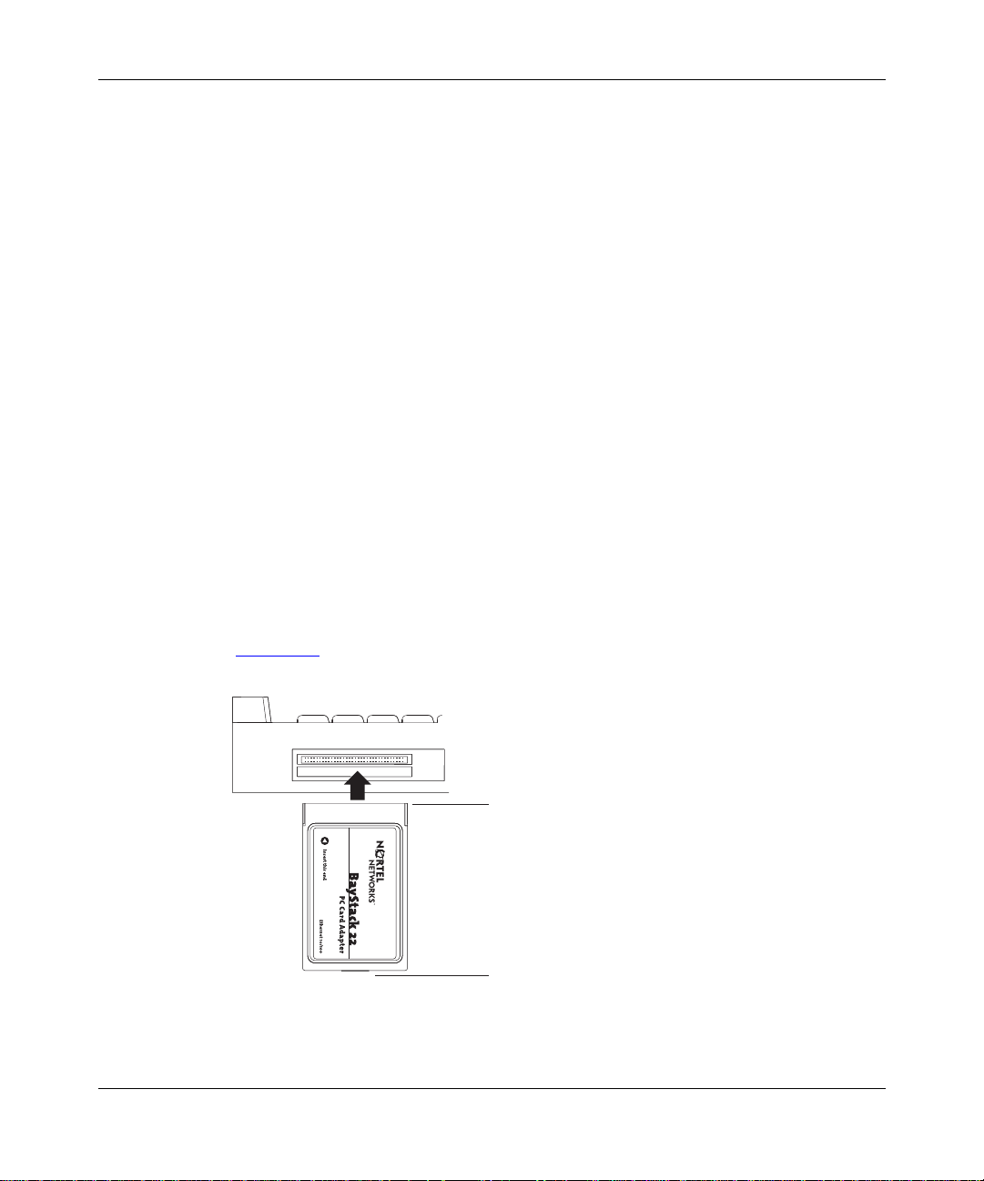
The standard 68-pin connect or on one end of the BayStack 22 PC Card Adopter
(Figure 1-1
Figure 1-1. BayStack 22 Network Card Connectors
) plugs into the Type II or Type III slot on your computer.
68-pin connector
15-pin connector
9493EA
206380-A
Page 19
Introduction
15-Pin Connector
The standard 15-pin connect or on the other end of the BaySt ack 22 PC Card
Adopter (Figure 1-1
) attaches to the 15-slot connector on the media coupler.
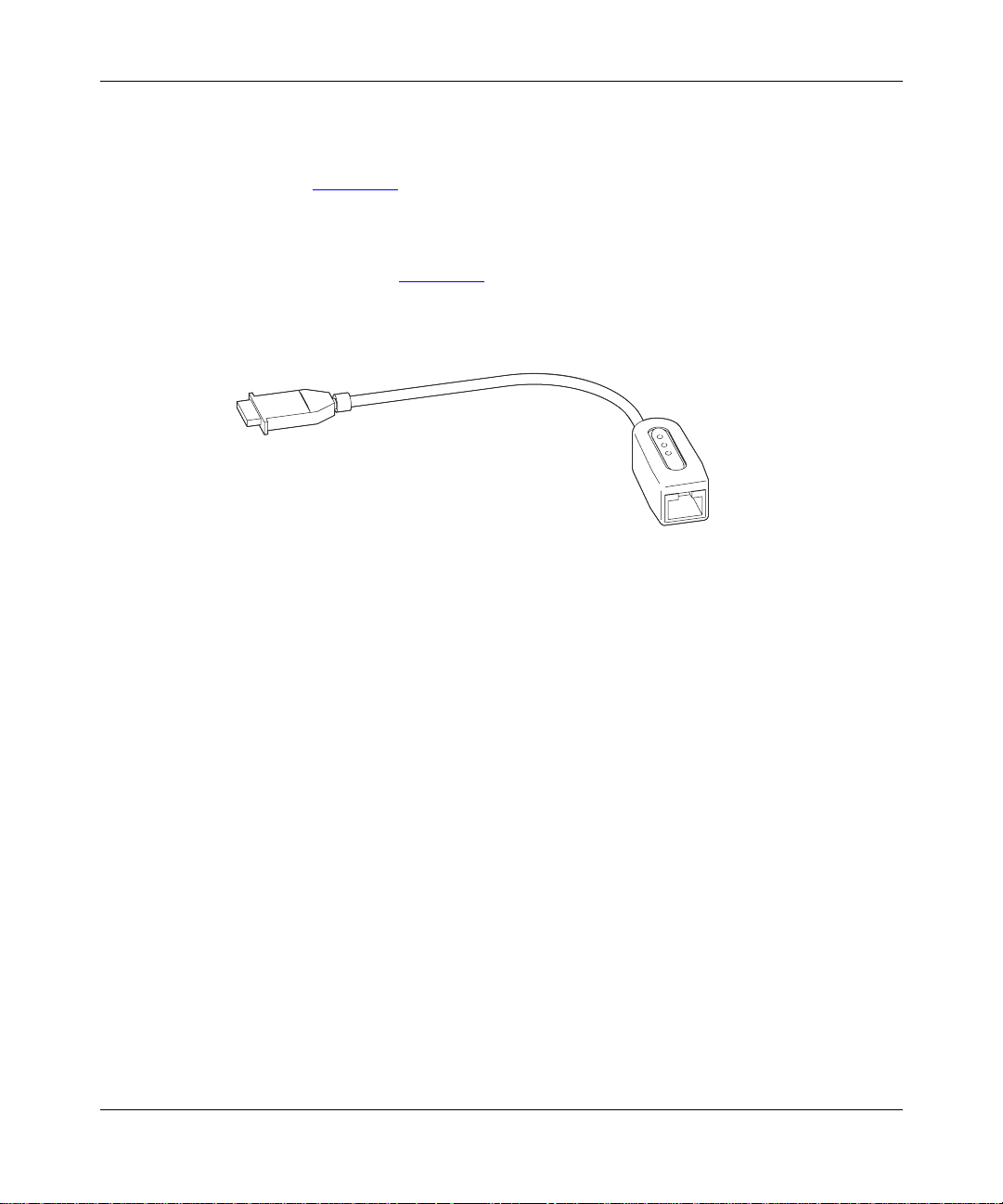
Media Coupler
The media coupler (Figure 1-2
) provides connec tion to the BayStack 22 PC Card
Adopter and to Ethernet network devices. Three LEDs located on the media
coupler indic ate 10 Mb/s or 100 Mb/s transmis sion speed and connection stability.
9476FA
Figure 1-2. Media Coupler
The 15-slot connector on the media coupler attaches to the 15-pin connector on
the BayStack 22 PC Card Ado pter. The other e nd of the medi a coupl er cont ains a n
RJ-45 port. You can attach a standard Ethernet cable to the RJ-45 port to connect
the network card to a network device such as a hub or switch.
RJ-45 Ethernet Port
The RJ-45 10BASE- T/100BASE-TX Ethernet port adapts to the correct network
speed of 10 Mb/s or 100 Mb/s t hro ugh autone goti ation wit h the bo ard c omponents
of the network card. The port is wired as an MDI-X port to connect to other
devices without using a crossover cable.
206380-A
1-3
Page 20
Installation and Reference for the BayStack 22 PC Card Adapter
9478FA
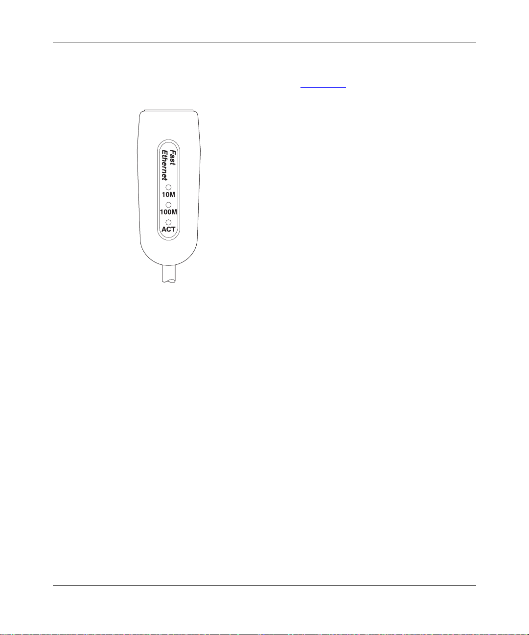
LEDs
The media coupler contains thr ee LEDs (Figure 1-3).
Figure 1-3. LEDs
The 10 Mb/s and 100 Mb/s Li nk LEDs indicate succ essful ne two rk connection s to
Ethernet and Fast Etherne t devices, respectively . The Link LEDs remain steady if
the connection is stable. You should check the RJ-45 connection if the LED is not
steady. The Activity LED indicates that network traffic is passing through the
port.
1-4
206380-A
Page 21

Table 1-1 describes the Link and Activity LED indications.
Table 1-1. LED Indica tio ns
Label Color Activity Description
10M Green On A 10 Mb/s connection has been established.
Off Power is not supplied to th e network card, or a 10 Mb/s
connection i s not est ablished.
100M Green On A 100 Mb/s connection has been established.
Off Power is not supplied to a network card, or a 100 Mb/s
connection i s not est ablished.
ACT Gre en On Heavy network traffic is passing through the port.
Green Blinking Network traf fi c is passing through the connected port.
The rate of bl inking is proportional to the amount of
netwo rk traffic.
System Requirements
Introduction
Laptop computers using the BaySta ck 22 PC Card Adopter must meet the
following r equirements:
• A laptop computer that is IBM compatible and includes:
— A 386SX or faster process or
— At least one Type II PC Card socke t
— Card Services and Socket Services compliant with PCMCIA Release 2.1
• Micros oft Windows 95, Windows 98, or Windo ws NT, including an operating
system as described in “
Operating Environments.”
• 100BASE-TX Fast Ethernet or 10B ASE-T Ethe rnet conne cti vity to your local
area network (LAN)
206380-A
1-5
Page 22

Installation and Reference for the BayStack 22 PC Card Adapter
Operating Environments
The BayStack 22 PC Card Adopter supports the foll owing operating systems:
• Microsoft Windows NT 3.51, 4.0
• Micros oft Windows 95, Windows 98
• Micros oft LAN Manager 2.x
• Micros oft Windows for Workgroups 3.11
• Microsoft Windows 3.1
• Novell NetWare 3.x, 4.x
• Lantastic 6.0
• IBM OS/2 Warp V ersion 3
Cable Requirements
You can use Category 5 (Cat 5) Ethernet cables for 10 Mb/s and 100 Mb/s
network connections to the BayStack 22 PC Card Adopter.
1-6
Use the following guidelines when using Cat 5 cables:
• Maximum length between a workstati on and a hub is 100 meters (m).
• Maximum length between two hubs is 10 m.
• Maximum length between two hubs that are functioning as Ethernet Class 2
repeaters is 100 m.
• Maximum total length between two workstations is 205 m.
Fast Etherne t C ab l es (100 Mb/s )
You must use a Cat 5 st raight-t hrough c able wit h one RJ-45 c onnector on each end
for 100 Mb/s Ethernet connections. Do not use a crossover cable.
Ethernet Cables (10 Mb/s)
You can use Cat 3, Cat 4, or Cat 5 unshielded twisted pair (UTP) cable or an
EIA/TIA-568 100-ohm shielded twisted pair (STP) cable for 10 Mb/s Ethernet
connections. You must use a straight-through cabl e with an RJ-45 connector on
each end. Do not use a crossover cable.
206380-A
Page 23
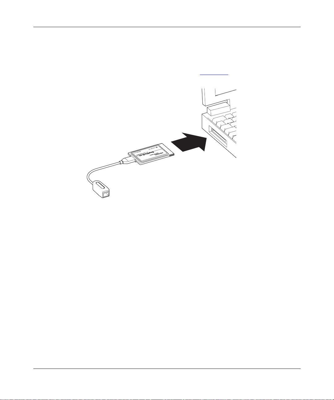
Typical Applications
The BayStack 22 PC Card Adopter provides you with ne twork connectivity to
your laptop computer. Attach the media coupler to the networ k car d; then insert
the network card into your la ptop computer (Figure 1-4).
Introduction
206380-A
9477FA
Figure 1-4. BayStack 22 Network Card Installation
1-7
Page 24
Installation and Reference for the BayStack 22 PC Card Adapter
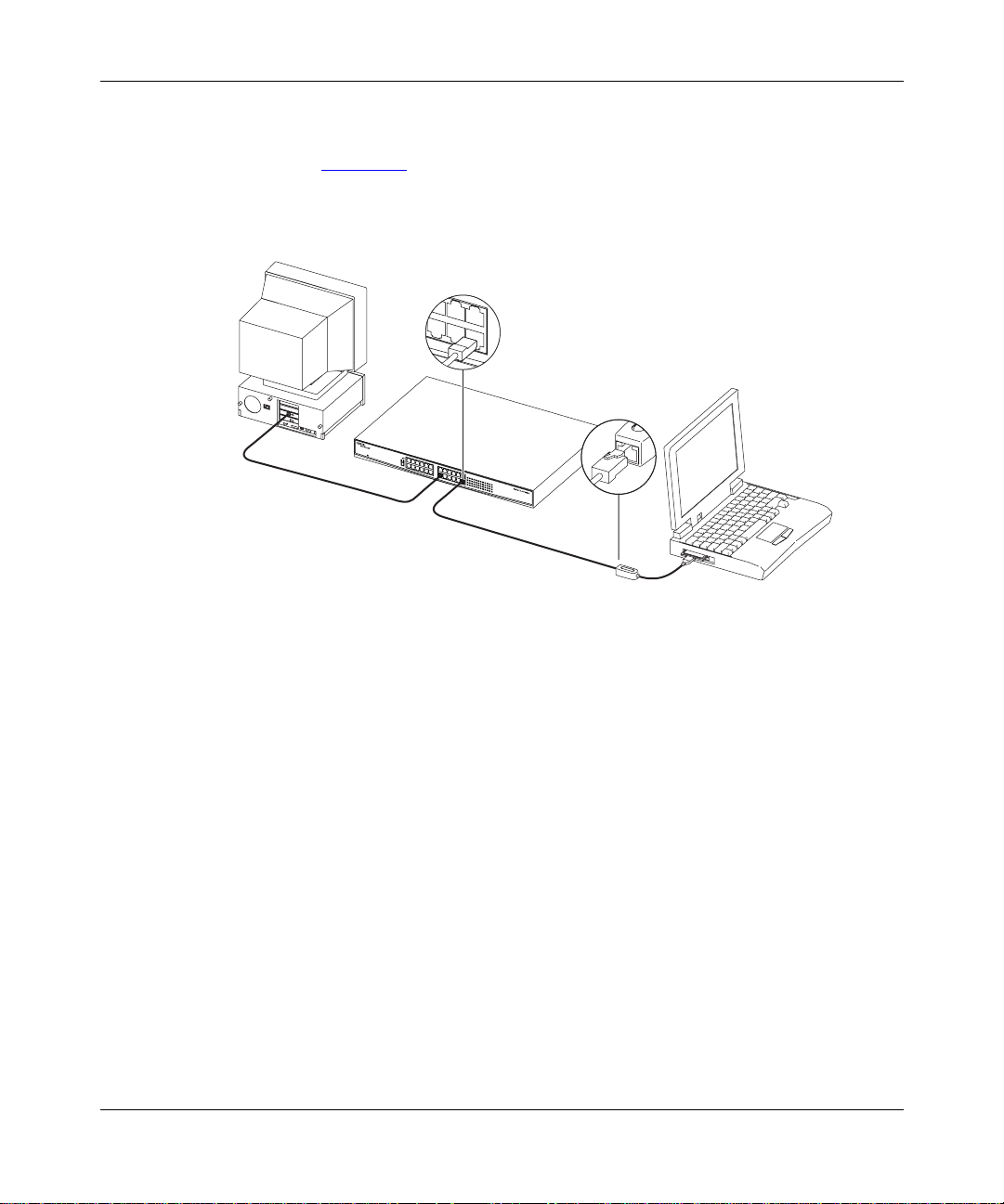
Use standard Ethernet cable s to con nect network devices, such as hubs, to the
media coupler. You can then attach other devices to the hub to share network
resources. Figure 1-5
provides an e xample of a laptop computer attached to a
BayStack 60-24T 10/100 Ethernet Hub. You can attach the hub to other
workstations, printers, servers, and additional laptop computers.
9479FA
1-8
Figure 1-5. Typical Application
206380-A
Page 25

Chapter 2
Hardware Installation
This chapter describes how to inst all the components of the BayStack 22 PC Card
Adapter in a portable (laptop) computer. Instructions for connecting the installed
network card to the networ k are provided.
You must connect all of the hardware, as described in this chapte r,
Note:
before installing the driver.
P ackage Contents
The BayStack 22 network card package contains the following:
• BayStack 22 PC Card Adapter, including plastic protector case
• Media couple r, with cable
• BayStack 22 PCMCIA Card Adapter Software & Documentation CD,
including technic al documentation in PDF format
• Safety card
• Warranty/Registration card
206380-A
2-1
Page 26

Installation and Reference for the BayStack 22 PC Card Adapter
Installing the BayStack 22 PC Card Adapter
This section p rovi des inst ructi ons for ins ta lling the BaySta ck 22 netw or k card i nto
a laptop computer. Computers vary in design; therefore, instructions and
illustrati ons in this section may not exactly match your computer. However, the
procedures will be simila r.
To install the BayStack 22 network card in a computer:
Shut down the comp ut er.
1.
Unplug the computer power cord from the power source.
2.
Depress both sides of the 15- slot connector of the media coupler.
3.
Connect the media coupler to the network card.
4.
Be sure the media cou pl er co n nec to r cl icks sec urely into pl ace.
5.
Insert the BayStack 22 network card into an empty CardBus PC Card
6.
slot on the laptop. The BayStack 22 network card label must be facing up
(Figure 2-1
).
2-2
Figure 2-1. BayStack 22 Network Card Installation
Be sure the network card is firmly secured.
7.
9477FA
206380-A
Page 27

Hardware Installation
Connect the RJ-45 connector of a standard Ethernet cable to the RJ-45
8.
port on the media coupler.
Be sure to follow the cable guidelines described in “Cable Requirements
page 1-6.
Connect the other end of the Ethernet cable to a network device, such as
9.
a hub or switch.
Attach a power cord to your laptop. Plug the cord into a power source.
10.
Turn on power to the laptop.
11.
Be sure any connected devices are receiving power.
12.
Removin g t h e BayS t ack 22 PC C a rd Adapte r
You can easily remove the BaySta ck 22 network card from your laptop computer,
if needed. Before you remove the network card you must stop the PCMCIA Card
Service.
Warning:
before stopping the PCMCIA Card Service . Your laptop will freeze if you
remove the net work card incorrectly.
To remove the BayStack 22 network card:
Do not remove the BayStack 22 network card from your laptop
” on
206380-A
From the Windows t askbar, choose Start > Settings > Control Panel.
1.
Double-click PC Card (PCMCIA).
2.
Select “Nortel Networks BayStack 22 PCMCIA card.”
3.
Click Stop.
4.
An “It is ok to remove the PCMCIA card” message is displayed.
Firmly grasp the network card and remove it from the computer.
5.
Depress both sides of the 15- slot connector of the media coupler.
6.
Remove the media coupler from the network card.
7.
2-3
Page 28

Page 29

Chapter 3
Software Installation
This chapter provide s instructions for installing the BayStack 22 network driver
software and configuring the BayStack 22 PC Card Adapter on your network.
Drive rs compatible with se veral operating system s are located on the BayStac k 22
PCMCIA Card Adapter Software & Documentation CD. You can install specific
driv ers for Windows 95, Wind o ws 98, W indows NT, No v ell NetWare 4.x, or other
systems.
This guide provides instructions for installing the drivers for Windows 95,
Wind ows 98, Windows NT, and Novell NetWare 4.x. You can read the
RELEASE.txt file in the BayStack 22 PCMCIA Card Adapter Software &
Documentation CD for instructions to install drivers for other operating systems.
206380-A
Different versions of Windo ws operating systems may have different installation
screens than those shown in these instructions. Your installation screens may
appear in a different order than those in this chapter . You will be prompted for th e
same information, regardless of the Windo ws version.
The BayStack 22 network card is automatically detected by Wind ows 95 and
Wind ows 98. Follow the instructions during this automatic installation process.
You will be prompted to insert the Bay Stack 22 PCMCIA Card Adapter Software
& Documentation CD into your laptop computer during the installation.
The driver must be manually installed for Windows NT.
The BayStack 22 PC Card Adapter may also be referred to as a
Note:
PCMCIA Ethernet adapter or controller.
3-1
Page 30

Installation and Reference for the BayStack 22 PC Card Adapter
Select which driver you want to install for your new hardware:
Preinstallation
Perform the following tasks prior to installing the BayStack 22 network driver:
• Inst all the BayStack 22 network card before installing the BayStack 22
network driver.
• Remove all other network cards from the laptop computer. If you have other
network cards or adapter s installed in your computer, the driver installation
process will not ex ecute. You do not need to uninstall other networ k driver
software before you run the installation.
• Be sure to ha ve the Windows 95 or W indows 98 CD and the BayStack 22
network driver CD ready to use during the inst allation. You may be prompted
to install either CD. You may receive the “Insert Disk” and “Please insert the
disk labeled Windows...” messages. If you rece ive these messages, insert the
appropriate C D, e nter the appropriate drive letter a nd CD name, and click OK
to continue the installation. For example, if drive D is your CD drive and you
insert the Windows 95 CD, enter d:\win95 when prompted.
Installing the Network Driver in a Windows 95 Environment
3-2
This section describes the steps required to install the driver software in a
Wind ows 95 environment.
To install the dri ver:
Turn on the power to the computer, and start Windows 95.
1.
A generic New Hardwa re Found window opens (Figure 3-1
New Hardware Found
PCMCIA Ethernet PCMCIA Adapter
Figure 3-1. New Hardware Found Window —Generic
).
9561DA
206380-A
Page 31

Software In stallatio n
A second New Hardwa re Foun d window ope ns, iden tifying your BayStack 22
PC Card Adap ter (Figure 3-2).
New Hardware Found
Nortel BAYSTACK 22 PCMCIA Ethernet
Select which driver you want to install for your new hardware:
9495DB
Figure 3-2. New Hardware Foun d Wi ndow—BayStack 22
Network Card
The Update Device Driver Wizard dialog box opens (Figure 3-3).
206380-A
Figure 3-3. Update Device Driver Wizard Dialog Box
Inse r t the
2.
CD into the CD drive as prompted
BayStack 22 PCMCIA Card Adapter Software & Docu mentation
.
3-3
Page 32

Installation and Reference for the BayStack 22 PC Card Adapter
Click Next.
3.
The Copying Files dialog box opens (Figure 3-4
Copying Files...
The file ndishlp.sys on Windows 95 CD-ROM
could not be found.
Insert Windows 95 CD-ROM into the drive
selected below, and click OK.
Copy files from:
D:\Win95
).
OK
Cancel
Skip File
Details...
8528DD
Figure 3-4. Copying Files Dialog Box
Insert the Windows 95 CD as in dica te d.
4.
The next Update Device Driver Wizard dialog box (Figure 3-5
that the new BayStack 22 network card has been found and the driver is
automatically loa ded.
Update Device Driver Wizard
Windows found the following updated driver for this
device:
Nortel Baystack 22 10/100 Mbps Fast Ethernet
PCMCIA Adapter
If you want to use this driver, click Finish. If this is not the
correct driver and you want to search for a different driver
manually, click Other Locations.
) indicates
3-4
Location of Driver
Other Locations...
< Back
Finish Cancel
8527DD
Figure 3-5. Update Device Driver Wizard Dialog Box —BayStack 22
Network Card
206380-A
Page 33

Software In stallatio n
Click Finish.
5.
Another Copying Files dia log box opens.
Click OK.
6.
The System Settings Change dialog box opens (Figure 3-6
Figure 3-6. System Settings Change Dialog Box
Remove all CDs fr om the CD driv e.
7.
Click Yes.
8.
).
Restarting your system is necessary to enable your PC to finish setting up
your new hardw are.
206380-A
3-5
Page 34

Installation and Reference for the BayStack 22 PC Card Adapter
Configuring the Windows 95 Environment
This section provides instructions for configuring the BayStack 22 network card
on the network after you have installed the BayStack 22 network driver on your
Wind ows 95 laptop computer.
To configure the network properties for your laptop:
From the Windows t askbar, choose Start > Settings > Control Panel.
1.
Double-click Network.
2.
The Network dialog box opens. The configuration tab is displayed by default
(Figure 3-7
).
3-6
Figure 3-7. Network Dialog Box—Configuration Ta b
206380-A
Page 35

Software In stallatio n
Select Properti es .
3.
The Properties dialog box open s. The Advanced tab is displayed by default
(Figure 3-8
).
206380-A
Figure 3-8. Properties Dialog Box
In the Property list , se lect Connection Type.
4.
The AutoSense value is displayed by default.
In the Value list, select from the following connection speed types:
5.
• AutoSense (Use this setting if you want the RJ-45 port on the media
coupler to use the faste st speed supported by the attached device.)
• 100BASE-TX for 100 Mb/s connections
• 100BASE-TX or 10BASE-T full-duplex mode, for 10 and 100 Mb/s
switch connections
• 10BASE-T twisted pair for 10 Mb/s connections
3-7
Page 36

Installation and Reference for the BayStack 22 PC Card Adapter
Click OK.
6.
The Properties Dialog Box opens ag ain (Figure 3-8
Click the Reso urce s tab.
7.
The Resources dialog box opens (Figure 3-9
).
).
3-8
Figure 3-9. Resources Dialog Box
Enter the Co nfigurati o n type, interru pt (IR Q) num b er, and I/O address
8.
range, or accept the default settings.
Click OK.
9.
Return to the Network Dialog Box > Configuration tab (Figur e3-7).
10.
Click Add.
11.
206380-A
Page 37

Software In stallatio n
Select TCP/IP.
12.
The Select Network Component Type dialog box (Figure 3-10
Figure 3-10. Select Network Component Type Dialog Box
Select Protocol.
13.
Click Add.
14.
The Select Network Protocol dialog box opens (Figure 3-11
) opens.
).
206380-A
Figure 3-11. Select Network Protocol Dialog Box
In the Manufacturers list , select Microsoft.
15.
3-9
Page 38

Installation and Reference for the BayStack 22 PC Card Adapter
In the Network Protocols list, select TCP/IP.
16.
Click OK.
17.
Return to the Con figurati o n tab.
18.
Select Properti es .
19.
The TCP/IP Properties dialog box ope ns (Figur e 3-12
).
3-10
Figure 3-12. TCP/IP Properties Dialog Box
Select the IP Address tab.
20.
If the computer has a static IP address, sp ecify the IP address, subnet
21.
mask, and default gateway of your computer.
You can also choose the “Obtain an IP address automatically” option if the
computer does not hav e a static IP address. If you choose this option your
IP address will be supplied by DHCP.
206380-A
Page 39

Software In stallatio n
Use the Gateway or DNS Configuration tabs to configure other
22.
parameters, as needed.
Click OK.
23.
The Copying Files dialog box is displa yed.
In the “Copy files from:” field, enter the location of the requested files or
24.
CD.
Click OK.
25.
The system restart dialog box opens. Restarting your system is necessary to
enable your PC to finish se tting up your new hardware.
Remove the CD from the CD drive.
26.
Click Yes.
27.
Your system restarts.
Installing the Network Driver in a Windows 98 Environment
This section describes the steps required to install the driver software in a
Wind ows 98 environment.
To install the network driver:
Turn on the power to the computer, and start Windows 98.
1.
The New Hardware Found window opens, identi fying a gener ic netw ork card.
For instance, the window may list “PCMCIA Ethernet Adapter, or PCMCIA
Ethernet Controlle r” (Figure 3-13
New Hardware Found
PCMCIA Ethernet PCMCIA Adapter
Select which driver you want to install for your new hardware:
Figure 3-13. N ew Hardware Found Window—Gener ic
).
9561DA
206380-A
3-11
Page 40

Installation and Reference for the BayStack 22 PC Card Adapter
Select which driver you want to install for your new hardware:
A second New Hardwa re Foun d window ope ns, iden tifying your BayStack 22
PC Card Adap ter (Figure 3-14).
New Hardware Found
Nortel BAYSTACK 22 PCMCIA Ethernet
Figure 3-14. New Hardware Foun d Wi ndow—BayStack 22
Network Card
The Add New Hardware Wizard dia log b ox o pen s (Figure 3-15).
9495DB
Figure 3-15. Add New Hardware Wizard Dialog Box
3-12
206380-A
Page 41

Software In stallatio n
Click Next.
2.
The Add New Hardware Wizard—Driver Sele cti on d ialog b ox op en s
(Figure 3-16
).
206380-A
Figure 3-16. Add New Hardware Wiz ard—Driver Sele ction Dialog Box
3-13
Page 42

Installation and Reference for the BayStack 22 PC Card Adapter
Click Next.
3.
The Add New Hardware Wizard—Driver Location dialog box opens
(Figure 3-17
).
3-14
Figure 3-17. Add New Hardware Wiz ard—Driver Locati on Dialog Box
Insert the
4.
BayStack 22 PCMCIA Card Adapter Software & Docu mentation
CD into your CD drive.
Select CD-ROM dri ve.
5.
206380-A
Page 43

Software In stallatio n
Click Next.
6.
The Add New Hardware Wizard—Driver Search dialog box opens
(Figure 3-18
).
206380-A
Figure 3-18. Add New Hardware Wizard—Driver Search Dialog Box
Click Next.
7.
The Insert Disk message is displaye d (Figure 3-19
Figure 3-19. Insert Disk Message
).
3-15
Page 44

Installation and Reference for the BayStack 22 PC Card Adapter
Click OK.
8.
The Copying Files dialog box opens (Figure 3-20
Figure 3-20. Copying Files Dialog Box
Insert your Windows 98 CD into the CD drive of your laptop.
9.
Specify the letter o f your CD drive an d your Windows 98 C D.
10.
For instance, if drive F is your CD drive, enter
).
F:\WIN98
.
3-16
206380-A
Page 45

Software In stallatio n
Click OK.
11.
The Add New Hardware Wizard—Installation Finished dialog box opens
(Figure 3-21
).
206380-A
Figure 3-21. Add New Hardware Wiz ard—Installation Finished Dialog
Box
Click Finish.
12.
The System Settings Change dialog box opens (Figure 3-22
Figure 3-22. System Settings Change Dialog Box
).
Restarting your system is necessary to enable your PC to finish setting up
your new hardw are .
3-17
Page 46

Installation and Reference for the BayStack 22 PC Card Adapter
Remove the CD from the CD drive.
13.
Click Yes.
14.
Your system restarts.
Configuring the Windows 98 Environment
You must configure your laptop computer on the network after installing the
BayStack 22 network driver on your Windows 98 laptop computer.
To configure the network properties for your laptop:
From the Windows t askbar, choose Start > Settings > Control Panel.
1.
Double-click Network.
2.
The Network dialog box opens. The TCP/IP network protocol for the
BayStack 22 network driver is already installed.
The configur ation tab (Figure 3-23
) is displayed by default.
3-18
Figure 3-23. Network Dialog Box—Configuration Ta b
206380-A
Page 47

Software In stallatio n
Select Nortel Ba yStack 22 10/100 Mbps Fast Ethernet Adapter.
3.
Click Properti es .
4.
The BayStack 22 network driver dialog box opens (Figure 3-24
).
206380-A
Figure 3-24. BayStack 22 Network Driver Dialog Box—Advanced Tab
Select the Advanced tab.
5.
In the Property list , se lect Connection Type.
6.
In the Value list, select one of the following:
7.
• AutoSense—Select the default AutoSense setting if you want the port to
use the fastest speed supported by the attached device.
• 10BaseT (Twisted Pair)—Use this settin g for 10 Mb/s Ethern et hubs.
• 100BaseTx—Use this setting for 100 Mb/s Ethernet hubs.
• 100BaseTx or 10BaseT full duplex—Use the se settings for 100 Mb/s and
10 Mb/s Ethernet switches.
3-19
Page 48

Installation and Reference for the BayStack 22 PC Card Adapter
Click OK.
8.
Return to the Network dialog box (Figure 3-23).
9.
Select the Access Control tab (Figure 3-25).
10.
3-20
Figure 3-25. Access Control T ab
Select Share-level access control.
11.
Click OK.
12.
The system restart dialog box opens.
Remove all CDs fr om the CD driv e.
13.
Click Yes.
14.
Your system restarts.
206380-A
Page 49

Configuring the Interrupt Request
You can configure the Interrupt Request ( IRQ) par ameters. Nortel Networks
recommends conf iguring the IRQ only if you are an expert at network or
PC configuration.
To configure the IRQ:
From the Windows t askbar, choose Start > Settings > Control Panel.
1.
Double-click System.
2.
Select the Reso u rces tab (Figure 3-26).
3.
Software In stallatio n
206380-A
Figure 3-26. Resources Tab
Clear the “Use automatic settings” box.
4.
In the Resource type list, select Interrupt Req ue st .
5.
3-21
Page 50

Installation and Reference for the BayStack 22 PC Card Adapter
Click Change Setting.
6.
The Edit Interrupt Request dialog box opens (Figure 3-27
Figure 3-27. Edit Interrupt Request Dialog Box
).
3-22
Use the arrows next to the Value field to select an IR Q val ue.
7.
Click OK.
8.
The Resources tab is displayed ag ain. The new IRQ setting is displayed also.
Click OK.
9.
The “Create a Forced Conf iguration” message is displayed.
Click Yes.
10.
Insert the Windows 98 CD into the CD drive of your laptop.
11.
206380-A
Page 51

Software In stallatio n
Installing the Network Driver in a Windows NT 4.0 Environment
This section describe s the steps requir ed to insta ll the netwo rk dri v er soft war e in a
Wind ows NT 4.0 environment.
To install the network driver in a laptop computer:
Be sure that the standard network services are installed on the
1.
Windows NT 4.0 laptop.
From the Windows t askbar, choose Start > Settings > Control Panel.
2.
Double-click Network.
3.
The Network dialog box opens. The Identification tab is displayed by default.
Select the Adapters tab (Figure 3-28).
4.
206380-A
Figure 3-28. Network Dialog Box—Adapters Tab
3-23
Page 52

Installation and Reference for the BayStack 22 PC Card Adapter
Click Add.
5.
The Select Network Adapter dialog box opens (Figure 3-29
Figure 3-29. Select Network Adapter Dialog Box
Click Have Disk.
6.
Place the
7.
BayStack 22 PCMCIA Card Adapter Software & Documentation
CD into the CD drive of your compute r.
).
3-24
The Insert Disk dialog box opens (Figure 3-30
Figure 3-30. Insert Disk Dialog Box
).
206380-A
Page 53

Software In stallatio n
Specify the letter o f the dr ive into w hi ch you insta lled the C D.
8.
Typically the CD drive is letter D.
Click OK.
9.
The Select OEM Option dialog box (Figure 3-31
Figure 3-31. Select OEM Option Dialog Box
Select the BayStack 22 PC Card Adapter.
10.
) opens.
206380-A
3-25
Page 54

Installation and Reference for the BayStack 22 PC Card Adapter
Click OK.
11.
The Windows NT Configuration dialog box opens (Figure 3-32
Figure 3-32 . Wi ndows NT Confi gu ra ti on D i a lo g Box
).
Set the follo wing con figuration parameters, or accept the default settings:
• IRQ le vel—Interrupt request le vel. IRQ Level 3 is the default.
• I/O Port Addr ess—Input /Output memory addres s for the lapto p compu ter.
The BayStack 22 network driver installation for Windows NT does not
automatically specifyn this address. You must configure it manually.
• Connect ion Type—Select one of the following settings:
— AutoSense—Select the default AutoSense settin g if you wa nt the port
to use the fastest speed supported by the attached device.
3-26
— 100 or 10 half-duplex mode—Use these settings for 100 Mb/s and
10 Mb/s Ethernet hubs.
— 100 or 10 half- or full-duplex mode—Use these settings for 100 Mb/ s
and 10 Mb/s Ethernet switches.
206380-A
Page 55

Configuring the Windows NT Environment
This section provides instructions for configuring the BayStack 22 network card
on the network after you have installed the BayStack 22 network driver on a
Windows NT laptop computer.
To configure the network properties for your Windows NT laptop:
From the Windows t askbar, choose Start > Settings > Control Panel.
1.
Double-click Network.
2.
The Identification tab is displayed by default.
Select the Bin di ngs tab (Figure 3-33).
3.
Software In stallatio n
206380-A
Figure 3-33. Bindings Tab
The all services selection is the default.
3-27
Page 56

Installation and Reference for the BayStack 22 PC Card Adapter
Select all adapters (Figure 3-34).
4.
3-28
Figure 3-34. Bindings Tab—All Adapters Selection
All of the adapters installed in your computer display.
Verify that the BayStack 22 PC Card Adapter is displayed and selected.
5.
Click OK.
6.
The Network dialog box is displayed again.
206380-A
Page 57

Software In stallatio n
Select the IP address tab (Figure 3-35).
7.
206380-A
Figure 3-35. IP Address Tab
If the computer has a static IP address, sp ecify the IP address, subnet
8.
mask, and default gateway of your computer.
You can also choose the “Obtain an IP address from a DHCP server” option if
the computer does not have a static IP address.
Click OK.
9.
3-29
Page 58

Installation and Reference for the BayStack 22 PC Card Adapter
Select the DNS tab (Figure 3-36) to configure point-to-point parameters if
10.
you ar e using an Internet service provider (ISP).
3-30
Figure 3-36. DNS T ab
Enter the host name and domain of your computer.
11.
Enter the DNS service and domain suffix search order information for
12.
your ISP.
Click OK.
13.
206380-A
Page 59

Software In stallatio n
Select the WINS Address tab (Figure 3-37).
14.
206380-A
Figure 3-37. WINS Address Tab
Enter the IP address of your primary and secondary WINS servers.
15.
Click OK.
16.
Restart your system if prompted.
17.
3-31
Page 60

Installation and Reference for the BayStack 22 PC Card Adapter
Installing the Net work Driver in a Novell NetWare 4.x Environment
This section describes the steps required to install the BayStack 22 network dr iver
software in a Novell NetWa re version 4.x environment. You must install and
configure the software on your Novell server and cli ent. Your laptop computer is
considered the client.
If you are install ing the BayStack 22 ne twork dr i ve r software in a Novell NetWare
version 3.12 environment, refer to the Readme.txt file on the BayStack 22
PCMCIA Card Adapter Software & Documentation CD.
Installing the Network Card in a Novell NetWare Server
This section describes the steps required to install the BayStack 22 network dr iver
software in your Novell NetWare 4.x server .
Your laptop computer must have the following installed prior to installing the
BayStack 22 network driver software:
• BayStack 22 PC Card Ad ap ter
3-32
• MS-DOS operati ng system
• Novell NetWare 4.x se rver soft wa re
To install the BayStack 22 network driver in your Novell NetWare 4.x server:
Insert the
1.
CD into the CD drive of your server.
Verify that the following files are located in the Novell NetWare server
2.
directory.
• \NETWARE\SERVER\4.X\MSM.NLM
• \NETWARE\SERVER\ETHERTSM.NLM
If the files listed in step 2 are not located in the server directory, copy
3.
these file s from the
Documentation
BayStack 22 PCMCIA Card Adapter Software & Docu mentation
BayStack 22 PCMCIA Card Adapter Software &
CD.
206380-A
Page 61

Software In stallatio n
Copy the following file from the
4.
Software & Documentation
BayStack 22 PCMCIA Card Adapter
CD to the root directory .
• \ENABLER\B22ENA10.EXE
You can also run the BS22ENA10.EXE program from the BayStack 22
PCMCIA Card Adapter Software & Documentation CD instead of copying
the program to your root directory.
Access a DOS prom pt s creen.
5.
From the DOS prompt you must run the BS22ENA10.EXE program before
installing the BaySta ck 22 network driver.
Enter the following syntax:
6.
B22ENA10 [/IRQ:x][/IOP:xxx]
where:
• IRQ is the inter rupt number used specifically for the BayStack 22
network card. This number must not be used b y any other device in the
system. The default IRQ value is 3.
• IOP is the star ting Input/Output (I/O) port address, in hexadecimal
format. The BayStack 22 network card requires 32 consecutive free
I/O port addresses. The default IOP value is 0x300.
206380-A
For example, the following command enables a BayStack 22 network card
having an IRQ v al ue of 5 and an IOP value of 300:
B22ENA10 /IRQ:5 /IOP:300
Change to the Novell NetWare server directory.
7.
For instance, type the command:
CD\NWSERVER
Type:
8.
SERVER
Press Enter.
9.
At the server prompt, enter:
10.
LOAD INSTALL
The NetWare Server Installation Utility loads.
From the Installation Options menu, select Driver options.
11.
3-33
Page 62

Installation and Reference for the BayStack 22 PC Card Adapter
Press Enter.
12.
From the Driver Optio ns m en u, s elect Configure network drivers .
13.
Press Enter.
14.
From the Additional Driver Actions menu, select Select a driver.
15.
Press Enter.
16.
Press Insert (<IN S >) to ins ta ll an unlisted driver.
17.
By default, your a: drive is scanned.
Press <F3> to specify another path or drive.
18.
Specify the directory on the
19.
& Documentation
For example , type
Insert the
20.
BayStack 22 PCMCIA Card Adapter Software & Docu mentation
CD where the Novell NetWare drivers are located.
D:\NETWARE\SERVER
BayStack 22 PCMCIA Card A dapter Software
.
CD in the CD drive of your server.
Press Enter.
21.
The followi ng file is automatically copied from the BayStack 22 PCMCIA
Card Adapte r Software & Documentation CD to your server:
• \NETWARE\SERVER\B22LAN10.LAN
From the Select a driver to install: menu, select Nortel 22 10/100
22.
PCMCIA Fast Ether net Adapter.
Press Enter.
23.
The “Do you want to copy driver B22LAN10.LAN (Y)(N)” message is
displayed.
Select Yes.
24.
Proceed to the next section, “Speci fyi ng Driver Para m e ter s ” on
25.
page 3-35, if you want to specify driver paramete rs or complete the
following 3 steps.
3-34
Type:
26.
down
The server closes.
206380-A
Page 63

Software In stallatio n
Type:
27.
exit
Your system returns to the DOS prompt.
In the DOS prompt, type:
28.
server
The BayStack 22 network card and the server on the Novell NetWare network
open and are functioning.
Note:
Each time you reboot your serve r, you must run the B22ENA10.E XE
program to enable the BayStack 22 network card.
Specifying Driver Parameters
The BayStack 22 network driver installs with default pa rameters. You can set
specific driver parameters for the driver if you do not want to use the default
settings.
206380-A
To set specific driver parameters:
From the Board BayStack 22 (Driver B22LAN10) Actions menu, select
1.
“Select/Modify driver parameters and protocols.”
Press Enter.
2.
The default protoc ol is IPX. You can also select TCP/IP or AppleTalk.
Select a protocol from the available options.
3.
Specify the slot number (slot#).
4.
Select “Save parameter and load select driver.”
5.
If you select the IPX protocol, the network number (network #) is randomly
generated.
Press Enter at each of the following four prompts :
6.
• 802.3
• 802.2
•SNAP
• Etherne t II
3-35
Page 64

Installation and Reference for the BayStack 22 PC Card Adapter
Type:
7.
down
The server closes.
Type:
8.
exit
Your system returns to the DOS prompt.
In the DOS prompt, type:
9.
server
The BayStack 22 network card and the server on the Novell NetWare network
open and are functioning.
Note:
Each time you reboot your serve r, you must run the B22ENA10.E XE
program to enable the BayStack 22 network card.
Installing the Network Card in a Novell NetWare Client
3-36
This section describes the steps required to install the BayStack 22 network dr iver
software on your Novell NetWa re 4.x laptop computer, or client. You must have
already installe d a BayStack 22 PC Card Adapter in your lapt op.
To install the BayStack 22 network driver on your Novell NetWare 4.x client:
Verify that your BaySta c k 22 network card is properly installe d in your
1.
Novell NetWare 4.x laptop.
Insert the
2.
BayStack 22 PCMCIA Card Adapter Software & Docu mentation
CD into your laptop.
Access a DOS prom pt s creen.
3.
From the DOS prompt you must run the BS22ENA10.EXE program before
installing the BaySta ck 22 network driver.
206380-A
Page 65

Software In stallatio n
Enter the following syntax:
4.
B22ENA10 [/IRQ:x][/IOP:xxx]
where:
• IRQ is the inter rupt number used specifically for the BayStack 22
network card. This number must not be used b y any other device in
the system. The default IRQ value is 3.
• IOP is the star ting input/output (I/O) port address, in hexidecimal
format. The BayStack 22 network card requires 32 consecutive free
I/O port addresses. The default IOP value is 0x300.
For example, the following command enables a BayStack 22 network card
having an IRQ v al ue of 5 and an IOP value of 300:
B22ENA10 /IRQ:5 /IOP:300
Note:
If you installed th e EMM386.EXE program in CONFI G. SYS, you must
exclude the memory address range D000 to DFFF or D400 to D7FF in the
EMM386.EXE program. The B22ENA10. EXE prog ram uses this memory
address range to rea d conf igur ation infor mation from th e BayStack 22 ne twork
card.
For example , the following commands exclude the required memory addr ess
range:
DEVICE=EMM386.EXE NOEMS X=D400-D7FF
DEVICE=EMM386.EXE NOEMS X=D000-DFFF
206380-A
Access the Novell NetWare client directory on y our client laptop.
5.
From the \NETWARE \DOSOD I directory on the
6.
Card Adapter Software & Documentation
LSL.COM
B22ODI10.COM
IPXODI.COM
NETX.EXE
NET.CFG
CD, copy the following files:
BayStack 22 PCMCIA
The STARNET.BAT file in the \NETWARE\DOSODI directory ex ecute s the
first four files automatically, in the correct sequence. Refer to “C lient Files”
on page B-4
for descriptions of these files.
3-37
Page 66

Installation and Reference for the BayStack 22 PC Card Adapter
Press Enter.
7.
You can now log in to your network.
8.
Edit the
NET.CFG
file to specify driver parameters, as needed.
You can specify the PORT, IRQ, NWAY, and S10/S10FD/S100/S100FD
parameters.
Refer to Appendix B, “
Novell NetWare Reference In form a tion, ” for sa mp le
NET.C FG files.
3-38
206380-A
Page 67

This chapter provides seve ral methods for trouble shooting problems related to the
BayStack 2 2 PC Card A dap t er.
Diagnostic LEDs
Three LEDs on the media coupler of the BayStack 22 network card provide
diagnostic infor mation. The 10 and 100 Mb/s Link LEDs indicate success ful
network connectio ns to Ether net and F ast Ethe rnet de vi ces, respec ti ve ly. The Link
LEDs remain steady if the connection is stable. You should check the RJ-45
connection if the LED is not steady. The Activity LED indicates acti ve network
traffic.
Chapter 4
Troubleshooting
Table 4-1
Table 4-1. LED Indica tio ns
Label Color Activity Description
10M Green On A 10 Mb/s connection has been established.
100M Green On A 100 Mb/s connection has been established.
ACT Gre en On Heavy network traffic is passing through the port.
Green Blinking Network traf fi c is passing through the connected port.
206380-A
describes the Link and Activity LED indications.
Off Power is not supplied to th e network card, or a 10 Mb/s
connection i s not est ablished.
Off Power is not supplied to a network card, or a 100 Mb/s
connection i s not est ablished.
The rate of bl inking is proportional to the amount of
netwo rk traffic.
4-1
Page 68

Installation and Reference for the BayStack 22 PC Card Adapter
Hardware Issues
Perform the following tasks to check for hardware problems:
• Verify that you are using the correct cables and the correct cable lengths, as
described in “Cable Requirements
• Make su re the media coupler is firmly connected to the network card and to a
network device.
• Use a dif ferent port on the network device.
• Verify that the BayStack 22 network card is fully and firmly sea ted in the slot
connector in the co mputer. Check the connector edges of the card for damage.
• Replace the network card in question with a network card that you are sure
functions properly. Run generic network interface card diagnostic tests.
• Inst all the network card in question into another computer and run the tests
again.
• Remo ve all other network cards from the computer and run the tests agai n.
If the verification/diagnostic run is not normal, there is probably an interrupt
number conflict. You must manually resolve the conflict by running a CMOS
Setup utility after you have reinstalled the expansion cards.
” on page 1-6.
Software Issues
Perform the following tasks to check for software problems:
• Verify that the proper driver is loaded, as explained in Chapter 3, “
Installation. ” Be s ure y ou foll o wed the dir ections f or t he ope rating sy ste m you
are running on the computer.
• Check that the new configurations match the configurations of the network
device if you have manually configured the speed or mode of the network
card. Nortel Networks recommends setting the network card to
autonegoti ation when installing the network driver.
• Verify that the PCMCIA slot in the computer is an enabled bus-master slot.
Some computers may require that you configure the PCMCIA slot to enable
bus masterin g. Ref er to your computer manual for information about the
PCMCIA BIOS setup program.
• Verify that your BIOS software correctly supports the PCMCIA Local Bus
Specifi cation, version 2.0 or later. Upgrade your BIOS software if needed.
4-2
Software
206380-A
Page 69

Troubleshooting
• Deter mine whether or not the network card slot is deactivated at the BIOS
level. Use the CMOS Setup utility in your computer to provide the option to
activate or deactivate slots.
• Disabl e the Plug and Play option (PnP) in the BIOS setup program if it is
recommended by your PC manual. Some computers may requir e you to
perform this task. Incorrectly assigned resource s between network cards may
cause problems.
Note:
Always consult your computer manual for information about changing
motherboard jumper and BIOS settings. If you modify the BIOS settings,
make sure the jumper and BIOS settings match.
• You may need to reserve interrupts and memory addresses for installed
Industry Standard Architecture (ISA) cards to prevent PCMCIA cards from
using the same settings. Refer to your PC manual for instructions.
206380-A
4-3
Page 70

Page 71

Tables in this appendix provide technical product specifica tions and list the
ava ilable software drivers for the BayStack 22 PC Card Adapter.
Product Specifications
Table A-1 lists technical specificat ions for the BayStack 22 network card.
Table A-1. Technical Specifications
Appendix A
Technical Specifications
Standards Compatibility
EMC Compliance
CE Mark: EN50081-1
Emissions: FCC Class B
Physical Dimensions
Network Card: 86 x 54 x 5.0 mm (3.37 x 2.13 x 0.2 in)
Media Coupler: 222 mm (8.75 in) (including connectors)
Weight
Environment
Operating: 0° to 55
Humidity: 10% to 9%, noncondensing
Power Consumption
206380-A
IEEE 802.3 10BASE-T
IEEE 802.3u 100BASE-TX
PC Card 95 CardBus Standard
EN55022
IEC1000-4-2/3/4/6
VCCI Class B
EN55022 (CISPR 22) Class B
30g (1.94 oz)
°
C (32° to° 131
+5 V DC at 145mA (Standby)
+5 V DC at 300mA (Transmit)
°
F)
A-1
Page 72

Installation and Reference for the BayStack 22 PC Card Adapter
Table A-1. Technical Specifications
Network Interface
10BASE-T: RJ-45 (UTP Cable, Categories 3, 4, 5)
100BASE-TX: RJ-45 (UTP Cable, Category 5)
Data Interface
I/O Address
System Clock
Interrupt
LED Indicators
32-bit bus- ma stering PCI
Det ec ted by B IO S or Car d S erv ice
20 to 33 MHz
INT A, mapping to BIOS IRQ setup
10 Mb/s, 100 Mb/s, Activity
Software Drivers
Table A-2 lists the available software drivers for the BayStack 22 net work card.
Refer to Chapter 3, “Software Installation
Wind ows-based driv ers. Refer to the README files associated with other drivers
for installation instructions.
Table A-2. Available Software Drivers
,” for installation instructions for the
Driver Compatible Opera ting Systems
Network Devic e Int erface
Specifications (NDIS)
NetWare Open Data-Link
Interface (ODI)
Packet IFTP P C /T C P
Microsoft Windows 95, Windows 98
Microsoft Windows NT 3.51, 4.0
Microsoft Windows for Workgro ups 3.11
Microsoft LAN Manager 2. x
Banyan VINES
DEC Pathwor ks
IBM TCP/IP for DOS
LAN Support program
SUN PC-NFS
Novell Net Ware 3.x, 4.x
NetWare LAN Workplace TCP/IP
Novell LAN Analyzer for NetWare
Novell Personal NetWare
NCSA TCP/IP
A-2
206380-A
Page 73

Novell NetWare Reference Information
This appendix provide s reference files for your Novell NetWa re 4.x ope rating
system. Server and client information is provided in the following sections.
If you are installing the BaySt ack 22 PCMCIA Networ k Driver software in a
Novell NetWare version 3.12 environm ent, refer to the Readme.txt file on the
BayStack 22 PCMCIA Card Adapter Software & Documentation CD.
Novell NetWare Server Files
Appendix B
This section provides information about the Novell NetWare 4.x files in general,
and specifi cally about the AUTOEXEC.NCF file parameters.
File Descriptions
Table B-1 provides descriptions of the Nove ll NetWare server files.
Table B-1. Serv er Fi les
File Name Description
README.TXT A summary of the BayStack 22 net work driver installation for th e
B22ENA10.EXE Enabling DOS program for the BayStack 22 network driver.
B22LAN10.LAN BayStack 22 32-bit ODI server driver.
B22LAN10.LDI BayS tack 22 network driver installation information.
ETHERTSM.NLM NeWare Server 3.1X, 4.1X LAN drive r Topology Specif ic Module
3.1X\NBI31X.NLM NetWare Server 3.1X Bus Interface module.
3.1X\MSM31X.NLM NetWare Server 3.1X LAN driver Media Support Module (MSM).
4.X\MSM.NLM NetWare Server 4.x LAN driver Media Support Module (MSM).
206380-A
Novell Net Ware server.
(TSM) for Ethernet.
B-1
Page 74

Installation and Reference for the BayStack 22 PC Card Adapter
Sample
AUTOEXEC.NCF
Files
Sample files and file parameters are provided in this section.
The following files are typically part of the AUTOEXEC.NCF file:
LOAD C:NBI
LOAD C:MSM
LOAD C:ETHERTSM
LOAD C:B22LAN10 FRAME=ETHERNET_802.2 NAME=E_8022
LOAD C:B22LAN10 FRAME=ETHERNET_802.3 NAME=E_8023
LOAD C:B22LAN10 FRAME=ETHERNET_II NAME=E_II
LOAD C:B22LAN10 FRAME=ETHERNET_SNAP NAME=E_SNAP
BIND IPX E_8022 NET=10
BIND IPX E_8023 NET=20
BIND IPX E_IINET=30
BIND IPX E_SNAP NET=40
AUTO.EXEC.NCF
File Parameter s
This section describes the AUTOEXEC.NCF file parameters FRAM E , INT,
PORT, and S10/S10FD/S100/S100FD.
FRAME Parameter
B-2
The FRAME parameter specif ies which type of frame is used by the BayStack 22
network driver.
Accepted value s include:
• Etherne t_802.3
• Etherne t_802.2
• Etherne t_II
• Etherne t_SNAP
Multiple frame types can be enabled by loading the same driver with different
FRAME type parameters.
206380-A
Page 75

Novell NetWare Reference Information
The following are examp les of typical FRAME parameters:
LOAD B22LAN10 FRAME=ETHERNET_802.2
LOAD B22LAN10 FRAME=ETHERNET_802.3
LOAD B22LAN10 FRAME=ETHERNET_II
LOAD B22LAN10 FRAME=ETHERNET_SNAP
INT Parameter
The INT param et er refe rs to the int er ru pt (IR Q ) value used by the BaySt ac k 22
network card. The INT value must match the IRQ value you specify when
enabling the B22ENA10 program. You must use a DOS prompt to enable this
program before you access your Novell NetWare 4.x server . Refer to “Installing
the Network Card in a Novell NetWare Server” on page 3-32 for instructions.
The followi ng is an example of a typical INT parameter:
LOAD B22LAN10 INT=3 FRAME=ETHERNET_802.2
PORT Parameter
The PORT parameter reflects the input/output (I/ O) port address of the server.
The PORT value must match the IOP value you specify when enabling the
B22ENA10 program. You must use a DOS prompt to enable this program before
you access your Novell NetWare 4.x server. Refer to “
Installing the Network Card
in a Novell NetWare Server” on page 3-32 for instructions.
206380-A
The followi ng is an example of a typical PORT parameter:
LOAD B22LAN10 INT=3 PORT=300 FRAME=ETHERNET_802.2
B-3
Page 76

Installation and Reference for the BayStack 22 PC Card Adapter
S10, S10F D, S100, S100FD Para meters
The S10, S10FD, S100, S100FD parameters specify the connection type of the
BayStack 22 network card. The connection type includes transmission speed
(10 or 100 Mb/s) and full- or half-duplex operation. These parameters are
mutually excl usive; you can select only one parameter at a time from the
command line. If you do not sele ct any of these pa rameters, the de fault co nnection
type is autonegotia tion. Table B-2
Table B-2. Serv e r C onn e ct i on Type Parameters
Parameter Connection Type
S10 10 Mb/s, half-duplex
S10FD 10 Mb/s, full-duplex
S100 100 Mb/s, half-duplex
S100FD 100 Mb/s, full-duplex
describes each parameter.
The following is an example of a connection type parameter set to 10 Mb/s
transmission speed and full-duplex mode:
LOAD B22LAN10 INT=3 PORT=300 FRAME=ETHERNET_802.2 S10FD
Novell NetWare Client Files
This section provides information about client and NET.CFG files.
Client Files
Table B-3 briefly describes the files you use when installing the BayStack 22
network driver into your Novell NetWare client.
Table B-3. Clien t Fil es
Command Description
LSL.COM Supports the OSI link support lay er
B22ODI10.COM Client BayStack 22 network driver
IPXODI.COM Default protocol stack
NETX.EXE Server connection
NET.CFG Optional configur ation file
B-4
file
206380-A
Page 77

Novell NetWare Reference Information
NET.CFG
Files and Parameters
This section conta ins a sample NET.CFG file a nd describes the parameters of this
file.
Sample
You can specify the DOC ODI driver in the NET.CFG file. The following is a
sample NET.CFG file :
Protocol
LINK DRIVER B22ODI10
NetWare DOS Requester
NET.CFG
Bind B22ODI10
Port 300
IRQ 5
; NWAY
; S10
; S10FD
; S100
; S100FD
FIRST NETWORK DRIVE = F
NETWARE PROTOCO L = NDS BIND
File
206380-A
NET.CFG
File Parameters
This section describes the NET.CFG file parameters PORT, IRQ, NWAY, and
S10/S10FD/S100/S100FD.
PORT Parameter
The PORT parameter specifies the input/output (I/O) address in hexadecimal
format. This value must match the value reported by the B22ENA10.EXE
program. The default value is 300.
IRQ Parameter
This parameter specifies the interrupt (IRQ) valu e for the BaySt ack 22 network
card. This value must match the value reported by the B22ENA10.EXE program.
The default value is 5.
B-5
Page 78

Installation and Reference for the BayStack 22 PC Card Adapter
NWAY Parameter
The NWAY parameter specifies the connection type as auto-negotiation, which is
also the default conn ection type.
S10/S10FD/S100/S100FD Paramet er s
The S10, S10FD, S100, and S100FD parameters specif y the connection type of
the BayStack 22 network card. The connection type includes transmission speed
(10 or 100 Mb/s) and full- or half-duplex operation. These parameters are
mutually excl usive; you can select only one parameter at a time from the
command line. If you do not sele ct any of these pa rameters, the de fault co nnection
type is autonegotia tion (NWAY). Table B-4 describes each parameter.
Table B-4. Client Co nnection Type Parameters
Parameter Connection Type
S10 10 Mb/s, half-duplex
S10FD 10 Mb/s, full-duplex
S100 100 Mb/s, half-duplex
S100FD 100 Mb/s, full-duplex
B-6
206380-A
Page 79

Numbers
10 Mb/s Ethernet cables, 1-6
100 Mb/s Ethernet cables, 1-6
10BASE-T/1 00BA SE-TX ports, 1-3
A
autonegotiation, 1-3
C
cables
10 Mb/s Ethernet, 1-6
100 Mb/s Ethernet, 1-6
requirements, 1-6
connectors
10BASE-T/100BASE-TX, 1-3
15-pin, 1-3
68-pin, 1-2
media coupler, 1-3
RJ-4 5 po rt, 1-3
convent ions, text, xv
customer support, xvi
E
Etherne t cables, 1-6
F
Fast Ethernet cables, 1-6
I
installation
netw or k card
into a laptop, 2-2
typica l, 1-8
IndexIndex
network driver
automatic, 3-1
in a Novell NetWare 4.x environmen t, 3-32
in a Windows 95 environment, 3-2
in a Windows 98 environment, 3-11
in a Windows NT environment, 3-23
preins tallation ta sks, 3-2
inter rupt request, configuring, 3-2 1
L
LEDs, 1-4
M
medi a co u pler
connect ing to Ethernet cable, 2-3
connect ing to network card, 2-2
descri ption, 1-3
N
network card
attaching to media coupler, 2-2
configuring
in a Windows 95 environment, 3-6
in a Windows 98 environment, 3-18
in a Windows NT environment, 3-27
inserting into laptop, 2-2
installing, 2-2
removing , 2-3
network drivers
installing in a Novell NetWare 4.x environment,
3-32
insta lli ng in other syst em s, A-2
installing in Windows environments, 3-1
206380-A
Index-1
Page 80

Novell NetWare
client file descript ions, B-4
NET . CFG file, B-5
NET .CFG parameters, B-5
server file examples, B-1
specif ying driver parameters, 3-35
O
operating environments, 1-6
R
requirements
cable , 1-6
syste m, 1-5
S
support , Nortel Networks, xvi
system requirements, 1-5
P
package contents, 2-1
ports
autonegotiation, 1-3
Ethernet 10BASE-T/100BASE-TX, 1-3
RJ-45, 1-3
product
components, 1-2
support, xvi
T
technical publications , xvi
technical specifications, A-1
technical support, xvi
text conventions, xv
troubleshooting
diagnostic LEDs, 4-1
hardware, 4-2
software, 4-2
typical application, 1-8
Index-2
206380-A
 Loading...