

Page 1
S
UPERSTACK
®
SER
U
Version 4.0
G
UIDE
II™ S
WITCH
2000 TR
http://www.3com.com/
Part No. 99032
Published October 1997
Page 2

3Com Corporation ■ 5400 Bayfront Plaza ■ Santa Clara, California ■ 95052-8145
© 3Com Corporation, 1997.
documentation may be reproduced in any form or by any means or used to
make any derivative work (such as translation, transformation, or
adaptation) without permission from 3Com Corporation.
3Com Corporation reserves the right to revise this documentation and to
make changes in content from time to time without obligation on the part
of 3Com Corporation to provide notification of such revision or change.
3Com Corporation provides this documentation without warranty of any
kind, either implied or expressed, including, but not limited to, the implied
warranties of merchantability and fitness for a particular purpose. 3Com
may make improvements or changes in the product(s) and/or the
program(s) described in this documentation at any time.
UNITED STATES GOVERNMENT LEGENDS:
If you are a United States government agency, then this documentation
and the software described herein are provided to you subject to the
following restricted rights:
For units of the Department of Defense:
Restricted Rights Legend:
Government is subject to restrictions as set forth in subparagraph (c) (1) (ii)
for restricted Rights in Technical Data and Computer Software clause at 48
C.F.R. 52.227-7013. 3Com Corporation, 3Com Corporation, 5400
Bayfront Plaza, Santa Clara, California 95052-8145.
For civilian agencies:
Restricted Rights Legend:
restrictions set forth in subparagraph (a) through (d) of the Commercial
Computer Software - Restricted Rights Clause at 48 C.F.R. 52.227-19 and
the limitations set forth in 3Com Corporation’s standard commercial
agreement for the software. Unpublished rights reserved under the
copyright laws of the United States.
If there is any software on removable media described in this
documentation, it is furnished under a license agreement included with the
product as a separate document, in the hard copy documentation, or on
the removable media in a directory file named LICENSE.TXT. If you are
unable to locate a copy, please contact 3Com and a copy will be provided
to you.
All rights reserved. No part of this
Use, duplication or disclosure by the
Use, reproduction or disclosure is subject to
3Com, AccessBuilder, Boundary Routing, CardFacts, LanScanner,
LinkBuilder, NETBuilder, NETBuilder II, NetFacts, Parallel Tasking,
ViewBuilder, EtherDisk, EtherLink, EtherLink Plus, EtherLink II, SmartAgent,
TokenLink, TokenLink Plus, TokenDisk and Transcend are registered
trademarks of 3Com Corporation. 3TECH, CacheCard, FDDILink, FMS,
NetProbe, Star-Tek, SuperStack II are registered trademarks of 3Com
Corporation. 3ComFacts, Ask3Com, and CardBoard are service marks of
3Com Corporation.
CompuServe is a registered trademark of CompuServe, Inc.
Other brand and product names may be registered trademarks or
trademarks of their respective holders.
This guide was written, illustrated, and produced by Chris Flisher.
Page 3

C
ONTENTS
A
BOUT THIS GUIDE
Introduction 1
How to Use This Guide 1
Conventions 1
Related Publications 2
1
O
VERVIEW
About the SuperStack™ II Switch 2000 TR 1-1
System Benefits 1-1
System Features 1-2
Summary of Features 1-3
Typical Applications of Token Ring Switching 1-4
Ring Segmentation 1-5
The Front Panel 1-6
RJ-45 Ports 1-7
Front Panel LEDs 1-7
LCD Display Buttons 1-7
The Rear Panel 1-8
Power Socket 1-9
Serial Number 1-9
Redundant Power System Connector 1-9
Reset Button 1-9
Console Port 1-9
Optional Slide-In Modules 1-9
The ATM Module 1-9
Benefits of an ATM 1-9
Summary of ATM Features 1-10
The FDDI Module 1-10
Benefits of FDDI 1-11
Summary of FDDI Module Features 1-11
The Token Ring-in-Fast Ethernet (TR-in-FE) Module 1-11
Benefits of TR-in-FE 1-11
Summary of TR-in-FE Module Features 1-12
Migrating to High-speed Technologies 1-13
High-speed Cascade Connectors 1-14
Token Ring Switching Concepts 1-14
Why Token Ring Switching? 1-14
Source Route Bridging (SRT) 1-14
Transparent Bridging (TP) 1-15
Bridge Table 1-15
Source Route Transparent Bridging 1-16
Spanning Tree 1-16
802.1d Spanning Tree 1-16
IBM Spanning Tree 1-16
Congestion Control 1-17
Forwarding Modes 1-17
VLANs 1-18
Advantages of VLAN 1-18
2
G
ETTING STARTED
Important Safety Information 2-1
Positioning the Switch 2000 TR 2-2
Considerations for Placement 2-2
Page 4

Configuration Guidelines 2-3
Power Supply and Fuse 2-3
Replacing the Fuse 2-3
Installing the Slide-in Modules 2-3
Installing the Switch 2000 TR 2-5
Rack Mounting 2-5
Wall Mounting 2-5
Stack Mounting 2-5
Connecting Redundant Power System 2-6
Connecting to the Serial Port 2-6
Connecting a VT100 Terminal 2-6
Device Defaults 2-6
3
S
ETTING UP FOR MANAGEMENT
Switch 2000 TR Management Options 3-1
VT100 Management Interface 3-2
Via the Serial Port 3-2
Via an IP Network Connection 3-2
Configuring Switch 2000 TR in Stack 3-3
Head Unit 3-3
Cascade Connections 3-3
Managing over the Network 3-4
IP Addresses 3-4
Operating IP in a Closed Network 3-4
Obtaining Network Addresses 3-4
Management Prerequisites 3-5
Source Routing Prerequisites 3-6
Switch 2000 TR Management Consoles 3-6
The VT100 Console 3-6
Choice Field 3-6
Entry Field 3-7
Button 3-7
List Boxes 3-7
Key Board Shortcuts 3-7
Correcting Text Entries 3-8
Default Users 3-8
VT100 Console Menu Map 3-9
Setting Up the VT100 Console 3-10
Switch 2000 TR Management Setup Fields 3-11
MAC Address 3-11
Locally Admin Address 3-11
Work Group ID 3-12
Device IP Address 3-12
Device SubNet Mask 3-12
Default Router 3-12
SETUP TRAPS 3-12
SERIAL PORT 3-12
The LCD Console 3-13
LCD Console Buttons 3-13
Enter 3-13
Left Arrow 3-13
Right Arrow 3-13
Up Arrow 3-13
Down Arrow 3-13
LCD Console Menu Map 3-14
Setting Up the LCD Console 3-15
IP Address Setup 3-15
Setting Up BOOTP 3-16
Auto Logout 3-18
Upgrading Software 3-19
Upgrading Module Software 3-20
Resetting the Switch 2000 TR 3-21
VT100 Console Reset 3-21
LCD Console Reset 3-21
Reset Button 3-22
Power Cycle Reset 3-22
Page 5

4
C
ONFIGURING WITH THE
Quick Setup 4-2
Bridge Configuration 4-3
Setting Source Routing Transparent (VT100) 4-3
Setting Source Route Bridging 4-4
Setting Transparent Bridging 4-4
Spanning Tree Fields 4-5
Spanning Tree Parameters 4-5
Port Configuration 4-6
Setting Up Ports 4-6
Setting the Port Admin. State 4-6
Setting VLAN ID 4-6
Setting Port Personality 4-7
Setting Port Priorities 4-7
Setting Congestion Control 4-7
Setting Port Speed 4-8
Setting Forwarding Mode 4-8
Dynamic Cut-Thru Threshold% 4-8
Setting the Locally Admin. Address 4-8
Setting Broadcast Storm Control 4-9
Rising Threshold% 4-9
Falling Threshold% 4-9
Rising Action 4-9
Falling Action 4-9
Port Bridge Configuration 4-10
I/O Module Configuration 4-11
Stack Configuration 4-11
Setting Up the Stack 4-11
Setting sysName 4-12
BOOTP Client 4-12
VLAN Configuration 4-12
Assigning a Port to a VLAN 4-13
Specifying a Backbone Port 4-13
VT100 I
NTERFACE
Unit Configuration 4-14
Setting Up the Unit 4-14
Unit ID 4-14
Unit Name 4-14
Port Capacity 4-14
Option Slot 4-14
Power Supply 4-14
Power On Self Test 4-15
Roving Analysis 4-15
Administrative Configuration 4-15
Setting Local Security 4-16
Creating New Users 4-17
Deleting Users 4-17
Editing Users and Changing Passwords 4-18
About the Switch Database (SDB) 4-19
Database Entries 4-19
Database Entry Methods 4-19
Switch Database Configuration 4-20
Adding Entries to the Database 4-21
Deleting Entries from the Database 4-21
Finding Entries in the Database 4-21
SNMP Trap Configuration 4-21
Serial Port Configuration 4-22
Connection Type 4-23
DCD Control 4-23
DSR Control 4-23
Flow Control 4-23
Auto Config 4-23
Speed 4-23
Char Size 4-23
Parity 4-23
Stop Bit 4-23
Initializing the Switch 2000 TR 4-24
Page 6

5
C
ONFIGURING WITH THE
Unit Configuration 5-1
Bridge Configuration 5-2
Port Configuration 5-3
Setting Port ID 5-3
Viewing Link State 5-3
Setting Port State 5-4
Setting Speed 5-4
Setting Port Personality 5-5
I/O Module Configuration 5-5
6
M
ONITORING THE SWITCH
Locating Statistics 6-1
Unit Statistics 6-2
Port Statistics 6-3
Port Statistics (Traffic) 6-4
Stack Status 6-6
Status 6-7
Fault Log 6-8
Remote Polling (PING) 6-9
LCD Status 6-10
LCD C
2000 TR
ONSOLE
Connecting Common VLANs Between Switch Units 7-4
Using Non-routable Protocols 7-4
Using Unique MAC Addresses 7-4
Extending VLANs into an ATM Network 7-4
Example 1 7-4
A
S
OFTWARE UPGRADE UTILITY
Software Upgrade Utility Command Set A-1
Starting the Software Upgrade Utility A-2
Using the Commands A-3
Resetting to Factory Defaults A-3
Downloading a New Software Image A-3
After the Download A-3
Status Messages A-4
B
S
CREEN ACCESS RIGHTS
Access Rights Table B-1
C
S
ERIAL PORT CABLE PIN-OUTS
Null Modem Cable C-1
Cabling for Module Options C-1
7
V
IRTUAL
What are VLANs? 7-1
Benefits of VLANs 7-2
VLANs and the Switch 2000 TR 7-3
LAN
S
How VLANs Ease Change and Movement 7-2
How VLANs Control Broadcast Traffic 7-2
How VLANs Provide Extra Security 7-2
The Default VLAN and Moving Ports From the Default
VLAN 7-3
Connecting VLANs to a Router 7-3
D
T
ROUBLESHOOTING
Troubleshooting Procedures D-1
E
S
WITCH
2000 TR
T
ECHNICAL SPECIFICATIONS
Specifications for Module Options E-2
Page 7

F
T
ECHNICAL SUPPORT
Online Technical Services F-1
World Wide Web Site F-1
3Com Bulletin Board Service F-1
Access by Analog Modem F-1
Access by Digital Modem F-2
3ComFacts Automated Fax Service F-2
3ComForum on CompuServe Online Service F-3
Support from Your Network Supplier F-3
Support from 3Com F-3
Returning Products for Repair F-4
3COM C
ORPORATION LIMITED WARRANTY
Page 8

Page 9

BOUT
A
T
HIS
G
UIDE
Introduction
This guide provides the information you need to
install and configure the SuperStack II™ Switch 2000
TR (3C510600) into your Token Ring network for
maximum benefit.
This guide is intended for use by network administrators responsible for installing and setting up networking equipment. It assumes a basic working
knowledge of Local Area Networks and Token Ring in
particular.
NOTE:
If the information in the release notes shipped
with the Switch 2000 TR differs from the information
in this guide, follow the release notes.
How to Use This Guide
This table lists where specific information can be found.
Chapter Information
1
2
3
4 Configuring with the VT100 Interface
5 Configuring with the LCD Console
6 Monitoring the Switch 2000 TR
7 Virtual LANs
Appendix
A Software Upgrade Utility
B Screen Access Rights
C Serial Port Cable Pin-outs
D Troubleshooting
E Technical Specifications
F Technical Support
Overview
Getting Started
Setting Up Management
Conventions
The following tables list icon and text conventions
that are used throughout this guide.
Page 10

2
A
BOUT THIS GUIDE
Table 1
Icon Type Description
Table 2
Convention Description
Italics
“Enter” vs.
“Press”
Text represented as
screen
display
Keys When specific keys are referred to in the text, they are
Notice Icons
Information
Note
Caution Cautions contain directions that you must
Warning Warnings contain directions that you must
Text Conventions
Italics are used for emphasis or to denote new terms.
The word “enter” means to type something and then
press the Return or Enter key. Do not press the Return
or Enter key when an instruction simply says “press.”
This typeface
appear on your terminal screen; for example:
Select a menu option
called out by their labels, such as the “Return key” or
the “Escape key,” or they may be shown as [Return]
or [Esc].
If two or more keys are to be pressed simultaneously,
the keys are linked with a plus sign (+); for example:
Press [Ctrl]+[Alt]+[Del].
Information notes call attention to important features or instructions.
follow to avoid immediate system damage
or loss of data.
follow for your personal safety. Follow all
instructions carefully.
is used to represent displays that
Related Publications
Within the Switch 2000 TR document set:
Switch 2000 TR Quick Reference Guide. (Part
■
Number #99033)
■
Switch 2000 TR User Guide. (Part Number #99032)
Switch 2000 TR Release Notes. (Part Number
■
#99034)
SuperStack II Switch 2000 TR ATM OC-3 Module
■
User Guide (Part Number #99041)
■
SuperStack II Switch 2000 TR FDDI Module User
Guide (Part Number #99048)
SuperStack II Switch 2000 TR TR-in-FE Module
■
User Guide (Part Number #99045)
Page 11

1
O
VERVIEW
This chapter describes the major features, components, and concepts of the Switch 2000 TR, including:
■
About the SuperStack™ II Switch 2000 TR
■
Summary of Features
■
Typical Applications of Token Ring Switching
■
The Front Panel
■
The Rear Panel
■
Optional Slide-In Modules
■
Token Ring Switching Concepts
About the SuperStack™ II Switch 2000 TR
The SuperStack II Switch 2000 TR is a multiport internetworking switch for Token Ring networks.
Designed to satisfy the high demand for bandwidth in
expanding Token Ring networks while preserving the
investment in existing equipment, the Switch 2000 TR
provides a natural migration path for network growth
and high-speed technologies, including ATM and
FDDI.
The Switch 2000 TR is a 12-port Token Ring stackable
switch that supports throughput rates of more than
400,000 packets per second. Designed to fit comfortably within the data center or the workgroup environments, the Switch 2000 TR supports up to 72 rings
per stack at 4 or 16 Mbps.
System Benefits
■
Network segmentation
low- performance PC bridges or routers, the
Switch 2000 TR provides a simple method for segmenting Token Ring networks into smaller, more
manageable workgroups.
Increased bandwidth
■
tation is reduced traffic load, which translates into
increased bandwidth and improved manageability.
—When used in place of
—A key benefit of segmen-
Page 12

1-2 CHAPTER 1: OVERVIEW
■ Port population—High density port population
relieves traffic congestion and supports 4 and 16
Mbps data rates. In addition, the Switch 2000 TR
has four custom-configurable ports designed for
direct workstation or dedicated server connection.
■ Network management—Switch 2000 TR is sup-
ported by the Transcend® Enterprise Manager
applications for UNIX and Microsoft Windows
95®. Both network management applications provide Simple Network Management Protocol
Remote Monitoring Management Information
Base (SNMP RMON MIB) data using an intuitive
graphical interface to report historical and performance statistics.
System Features
■ Congestion Control—The Congestion Control
feature optimizes available buffer space in the
Switch 2000 TR by using the buffering ability in all
Token Ring end stations. This is especially useful
when many ports are transmitting to a common
port such as a server connection. Having congestion control eliminates the chances of dropped
packets in high-traffic client-server environments.
■ Slide-in Option Slot—Optional downlink mod-
ules are available for the Switch 2000 TR. These
modules provide downlinks to high-speed backbones such as FDDI, ATM, and Fast Ethernet.
■ The FDDI module supplies a 100 Mbps point of
aggregation for multiple Token Ring switched
segments and supports either Single Attached
Stations (SAS) or Dual Attached Stations (DAS).
■ The ATM module supplies 155 Mbps UNI inter-
face, and retains all virtual LAN emulation configuration data, provides ATM signaling, and
offers standard LAN emulation.
■ The TR-in-FE module combines Token Ring and
Ethernet for the purpose of utilizing Fast Ethernet as a backbone and method of server attachment for Token Ring networks. Through a
process known as tunneling or encapsula-
tion, TR-in-FE uses Fast Ethernet to transport
natively formatted Token Ring frames.
■ High-speed Cascade Interface—The high-speed
cascade interface enables multiple Switch 2000
TRs to connect to form a single, large switched
domain while reducing the cost typically incurred
with FDDI or ATM functionality. This connection
allows as many as six Switch 2000 TRs to be
stacked.
■ VLAN Support—The Switch 2000 TR supports vir-
tual LAN (VLAN) operation by allowing any switch
port to become a member of any one of 15 unique
VLANs (workgroups). By establishing VLANs, LAN
administration tasks such as adds, moves, and
changes become easier while bulk downloads and
configurations remain across workgroups. VLANs
also enhance security and increase network efficiency by controlling traffic flow and containing
broadcasts. VLANs are preserved over the High
Speed Cascade Interface. In addition, industry-standard LAN emulation over ATM provides a
method for creating enterprise-wide virtual LANs
that reflect how networks actually function.
Page 13
Summary of Features 1-3
■ Roving Analysis—The Roving Analysis Port (RAP)
feature allows you to configure the SuperStack II
Switch 2000 TR to capture and monitor traffic on
any Token Ring LAN connected to the switch using
any industry-standard LAN analyzer.
This feature operates on Port 1 of the Switch 2000
TR and applies to all ports of the same switch. To
view traffic on other switches in a stack you must
connect to Port 1 of the appropriate switch and
select the port you wish to view.
Network Analyzer
Switch 2000 TR Port 1
(configured as Hub port)
1x
7x
Figure 1-1 Roving Analysis
LINK STATUS
green =link OK
yellow =MGMT partition
flashing yellow =auto error partition
6x
off =inactive
6
5
4
1
3
2
Packet —
Power
5 6
4
123
Status —
C
12
O
Packet —
7
11
8910
12x
12
Status —
7
11
O C
8910
MGMT
Option Slot
Cascade
Switch 2000 TR Port 12
Ring to be monitored
Summary of Features
■ 12 switched shielded RJ-45 Token Ring ports
■ 4 ports selectable for direct end station attachment
■ High-speed cascade interface
■ Front Panel LCD Console for fast configuration
■ Flexible Option Slot for FDDI, ATM, or TR-in-FE
expansion
■ 400,000 packet-per-second aggregate forwarding
rate
■ Cut-Thru, Store-and-Forward, or Dynamic Cut-thru
modes
SuperStack II
Switch 2000 TR
ENTER
■ Low latency in cut-through mode
■ No forwarded errors propagated in
store-and-forward mode
■ Dynamic Cut-thru monitors error rates and
selects Cut-thru or Store and Forward as appropriate
■ Source route, transparent, and SRT bridging modes
supported
■ IBM and 802.1d Spanning Tree protocols sup-
ported with configurable BPDU addresses for additional flexibility
■ Congestion Control
■ SNMP network management support
■ Transcend
®
Enterprise Manager for HP OpenView, NetView/6000, SunNet Manager,
Microsoft® Windows 95
■ SmartAgent support
Page 14

1-4 CHAPTER 1: OVERVIEW
■ SNMP over IP
■ SNMP MIB II
■ Bridge MIB
■ SR Bridge MIB
■ BOOTP
■ Switch 2000 TR Private (3Com Private)
■ Part of SuperStack
■ Redundant Power System
■ Uninterruptable Power Supply
■ Integrated network management
■ One RS-232 DB-9 connector for local configura-
™
II architecture
tion
Typical Applications of Token Ring Switching
Token Ring switches are best suited for, although not
limited to, expanding Token Ring networks. These
networks demand high bandwidth, performance,
monitoring, management, and a logical migration
path for the continued growth of the network while
preserving your investment in existing infrastructure.
Offering a significant advantage over traditional
inter-networking equipment, Token Ring switches
bring immediate relief to networks, solving throughput and management problems. By replacing low performance two-port PC bridges or routers, Token Ring
switching provides the ability to perform Source
Route bridging, transparent bridging, or both with
Source Route Transparent (SRT) bridging. The following illustrations depict some possible uses of the
Switch 2000 TR, including ring segmentation and
migration to high-speed technologies.
Page 15
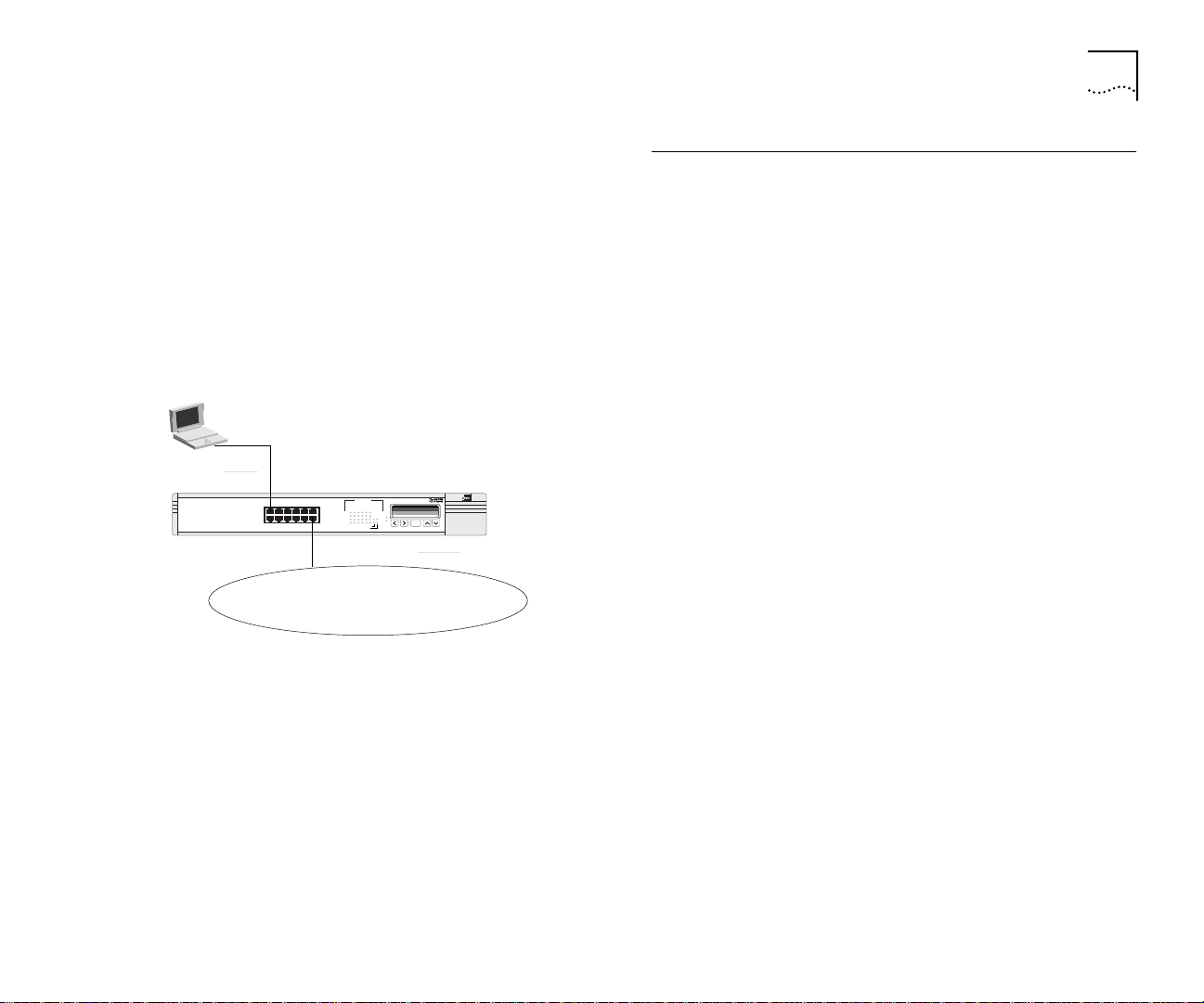
Ring Segmentation
High-speed switches offer a more efficient solution over 2-port PC bridges or routers. As illustrated below, segmentation
with a Token Ring switch brings immediate improvement over existing networks by re-distributing traffic
.
Ring Segmentation 1-5
16 Mbps
4 Mbps
SuperStack II Switch 2000 TRs
Connected with high-speed cascade
SuperStack II Hub TR
16 Mbps
16 Mbps
SuperStack II Hub TR
16 Mbps
SuperStack II Hub TR
Direct attach Workstations/Servers
16 Mbps
Server
Server
SuperStack II Hub TR
NETBuilder II
Figure 1-2 Using Switch 2000 TR to Segment Network
Page 16
1-6 CHAPTER 1: OVERVIEW
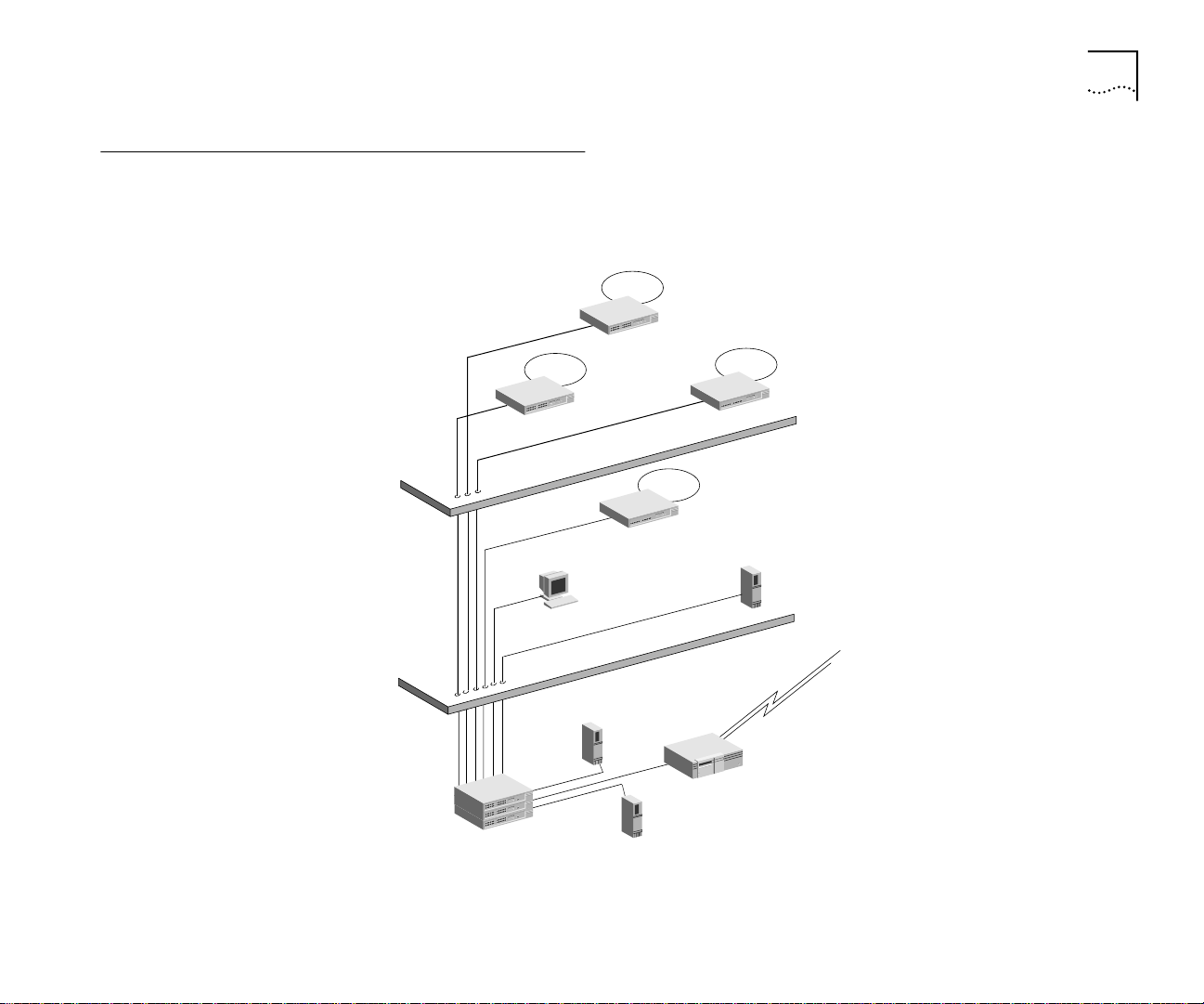
The Front Panel
This section describes the front panel components and LEDs of the SuperStack II Switch 2000 TR. Figure 1-3 shows the front
panel.
1
7
12 x RJ-45 ports
Figure 1-3 SuperStack II Switch 2000 TR Front Panel RJ-45 Ports
O
O C
C
LCD Status Display
Power
MGMT
LCD Control Buttons
Power LED
MGMT LED
SuperStack II
Switch 2000 TR
ENTER
Status and Activity LEDs
Link Status
green =link OK
yellow =MGMT partition
6
12
Packet—
Status —
Packet—
Status —
flashing yellow =auto error
off =inactive
5
4
1
3
2
5 6
4
123
7
11
8910
7
11
8910
Option Slot
Cascade
Option Slot
Status LEDs
Cascade
Status LEDs
6
12
12
Page 17

The Front Panel 1-7
RJ-45 Ports
12 RJ-45 ports support unshielded Twisted Pair (UTP)
or Shielded Twisted Pair cabling (STP) at 4 Mbps or 16
Mbps wire speed.
All 12 ports default to adapter mode for connection
to a Token Ring hub. Additionally, ports 1 through 4
can be configured to hub mode to allow direct
attachment of workstations or servers.
Front Panel LEDs
The LEDs on the front panel of the Switch 2000 TR
reflect the current status of the switch. Use Table 1-2
to interpret the LED states.
Table 1-1 LED States
LED Name Color Indicates
Packet LEDs Green Traffic present
Flashing yellow
Status LEDs Green Port inserted
Yellow Partitioned via management
Flashing yellow
Off Port not inserted
Option Slot
Status/Packet
Cascade
Status/
Packet
Green Presence of Option card
Flashing green Activity on link
Green Cascade connection present
Error frames present
Auto Error Partition
Table 1-1 LED States
LED Name Color Indicates
Flashing green Activity on link
Power Green Power ON
Yellow RPS w/alarm
MGMT Off Operation normal
Flashing green (slow) Software download
Flashing green (fast) Power On Self Test
(POST)
Yellow POST has failed
LCD Display Buttons
Use the LCD display on the front panel of the Switch
2000 TR to select ports, change system parameters,
receive status information, and set the Unit ID number.
■ Right and Left buttons—Change or move
digits or go to the previous menu.
■ Up and Down buttons—Scroll up or down in
specific menu and increase or decrease digit
value.
■ Enter button—Enter a menu or use to enter
the edit mode.
I
ENTER
Figure 1-4 LCD Display Buttons
Page 18
1-8 CHAPTER 1: OVERVIEW
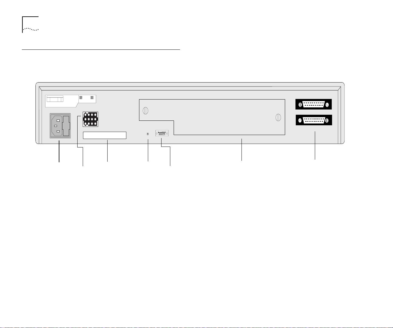
The Rear Panel
This section describes the rear panel components of the Switch 2000 TR. Figure 1-5 shows the rear panel.
Reset
IEC Power Socket
and Fuse Holder
Redundant Power
Serial Number
Figure 1-5 Switch 2000 TR Rear Panel
* Refer to the appropriate module installation manual for more information.
Reset Button
RS-232 Console
Optional Slide-In Module Slot*
High-Speed Cascade Connectors
Page 19

Optional Slide-In Modules 1-9
Power Socket
The Switch 2000 TR automatically adjusts to the
supply voltage. The fuse is suitable for both 110 AC
and 220-240 AC operation. Refer to “Replacing the
Fuse in Chapter 2 for information on replacing fuses.
NOTE: The Switch 2000 TR has no ON/OFF switch.
Serial Number
Refer to this number if you need to report a fault.
Redundant Power System Connector
Use this connector to attach a Redundant Power
System (RPS) to the Switch 2000 TR. Disconnect the
AC plug when using an RPS.
Reset Button
Using the Reset button simulates a power on/off
cycle. You can also perform a software reset using the
VT100 interface. Refer to “Setting Up the VT100
Console in Chapter 3.
Console Port
Use the RS-232 console port for connecting a terminal for serial remote or local out-of-band management and configuration. Use the following settings to
configure the VT100:
■ 9600 baud
■ 8 bit
■ No parity
■ 1 stop bit
Optional Slide-In Modules
Option modules provide alternate downlinks for the
Switch 2000 TR.
NOTE: Be sure the filler plate cover is installed when
the module slot is not occupied.
Slide-in modules are available for the following:
The ATM Module
The SuperStack II Switch TR ATM OC-3 module provides a high-speed ATM connection between the
Switch 2000 TR and ATM networks. When positioned
in workgroup or departmental LANs, the ATM downlink module offers a 155 Mbps data path to building,
campus or ATM network backbones directly from the
Switch 2000 TR. Perfect for providing cost-effective
ATM access to smaller isolated LANs or bandwidth
intensive and mission critical applications, the ATM
downlink also provides a logical migration path for
existing Token Ring LANs to mainstream high-speed
networking technologies.
Redundant links can protect your Switch 2000 TR
from network failure or equipment inconsistencies.
The built-in Software Upgrade feature allows you to
download software revisions easily.
Benefits of an ATM
ATM is the only computer networking technology
designed to carry video, voice and data traffic simultaneously. ATM provides the level of service necessary
Page 20

1-10 CHAPTER 1: OVERVIEW
to run each of these bandwidth-intensive applications
across networks.
The primary benefits of ATM include:
■ ATM is a cell-based communications technology
that easily scales from T1 or ATM 25 to OC-3 (155
Mbps), OC-12 (622 Mbps), OC-48 (2.488 Gbps),
and OC-192 (10 Gbps).
■ Additional services are easily added to existing
ATM networks.
■ ATM networks are designed for growth and pro-
vide future scalability.
■ ATM provides LAN Emulation (LANE) technology
which provides interoperability between existing
Token Ring, Ethernet, and ATM devices.
Summary of ATM Features
The following list summarizes the features of the
SuperStack II Switch 2000 TR ATM module.
■ Conforms to ATM Forum Standards
■ Meets OC-3c 155 Mbps interface
■ SONET (STS 3c) and SDH (STM-1) compliant
■ Multimode Fiber, SC connections
■ LAN Emulation (LANE) version 1.0
■ 16 Emulated LAN Clients
■ 512 Virtual Circuits
■ 1024 remote MAC addresses
■ User-to-Network Interface (UNI) 3.1
■ Interim Local Management Interface (ILMI)
■ AAL5 ATM Adaptation Layer
■ 16 Virtual LANs (VLANs)
■ Data buffer to store 40,000 ATM cells
■ Wire Rate Transmission on ATM port
■ Low Latency (68 microseconds between ATM and
Token Ring components).
■ 3Com SmartAgent support, including:
■ SNMP management using 3Com’s Transcend
Enterprise Manager.
■ Telnet management using VT100 interface.
The FDDI Module
The SuperStack II Switch TR FDDI module provides a
high-speed connection between the Switch 2000 TR
and FDDI backbone networks. When positioned in
workgroup or departmental LANs, the FDDI downlink
module offers a 100 MB data path to building,
campus or FDDI network backbones directly from the
Switch 2000 TR. Perfect for providing cost-effective
FDDI access to smaller isolated LANs or bandwidth
intensive and mission critical applications. The FDDI
downlink also provides a logical migration path for
existing Token Ring LANs to mainstream networking
technologies.
Redundant links can protect your Switch 2000 TR
from network failure or equipment inconsistencies.
The built-in Software Upgrade feature allows you to
download software revisions easily.
Page 21

Optional Slide-In Modules 1-11
Benefits of FDDI
Fiber Distributed Data Interface (FDDI) is a 100-Mbps
fiber optic local area network standard supported by
the ANSI committee.
The primary benefits of FDDI include:
■ A 100 Mbps point of aggregation for multiple
Token Ring segments.
■ Supports Single Attached Station (SAS) or Dual
Attached Station (DAS) functions.
■ Supports server connections via Token Ring FDDI
translation of IP, SNA, IPX, and NetBIOS.
■ Additional services are easily added to existing
FDDI networks.
■ FDDI networks are designed for growth and pro-
vide future scalability.
Summary of FDDI Module Features
The following list summarizes the features of the
SuperStack II Switch 2000 TR FDDI module.
■ Conforms to FDDI ANSI Standards
■ Wire Rate Transmission on FDDI port
■ Low Latency.
■ 3Com SmartAgent support, including:
■ SNMP management using 3Com’s Transcend
Enterprise Manager.
■ Telnet management using VT100 interface.
The Token Ring-in-Fast Ethernet (TR-in-FE) Module
TR-in-FE is a 3Com developed technology that encapsulates Token Ring frames in Fast Ethernet frames.
Bridging the gap between Token Ring and Ethernet,
this technology offers a more cost-effective integration than traditional bridging and routing, and allows
Token Ring users to expand their bandwidth while
preserving their TR infrastructure.
TR-in-FE is a unique way of combining Token Ring
and Ethernet for the purpose of utilizing Fast Ethernet
as a backbone and method of server attachment for
TR networks. Through a process known as tunneling
or encapsulation, TR-in-FE uses Fast Ethernet to
transport natively formatted Token Ring frames. This
means that both source route and transparent TR
frames addressing information is maintained through
Fast Ethernet (FE) so that it may be interpreted and
utilized by either a destination Token Ring (TR) switch
or FE server.
Benefits of TR-in-FE
TR-in-FE offers improvement in the following areas:
■ Scalability
■ TR switching
■ High-speed technologies
■ Wire-speed performance
■ Flexibility
■ High-speed flexibility (choice of D/L technology)
■ Desktop flexibility (TR, Ethernet)
Page 22

1-12 CHAPTER 1: OVERVIEW
■ Manageability
■ Simple to configure and administer
TR-in-FE allows both Token Ring and Ethernet to
share the same Fast Ethernet physical wiring infrastructure and server base without impacting network
performance. TR-in-FE accomplishes this by introducing routing or traditional bridging via Source-Route to
Transparent translation.
Fast Ethernet is relatively well understood and easy to
configure. Additionally, many tools exist to manage
and administer Fast Ethernet due to its wide acceptance in the industry and its similarity to Ethernet.
TR-in-FE benefits MIS managers most interested in:
■ Preserving existing investments in TR infrastructure
■ Seeking low-cost, high-speed connectivity
■ Combining Ethernet and Token Ring for common
server access
Fast Ethernet is less expensive than other options,
such as FDDI and ATM. Using FE, the price per port
for server attachment is 20% that of ATM and FDDI.
Summary of TR-in-FE Module Features
The following lists summarize the features of the
SuperStack II Switch 2000 TR TR-in-FE module.
■ Full duplex operation
■ Automatic configuration through PCI registration
■ RJ-45 connector for 100 Mbps data rates over cat-
egory 5 UTP wiring up to 100 meters
■ LEDs to indicate link integrity and link activity
■ Promiscuous mode support for NDIS 3.0 and
ODI32 drivers
■ Compliance with FCC Class B, CISPR B, and CE
■ Software configurable
■ DOS diagnostics and configuration utility
■ Support for frame sizes up to 3992 bytes
Token Ring switching allows the install base of TR
equipment and its configuration to remain intact and
operational while allowing for an upgrade to higher
performance through microsegmentation and interfaces to higher speed technologies. TR-in-FE represents one option for integrating Fast Ethernet into the
TR switched environment.
Page 23
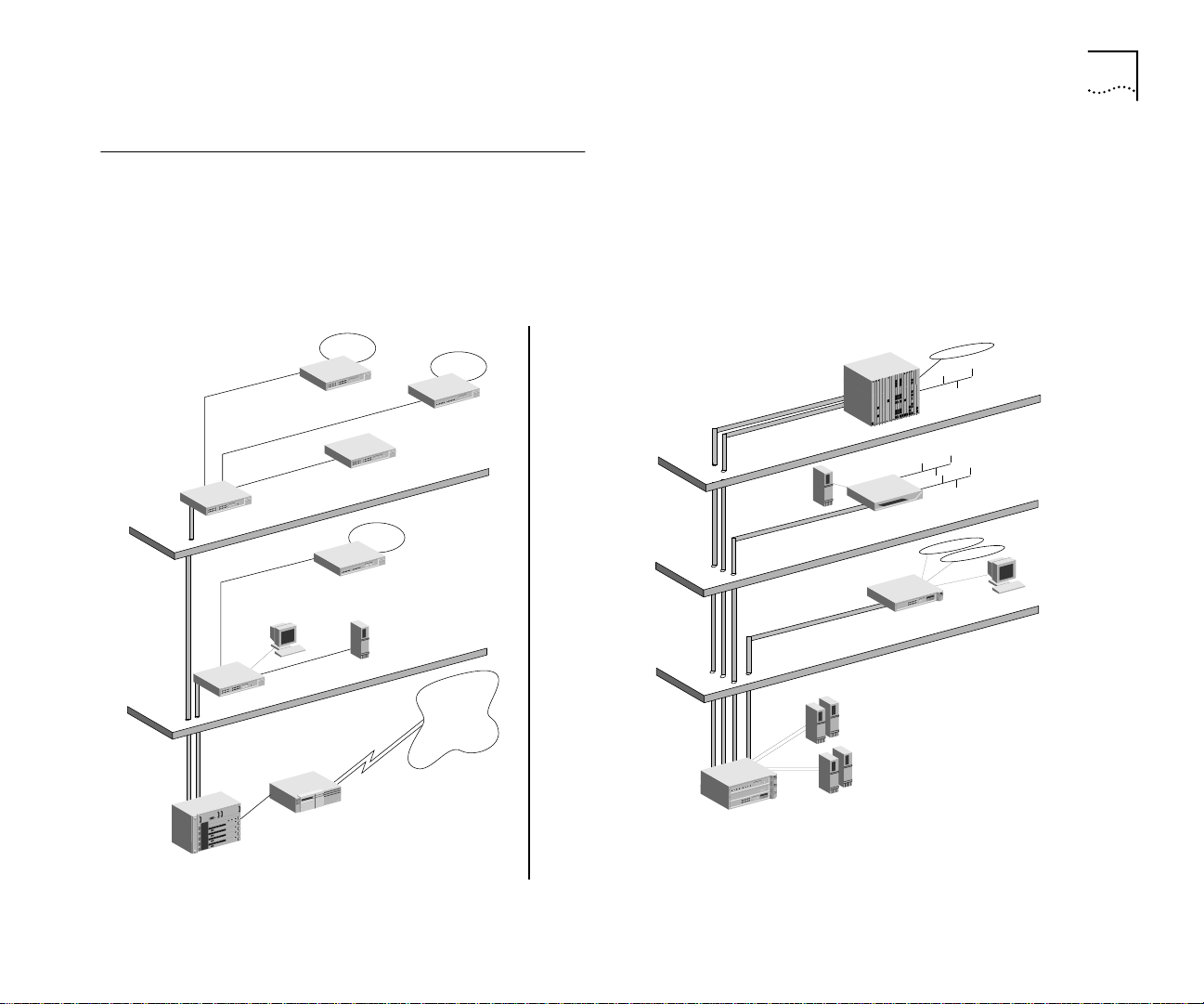
Migrating to High-speed Technologies
Managers want to migrate to FDDI, ATM, or TR-in-FE easily. Using Switch 2000 TRs, critical resources attach directly to
high-speed technologies while preserving the investment in Token Ring hardware. They also merge easily with existing network management applications. These features allow network managers to introduce additional switches, servers, and stations seamlessly via direct connections. Switch 2000 TRs can be contained in data centers while remaining connected to
high-speed links with single ATM, FDDI, or TR-in-FE module.
Migrating to High-speed Technologies 1-13
16 Mbps
SuperStack II Switch 2000 TR
ATM
SuperStack II Switch 2000 TR
CELLplex 7200
16 Mbps
4 Mbps
16 Mbps
16 Mbps
NETBuilder II
SuperStack II Hub TR
SuperStack II Hub TR
Direct attach
Workstations
SuperStack II Hub TR
SuperStack II Hub TR
WAN
SuperStack II Switch 3000 TX
SuperStack II Switch 2000 TR
SuperStack II Redundant Power System
Figure 1-6 Using Switch 2000 TR for Migration to High-Speed Technologies
CoreBuilder Chassis
Fast Ethernet
Server
SuperStack II Switch 1000 TX
SuperStack II Switch 2000 TR
Fast Ethernet
Servers
Token Ring
Servers
Direct attach Workstations
Page 24

1-14 CHAPTER 1: OVERVIEW
High-speed Cascade Connectors
These connectors provide a high-speed cascade connection between Switch 2000 TRs in a stack. You can
connect multiple units to form a single switched
domain. You can connect up to six Switch 2000 TRs
with these connectors.
A stack of Switch 2000 TRs act as a single multiport
switch. The setup configuration parameters are
shared among switches and the entire stack can be
managed and downloaded as a single IP entity.
Token Ring Switching Concepts
This section describes Token Ring Switching and
unique features of the Switch 2000 TR, including:
■ Why Token Ring Switching?
■ Source Route Bridging
■ Transparent Bridging
■ Source Route Transparent Bridging
■ Spanning Tree (802.1d and IBM)
■ Store-and-Forward
■ Cut-through
■ Dynamic Cut-through
■ Congestion Control
■ Workgroups
Why Token Ring Switching?
Existing Token Ring networks are built around shared
media technology and typically operate at 16 Mbps
wire speed. This 16 Mbps of bandwidth is shared
between all stations on the ring. As applications
become more sophisticated, or as work-stations
become more powerful, or as the number of users
per ring grows, the demand for bandwidth increases.
As a result, stations are limited not by their own processing power but by the limitations of the physical
network.
In an effort to reduce the traffic per ring and increase
the overall bandwidth availability, existing rings have
been divided into multiple smaller rings. This division
provides more bandwidth per station.
With an optional FDDI or ATM downlink module,
Token Ring switching also solves problems found in
client-server applications where a shared 100 Mbps
(FDDI) or 155 Mbps (ATM) pipeline can provide easy
access to servers and WAN links.
The major benefits of Token Ring switching are:
■ Bandwidth relief
■ Migration path to high-speed technologies
■ Cost-effective method for achieving LAN intercon-
nectivity
Source Route Bridging (SRT)
Source Route Bridging is a method of allowing a ring
station (node) on a Token Ring network to communicate with another ring station on a different ring
interconnected by bridges. The “source” ring station,
in other words, the node initiating the communication, is responsible for dynamically determining and
then maintaining information about the “route” to
Page 25

Token Ring Switching Concepts 1-15
the destination ring station. A route is simply the path
a packet takes through a source route bridged network from the source ring station to the destination
ring station.
In a multiple ring environments, nodes on different
rings need additional bridging information before
they can communicate with each other. A source ring
station must first determine if one or more routes
exist to another station on a remote ring.
In general, the source ring station determines the
route by sending a “discovery” packet out across the
multi-ring network. Source routing bridges forward
this “discovery” packet while adding path information. Likewise, switches forward any response from
the destination ring station to the “discovery” packet
originator. When a source ring station receives a
response it updates its own bridging table with the
information. After determining the optimal path, the
ring stations include the path information in every
packet transmitted between them.
Switching provides connectivity between LANs, forming enterprise-wide networks. In a Token Ring environment, source routing switches connect Token Ring
LANs and enable peer-to-peer and terminal-to-host
communications across both local and wide area
Token Ring networks. Both PC workgroup protocols
and IBM’s Systems Network Architecture (SNA) networks are supported by source routing switches.
Another advantage of switching is that it allows the
segmentation of the Token Ring network into multiple rings to reduce traffic on any one particular ring
segment. The adjacent rings may be connected by
parallel source routing switches to provide fault tolerance. In the event one switch fails, the other parallel
switch can be configured to automatically maintain
connectivity, providing an alternate route for data
between the two rings.
Transparent Bridging (TP)
Transparent bridging provides the simplest data communication method. In transparent bridging end stations are not aware of existing intermediate bridges.
As such, a transparent bridge learns about its surrounding network from the source addresses of the
packets that it receives. Forwarding decisions are
based on the destination addresses contained in the
MAC header. Transparent bridges consult their bridging table (see “Bridge Table) to determine which port
should forward the traffic on to the destination port.
Bridge Table
A switch dynamically manages and updates its bridging table. All switches receive every packet transmitted on the segments attached to its ports. As a result,
a switch is able to “learn” the source MAC addresses
of each station that transmits packets on its attached
segments. Since a switch never places its own MAC
address in a packet that it forwards, the received
source MAC address always identifies the original
transmitter of the packet.
A switch uses the received source address information
to construct its bridging table. The bridging table contains a list of all received MAC addresses and the
ports on which they were learned. From its bridging
Page 26

1-16 CHAPTER 1: OVERVIEW
table, a switch knows which port must be used to
reach each known MAC address.
Every time a switch receives a packet, it examines its
bridging table to determine if the source MAC
address is contained in its bridging table. If it is not, it
creates a new entry. The switch then searches its
bridging table for the address contained in the
packet’s destination address field. The switch then
forwards the packet to the port associated with the
destination MAC address. If the port specified in the
bridging table is the same port on which the packet
was received, the switch discards the packet.
The “learned” entries in the switch’s bridge table are
subject to aging. That means that if the switch does
not receive a packet from each entry before the
entry’s Age Timer expires, the switches bridging table
deletes the entry. This feature allows entries associated with dormant stations to be removed from the
switch’s bridge table.
Source Route Transparent Bridging
As the name implies, source route transparent (SRT)
bridge performs both source routing and transparent
bridging. If a frame with routing information is
received at the bridge, the bridge performs source
route bridging. Likewise, if a frame without routing
information is received at the switch, the switch performs transparent bridging.
Spanning Tree
Spanning Tree support is provided in the Switch 2000
TR.
■ 802.1d Spanning Tree
■ IBM Spanning Tree
802.1d Spanning Tree
Spanning Tree is an industry standard protocol
(802.1d) which prevents redundant paths (loops)
from existing within a network. By ensuring that only
one active data path exists between any two rings,
the Spanning Tree protocol prevents the following:
■ Packet duplications
■ Broadcast storms
■ Packet misordering
In addition, Spanning Tree also provides fault tolerance within the network by automatically reconfiguring the active topology if a fault is detected in the
network. This provides contingency paths in the event
that the active path is disabled and guarantees stability.
IBM Spanning Tree
IBM Spanning Tree operates the same as 802.1d in
that it resolves network loops. However, IBM Spanning Tree uses different addresses and parameters
which do not interoperate with 802.1d Spanning
Tree.
The IBM Spanning Tree algorithm reduces the number
of broadcast frames in source routed networks. A
single path is formed between networks from the
root bridge. IBM Spanning Tree applies only to Spanning Tree Explorer frames (STEs). All Route Explorer
frames (AREs), and Specifically Routed Frames (SRFs)
Page 27

Token Ring Switching Concepts 1-17
can use any path in the network. ARE packets are
flooded through all bridges onto all rings. This creates
multiple copies if redundant paths exist in the network.
When multiple requests are received at the destination; each one causes a response. Implementing
Spanning Tree ensures that the number of broadcast
packets are significantly reduced.
For more information on Spanning Tree, refer to
“Spanning Tree Fields in Chapter 4.
Congestion Control
Congestion control prevents loss of packets due to
congestion on destination ports. You have a choice
among:
■ Flow Control—Flow control balances the band-
width use of the client ring to that of the server
ring. This is especially useful in focused load conditions where many ports are sending data to a
single port.
Flow control monitors buffer usage and shifts the
load onto the end station. This allows the Switch
2000 TR to use the available bandwidth to access
the port by balancing traffic on the sending ports.
■ Nonblocking—Occasionally packets that are des-
tined for a particular port cannot be delivered. This
is especially true if a ring is busy or not operating.
These packets inadvertently impede the delivery of
packets destined for known good or free rings.
Nonblocking provides a means for discarding packets that can not be delivered while ensuring deliv-
ery of packets with known good or free
destinations.
■ Off—In Off mode there is no congestion control.
Packet transfers are based on queue availability in
the receive buffer. If there is no buffer space on the
receiving port, packets are dropped.
Forwarding Modes
Switch 2000 TR provides three forwarding methods.
■ Store-and-Forward—Switch 2000 TR can use a
conventional store-and-forward method typically
found in bridges. In this mode, packets are
received and buffered (stored) in their entirety
before they are forwarded. This guarantees that
errored frames on the source ring are not forwarded to the destination. Although
store-and-forward guarantees packet stability, it
also involves a transit delay depending on the
length of the packet.
■ Cut-thru—Cut-thru avoids the transit delay found
in standard store-and-forward methods. Although
cut-through can be applied only between ports
that are operating at the same wire speed or from
a high speed port to a low speed port, it does provide better transit rates by forwarding a frame as
soon as enough information is available to determine the destination port.
■ Dynamic Cut-thru—In Dynamic Cut-thru mode
the switch monitors error rates on the source. If a
user set threshold is exceeded, the switch port
changes to store and forward mode until the error
rate reduces. At this point the port reverts to
Page 28

1-18 CHAPTER 1: OVERVIEW
VLANs
Cut-thru mode. The default mode for the Switch
2000 TR is Dynamic Cut-thru.
A VLAN is defined as a group of location- and topology- independent devices that communicate as
though they were on the same physical LAN. This
means that they are not restricted by the hardware
that physically connects them, and segments are
defined by flexible user groups created by the user.
For example, with VLANS, the user can define a network according to:
Department Groups—A VLAN could be created for
the Marketing Department, another VLAN for the
Finance Department, and still another for the Development Department.
Hierarchical Groups—A VLAN could be created for
directors, another for managers, and still another for
general staff.
Usage Groups—A VLAN could be created for Email
users, another for multimedia users, and so on.
VLANs facilitate the administration of logical groups
of stations that can communicate as though they
were on the same LAN. VLANs also facilitate moves,
adds, and changes of members of logical groups.
Traffic between VLANs is firewalled. This limits the
propagation of multicast and broadcast traffic
between VLANs.
Each distinct VLAN is uniquely identified throughout
the bridged LAN. A consistent representation of a
VLAN exists across a VLAN fabric (including ATM).
This means that the shared VLAN knowledge of a particular packet remains the same as the packet travels
from one point to another.
Advantages of VLAN
All 802 media and shared media support VLANs. In
addition, implementing VLANs:
■ Eases the change of devices
■ Helps control broadcast traffic
■ Provides extra security
Page 29
2
GETTING STARTED
This chapter describes the installation and setup procedures for the Switch 2000 TR:
■ Important Safety Information
■ Positioning the Switch 2000 TR
■ Installing the Slide-in Modules
■ Installing the Switch 2000 TR
■ Connecting Redundant Power System
■ Connecting to the Serial Port
■ Device Defaults
Important Safety Information
NOTE: Warnings contain directions that you must
follow for your personal safety. Follow all instructions
carefully. Please read the following safety information
before installing the Switch 2000 TR.
■ Installation or removal of any add-in module or
cable must be performed by qualified personnel
only.
■ The Switch 2000 TR must be attached to a
grounded power source.
■ The power cord must comply with the standards of
the country in which the Switch 2000 TR is to be
installed.
■ For USA and Canada:
■ The cord must be UL-approved and CSA certi-
fied.
■ The minimum specifications for the flexible
cord:
No. 18 AWG
Type SV or SJ
3-conductor
■ The cord must have a rated current capacity of
at least 10 Amps.
Page 30

2-2 CHAPTER 2: GETTING STARTED
■ If the power supply plug is unsuitable and you
must replace it, refer to the following specifications:
■ Brown wire to the Live (Line) plug terminal. The
terminal may be marked with the letter L or colored red.
■ Blue wire to the Neutral plug terminal. The ter-
minal may be marked with the letter N or colored black.
■ Yellow/green wire to the Ground (earth) plug
terminal which may be marked with the letter
(E) or the earth symbol or colored yellow/green.
■ The Switch 2000 TR operates under SELV condi-
tions (Safety Extra Low Voltage) according to IEC
950. This standard is complied with only when the
unit is connected to equipment following the same
standard.
■ Use only fuses of the same type and manufacture
with the Switch 2000 TR.
CAUTION: Never remove the cover. The Switch 2000
TR contains no user-serviceable parts.
Positioning the Switch 2000 TR
The Switch 2000 TR is suited for data center and
workgroup applications. It can be mounted in a standard 19-inch rack, on a wall, or free-standing on a
table or similar surface. A mounting kit with two
brackets is provided for wall or rack mounting.
Considerations for Placement
Be aware of the following considerations when
installing the Switch 2000 TR:
■ Can cable lengths and media be supported prop-
erly?
■ Is cabling located away from sources of electrical
noise such as radios, transmitters and other radio
frequency equipment?
■ Are all objects removed from the top of the unit or
stack?
■ Is air flow adequate through the side vents?
■ Is unit installed in moisture and water-proof envi-
ronment?
CAUTION: Never remove an Optional Slide-in
module filler plate without disconnecting the power
source first.
Page 31

Installing the Slide-in Modules 2-3
Configuration Guidelines
The cable topology rules for Token Ring are shown
below:
Media 4 Mbps 16 Mbps
Category 3 UTP 660 ft/200m 330 ft/100m
Category 4, 5 UTP 1,320 ft/400m 660 ft/200m
Type 1 STP 2,000 ft/600m 1,000 ft/300m
Power Supply and Fuse
The Switch 2000 TR automatically adjusts to the supplied voltage. The fuse is suitable for either 90-110V
A.C. or 220-240V A.C. A spare fuse is provided in the
fuse drawer.
Replacing the Fuse
Refer to Figure 2-1 for the location of the fuse. When
necessary, replace the Switch 2000 TR fuse with a
fuse that has the following specifications:
■ 250 volts — 4A Slo-Blo
1 Power down the Switch 2000 TR by removing the AC
power cord or the Redundant Power System cords.
2 Gently pry open the fuse holder cover with a small
flat-blade screwdriver.
Fuse location
AC connector
Figure 2-1 Switch 2000 TR Fuse Location
3 Slide out the fuse holder drawer and remove the fuse.
4 Install the replacement fuse and close the fuse
drawer.
5 Re-insert the power cord and apply power.
Installing the Slide-in Modules
This section explains how to install the three optional
modules into a SuperStack II Switch 2000 TR device.
The modules are:
■ ATM
■ FDDI
■ TR-in-FE
Page 32

2-4 CHAPTER 2: GETTING STARTED
CAUTION: Always follow Electrostatic Discharge
(ESD) procedures when installing an I/O Module.
1 If the Switch is connected to the network, turn off the
power and disconnect the switch from the main
power supply and the network.
2 Place the Switch on a flat, clean, hard, work surface.
3 Locate and remove the blanking plate that covers the
slot. See Figure 2-2. Retain the blanking plate and the
screws for future use.
4 Use the guide rails within the Switch slot to align the
module. The location of the guide rails and the correct positioning of the plate is shown in Figure 2-2.
5 Slide the module into the slot without touching the
top or bottom of the circuit board, which positions
upside down on the plate. Ensure that the module is
pushed fully into the unit.
6 Use the thumb screws attached to the module to fix
the module firmly into place.
7 Connect the cable to the module port.
Token Ring-In-Fast Ethernet Module
Full Duplex
Port Status
Reset
Console Port
9600,8,1,N
Tx
Rx
Tx
Rx
3C510620
Board postions with
electronics facing down
Figure 2-2 Inserting a Slide-in Module into a Switch 2000 TR
NOTE: For cable specifications see the guide that
came with your module.
8 Each end of the cable has a transmit (Tx) and receive
(Rx) connector. Connect the Rx connector to the
port’s Tx socket. Connect the Tx connector to the
port’s Rx socket. Do the same at the other end of the
connection.
9 Power up the switch. The link status LED turns green
once a valid connection is made.
Page 33

Installing the Switch 2000 TR 2-5
Installing the Switch 2000 TR
Rack Mounting
The Switch 2000 TR fits a standard 19-inch data communications rack typically found in wiring closets.
1 Unpack the Switch 2000 TR and place it on a hard,
flat surface.
2 Position one of the enclosed mounting brackets over
the mounting holes and attach. See Figure 2-3.
Figure 2-3 Rack Mounting the Switch 2000 TR
for mounting the unit. A flat, smooth surface that is
dry and sturdy is best.
1 Unpack the Switch 2000 TR and place on a hard, flat
surface.
2 Position one of the enclosed mounting brackets over
the mounting holes and attach. See Figure 2-4.
Figure 2-4 Wall Mounting the Switch 2000 TR
3 Repeat the process for the second bracket.
4 Mount the Switch 2000 TR to the wall. Be sure to
allow for adequate ventilation.
3 Repeat the process for the second bracket.
4 Insert the Switch 2000 TR in the rack and secure it
with suitable screws (not included). Be sure to allow
for adequate ventilation.
Wall Mounting
The Switch 2000 TR can be mounted to a wall with
the enclosed brackets. Be sure that the wall is suitable
Stack Mounting
The Switch 2000 TR can be stacked with other components of the SuperStack system using the four
enclosed self-adhesive rubber pads. Apply the rubber
adhesive pads to the underside of the unit. Stack the
units, ensuring that the pads of the upper unit sit in
the recesses in the cover of the lower unit.
Page 34

2-6 CHAPTER 2: GETTING STARTED
Connecting Redundant Power System
To install an RPS, proceed as follows:
1 Power down by disconnecting the AC power cord on
the Switch 2000 TR.
2 Connect an RPS cable assembly to the RPS connector
on the back panel of the Switch 2000 TR.
3 Connect the other end of the RPS cable assembly to
the RPS connector on the back panel of the RPS unit.
Connecting to the Serial Port
The Switch 2000 TR serial port settings are set to:
■ Character size—8
■ Parity—None
■ Stop Bit—1
■ Baud Rate—9600
Terminals connected to the Switch 2000 TR must be
configured to these same settings before you can
communicate.
Connecting a VT100 Terminal
To connect a VT100 terminal directly to the serial port
on the Switch 2000 TR you need a standard null
modem cable. Follow these steps:
1 Connect one end of the cable to the serial port on the
Switch 2000 TR and the other end to the serial port
on the VT100 terminal.
2 Ensure that your terminal is configured to the appro-
priate settings listed above.
Device Defaults
The tables list the factory defaults for the Switch 2000
TR.
Table 2-1 Unit Defaults
Unit ID #6
CAUTION: Setting the Unit # ensures that all configu-
ration parameters are retained when connecting
additional switches. Change this number to reflect
position of switch in stack. The first (bottom) switch
should be set to 1.
Connection to the serial port can be direct for local
management or through a modem for remote management.
For more information on the serial port console, refer
to “Setting Up the VT100 Console in Chapter 3.
Table 2-2 Port Defaults
Admin State Enabled
Workgroup ID Unit 1
Personality Ports 1 through 12 adapter
Internal Priority Normal
Congestion Control Non-blocking
Token Priority Normal
Page 35

Device Defaults 2-7
Speed 16 Mbps
Forwarding Mode Cut-through
Dynamic Cut-thru
Rising
Falling 10%
Broadcast Storm
Rising Threshold
Falling Threshold 50%
Rising Action none
Falling Action none
Port Bridge Defaults
Priority 100
Path Cost 62
Attached LAN ID FFFF (hex)
Max-Route Desc. 8
STE Mode Auto-Span
Table 2-3 Stack Defaults
BootP Client Enable
20%
60%
Spanning Tree Support Disabled
Spanning Tree Parameters:
Priority 32768
Max Age 20 seconds
Hello Time 200 seconds
Forward Delay 15 seconds
Transparent Parameter:
Entry Age 300 seconds
802.1d
Table 2-4 Workgroup Defaults
WorkGroup Name WGroup Created (single)
Table 2-5
Number of Ports 12
Bridge Type SRT
BPDU Address C0-00-00-00-01-00
Bridge Defaults
Page 36

2-8 CHAPTER 2: GETTING STARTED
Page 37

3
SETTING UP FOR MANAGEMENT
This chapter describes background information for
configuration and the procedures for initial setup of
the SuperStack II Switch 2000 TR, including:
■ Switch 2000 TR Management Options
■ Configuring Switch 2000 TR in Stack
■ Managing over the Network
■ Management Prerequisites
■ Switch 2000 TR Management Consoles
■ Setting Up the VT100 Console
■ Setting Up the LCD Console
■ Setting Up BOOTP
■ Auto Logout
■ Upgrading Software
■ Resetting the Switch 2000 TR
The first step required for setup is assigning a Unit ID
number which you configure with the LCD Console.
Refer to “Management Prerequisites, Setting Unit ID”
for instructions on assigning the Unit ID. You have
two methods for the initial setup—VT100 or LCD
console. When the switch has been configured for
management, you assign the remainder of the
parameters as described in Chapters 4 and 5.
Switch 2000 TR Management Options
You manage the Switch 2000 TR using one of the following communication methods:
■ Use an SNMP network manager such as Tran-
scend® Enterprise Manager over a network running IP protocols. Each network manager
application provides its own user interface.
■ Use the VT100 interface for out-of-band commu-
nications by connecting a VT100 terminal (or
workstation with terminal emulation software) to
the serial port of the Switch 2000 TR.
■ Use the VT100 interface over a TCP/IP network for
in-band communications using a workstation running a VT100 terminal emulation program and Telnet.
■ Use the front panel liquid crystal display (LCD) and
associated buttons.
These communications methods are summarized in
the following table and explained in detail in following sections.
Page 38

3-2 CHAPTER 3: SETTING UP FOR MANAGEMENT
Table 3-1 Switch 2000 TR Management Options
Access mechanism Allows you to. . . Using . . .
Serial Port Establish an
out-of-band connection to the VT100 console.
IP Establish in-band
connection to the
VT100 console
SNMP Manage devices using
SNMP network management application
LCD Set basic parameter,
view port status, and
set Unit ID
VT100 Console
Telnet on TCP/IP
protocol stack
SNMP on TCP/IP
protocol stack
Front panel
display
VT100 Management Interface
The menu-driven interface for the Switch 2000 TR is
known as the VT100 interface or Local Management
interface. Using a simple series of menus, the VT100
interface provides access to switch functions, including port, stack, unit, bridge, switch, and workgroup
settings and statistics; communication parameters,
and security levels for individual users. Refer to “The
VT100 Console” for more information.
You establish VT100 management communications
with the Switch 2000 TR via the serial port or an IP
Network connection as explained next.
Via the Serial Port
Access the management interface via a VT100 terminal or using VT100 terminal emulation software. You
can connect directly to the Switch 2000 TR using the
serial port or via a modem connection. This method is
especially useful for initial setup and configuration or
if the device is not reachable via network management applications.
This method allows you to manage the Switch 2000
TR when:
■ You configure and initialize the system.
■ The LAN is unable to provide reliable service.
■ The network manager does not have direct LAN
connection.
■ The network manager software does not support
SNMP.
When a connection has been established, the main
Switch 2000 TR banner appears and you can log on.
Via an IP Network Connection
Access the management interface via a Telnet utility
over a network running TCP/IP. The console interface
is the same as that of the interface for the serial port.
The Telnet application requires a VT100 terminal emulation application interface.
Before you can start a Telnet session, you must set up
the IP parameters. To open a Telnet session, you must
specify the IP address of the device you want to manage. Up to three Telnet sessions can exist simultaneously.
When a connection has been established, the main
Switch 2000 TR banner appears and you can log on.
Page 39

Configuring Switch 2000 TR in Stack 3-3
Configuring Switch 2000 TR in Stack
Head Unit
One of the unique characteristics of the Switch 2000
TR is its ability to be part of a stack. When installed as
members of a stack, up to 6 Switch 2000 TRs form
the equivalent of a switching chassis, managed using
the same IP address. All traffic, management, monitoring, and configuration tasks and inquiries operate
through the high-speed cascade interface located at
the rear of each unit. See Figure 3-1.
Configuration rules for the Switch 2000 TR are simple:
■ The head unit must have the lowest Unit ID
number in the stack.
■ The head unit should be at the bottom of the
stack.
■ It is recommended that each consecutive unit have
sequential Unit IDs.
■ To ensure redundancy each consecutive unit
should have the same IP address setting as the
head unit.
SuperStack II
LINK STATUS
green =link OK
yellow =MGMT partition
1x
7x
1x
7x
1x
7x
1x
7x
1x
7x
1x
7x
flashing yellow =auto error partition
6x
off =inactive
1
Packet —
123
Status —
Packet —
7
12x
Status —
7
green =link OK
yellow =MGMT partition
flashing yellow =auto error partition
6x
off =inactive
1
Packet —
123
Status —
Packet —
7
12x
Status —
7
green =link OK
yellow =MGMT partition
flashing yellow =auto error partition
6x
off =inactive
1
Packet —
123
Status —
Packet —
7
12x
Status —
7
green =link OK
yellow =MGMT partition
flashing yellow =auto error partition
6x
off =inactive
1
Packet —
123
Status —
Packet —
7
12x
Status —
7
green =link OK
yellow =MGMT partition
flashing yellow =auto error partition
6x
off =inactive
1
Packet —
123
Status —
Packet —
7
12x
Status —
7
green =link OK
yellow =MGMT partition
flashing yellow =auto error partition
6x
off =inactive
1
Packet —
123
Status —
Packet —
7
12x
Status —
7
Switch 2000 TR
6
5
4
3
2
Power
5 6
4
C
12
O
11
8910
12
11
O C
8910
MGMT
ENTER
Option Slot
Cascade
SuperStack II
LINK STATUS
Switch 2000 TR
6
5
4
3
2
Power
5 6
4
C
12
O
11
8910
12
11
O C
8910
MGMT
ENTER
Option Slot
Cascade
SuperStack II
LINK STATUS
Switch 2000 TR
6
5
4
3
2
Power
5 6
4
C
12
O
11
8910
12
11
O C
8910
MGMT
ENTER
Option Slot
Cascade
SuperStack II
LINK STATUS
Switch 2000 TR
6
5
4
3
2
Power
5 6
4
C
12
O
11
8910
12
11
O C
8910
MGMT
ENTER
Option Slot
Cascade
SuperStack II
LINK STATUS
Switch 2000 TR
6
5
4
3
2
Power
5 6
4
C
12
O
11
8910
12
11
O C
8910
MGMT
ENTER
Option Slot
Cascade
SuperStack II
LINK STATUS
Switch 2000 TR
6
5
4
3
2
Power
5 6
4
C
12
O
11
8910
12
11
O C
8910
MGMT
ENTER
1
Option Slot
Cascade
Figure 3-1 Switch 2000 TR in stack setting.
Cascade Connections
Cascade connectors must attach from the top connector of bottom unit to the bottom connector of
next highest unit, up through the stack. See
Figure 3-2.
Unit ID #
6
5
4
3
2
Head Unit
Figure 3-2 Switch 2000 TR Cascade Connections
Page 40

3-4 CHAPTER 3: SETTING UP FOR MANAGEMENT
Managing over the Network
Any network manager application running Simple
Network Management Protocol (SNMP) can manage
the Switch 2000 TR, provided the Management Information Base (MIB) is installed correctly on the management station. SNMP files for all 3Com products
are available on the “3Com Bulletin Board Service” in
Appendix F.
Network management applications provide their own
user interface to the management facilities. 3Com’s
Transcend® family of network managers, for instance,
have all the facilities for managing the Switch 2000
TR. The Switch 2000 TR supports SNMP over TCP/IP
protocol.
IP Addresses
Internet Protocol (IP) addresses are designed using
dotted decimal notation, such as n.n.n.n, where n is a
number between 0 and 255.
A sample IP address is 192.128.40.120.
IP addresses have two parts:
■ The first part of the address (192.128.40 in the
example) identifies the network on which the
device resides. Network addresses are assigned by
international organizations. Each set of network
numbers is unique within the context of the Internet.
■ The second part of the address (.120 in the exam-
ple) identifies the device within the network.
Assigning unique device addresses is the responsibility of your network organization.
Operating IP in a Closed Network
If you are the manager of a network that has no connection to the outside world, you might not need
uniquely assigned network addresses. If you are using
the IP protocol for internal management of your network, you can assign arbitrary addresses, provided
each device is unique.
If you decide to use the IP protocol internally we suggest using addresses in the 192.100.X.Y, series where
X and Y are numbers between 1 and 254.
If you later connect to the outside world, you will
have to re-assign new, valid network numbers
assigned to your network by the NIC or other international organization. Refer to “Obtaining Network
Addresses”.
A subnet address is a filtering system for IP addresses.
We suggest using a general mask such as
255.255.255.0 if you are unsure what mask to use.
Obtaining Network Addresses
Contact one of the following organizations to obtain
a valid set of network addresses.
■ In the United States
InterNIC Registration Services
505 Huntmar Park Drive
Herndon, VA 22070
Telephone number:
Page 41

Management Prerequisites 3-5
1-800-444-4345, 1-619-455-4600, 1-703-742-4777
■ In Europe
RIPE NCC
Kruislaan 409
NL-1098 SJ
Amsterdam
The Netherlands
Telephone number:
+31 20 592 5065
■ In Asia Pacific
Asia Pacific Network Information Center (APNIC-DOM)
c/o Computer Center, University of Tokyo
2-11-16 Yayoi
Bunkyo-ku, Tokyo 113
Japan
Telephone number:
+81 3 3580 3782
Management Prerequisites
Before you can successfully operate and manage
the Switch 2000 TR you must assign a Unit ID
number to the device. This section describes the
necessary steps for assigning a Unit ID#.
The only method for assigning a Unit number is via
the LCD Console located on the front panel of the
Switch 2000 TR.
Locate the LCD Console and proceed as follows:
1 Power on the Switch 2000 TR.
Switch 2000 TR>Unit ID 6 appears in the LCD Console.
This is the factory default.
2 Press [Enter] to enter the working menu of the LCD
Console.
Switch 2000 TR>Unit appears.
3 Press [Enter].
UNIT>Unit # appears.
4 Press [Enter].
Unit #>6 appears.
5 Press the [Down Arrow] once. The number 1 appears.
6 Press [Enter]. The Unit ID number has now been set.
7 Press [Left Arrow] twice to return to the main LCD
Console menu.
Continue with the management setup as described in
the remainder of this chapter.
Page 42

3-6 CHAPTER 3: SETTING UP FOR MANAGEMENT
Source Routing Prerequisites
If you plan to operate the Switch 2000 TR in a source
routing environment, you need to assign a segment
ID. Follow the instructions below, from the Port Setup
screen:
1 Select Bridge from the bottom of the Port Setup
screen.
The Port Bridge Setup screen appears.
Figure 3-3 Port Bridge Setup Screen (Attached LAN ID Setting)
2 Assign an Attached LAN ID under the Source Routing
heading on the right side of the screen.
The Attached LAN ID is set to FFFF which is the
default setting for “not assigned.”
You must assign a value to this field to perform
source routing. Refer to “Setting Source Route Bridging in Chapter 4 for more information.
Switch 2000 TR Management Consoles
The following sections describe how to get started
managing your Switch 2000 TR. If you plan to
manage the Switch 2000 TR using IP or SNMP, you
will have to assign an IP address to the Switch 2000
TR using one of these interfaces:
■ VT100 Console Interface. See Chapter 4.
■ LCD Console Interface. See Chapter 5.
■ BootP may also be used to assign IP address. Refer
to “Setting Up BOOTP”.
The VT100 Console
This section describes the screen conventions used in
the Switch 2000 TR VT100 console interface. The
VT100 interface allows you to set and/or view these
switch parameters:
■ IP and associated addresses and management
■ Port personality, speed, and state
■ Bridge type, bridge number and Spanning Tree
state
■ Switch 2000 TR status and hardware and software
version numbers
Choice Field
Example display:
*text*
Text enclosed with asterisks is a list from which you
can select one option. Press [Space] to cycle through
the options. When your choice is highlighted press
Page 43

Switch 2000 TR Management Consoles 3-7
[Down Arrow] or [Return] to move to the next field.
Refer to “Switch 2000 TR VT100 Console Interface
Menu Map”.
Entry Field
Example display:
[text]
Text enclosed in square brackets on the screen indicates a text entry field. This field may be text, numeric
data, or hexadecimal data.
Password fields are hidden, meaning the text you type
is not shown on the screen.
In some cases an Entry field has a default entry. To
change the default value, simply type in a new value
for this field and the default entry will be erased.
Press [Down Arrow] or [Return] to move on to the
next field.
Button
Example display:
OK
Text for button is always shown in uppercase letters.
Buttons carry out actions. For example OK: or CANCEL. To select a button, move the cursor to the
button and press [Return].
List Boxes
Example display:
monitor, manager, or security
A list box allows you to select one or more items from
a list. These keys allow you to select from a list:
■ [Return]—moves the cursor to the next field. Car-
ries out a button’s action.
■ [Space Bar]—moves through a text list for a field.
Use it to highlight the item or value you want.
■ [Down Arrow]—moves down a list item by item
and starts over again at the top.
■ [Ctrl] + [U]—moves the cursor one screen up the
list box.
■ [Ctrl] + [D]—moves the cursor one page down the
list box.
Key Board Shortcuts
Here are some shortcuts you can use to navigate
within the console screens:
■ [Tab]—Moves from one field on a form to the next
on any screen without making a change.
■ [Return]—Moves you to the next form field after
you have made an entry.
■ [Left Arrow]—Moves you to the previous field on
the screen or the previous character in an editable
field.
■ [Right Arrow]—Moves you to the next field on
the screen or the next character in an editable
field.
■ [Ctrl] + [R]—Refreshes the screen.
■ [Ctrl] + [B]—Moves the cursor to the next button.
■ [Ctrl] + [P]—Returns to the previous screen.
Page 44

3-8 CHAPTER 3: SETTING UP FOR MANAGEMENT
■ [Ctrl] + [N]—Moves to the next screen after imple-
menting current screen settings.
■ [Ctrl] + [K]—Displays list of key strokes.
Correcting Text Entries
Use [Delete] on a VT100 terminal or [Backspace] on a
PC. This key moves the cursor one space to the left
and deletes a character. To delete more than one
character, press the key once for each character.
NOTE: Check carefully before using the Control keys.
If you are using Telnet or a terminal emulation program you may find that some Control keys do not
work the same or that they control other functions.
Refer to the documentation that accompanies your
Telnet or terminal emulation software.
Default Users
Three default user types are allowed by the resident
management console. They cannot be deleted or
altered by the network administrator. Refer to
Table 3-2 for default names and passwords. Refer to
Appendix B for a listing of Screen Access Rights.
Table 3-2 Default User Names and Passwords
Default Name Password Access Level
monitor monitor monitor
manager manager manager
security security security
Page 45

VT100 Console Menu Map
Figure 3-4 displays the menu structure for the Switch 2000 TR VT100 console interface.
VT100 Console Menu Map 3-9
Switch 2000
Main Banner
Switch
Management
Stack
Unit
Port
VLAN
Bridge
I/O Module
Switch 2000
Logon
Quick
Config
Bridge
Config
TR Port
Config
Switch 2000
Main Menu
User
Access
Levels
Local
Security
Create
User
Delete
Users
Change
User
Status
Fault
Log
Management
Setup
Setup
Traps
Serial
Port
Software
Upgrade
Initialize Reset
Remote
Poll
Poll
Logoff
Figure 3-4 Switch 2000 TR VT100 Console Interface Menu Map
Page 46

3-10 CHAPTER 3: SETTING UP FOR MANAGEMENT
Setting Up the VT100 Console
This section provides instructions for setting up the
VT100 console for local or remote management.
1 Connect a VT100-compatible terminal to the serial
port of the Switch 2000 TR. Configure the terminal to
the following settings:
■ 9600 baud
■ 8 data bits
■ 1 stop bit
■ No parity
2 Press [Return] one or more times until the Switch
2000 Main Banner appears. See Figure 3-5.
4 Log on using the default name security and pass-
word security. See Figure 3-6.
Figure 3-6 Logon Screen
5 Select OK. The Main Menu appears. See Figure 3-7.
Figure 3-5 Main Banner
NOTE: You cannot modify these settings. If your ter-
minal is already set up with these values, the Main
Banner appears as soon as power-up completes.
3 Press [Return] at the Main Banner.
Figure 3-7 Main Menu
6 Select the Management Setup option.
The 3Com Switch 2000 TR Management Setup screen
appears. See “Switch 2000 TR Management Setup Fields”.
Page 47

Figure 3-8 Switch 2000 TR Management Setup Screen
7 Fill in the following fields:
■ Device IP Address
■ Device Subnet Mask (if applicable)
■ Default Router (if applicable)
8 Select OK when you have finished Management
Setup. You will be asked to confirm your settings.
9 Press [Enter]. Settings are confirmed.
10 Reboot the Switch 2000 TR by returning to the main
menu and selecting RESET. See “Resetting the Switch
2000 TR” on page 3-18.
You are now ready to communicate with the Switch
2000 TR using IP and an SNMP-based management
application.
Setting Up the VT100 Console 3-11
Switch 2000 TR Management Setup Fields
MAC Address
Displays the Switch 2000 TR unit MAC address.
Locally Admin Address
Use this field to assign locally administered addresses
to the management port. You need to reset the
Switch 2000 TR for the address to take effect. The
Locally Administered Address field allows you to
assign a unique MAC address to the unit. This feature
is useful for identifying specific units by their
addresses.
To set a Locally Administered Address, take these
steps.
1 Enter address in hexadecimal from the Locally Admin.
field. This must be in the range of 400000 000000 to
7FFFFF FFFFFF.
2 Select OK.
3 Reset the Switch 2000 TR.
NOTE: The Locally Administered address will not be
valid unless the Switch 2000 TR is reset. Refer to
“Resetting the Switch 2000 TR” for instructions on
resetting.
To reverse the Locally Administered address and revert
to the resident MAC address you must enter all zeros
and reset the Switch 2000 TR.
Page 48

3-12 CHAPTER 3: SETTING UP FOR MANAGEMENT
Work Group ID
The workgroup number for purposes of management. Management is only part of a single workgroup and should be viewed as a sub-net. If you
move your management setup to a new or different
subnet, you will need to change the workgroup ID.
Device IP Address
You must assign a unique address to the device in this
field. You change the IP address using this field.
Device SubNet Mask
You must assign a suitable network mask to the
device in this field. For a class B address, 255.255.0.0
is suitable. You change the Device SubNet Mask using
this field.
Default Router
Enter the IP address of the router with which the
Switch 2000 TR communicates. You can change the
Default Router IP address using this field.
NOTE: The above IP address parameters and Work
Group ID will not be valid unless the Switch 2000 TR
is reset.
SETUP TRAPS
Select this button to display the setup screen for
SNMP trap parameters. Refer to Chapter 4.
SERIAL PORT
Select this button to display the setup screen for serial
port parameters. Refer to Chapter 4.
Page 49

The LCD Console 3-13
ENTER
The LCD Console
This section describes the LCD Console. The LCD
Console allows you to enter specific configuration
parameters and obtain status data on the Switch
2000 TR without using a management workstation
console or application.
Switch 2000 TR
Switch 2000 TR
Unit Id. 1
Unit Id: 1
ENTER
Figure 3-9 Switch 2000 TR LCD Console
Use the left, right, up, down, and enter buttons to
view, enter, edit, or delete configuration parameters.
■ Unit ID
■ IP and associated addresses and management
■ Port personality, speed, state
■ Bridge type and Spanning Tree state
■ Switch status; hardware and software versions
Left Arrow
Use the left arrow to go to the previous menu.
Right Arrow
Use the right arrow to move to a specific digit on any
data field line.
Up Arrow
Use the up arrow to scroll up in a specific menu or to
decrease the value of a highlighted digit.
Down Arrow
Use the down arrow to scroll down in a specific menu
or to increase the value of a highlighted digit.
LCD Console Buttons
Enter
Use this button to accept or change data on any field
or scroll further down in LCD menu.
Page 50

3-14 CHAPTER 3: SETTING UP FOR MANAGEMENT
LCD Console Menu Map
Figure 3-10 displays the menu structure for the LCD console interface on the front panel of the Switch 2000 TR.
Switch 2000 TR
Switch 2000 TR
Unit Id. 1
Unit Id. 1
Legend:
ENTER accepts
selection and moves
to next menu
LEFT ARROW returns
to previous menu
RIGHT ARROW moves
to next digit
UP/DOWN ARROWS
scroll through a
specific menu
ENTER
ENTER
Switch 2000 TR
> Unit
Switch 2000 TR
> Port
Switch 2000 TR
> I/O Module
Switch 2000 TR
> Bridge
Switch 2000 TR
> Management
ENTER
ENTER
ENTER
ENTER
ENTER
Unit #
Port ID
Personality
Speed
Port State
Link State
Module Type
Module State
HW Version
SW Version
Boot SW Version
Bridge Type
Spanning Tree
I
P Mgmt
I
P Mgmt
ENTER
ENTER
ENTER
ENTER
ENTER
ENTER
Port ID
Personality
Speed
Port State
Link State
SRT
Transparent
Source-Route
802.1d
IBM
Disabled
IP Address
Subnet Mask
Default Router
ENTER
ENTER
Port ID
Personality
Speed
Port State
Link State
ENTER
ENTER
IP Address
Subnet Mask
Default Router
Switch 2000 TR
> Status
Switch 2000 TR
> Reset
Figure 3-10 Switch 2000 TR LCD Console Menu Map
ENTER
ENTER
HW Version
SW Version
Boot SW Ver
Confirm RESET?
Confirm RESET?
Y<ENTER> : N <-
ENTER
ENTER
Switch 2000 TR
RESETTING . . . .
Page 51

Setting Up the LCD Console 3-15
Setting Up the LCD Console
This section provides instructions for setting up the
LCD console for local or remote management.
1 Press the [Enter] button on the front panel LCD to
enter the main menu.
Switch 2000 TR
Switch 2000 TR
Unit Id. 1
Unit Id: 1
ENTER
Figure 3-11 Front Panel LCD Main Banner
2 Press [Down Arrow] until the Switch 2000 TR >Man-
agement screen appears.
3 Press [Enter] to enter the management menu and
select the desired management type.
At this point you can choose IP.
■ If you choose IP, you need to assign an IP address,
subnet mask and default router in order to communicate with the Switch 2000 TR. Refer to “IP
Address Setup” on.
IP Address Setup
From the Management>IP Mgmt screen, proceed
as follows:
1 Press [Enter] to select IP address field.
The IP Mgmt >IP Address screen appears.
2 Press [Enter].
A blank decimal notation appears on the IP Address.
3 Enter IP address as follows:
■ Select the value of the digit by moving the
[Up or Down Arrow] until the desired value
appears. Choose from 0 through 9 and “.”.
■ Select the next digit by moving the [Right
Arrow].
NOTE: Be sure to use standard dotted decimal nota-
tion for the IP address.
4 Press [Enter] to accept the address.
If the address is valid, you return to the previous
menu by pressing [Enter]. If the address is invalid an
error message displays and returns you to the previous menu when you press [Enter].
5 Press [Down Arrow].
The IP Mgmt >Subnet Mask screen appears.
6 Press [Enter].
A blank decimal notation appears in the Subnet Mask
field.
7 Enter the Subnet Mask address as follows:
■ Select the value of the digit by moving the
[Up or Down Arrow] until the desired value
appears. Choose from 0 through 9 and “.”.
■ Select the first digit by moving the [Right Arrow].
8 Press [Enter] to accept the address.
9 Press [Down Arrow].
The IP Mgmt >Default Router screen appears.
Page 52

3-16 CHAPTER 3: SETTING UP FOR MANAGEMENT
10 Press [Enter].
A blank decimal notation appears in the Default
Router field.
11 Enter the Default Router address as follows:
■ Select the value of the digit by moving the
[Up or Down Arrow] until the desired value
appears. Choose from 0 through 9 and “.”.
■ Select the desired digit by moving the [Right
Arrow].
12 Press [Enter] to accept the address.
13 Press [Left Arrow] to return to the higher level screens
in the LCD console.
NOTE: RESET the Switch 2000 TR for any address set-
tings to take effect. Refer to “Resetting the Switch
2000 TR” for instructions.
You are now ready to communicate with the Switch
2000 TR using IP and an SNMP-based management
application. Refer to Chapter 5 for more information
on configuring the bridge, port, and other management tasks.
Setting Up BOOTP
The BOOTP option allows you to enable or disable the
bootstrap protocol. The BOOTP (bootstrap protocol)
allows the switch to discover and learn its own IP
address and routing table information. To configure a
Switch 2000 TR with the BOOTP option you will need
a BOOTP server program. The MAC address, recorded
on a label on the rear panel of the Switch 2000 TR,
must be entered in the BOOTP server program along
with the corresponding IP address of the Switch 2000
TR and its default route information. This allows the
BOOTP request from the agent to be logged by the
BOOTP server which then supplies the required IP
information.
Table 3-3
BOOTP State IP Address Configured BOOTP Requests. . .
Enabled
(default)
Enabled Yes Not sent, IP address is
Disabled Yes/No Not sent
No Sent continuously (approx.
every 512 secs.) until
address is discovered
known
Follow the instructions below to set the BootP communications parameters.
1 Log on to the Switch 2000 TR.
2 Select Switch Management from the main menu.
3 Select *Stack*
4 Select Setup.
The Stack Setup screen appears. See Figure 3-12.
Page 53

Figure 3-12 Stack Setup Screen (BootP Setup)
5 (Optional) Enter a sysname for the stack.
6 Toggle the [Space Bar] to Enable or Disable BootP.
Setting Up BOOTP 3-17
Page 54

3-18 CHAPTER 3: SETTING UP FOR MANAGEMENT
Auto Logout
The Switch 2000 TR has a built-in auto logout feature
which disables the VT100 interface after approximately three minutes without keyboard activity. This
feature provides a level of security for network managers.
To view the Auto Logout screen proceed as follows:
1 After approximately three minutes without keyboard
activity from any VT100 screen the following message
appears at the bottom of the screen:
“Warning:Inactivity timer expiring within 10 seconds.” After the above warning is posted the following message appears:
“Inactivity timer expired.”
2 Press [Enter].
The Auto Logout screen appears. See Figure 3-13.
4 Press [Enter].
You return to the screen you were viewing before the
inactivity timer expired. Refer to Table 3-2 for passwords.
Figure 3-13 Switch 2000 TR Auto Logout Screen
3 Enter your password.
Page 55

Upgrading Software
The Software Upgrade feature allows you to download new software images using TFTP running over
UDP/IP.
When 3Com Corporation issues a new version of the
software image for the Switch 2000 TR, you can
obtain it from the 3Com Bulletin Board Service. See
“3Com Bulletin Board Service in Appendix F.
You can download a version of the software image
from a single unit in a stack. In most cases this unit
will be the head unit. The file name “Unit # n” (see
the Field Name field in Figure 3-14) is reserved for
that purpose, where “n” specifies the ID of the unit
from which the download occurs.
The following download procedure assumes that you
have more than one switch in your stack and that the
download proceeds from the head unit:
1 From the Switch 2000 TR main menu, select SOFT-
WARE UPGRADE.
2 Press [Return].
The Software Upgrade screen appears. See
Figure 3-14.
Upgrading Software 3-19
Figure 3-14 Software Upgrade Screen
3 In the Destination field, press [Space Bar] until
*Switch 2000 TR* appears.
The Destination field identifies the device that will
receive the software upgrade.
4 Enter the name of the file in File Name field.
This name identifies the file that contains the software image to be downloaded. You must place the
image file in a location where it is accessible to the
TFTP load request. Check with your system administrator if you are unsure of where to place the image
file.
5 Enter the address of the Server where the image is
stored.
The address identifies the host that contains the soft-
ware image.
6 Select OK.
The software download begins. While the download
is under way, the MGMT LED flashes green and the
Page 56

3-20 CHAPTER 3: SETTING UP FOR MANAGEMENT
screen locks. When the download completes, the
Switch 2000 TR automatically resets and re-boots
with the new software image.
7 In the File Name field, enter “UNIT # n”.
Where “n” specifies the unit ID of the unit from
which the download occurs. In most cases this unit
will be the head unit: Unit # 1.
This procedure downloads the software image from
“Unit # 1” to all other units in the stack
Upgrading Module Software
The ATM, FDDI, and TR-in-FE Modules have their own
software which is upgraded independently of the
Switch software. If you own one of these modules,
you will need to upgrade the software.
To perform a software upgrade for a module, follow
the steps in “Upgrading Software” above, except in
Step 3 select ATM Module, FDDI Module, or TR-in-FE
Module in the Destination field.
For more information regarding these modules, see:
■ SuperStack II Switch 2000 TR ATM OC-3 Module
User Guide (Part Number #99041)
■ SuperStack II Switch 2000 TR FDDI Module User
Guide (Part Number #99048)
■ SuperStack II Switch 2000 TR Token Ring-in-Fast
Ethernet Module User Guide (Part Number
#99045)
Page 57

Resetting the Switch 2000 TR 3-21
Resetting the Switch 2000 TR
This section provides instructions for resetting the
Switch 2000 TR.
Because some configurable parameters require that
you reset the Switch 2000 TR after making changes, it
is important to understand the reset procedure before
proceeding.
You have four different ways to reset the Switch 2000
TR:
■ VT100 Console
■ LCD Console
■ Reset button
■ Power cycle
VT100 Console Reset
The Switch 2000 TR must be reset after making certain changes using the VT100 interface. You may
make more than one change before committing them
to memory by resetting.
To reset the Switch 2000 TR from the VT100 interface
when you have made changes, take these steps:
1 Select RESET from the Switch 2000 TR Main Menu.
The Switch 2000 TR TR Reset screen appears. See
Figure 3-15.
2 Select OK to confirm the reset or CANCEL to stop the
reset. If you select OK you will be prompted to confirm again.
The Switch 2000 TR resets.
Figure 3-15 Switch 2000 TR Reset Screen
LCD Console Reset
When you make certain parameter changes using the
front panel LCD console, you must commit them to
system memory by performing a reset.
To reset the Switch 2000 TR using the LCD, proceed
as follows:
1 Press [Up or Down Arrow] until Switch 2000
TR>Reset appears.
2 Press [Enter].
The Confirm RESET? screen appears.
3 Press [Enter] to confirm.
If you decide not to reset at this point you may press
[Left Arrow] to cancel and return to the previous
screen.
The Switch 2000 TR resets.
Page 58

3-22 CHAPTER 3: SETTING UP FOR MANAGEMENT
Reset Button
The Switch 2000 TR has a reset button on the rear
panel of the unit. See Figure 3-16.
To reset the Switch 2000 TR using the Reset button,
proceed as follows:
1 Locate the Reset button on the rear panel of the
Switch 2000 TR.
2 Press the switch once.
The Switch 2000 TR resets.
Reset ButtonPower Cord
NOTE: The rear panel Reset button also provides
access to the Emergency Software Download facility.
Press switch twice quickly to view. Refer to
Appendix A for more information.
Power Cycle Reset
The Switch 2000 TR can also be reset by removing the
power cord from the rear panel of the unit.
To reset the Switch 2000 TR by removing the power
cord, take these steps:
1 Locate the power cord on the rear panel of the Switch
2000 TR.
2 Remove the power cord from the power socket.
3 Insert the power cord.
The Switch 2000 TR resets.
Figure 3-16 Location of Reset Button and Power Cord on the rear
panel of the Switch 2000 TR.
Page 59

CONFIGURING WITH THE VT100 INTERFACE
4
The VT100 console is accessed via the serial console
and provides access to all configuration, management, and monitoring facilities.
■ Quick Setup
■ Bridge Configuration
■ Port Configuration
■ Port Bridge Configuration
■ I/O Module Configuration
■ Stack Configuration
■ VLAN Configuration
■ Unit Configuration
■ Administrative Configuration
■ About the Switch Database (SDB)
■ Switch Database Configuration
■ SNMP Trap Configuration
■ Serial Port Configuration
■ Initializing the Switch 2000 TR
Switch
Management
Stack
Unit
Port
VLAN
Bridge
Switch 2000
Main Banner
Switch 2000
Logon
Switch 2000
Main Menu
Statistics
Setup
Statistics
SDB
Setup
Statistics
Setup
Setup
Setup
Quick
Config
Bridge
Config
TR Port
Config
User
Access
Levels
Create Users
Delete Users
Edit User
Figure 4-1 illustrates the portion of the VT100 interface that pertains to the configuration parameters.
For more information on the VT100 interface, refer to
Chapter 3.
I/O Module
Statistics
Setup
*Switch database view
Figure 4-1 VT100 Configuration Path
Page 60

4-2 CHAPTER 4: CONFIGURING WITH THE VT100 INTERFACE
Quick Setup
The Quick Setup option provides direct access to the
Bridge Setup and TR Port Setup screens.
1 Log on to the Switch 2000 TR.
The Main Menu appears. See Figure 4-2.
Figure 4-2 Main Menu with Quick Setup Highlighted
Figure 4-3 Quick Config Screen
3 From the Quick Config screen, select either Bridge
Setup or TR Port Setup.
See the “Bridge Configuration” and “Port Configura-
tion” sections for information about the setup
screens.
2 From the Main Menu, select Quick Setup.
The Quick Config screen appears. See Figure 4-3.
Page 61

Bridge Configuration 4-3
Bridge Configuration
The bridge configuration section includes information
on the following:
■ Source Routing Transparent (SRT)
■ Source Route (SR)
■ Transparent (TP)
■ Spanning Tree Fields
Setting Source Routing Transparent (VT100)
NOTE:This bridge setting requires that you reset the
switch. Refer to “Resetting the Switch 2000 TR in
Chapter 3 for instructions.
1 Log on to the Switch 2000 TR.
2 Select Switch Management from the Main Menu.
3 Press [Space Bar] and select *Bridge*.
4 Select SETUP. The TR Bridge Setup screen appears.
5 Select OK.
6 Select *SRT*. Press [Space Bar] to change.
7 Press [Return].
8 Select *IBM*, *802.1d*, or *disabled* in the Span-
ning Tree Support field. A BPDU value is automatically
assigned:
■ 802.1d Spanning Tree—80-01-43-00-00-00
■ IBM Spanning Tree—C0-00-00-00-01-00
9 Assign a Bridge Number. Enter in Hex. Choose from 0
to f.
10 Select OK.
11 From the Main Menu, press [Space Bar] until *Port*
appears. Select the proper unit and port ID to configure.
12 Select SETUP. The TR Port Setup screen appears. See
Figure 4-5.
Figure 4-4 TR Bridge Setup Screen
Figure 4-5 TR Port Setup Screen
Page 62

4-4 CHAPTER 4: CONFIGURING WITH THE VT100 INTERFACE
13 At the bottom of the TR Port Setup screen, select
BRIDGE. The Port Bridge Setup screen appears. See
Figure 4-6.
Figure 4-6 Port Bridge Setup Screen
14 In the Attached LAN ID field, enter the LAN ID in hex.
15 From the STE Mode field, select *Auto-Span*.
16 Select OK. Repeat for all ports as desired.
Setting Source Route Bridging
1 Log on to the Switch 2000 TR.
2 From the Main Menu, select Switch Management.
3 Press [Space Bar] and select *Bridge*.
4 Select SETUP. The TR Bridge Setup screen appears.
5 In the Bridge Type field, select *Source-route only* by
toggling the [Space Bar].
6 In the Spanning Tree Support field, select *IBM*. The
BPDU value is automatically assigned:
C0-00-00-00-01-00
7 Assign a Bridge Number. Enter in Hex from 0 to F.
8 In the Max Age field, type 6.
9 In the Forward Delay field, type 4.
10 Select OK.
11 In the TR Management screen, press [Space Bar] until
*Port* appears. Select SETUP. The TR Port Setup
screen appears.
12 At the bottom of the TR Port Setup screen, select
BRIDGE. The TR Port Bridge Setup screen appears.
13 In the attached Lan Id field, enter a LAN ID in hex
(0-FFF).
NOTE:A value of FFFF indicates an unassigned LAN
ID. Use FFFF if the port is either unused or attached to
a transparent-only segment.
14 In the STE Mode field, select *Auto-span*.
15 Select OK. Repeat for all ports as desired.
Setting Transparent Bridging
NOTE:This bridge setting requires that you reset the
switch. Refer to “Resetting the Switch 2000 TR in
Chapter 3 for instructions.
1 Log on to the Switch 2000 TR.
2 From the Main Menu, select Switch Management.
3 Press [Space Bar] and select *Bridge*. The TR Bridge
Setup screen appears.
4 In the Bridge Type field, select *Transparent-only*.
Page 63

5
In the Spanning Tree field, select *802.1d* to enable
802.1d compliant Spanning Tree for the Switch 2000
TR. The BPDU value is automatically assigned:
80-01-43-00-00-00.
6 Select OK. Repeat for all ports as desired.
Spanning Tree Fields
Spanning Tree is an algorithm designed to eliminate
loops in networks. The algorithm detects and logically
prohibits redundant paths by placing some bridge
ports in the blocking state so that only one route exits
between any two LANs and therefore any two stations. After Spanning Tree eliminates redundant
paths, the network reconfigures and stabilizes. Any
time the network topology changes the algorithm
automatically re-learns the new configuration and
adjusts the bridge ports accordingly. This guarantees
that all stations are connected.
Spanning Tree Parameters
The following parameters are components of the
Spanning Tree algorithm. These are set to factory
defaults.
■ Priority—This setting influences the choice
between the root bridge and the designated
bridge. The bridge with the lowest priority is the
one most likely to be used as the root bridge by
Spanning Tree.
■ Entry Age—The period of time that must
expire between sends before a MAC address is
“aged out” (removed) from the switch data
base (transparent bridging table).
Bridge Configuration 4-5
■ Bridge Hello Time—The period of time between
the generation of configuration messages by a
root bridge is known as Hello Time.
In networks where the probability of losing configuration messages is high, a short Hello Time is
desirable. In networks that are fairly stable, a
longer time lowers the overhead of the Spanning
Tree algorithm.
■ Bridge Max. Age—Maximum Age determines
the amount of time the current Spanning Tree configuration data is judged too old and discarded
from the Switch 2000 TR’s memory. Maximum Age
should never be reached in a properly configured
Spanning Tree.
If this value is too small, the Spanning Tree must
configure too frequently. If this setting is too high
the network requires more time to adjust to
changes in the topology.
■ Forward Delay—The Forward Delay value deter-
mines the amount of time the Switch 2000 TR
spends in the “listening “and “learning” states.
This prevents the forwarding of data packets until
all parts of the topology have been notified of a
change in the topology.
A low value can result in temporary loops as the
Spanning Tree reconfigures the topology. A setting
that is too high forces the network to wait longer
for Spanning Tree to reconfigure the topology.
NOTE:For more information on Spanning Tree and
bridging concepts refer to Interconnections:Bridges
and Routers by Radia Perlman. Addison-Wesley Pub-
lishing Company, Reading MA. © 1992.
Page 64

4-6 CHAPTER 4: CONFIGURING WITH THE VT100 INTERFACE
Port Configuration
The Port configuration section includes directions for
configuring ports of the Switch 2000 TR, including:
■ Admin State
■ VLAN ID
■ Port Personality
■ Internal Priority
■ Congestion Control
■ Token Priority
■ Speed
■ Forwarding Mode
■ Cut-Thru Threshold%
■ Locally Administered Address
■ Broadcast Storm Control
■ Port Bridge Settings
■ Spanning Tree Fields
NOTE:All settings in the Port Setup screens are “live”
settings. They take effect immediately unless otherwise noted.
For more information on the port, refer to “Port Statistics in Chapter 6.
Setting Up Ports
1 Log on to the Switch 2000 TR.
2 Select Switch Management from the Main Menu.
3 Press [Space Bar] and select *Port*.
4 Enter the desired port and unit ID.
5 Select SETUP. The TR Port Setup screen appears.
Figure 4-7 TR Port Setup Screen
Setting the Port Admin. State
Use the Admin. State field to enable or disable individual ports.
1 Set this field by toggling the [Space Bar].
2 Press [Return].
Setting VLAN ID
The VLAN ID field allows you to assign ports to a
VLAN (workgroup) which can only communicate with
other ports in the same VLAN. You have the ability to
assign ports to up to 15 separate VLANS. VLANs are
Page 65

Port Configuration 4-7
identified by their VLAN ID. All ports are configured
by default to VLAN 1.
1 Set this field by entering the desired VLAN number for
the current port.
2 Press [Return].
Setting Port Personality
Ports 1 through 4 on the Switch 2000 TR can be set
to *Adapter* or *Hub*. In “adapter” mode, the port
can connect to a token ring hub such as a SuperStack
II Hub TR. In “hub” mode, the port acts like a hub
port and can support a directly-connected workstation or server. Ports 5 through 12 support “adapter”
mode only.
An external adapter cable can be used to directly
attach workstations to ports 5 through12.
1 Set this field by toggling the [Space Bar] to your
choice.
2 Press [Return].
Setting Port Priorities
Switch 2000 TR has two fields for setting priority:
■ Internal Priority—The Internal Priority field allows
you to distribute the available bandwidth among
the ports. High-priority ports are given priority
access to internal resources, taking priority over
Normal priority ports. Settings are High or Normal.
■ Token Priority—The Token Priority field deter-
mines the priority of a token ring port on the
Switch 2000 TR when transmitting to a segment.
For example: In Normal-priority a token level of 4 is
reserved and all packets are transmitted with a token
priority of 4 or higher, if necessary. In High-priority
mode, a token level of 6 is reserved and all packets
are transmitted with a token priority of 6 or higher, if
necessary.
If Token Priority is disabled on a port, then packets are
transmitted from that port with the priority token
that is available at the time. Token Priority is turned
off if disabled.
1 Set this field by toggling the [Space Bar].
2 Press [Return].
Setting Congestion Control
Congestion Control provides a method for determining how the Switch 2000 TR reacts in high-traffic load
scenarios. Rather than discarding packets, this unique
feature allows you to control the flow of traffic by
assigning alternate methods for traffic handling.
Choices:
■ Flow Control—Flow Control allows you to elimi-
nate frame loss by buffering excess frames at the
end station where space is available until the
Switch 2000 TR’s buffers are free. Once the buffers
on the Switch 2000 TR are free, the end station’s
buffers are emptied to the Switch 2000 TR and
packet loss is eliminated.
■ Non-blocking—Non-blocking is the factory
default state. In this mode frames are forwarded to
available destination rings. This occurs even if a
frame has been buffered due to a busy or down
Page 66

4-8 CHAPTER 4: CONFIGURING WITH THE VT100 INTERFACE
ring ahead in the queue. The frame that has been
buffered for the busy or down queue is discarded
so that deliverable packets can proceed.
■ Disabled—In the disabled mode, neither Flow
Control or Non-blocking are in use.
1 Set this field to one of the aforementioned fields by
toggling the [Space Bar].
2 Press [Return].
Setting Port Speed
Speed sets the data rate of ports. Choices:
■ 16 Mbps (default)
■ 4 Mbps
1 Set this field by toggling the [Space Bar].
2 Press [Return].
Setting Forwarding Mode
Set the forwarding mode for individual ports using
this field. Choices:
■ Store & Forward—In this mode, packets are
received and buffered (stored) in their entirety until
they are forwarded. Errored frames will not be forwarded on the source ring. Although this guarantees packet stability, it also involves a transit delay.
■ Cut-thru—Cut-thru avoids the transit delay found
in standard store-and-forward methods. Cut-thru
can only be applied between ports that are operating at the same wire speed or from a high-speed
port to a low-speed port.
■ Dynamic Cut-thru—Dynamic Cut-thru monitors
the error rates on the port. If a user-defined threshold is exceeded, the switch port changes to
store-and-forward until the error rate reduces.
Once the error rate is reduced, the switch returns
to cut-thru mode.
1 Set this field by toggling the [Space Bar].
2 Press [Return].
Dynamic Cut-Thru Threshold%
The Dynamic Cut-Thru Threshold% field allows you
to view the forwarding mode threshold percentage,
which determines the degree to which errored packets are allowed to pass before the Switch 2000 TR
reverts to Store & Forward mode. These thresholds
apply only when the Switch 2000 TR is configured in
Dynamic Cut-thru mode. The two threshold fields are:
■ Rising Threshold—When this threshold is
exceeded, the Switch 2000 TR reverts to
Store&Forward mode.
■ Falling Threshold—When this threshold is
crossed, the Switch 2000 TR reverts to Cut-thru
mode.
Setting the Locally Admin. Address
The Locally Administered Address field allows you to
assign individual MAC addresses to each port. This
feature is useful for identifying specific ports by their
addresses.
Page 67

Port Configuration 4-9
To set a Locally Administered Address, take these
steps in the Locally Admin. field:
1 Enter address in hexadecimal.
This should be between 400000 000000 and
7FFFFF FFFFFF.
2 Press [OK].
3 Reset the Switch 2000 TR.
NOTE:The Locally Administered address will not be
valid until the Switch 2000 TR is reset. Refer to
“Resetting the Switch 2000 TR in Chapter 3 for
instructions on resetting.
To reverse the Locally Administered address and revert
to the resident MAC address enter all zeros and reset
the Switch 2000 TR.
Setting Broadcast Storm Control
The Switch 2000 TR automatically creates an alarm
on each of its ports for monitoring broadcast levels if
an alarm is set. This field allows you to set broadcast
threshold levels on each port. You can also set the
threshold action per port. Thresholds are calculated
using a moving 20 second window.
Rising Threshold%
The Rising threshold percentage setting determines
the amount of broadcast traffic that will be allowed
before an alarm is sent. The default setting is 60%.
Falling Threshold%
The Falling threshold percentage setting determines
the level at which the broadcast threshold will be
reset. This setting prevents the rising threshold events
from being triggered continuously. Events are only
enabled after the Falling Threshold is met. The default
setting is 50%.
1 Set the threshold fields by entering a number
between 0 and 99.
2 Press [Return].
Rising Action
Use this field to set alarm action for the rising threshold. You have the following choices:
■ None—No action
■ Event—Event generated for SNMP
■ Blip—Port disabled, then enabled after 5 seconds
■ Event+blip—Port disabled, then enabled after 5
seconds and event generated
Falling Action
Use this field to set the action for the falling threshold. Choices:
■ None—No action. Default
■ Event—Event generated
1 Set the action fields by toggling [Space Bar] to the
desired threshold actions.
2 Press [Return].
Page 68

4-10 CHAPTER 4: CONFIGURING WITH THE VT100 INTERFACE
Port Bridge Configuration
Set the Spanning Tree and Source Routing fields for
the Port using the Bridge selection, located at the
bottom of the Port Setup screen. Choices are:
■ Priority
■ Path Cost
■ Attached LAN ID
■ Max. Route-Desc
■ STE Mode
From the Port Setup screen, perform these steps.
1 Select *Bridge* from the lower portion of the Port
Setup screen.
The Switch 2000 TR Port Bridge Setup screen
appears. See Figure 4-8.
Figure 4-8 Switch 2000 TR Port Bridge Setup Screen
2 Set Spanning Tree parameters as follows:
■ Priority—Port priority determines the choice of
port when the Switch 2000 TR has two ports connected to the same LAN, creating a loop.
The port with the lowest value has the highest priority and is deleted by Spanning Tree first.
■ Path Cost—Path cost determines the amount of
overhead required to forward packets to the root
through this port.
The higher the path cost, the less likely Spanning
Tree will use a port for forwarding. The lower the
cost, the more likely Spanning Tree will use a port
for routing.
3 Set the Source Routing parameters by toggling the
[Space Bar] as follows:
■ Attached LAN ID—A unique number that identi-
fies the segment to which port is connected. This
value can be set between 0 and FFF (0-4095). A
value of FFFF (65535) indicates that no segment
number has been assigned to this port.
■ Max. Route-Desc—This value describes the
number of routing descriptions allowed in All
Route Explorer (ARE) or Spanning Tree Explorer
(STE) frames. This is also referred to as “hop
count” limit since it limits the number of rings a
packet can traverse.
■ STE Mode—This value determines how this port
responds when presented with Spanning Tree
Explorer (STE) packets. Set fields accordingly by
toggling the [Space Bar].
■ Disabled—Indicates that the port will not
accept or propagate STE packets and any packets received will be discarded.
Page 69

I/O Module Configuration 4-11
■ Forced— Indicates that the port will always
accept and propagate STE packets.
■ Auto-Span—Indicates that the port will accept
and propagate STE packets when its Spanning
Tree state is forwarding.
NOTE:Spanning Tree does not have to be enabled for
this to function correctly.
4 Select OK to save changes.
I/O Module Configuration
I/O Module configuration allows you to set up for the
following module options:
■ FDDI
■ ATM
■ TR-in-FE
For detailed information on configuring your module
option, see their respective manuals:
■ SuperStack II Switch 2000 TR ATM OC-3 Module
User Guide
■ SuperStack II Switch 2000 TR FDDI Module User
Guide
■ SuperStack II Switch 2000 TR TR-in-FE Module
User Guide
Stack Configuration
Stack configuration allows you to set these stack
attributes:
■ sysName
■ BootP Client
NOTE:All settings in the Stack Setup screens are
“live” settings. They take effect immediately.
For more information on the stack, refer to “Stack
Status in Chapter 6.
Setting Up the Stack
1 Log on to the Switch 2000 TR.
2 Select Switch Management from the Main Menu.
3 Press [Space Bar] and select *Stack*.
4 Select SETUP. The TR Stack Setup screen appears. See
Figure 4-9.
Figure 4-9 TR Stack Setup Screen
Page 70

4-12 CHAPTER 4: CONFIGURING WITH THE VT100 INTERFACE
Setting sysName
The sysName field allows you to assign an identifying
name to the stack. This name is displayed on the top
level form.
1 Enter any combination of up to 30 alpha or numeric
characters as an identifier. Spaces are allowed.
2 Select OK.
BOOTP Client
If BOOTP Client is enabled and you have a BootP
server on your network, an IP address will be assigned
automatically to the Switch 2000 TR at power up.
Figure 4-10 VLAN Setup Screen
VLAN Configuration
The VLAN Setup screen allows you to:
■ Assign ports to VLANs, if those ports use Port
VLAN Mode
■ Define a backbone port for each VLAN
■ View VLAN setup information for the Switch
To access the VLAN Setup screen:
1 From the VT100 Main Menu, select SWITCH MAN-
AGEMENT. The Switch Management screen appears.
2 In the Management Level field, choose VLAN.
3 Choose the SETUP button. The VLAN Setup screen
appears as shown in Figure 4-10.
The screen shows a listbox containing three fields:
■ Port—This field allows you to select the ID of the
port that you want to set up.
■ Type—This field displays information about the
setup of the port:
■ Bp—The port is a Backbone port for the
VLAN(s) specified in the VLAN Membership
field.
A backbone port is used to connect each VLAN
to the backbone of your network, and has the
following attributes:
Addresses received on the port are not stored in
the Switch Database.
Frames with unknown addresses received by the
Switch are forwarded to the port.
Page 71

VLAN Configuration 4-13
■ ATM—The port is an ATM OC-3c Module port.
For more information, see the SuperStack II
Switch ATM OC-3c Module User Guide.
■ VLAN Membership—This field displays the ID of
the VLAN(s) to which the port belongs.
■ Port ID—This field displays the ID of the port
currently selected in the listbox.
■ VLAN ID—This field allows you to enter the ID
of the VLAN to which the port is assigned. All
ports by default belong to VLAN 1.
Backbone Port—If the port specified in the Port ID
field uses Port VLAN Mode, this field allows you to
specify whether the port is a backbone port. Any port
in a VLAN can be designated as the backbone port for
that VLAN, but you can only have one backbone port
per VLAN. By default, all ports belong to the Default
VLAN (VLAN 1). Because of this, an unconfigured
Switch unit can only have one backbone port.
If you specify that an ATM OC-3c Module port is a
backbone port, the port becomes a backbone port for
all the VLANs on which it is active. It cannot be the
backbone port for one VLAN and a standard port for
another.
NOTE: If you fit a Plug-in Module into a Switch with
no specified backbone ports, the Module automatically becomes the backbone port for the Default
VLAN when you power up or initialize the Switch. If a
Switch has no Plug-in Module, the high speed cascade interface becomes the backbone port for the
Default VLAN when you power up or initialize the
Switch.
APPLY—This button applies any changes to the VLAN
database.
VLAN LEC Setup—If the port is an ATM OC-3c
Module port, this button allows you access the VLAN
LEC Setup screen for extending your VLANs into an
ATM network. For more information, see the Super-
Stack II Switch ATM OC-3c Module User Guide.
Assigning a Port to a VLAN
1 In the Port ID field, type the ID of the required port.
2 In the VLAN ID field, type the ID of the required
VLAN.
3 Select APPLY.
CAUTION: Initially, all Switch ports belong to the
Default VLAN (VLAN 1). This VLAN is the only VLAN
which allows an SNMP Network Manager to access
the management agent of the unit. If you remove all
ports from VLAN 1, then an SNMP Network Manager
cannot manage the Switch.
Specifying a Backbone Port
1 In the Port ID field, type the ID of the required port.
2 In the VLAN ID field, type the ID of the required
VLAN.
3 In the Select Port Type field, select Backbone Port.
4 Select APPLY.
Page 72

4-14 CHAPTER 4: CONFIGURING WITH THE VT100 INTERFACE
Unit Configuration
Unit configuration allows you to view these unit
parameters:
■ Unit ID
■ Unit Name
■ Port Capacity
■ Option Slot
■ Power Supply
For more information on the unit, refer to “Unit Statistics in Chapter 6.
Setting Up the Unit
1 Log on to the Switch 2000 TR.
2 Select Switch Management from the Main Menu.
3 Press [Space Bar] and select *Unit*.
4 Enter the ID of the unit you wish to set up.
5 Select SETUP. The TR Unit Setup screen appears. See
Figure 4-11.
Unit ID
The Unit ID identifies the number of the unit for purposes of network management. If you are managing
the Switch 2000 TR using Transcend Enterprise Manager, this ID allows you to identify the unit in a stack.
Unit number 1 appears at the bottom of the stack.
Unit number 6 appears at the top of the stack.
Figure 4-11 TR Unit Setup Screen
Unit Name
Unit Name identifies the type of unit.
For example: Switch 2000 TR
Port Capacity
Indicates the number of ports on a unit.
Option Slot
Identifies any module options activated within the
unit.
Power Supply
Identifies the power source as follows:
■ Internal—Through the internal power supply of
the Switch 2000 TR.
■ External—Through a Redundant Power System
(RPS).
Page 73

Administrative Configuration 4-15
Power On Self Test
Use this field to specify the type of self-test to run at
start-up:
■ Normal—A 10 second test that verifies the Switch
2000 TR’s basic functions.
■ Extended—A more comprehensive test that lasts
up to 300 seconds.
Roving Analysis
Use the following fields to set up the Roving Analysis
function:
■ Administrative State—Allows you to *enable*
or *disable* the Roving Analysis function of port 1
of the Switch 2000 TR. When this field is enabled,
port 1 of the Switch 2000 TR can be connected to
a LAN analyzer. Roving Analysis is disabled by
default.
■ Analyzer on Port—Indicates that Port 1 is the
analyzer port. This field cannot be changed.
■ Port 1 Attached to Port—Use to select the port
you wish to analyze. Choose from ports 2 through
12.
NOTE: The speed of the Roving Analysis Port must
match the speed of the port you are roving into. Port
1 returns to its original state after the Roving Analysis
has been disabled.
Administrative Configuration
This section provides information on the Administrative settings for the Switch 2000 TR.
1 Log on and select USER ACCESS LEVELS from the
Main Menu. The TR User Access Levels menu appears.
See Figure 4-12.
Figure 4-12 TR User Access Levels Screen
The User Access Levels menu allows you to control
access to the Switch 2000 TR. Choices:
■ LOCAL SECURITY—Allows you to view the secu-
rity for access methods, including serial port,
remote Telnet, and Community-SNMP.
■ CREATE USER—Allows you to add as many as ten
new users.
■ DELETE USERS—Allows you to delete any user
except the default users.
Page 74

4-16 CHAPTER 4: CONFIGURING WITH THE VT100 INTERFACE
■ EDIT USER—Allows you to change your password
and community. You cannot change other passwords or community strings.
2 Select the menu item you want and see the appropri-
ate description and instructions on the following
pages.
Setting Local Security
The TR Local Security screen displays a matrix of
access options for security levels. Choices:
■ Monitor—Allows read-only access to a restricted
set of manageable parameters.
■ Secure Monitor—Allows read-only access to all
manageable parameters.
■ Manager—Allows read and write access to opera-
tional parameters of the Switch 2000 TR, but not
special or security features.
■ Specialist—Allows access to most manageable
parameters except security features.
■ Security —Allows access to all manageable
parameters.
From the TR USER ACCESS LEVELS screen, take these
steps:
1 Select LOCAL SECURITY
The Local Security screen appears. See Figure 4-13.
Figure 4-13 TR Local Security Screen
2 Fill in the fields according to these descriptions:
■ Serial Port—Allows or prevents access to the
management facilities via the serial port. You can
enable or disable access for each of the security
levels, including, Monitor, Secure Monitor, Manager, Specialist.
For security reasons, the serial port access for security
level is enabled by default and cannot be changed.
■ Remote Telnet—Allows or prevents access to the
management facilities via the TCP/IP Telnet protocol. Because Telnet has no provision for security
and provides access to everyone, you can disable it
if your network has important or sensitive data.
■ Community-SNMP—Allows or prevents access to
the management facilities via SNMP using a
remote network management application.
Although SNMP has limited security features, it is
an unsecured protocol. You can disable SNMP
access if your network has important or sensitive
data.
Page 75

3
Select OK when you are finished filling in the fields.
Creating New Users
Follow these steps to create new users and assign
access levels to the Switch 2000 TR.
From the TR USER ACCESS LEVELS screen:
1 Select CREATE USER.
The TR Create User screen appears. See Figure 4-14.
Figure 4-14 TR Create User Screen
2 Fill in the name and password fields according to
these descriptions and your network needs. Press
[Return] after filling in each field.
■ User Name—Enter a name for the new user using
no more than 10 characters. This field is case sensitive.
■ Password—Allows you to enter the password for
the new user. Passwords can contain up to 10
Administrative Configuration 4-17
characters and are case-sensitive. Passwords are
not displayed on screen.
3 Assign access levels according to these descriptions
and your network needs. Toggle the [Space Bar] to
view the levels.
■ Access Level—Allows you to assign access level
for new user as follows:
■ Monitor
■ Secure monitor
■ Manager
■ Specialist
■ Security
4 Press [Return] after assigning a level.
■ Community String—Assign a community string
using any text string of 32 characters or less. The
community string is only needed for SNMP access.
If you are using a remote SNMP network manager,
the community string specified in the network
manager’s database must be the same as that for
the device. The user name is the default.
5 Select OK when you are finished filling in the fields.
Deleting Users
The following steps allow you to delete users from
the Switch 2000 TR database. From the TR USER
ACCESS LEVELS screen, take these steps:
1 Select DELETE USER.
The Delete Users screen appears. See Figure 4-15.
Page 76

4-18 CHAPTER 4: CONFIGURING WITH THE VT100 INTERFACE
2 Scroll using the [Down Arrow] until you highlight the
user you want to delete. You cannot delete default
users or the current user (that is, yourself).
Figure 4-15 Delete User Screen
3 Press [Return] to delete user.
An asterisk appears next to the name you have chosen to
delete.
4 Select DELETE USERS to delete the user from the User
list.
■ User Name—This read-only field displays the
name of the user. This field cannot be changed
using this screen. To change the name of the user,
delete the user and create a new name.
■ Old Password—Enter the old password for this
user.
■ New Password—Enter the new password for this
user.
■ Confirm Password—Re-enter the new password
for verification.
■ Community String—Enter a new community
string.
Editing Users and Changing Passwords
You can edit information about existing users in the
Switch 2000 TR database. From the TR USER ACCESS
LEVELS screen, take these steps:
1 Select EDIT USER.
The TR Change User screen appears. See Figure 4-16.
2 Fill in fields you wish to edit, including:
Figure 4-16 TR Change User Screen
3 Select OK when you have completed the changes.
NOTE:If you forget your password while logged into
the Switch 2000 TR, contact your local technical support representative for the next step.
Page 77

About the Switch Database (SDB) 4-19
About the Switch Database (SDB)
The Switch 2000 TR supports a database of transparent addresses received on its local ports. Using this
information, the Switch 2000 TR determines whether
a transparent frame should be forwarded or filtered.
The database holds a maximum of 2000 entries, each
of which includes the MAC address and an identifier
for the port on which it was received.
The Switch 2000 TR Unit Database View allows you
to set up, maintain, and view the Switch 2000 TR
database.
SNMP Traps report the database status as follows:
■ Database 90% full
■ Database 100% full
These traps indicate that the maximum number of users
has been or is about to be met. When the maximum
number has been met, you cannot add any more users to
the database until some are removed. This limitation does
not apply to users connected to the remainder of the network.
Database Entries
The Switch 2000 TR database has two types of
entries:
■ Aging Entries—Initially, all entries in the database
are the aging type. As traffic moves through the
Switch 2000 TR, device addresses are learned and
stored. Entries are removed (aged out) if the device
has not transmitted any packets for a set period of
time (aging time). This practice prevents the database from filling with obsolete entries. When a
device is removed from the network, its entry is
deleted from the database. Using an SNMP-based
management application or the VT100 console
(serial port or Telnet session), you can set the aging
time (set in seconds) with a default of 5 minutes.
Aging entries are deleted if the Switch 2000 TR is
reset or turned off.
■ Permanent Entries—Permanent entries are
retained in the database even when the Switch
2000 TR is reset or powered down. Addresses are
made permanent by a system administrator via a
network manager application and the switch database. Refer to “Switch Database Configuration”
for more information.
Database Entry Methods
Entries to the database happen in two ways:
■ The Switch 2000 TR can learn up to 2000
addresses. Addresses include the source MAC
address and the port identifier of the port on
which the source MAC address is seen. Addresses
are not learned on the designated downlink.
■ The system administrator can enter and update
entries using an SNMP MIB browser, a network
manager application, or the Switch 2000 TR database screen. Refer to “Switch Database Configuration” for more information.
Page 78

4-20 CHAPTER 4: CONFIGURING WITH THE VT100 INTERFACE
Switch Database Configuration
The Switch 2000 TR Unit Database View screen
allows you to set up, maintain, and view the database. The Switching Database is distributed across the
units in a stack. You need to choose a unit before you
can observe the addresses learned by that unit.
Choices:
■ Adding entries to the database
■ Deleting entries from the database
■ Locating entries in the database
Select SDB at the bottom of the Unit Management
screen to access the database. See the highlighted
field in Figure 4-17.
Figure 4-17 TR Management Screen
The Unit Database View appears. Refer to Figure 4-18
and the field descriptions.
Figure 4-18 Switch 2000 TR Unit Database View Screen
When first powered up, the database appears empty.
As addresses are learned or added, they appear in the
scrolling list box.
■ Port/MAC Address—Scrollable list box displays
the current entries for each of the ports, except the
downlink.
■ Database Entries—Read-only field displays the
number of entries in the database. The database
holds up to 2000 addresses.
■ MAC Address—Field displays the MAC address of
a device highlighted in the scrollable list box. Press
[Return] to view after you highlight an address.
■ Port Number—Displays the Port Number of a
device highlighted in the scrollable list box. Press
[Return] to view after you highlight an address.
■ FIND—Command allows you to locate any address
entry in the database.
Page 79

SNMP Trap Configuration 4-21
■ REFRESH—Command allows you to refresh the
database and display the latest address entries.
■ INSERT—Command allows you to add an entry to
the database.
■ DELETE—Command allows you to remove an
entry from the database.
Adding Entries to the Database
From the Unit Database View screen, take these
steps:
1 Enter the MAC address of the device you want to add
in the MAC Address field.
2 Enter the Port identifier of the device you want to add
in the Port field.
3 Select INSERT.
Addresses entered using this method are permanent,
that is, they do not age out.
4 Press [Left Arrow] to move to a different port number.
Deleting Entries from the Database
From the Unit Database View screen, take these
steps:
1 Highlight the device address you wish to remove and
press [Return], or enter the address you wish to
remove in the MAC address field.
2 Select DELETE.
3 Press [Left Arrow] to move to a different port number.
Finding Entries in the Database
From the Unit Database View screen, proceed as follows:
1 Enter the MAC address of the device you wish to find
in the MAC Address field.
2 Select FIND.
The entry appears highlighted in the list box.
SNMP Trap Configuration
The Switch 2000 TR uses the SNMP protocol to communicate across networks. Traps are messages sent to
an SNMP management application. Typical messages
include fault and change information.
Many SNMP network management applications have
traps that are set automatically. Check the application
documentation.
To access the Traps Setup screen, take these steps
from the Switch 2000 TR Management Setup menu:
1 Select SETUP TRAPS from the bottom of the TR Man-
agement Setup screen.
The TR Trap Setup screen appears, as shown in
Figure 4-19.
Page 80

4-22 CHAPTER 4: CONFIGURING WITH THE VT100 INTERFACE
Serial Port Configuration
The VT100 interface provides a screen for setting the
parameters of the serial port of the Switch 2000 TR.
The serial port provides out-of-band communications
with the Switch 2000 TR for purposes of local configuration and communication.
To view the Switch 2000 TR Serial Port Setup screen,
proceed as follows, from the Switch 2000 TR Main
Menu banner.
Figure 4-19 TR Trap Setup Screen
The TR Trap Setup screen has these fields:
■ IP Address—Enter the network address of the
remote network management station to which
traps are to be sent.
■ Community String—Enter a 32-character text
string for authenticating SNMP communication
between the Switch 2000 TR and a remote network manager. The network manager and the
Switch 2000 TR must be configured with the same
string.
The default community string is public.
■ Throttle—Prevents a remote network manager
from receiving too many traps at the same time.
You can configure the Switch 2000 TR to transmit
traps within a specific delay time period known as
a throttle. The unit of throttle is one thousandth of
a second. The default value is 100, which provides
a delay of one-tenth of a second between each
transmission.
1 Select Management Setup.
The Management Setup screen appears.
2 Select SERIAL PORT.
The Serial Port Setup screen appears. See Figure 4-20.
Figure 4-20 Switch 2000 TR Serial Port Setup Screen
NOTE:If you change any of the serial port parame-
ters, you will terminate any existing sessions that are
using the serial port. Be sure that the connecting ter-
Page 81

Serial Port Configuration 4-23
minal’s serial port parameters match those on the
Switch 2000 TR. This allows you to continue to access
the management facility from the equipment after
you change the serial port parameters.
The Serial Port Setup screen displays the following:
Connection Type
Local/remote Select Remote if you wish to manage
the Switch 2000 TR using a modem; DCD Control
and DSR Control will be enabled. For all other cases
this should remain at Local.
DCD Control
Enabled/Disabled This field applies to local connection types. This determines if DCD needs to be
asserted for remote connection and if the connection
requires that DCD be released. Refer to your terminal
or modem documentation for more information.
DSR Control
Enabled/Disabled This field applies only to local
connection types. This determines if DSR needs to be
asserted for remote connection and if the connection
requires that DSR be released. Refer to your terminal
or modem documentation for more information.
Flow Control
modem. Refer to your terminal or modem documentation for more information.
Auto Config
Enabled/Disabled The Switch 2000 TR can
auto-configure the line speed (baud) to work with
your VT100-compatible terminal.
Speed
1200/2400/9600/19200 Select the correct line
speed (baud) for your terminal or modem.
Char Size
8 Displays the character bit size for the Switch 2000
TR. You should set your terminal to the same value.
Parity
NONE Displays the parity setting for the Switch
2000 TR. You should configure your terminal to the
same setting.
Stop Bit
1 Displays the Stop Bit setting for the Switch 2000
TR. You should configure your terminal to the same
setting.
XON/XOFF/NONE/RTS-CTS
Unidirectional/RTS-CTS Bidirectional Select the
correct flow control option for your terminal or
Page 82

4-24 CHAPTER 4: CONFIGURING WITH THE VT100 INTERFACE
Initializing the Switch 2000 TR
The Switch 2000 TR VT100 interface allows you to
initialize the nonvolatile memory on the unit and
return to the factory defaults. Be aware that all configuration parameters, database entries, and setting
will be erased and returned to the original factory-set
defaults.
You should only initialize the Switch 2000 TR if:
■ The current configuration scheme no longer suits
your network.
■ All other attempts to solve problems have not suc-
ceeded.
From the Switch 2000 TR Main Menu, proceed as follows:
1 Select INITIALIZE from the Main Menu.
The Initialization screen appears. See Figure 4-21.
2 Select OK if you wish to initialize
3 Confirm operation by pressing [Enter].
Switch 2000 TR resets.
Refer to “Device Defaults in Chapter 2 for default
information and parameters.
Figure 4-21 Switch 2000 TR Initialization Screen
Page 83

5
CONFIGURING WITH THE LCD CONSOLE
This chapter describes the Switch 2000 TR LCD Console management facilities and provides procedures
for configuring and managing the device. This console is accessed from the front panel and provides
access to most configuration, management, and
monitoring facilities. This chapter assumes you have
prepared the Switch 2000 TR for management.
■ Unit Configuration
■ Bridge Configuration
■ Port Configuration
■ I/O Module Configuration
For more information on the LCD Console, refer to
“LCD Status in Chapter 6 and “Setting Up the LCD
Console in Chapter 3.
Unit Configuration
The most important task of setting up the Switch
2000 TR is assigning a Unit ID number to the individual units. When installed as members of a
stack, up to 6 Switch 2000 TRs form the equivalent of a switching chassis, managed using the
same IP address. All traffic, management, monitoring, and configuration tasks and inquiries
operate through the high-speed cascade located
at the rear of each unit. The Unit ID number represents the position of the Switch 2000 TR in a
stack. Each Switch 2000 TR must be assigned a
unique Unit ID number. The LCD Console provides the best method for this task.
To set the Unit ID number, proceed as follows from
the Switch 2000 TR>Unit banner:
1 Press [Enter] twice.
2 Using the [Up or Down Arrows], set the Unit ID to #1.
NOTE: If the unit you are configuring is to be the
head unit, it must be the lowest number in the stack.
3 Press [Enter] to accept (save) the Unit ID #.
4 Press the [Left Arrow] to return to the Switch 2000 TR
>Unit screen and complete the remaining LCD configuration tasks as described in this section or use the
VT100 console as described in Chapter 4.
Page 84

5-2 CHAPTER 5: CONFIGURING WITH THE LCD CONSOLE
Bridge Configuration
Bridge settings can be made using the LCD console. If
you have made settings using the VT100 interface,
those settings will be reflected in the LCD console.
Refer to Chapter 3 for more information on navigating the LCD console.
Although many of the steps in the following procedure are similar, be aware that the settings will vary
depending on the bridging environment you choose.
Refer to Chapter 1 for more information on the types
of bridging supported by the Switch 2000 TR.
NOTE: Some bridge settings (Spanning Tree) will not
take effect until the Switch 2000 TR is reset. Refer to
“Resetting the Switch 2000 TR in Chapter 3 for
instructions on resetting the Switch 2000 TR.
From the Switch 2000 TR LCD banner, proceed as follows:
1 Press [Enter].
Switch 2000 TR >Unit Id appears.
2 Press [Down Arrow] until Switch 2000 TR >Bridge
appears.
3 Press [Enter].
BRIDGE >Bridge Type appears.
4 Press [Enter].
Bridge Type:<SRT> appears.
5 Press [Down Arrow] to select bridge type. Choose
from:
■ SRT (Source Route Transparent)
■ Transparent Bridging
■ Source Route
6 Press [Enter] to select appropriate bridge type.
BRIDGE >Bridge Type appears.
7 Press [Down Arrow].
BRIDGE >Spanning Tree appears.
8 Press [Enter].
Spanning Tree: <802.1d> appears.
9 Press [Down Arrow] to select Spanning Tree type.
Choices:
■ 802.1d—IEEE 802.1d standard. This setting is typi-
cally used for Transparent bridging or Source Route
Transparent.
■ IBM—IBM Spanning Tree standard. This setting is
typically used in Source Routing environments.
■ Disabled—No Spanning Tree support.
10 Press [Enter].
11 Press [Left Arrow] to return to the higher-level screens
in the LCD console.
Page 85

Port Configuration 5-3
Port Configuration
Port parameters can also be set from the LCD console
on the Switch 2000 TR front panel. If you have made
settings using the VT100 interface, those settings will
be reflected in the LCD console. Refer to Chapter 3
for more information on navigating the LCD console
and the LCD console map.
The screens are circular, meaning that you can access
them by scrolling either up or down. For the sake of
simplicity, these instructions use only the Down Arrow
to move through the screens.
You can set these parameters using the LCD console:
■ Port ID
■ Link State
■ Port State
■ Speed Mode
■ Personality
Refer to the LCD Console menu map (Figure 3-9) for
more information.
Setting Port ID
From the Switch 2000 TR>Unit Id # LCD banner, proceed as follows:
1 Press [Enter].
Switch 2000 TR >Unit appears.
2 Press [Down Arrow] until Switch 2000 TR >Port
appears.
3 Press Enter.
Port >Port ID appears with the port number. Initially
the port number shows Port 1.
4 Press [Enter].
5 Use the [Up or Down Arrow] to scroll the ports and
select the port you wish to configure.
6 Press [Enter] to select the port.
Port >Port ID appears, and the port number reflects
the port number you chose in step 5.
Viewing Link State
Link State reflects the current state of the port and
cannot be changed. Refer to “Port Statistics in
Chapter 6 for definitions of the states.
Port ID
Switch 2000 TR
ENTER
> Port
Figure 5-1 LCD Console Port Menu
Personality
Speed
Port State
Link State
ENTER
Port ID
Personality
Speed
Port State
Link State
Link State
From the Switch 2000 TR>Unit Id # LCD banner, proceed as follows:
1 Press [Enter].
Switch 2000 TR >Unit appears.
2 Press [Down Arrow] until Switch 2000 TR >Port
appears.
3 Press Enter.
Page 86

5-4 CHAPTER 5: CONFIGURING WITH THE LCD CONSOLE
4 Press [Down Arrow] until Port # >Link State appears.
5 Press [Enter].
Link State # >[state] appears.
The Link State identifies the current state of the port
you are viewing.
■ Disabled
■ Blocking
■ Listening
■ Learning
■ Forwarding
■ Broken
This read-only field cannot be changed.
6 Press [Left Arrow] to return to previous menu.
Setting Port State
From the Switch 2000 TR>Unit Id # LCD banner, proceed as follows:
1 Press [Enter].
Switch 2000 TR >Unit appears.
2 Press [Down Arrow] until Switch 2000 TR >Port
appears.
3 Press [Enter].
4 Press [Down Arrow] until Port # >Port State appears.
5 Press [Enter].
Port State # >[state] appears.
The Port State identifies the current state of the port
you are viewing.
6 Press [Down Arrow] to select the state. Choices:
■ Enable
■ Disable
7 Press [Enter] to confirm the state.
If you select Disable, the LED for the corresponding
port lights yellow to show the current state.
Setting Speed
From the Switch 2000 TR>Unit Id # LCD banner, proceed as follows:
1 Press [Enter].
Switch 2000 TR >Unit appears.
2 Press [Down Arrow] until Switch 2000 TR >Port
appears.
3 Press [Enter].
4 Press [Down Arrow] until Port # >Speed appears.
5 Press [Enter].
Speed # [speed] appears.
Press [Down Arrow] to select speed. Choices:
■ 16 MB
■ 4 MB
6 Press [Enter] to confirm the speed setting.
7 Press [Left Arrow] to return to the previous menu.
Page 87

I/O Module Configuration 5-5
Setting Port Personality
Ports 1 through 4 can each be configured as either
“Hub Port” or “Adapter Port.” The Adapter mode is
the default for these ports. Ports 5 through 12 can
only be set as “Adapter Port.” Refer to “SuperStack II
Switch 2000 TR Front Panel RJ-45 Ports in Chapter 1
for more information.
From the Switch 2000 TR>Unit Id # LCD banner, proceed as follows:
1 Press [Enter].
Switch 2000 TR >Unit appears.
2 Press [Down Arrow] until Switch 2000 TR >Port
appears.
3 Press [Enter].
4 Press [Down Arrow] until Port # >Personality appears.
5 Press [Enter].
6 Press [Down Arrow] to select the state. Choices on
ports 1 through 4 only:
■ Adapter—Ports on the Switch 2000 TR are
designed to act as adapters and therefore, attempt
to join a ring according to Token Ring specifications. In this mode the Switch 2000 TR must be
connected to a Token Ring hub or MAU.
■ Hub—The Switch 2000 TR can also act like a
Token Ring hub port and provides a direct station
attachment on ports 1 through 4. This feature is
especially useful for direct attachment of servers.
personality of ports 5 through 12, you will be warned
that your selection is invalid.
7 Press [Enter] to confirm the personality on the port.
I/O Module Configuration
The console provides a quick method for viewing
information regarding the FDDI, ATM, and TR-in-FE
optional modules. Refer to Chapter 3 for more information on navigating the LCD console.
You can display the following using the LCD console:
■ Module Type
■ Module State
■ Hardware Version #
■ Software Version #
■ Boot Software Version #
To view I/O module status, proceed as follows from
the top LCD menu, which displays the Switch 2000
TR banner. See Figure 5-2.
NOTE: Ports 5 through 12 are permanent Adapter
ports and cannot be changed. If you try to change the
Page 88

5-6 CHAPTER 5: CONFIGURING WITH THE LCD CONSOLE
L
Module Type
Switch 2000 TR
ENTER
> I/O Module
Figure 5-2 I/O Module LCD Menus
Module State
HW Version
SW Version
Boot SW Ver
1 To view the next level, press [Enter].
2 Press the [Down Arrow] until Switch 2000 TR >
Module appears.
3 Press [Enter]. STATUS > Module Type appears.
4 Press [Down Arrow] to scroll down through the I/O
Module menus.
5 Press [Enter] at any one of the following fields to view
the information described below. Press [Down Arrow]
to move through the circular menus.
■ Module Type—One of three module types:
■ FDDI
■ ATM
■ TR-in-FE
■ Module State—The current status of the module
(UP or DOWN).
■ HW Version—The current version of the hardware
PROM code.
■ SW Version—The current version of the software
code. (Not applicable for the TR-in-FE module.)
For more information about setting up the modules
refer to the documentation that came with them:
ENTER
■ SuperStack II Switch 2000 TR ATM OC-3 Module
User Guide (Part Number #99041)
■ SuperStack II Switch 2000 TR FDDI Module User
Guide (Part Number #99048)
■ SuperStack II Switch 2000 TR TR-in-FE Module
User Guide (Part Number #99045)
■ Boot SW Version—The current Boot software
version. (Not applicable for the TR-in-FE module.)
Page 89

6
MONITORING THE SWITCH 2000 TR
This chapter provides information on viewing the current operating status of the Switch 2000 TR, displaying errors using the fault log, and carrying out a
remote poll (PING).
Regularly viewing statistics allows you to be sure that
your network and Switch 2000 TR devices are operating properly. By viewing the performance and statistical data recorded by the Switch 2000 TR, you will
begin to see performance patterns develop which can
be used to eliminate problems before they impair the
operation of your network.
This chapter includes information on the following
fields:
■ Locating Statistics
■ Unit Statistics
■ Port Statistics
■ Stack Status
■ Status
■ Fault Log
■ Remote Polling (PING)
■ LCD Status
Locating Statistics
See Figure 6-1 to locate specific status, statistics, and
polling information. Refer to “LCD Status” for information on retrieving LCD statistics.
Unit statistics, Port statistics, stack statistics, and Remote Poll
TR status and access to Fault Log
Figure 6-1 Locating Statistic Information and Status
Page 90

6-2 CHAPTER 6: MONITORING THE SWITCH 2000 TR
Unit Statistics
NOTE:The Unit Statistics screen provides an easy
method for viewing per-port performance. It displays
port traffic activity for each active port. Values are
refreshed approximately every two seconds. The
counters are reset after the values reach approximately 4.2 billion. See Figure 6-2.
To view the Unit Statistics screen, take these steps
from the Switch 2000 TR Main Menu:
1 Select Switch Management.
The TR Management screen appears.
2 Press [Space Bar] until Unit appears.
3 Press [Down Arrow] until Statistics highlights.
4 Press [Return].
The Unit Statistics screen appears.
5 Select statistic category and view.
The Unit Statistics screen displays these buttons:
RECEIVED—The total number of frames that have
been received by the port including frames with
errors.
TRANSMITTED—The total number of frames trans-
mitted by the port, including frames with errors.
FORWARDED—The total number of frames received
and then forwarded by the port.
FILTERED—The total number of frames filtered by
this port. Frames are filtered because the destination
station was on the same segment as the source station.
BROADCASTS—The total number of broadcast
frames seen by the port.
CLEAR SCREEN COUNTERS—Use this button to set
screen counters back to zero. This clears only counters
displayed in the Unit Statistics screen. It does not
affect the counters on the device. This prevents
remote SNMP stations from seeing network anomalies.
Figure 6-2 Unit Statistics Screen
Page 91

Port Statistics 6-3
Port Statistics
The TR Port Statistics screen provides an easy method
for viewing individual port performance. See
Figure 6-3. TR Port Statistics provide more detailed
information on individual ports. This screen also provides access to the Traffic Statistics screen.
To view the TR Port Statistics screen, take these steps
from the Switch 2000 TR Main Menu:
1 Select Switch Management.
The TR Management screen appears.
2 Press [Space Bar] until Port appears.
3 Press [Down Arrow] until Statistics highlights.
4 Press [Return].
The TR Port Statistics screen appears.
Figure 6-3 TR Port Statistics Screen
The TR Port Statistics screen displays this information:
Unit ID—The number of the unit with which the port
is associated.
Port ID—The number of the port you are viewing.
Link State—The current state of the port you are
viewing. The port states are:
■ Listening—The state in which all ports are placed
while Spanning Tree configures the network topology. Ports remain in this state until the root bridge
is selected. This period should be long enough for
a port to hear from all other ports on the switch.
■ Learning—The state in which ports receive data
on the topology of the network for the purpose of
learning the stations that are attached to the port.
If the port receives no information that would
force it into the blocking state, then it moves on to
the forwarding state.
■ Forwarding—This state allows the port to per-
form standard switching and bridging functions.
Packets are received and the port either forwards
or discards them based on the address of the
packet and the switch’s address table.
■ Blocking—In this state, the port continues to
receive data on the status of the network topology
but does not transmit them. The port also receives
no packets nor learns the addresses of stations for
forwarding or receiving.
■ Disabled—The state in which Spanning Tree has
been turned off. Port is disabled by management.
Page 92

6-4 CHAPTER 6: MONITORING THE SWITCH 2000 TR
Current Utilization—The percentage of bandwidth
usage for the port you are currently viewing. This
value indicates the general traffic level on the individual port. Ideally, this figure should be below 60%,
which indicates that the port is responsible for a reasonable amount of traffic relative to the entire ring.
High utilization values suggest that you should adjust
the network topology by reducing load on that port
by segmentation.
Frames Forwarded—A running average of the pro-
portion of the received frames that are forwarded.
This value is expressed as a percentage of all received
frames, based on a sampling interval of 20 seconds.
Broadcast Frame Bandwidth—A running average
of the broadcast frame bandwidth. This value is
expressed as a percentage of theoretical maximum
bandwidth availability, based on a sampling interval
of 20 seconds.
Error Frames—This field displays a running average
of the percentage of error frames with CRC errors
and is based on a sampling interval of 20 seconds.
ing. A typical TR Port Statistics (Traffic) screen appears
in Figure 6-4.
Figure 6-4 Sample TR Port Statistics (Traffic) Screen
The TR Port Statistics (Traffic) screen displays this
information:
Unit ID—The identifying number of the unit you are
viewing.
Port ID—The identifying number of the port you are
viewing.
Traffic Statistics—Select this category to view the
Port Statistics (Traffic) screen. See the next section.
Port Statistics (Traffic)
The TR Port Statistics (Traffic) screen provides a more
detailed display of statistics for the port you are view-
Frames Received—The total number of frames that
have been received by the port including frames with
errors.
Frames Transmitted—The total number of frames
transmitted by the port, including frames with errors.
Multicasts Received—The number of frames suc-
cessfully received with a multicast destination
address. This number does not include frames
Page 93

Port Statistics 6-5
directed to a broadcast address or frames received
with errors.
Broadcasts Received—The number of frames
received that have a broadcast destination address.
This number does not include frames with errors.
Octets Received—The number of octets received by
the port, including the MAC header and CRC. Octet
counters are accurate to the nearest 256-byte boundary.
Octets Transmitted—The number of octets trans-
mitted by the port, including the MAC header and
CRC. Octet counters are accurate to the nearest
256-byte boundary.
Line Errors—The total number of CRC errors that
have occurred on the port.
Frames Forwarded—The total number of frames
received by this port and then forwarded to their destination address.
Cut-thrus Received—The total number of cut-thru
packets received on the port.
Frame Size Analysis—A series of counters that rep-
resent the composition of the traffic on the Switch
2000 TR. The counters display the percentage of
packets that are categorized by received length as
represented by the following octet parameters:
■ 18 to 63 octets
■ 64 to 127 octets
■ 128 to 255 octets
■ 256 to 511 octets
■ 512 to 1023 octets
■ 1024 to 2047 octets
■ 2048 to 4095 octets
■ Packets greater than 4095 octets
Errors—Total of both line errors (CRCs) and lost
frames.
Lost Frames—Frame transmitted by the Switch 2000
TR which failed to make the return trip.
Abort Frames—Frames transmitted by the Switch
2000 TR that need to be aborted by transmitting an
abort delimiter.
Page 94

6-6 CHAPTER 6: MONITORING THE SWITCH 2000 TR
Stack Status
The Stack Status screen provides easy access to the
vital statistics associated with a stack. Units and their
status, the software version currently running on each
unit and the MAC address of each unit displays.
To view the Stack Status screen, perform these steps
using the Switch 2000 TR Main Menu:
1 Select Switch Management.
The TR Management Screen appears.
2 Press [Space Bar] until Stack appears.
3 Press [Down Arrow] until Statistics highlights
4 Press [Return].
The Stack Status screen appears.
Status—Displays the unit number and the current
status and position in the stack.
SW Version—Displays the current resident software
version for each unit.
Mgmt MAC Address—Displays the management
MAC address for each unit. An asterisk (*) next to a
MAC address indicates that the unit is the head unit.
Figure 6-5 TR Stack Status Screen
The Stack Status screen displays this information:
Page 95

Status 6-7
Status
The Status screen provides read-only information
about the Switch 2000 TR. Information provided on
this screen is especially useful for troubleshooting and
monitoring system history.
You can view some Status information using the LCD
console on the front panel of the Switch 2000 TR.
Refer to “LCD Status” for more information.
To view the Status screen, perform these steps using
the Switch 2000 TR Main Menu:
1 Select STATUS and press [Return].
The Status screen appears, as shown in Figure 6-6.
Number of Resets—The total number of resets since
the Switch 2000 TR was first installed or initialized, by
manual power-up, manual reset, or watchdog timeout expiry.
Last Reset Type—The type or cause of the most
recent reset on the Switch 2000 TR. Resets may be
caused by management command, watchdog timeout, power failure or interruption, a manual reset, or
system error. If you experience a problem, give this
information to your technical support representative.
Hardware Version—The current hardware version
of the Switch 2000 TR. Give this number when you
request technical support.
Upgradeable Software Version—The version of
the software image stored in Flash EPROM. This version is automatically updated when you download
new software. Give this version when you request
technical support.
Boot Software Version—The version number of the
Boot software stored on the Switch 2000 TR. This
number is useful when requesting technical support.
Figure 6-6 Status Screen
The Status screen displays the following information:
System Up Time—The elapsed time in seconds since
the Switch 2000 TR was last reset.
FAULT LOG—Select this button to display the Switch
2000 TR Fault Log. Refer to “Fault Log,” next.
Page 96

6-8 CHAPTER 6: MONITORING THE SWITCH 2000 TR
Fault Log
The Fault Log displays read-only information about
the Switch 2000 TR. The Fault Log updates whenever
an abnormal condition occurs. This information is for
internal 3Com use only. Your supplier may ask you to
quote the Area and Fault Number if you report a
problem.
To view the Fault Log, take these steps from the
Switch 2000 TR Main Menu:
1 Select STATUS and press [Return].
The TR Status screen appears.
2 Select FAULT LOG and press [Return].
Time (seconds)—The time elapsed between the last
reset when the fault occurred.
Area—Information useful for fault diagnosis by tech-
nical support.
Fault Number—A hexadecimal number indicating
the type of fault. Give this number to your technical
support representative.
Figure 6-7 TR Fault Log Screen
The TR Fault Log screen appears and the screen displays the following:
Reset Count—The number of resets recorded at the
time of the fault.
Page 97

Remote Polling (PING) 6-9
Remote Polling (PING)
The Remote Poll screen allows you to send a single
frame to a remote device. Use this feature to verify if
a remote device is active and responding. It can help
locate network problems and is also referred to as
PING.
To use the Remote Poll feature, take these steps from
the Switch 2000 TR Main Men:
1 From the Switch 2000 TR Main Menu, select Remote
Poll.
The TR Remote Poll screen appears.
When the poll is complete, the Round Trip Time displays the interval in milliseconds between sending the
frame to the target device and receiving a response at
the Switch 2000 TR. If the target device does not
respond within approximately 10 seconds, the field
displays no reply.
Figure 6-8 TR Remote Poll Screen
2 Enter the IP address of the device you want to poll in
the Target Address field.
Follow the address notation conventions as illustrated
on the Remote Poll screen.
3 Select Poll.
Page 98

6-10 CHAPTER 6: MONITORING THE SWITCH 2000 TR
LCD Status
The LCD console located on the front panel of the
Switch 2000 TR provides useful hardware, software,
and system version information. Refer to Chapter 5
for more information.
Switch 2000 TR
> Status
[Enter]
STATUS
>HW Version >
[Down Arrow]
STATUS
>HW Version >
[Down Arrow]
STATUS
>Boot SW Ver >
Switch 2000 TR
> Status
Figure 6-9 LCD Console Status Chart
To view the LCD status, take these steps from the
Switch 2000 TR>Unit Id banner:
1 Press [Down Arrow] until Switch 2000 TR>Status>
appears.
2 Press [Enter].
STATUS>HW Version appears.
3 Press [Enter].
HW Version#: appears and displays the hardware version of the Switch 2000 TR.
4 Press [Left Arrow] to return to the STATUS >HW Ver-
sion> display.
[Enter]
[Enter]
[Enter]
HW Version #:
[R/O Version]
SW Version #:
[R/O Version]
Boot SW Ver #:
[R/O Version]
[Left Arrow]
[Left Arrow]
[Left Arrow]
5 Press [Down Arrow].
STATUS >SW Version> appears.
6 Press [Enter].
SW Version #> appears and displays the Boot software
version stored on the Switch 2000 TR.
7 Press [Left Arrow] to return to STATUS > SW Version>.
8 Press [Down Arrow].
STATUS >BOOT SW Ver> appears.
9 Press [Enter].
Boot SW Ver #: displays the software version stored in the
EPROM of the Switch 2000 TR. This version number is
automatically updated when you download new software.
10 Use [Left Arrow] to scroll back up through the menus.
Page 99

7
VIRTUAL LANS
This chapter provides information on Virtual Local
Area Networks (VLANs). Definitions, benefits, sample
configurations and concepts of VLANs are described
here, including:
■ What are VLANs?
■ Benefits of VLANs
■ VLANs and the Switch 2000 TR
Setting up Virtual Local Area Networks (VLANs) on
the Switch 2000 TR provides you with less time-consuming network administration and more efficient
network operation.
The following sections explain more about the concept of VLANs and explain how they can be implemented on the Switch 2000 TR.
What are VLANs?
A VLAN is defined as a group of location- and topology- independent devices that communicate as
though they were on the same physical LAN. This
means that LAN segments are not restricted by the
hardware that physically connects them; the segments are defined by flexible user groups that you
create using software.
With VLANs, you can define your network according
to:
■ Departmental Groups—For example, you can have
one VLAN for the Marketing department, another
for the Finance department, and another for the
Development department.
■ Hierarchical Groups—For example, you can have
one VLAN for Directors, another for Managers,
and another for general staff.
■ Usage Groups—For example, you can have one
VLAN for users of email, and another for users of
multimedia.
Page 100

7-2 CHAPTER 7: VIRTUAL LANS
Benefits of VLANs
Implementing VLANs on your network has three main
advantages:
■ It eases the change and movement of devices on
networks.
■ It helps to control broadcast traffic.
■ It provides extra security.
How VLANs Ease Change and Movement
With traditional IP networks, network administrators
spend much of their time dealing with moves and
changes. If users move to a different IP subnet, the IP
addresses of each endstation must be updated manually.
With a VLAN setup, if an endstation in VLAN 1 is
moved to a port in another part of the network, you
only need to specify that the new port is in VLAN 1,
and this is something that can be done remotely if
you have 3Com’s Transcend Enterprise Manager for
Windows (v6.0 and above).
How VLANs Provide Extra Security
Devices within each VLAN can only communicate
with devices in the same VLAN. If a device in VLAN 1
needs to communicate with devices in VLAN 2, the
traffic must cross a router. Routers have filtering and
security features to block unauthorized access.
Figure 7-1 shows a network configured with three
VLANs—one for each of the departments that access
the network. The membership of VLAN 1 is restricted
to ports 1, 2, 3, 4 and 5 of Switch A; membership of
VLAN 2 is restricted to ports 4, 5, 6, 7 and 8 of Switch
B while VLAN 3 spans both Switches containing ports
6, 7, 8 of Switch A and 1, 2, 3 of Switch B.
In this simple example, each of these VLANs can be
seen as a ’broadcast domain’—physical LAN segments that are not constrained by their physical location.
Specific configurations using the Switch are shown
later in this chapter.
How VLANs Control Broadcast Traffic
With traditional networks, congestion can be caused
by broadcast traffic that is directed to all network
devices whether they require it or not. VLANs increase
the efficiency of your network because each VLAN
can be set up to contain only those devices that need
to communicate with each other.
 Loading...