

Page 1

Multi Format Video Server
Operations Manual
P/N 700-136-0001-02
September 2016
Software Version 5.01
Copyright © 2016, 360 Systems
All rights reserved
Printed in the United States of America
TSS MINI Operations Manual Page 1
Page 2

Contents
Preface____________________________________________________________________________ 7
Safety Notices ____________________________________________________________________ 8
Software and Operations Manual Revisions ......................................... 7
Safety Terms and Symbols ........................................................................... 8
General Safety Caution .................................................................................. 8
Personal Injury Precautions ......................................................................... 8
Important Safety Instructions ..................................................................... 9
Product Damage Precautions .................................................................. 10
Product Registration ................................................................................... 10
Product Improvements and Upgrades ................................................. 10
Trademarks ..................................................................................................... 10
Software Copyrights .................................................................................... 11
Video and Audio Copyright Reminder ................................................. 11
Introduction _____________________________________________________________________ 11
Key Features and Benefits ........................................................................................ 14
Applications for 360 Systems Servers .................................................................. 15
Accessory Information ............................................................................................... 16
Installation ______________________________________________________________________ 17
Unpacking ...................................................................................................................... 17
Important Installation Notes ................................................................................... 19
System Cooling ............................................................................................. 19
Power Conditioning ..................................................................................... 19
About Server Software .............................................................................................. 22
Rack Mounting ............................................................................................................. 22
Mounting the Control Module (CXP-5) ............................................... 22
Connecting the Monitor, Mouse and Keyboard ............................... 22
Rear Panel Connections ............................................................................................ 24
Serial Control Ports for Channels ........................................................... 25
GPIO Control .................................................................................................. 26
TSS MINI Operations Manual Page 2
Page 3

Basic Operations ________________________________________________________________ 27
The Server Desktop .................................................................................................... 27
Launching the Graphic User Interface .................................................. 27
Shutting Down the Server ......................................................................... 27
Graphic User Interface Overview ........................................................................... 28
System Menu Bar.......................................................................................... 29
Show Menu ..................................................................................................... 29
Edit Menu ........................................................................................................ 29
Windows Menu ............................................................................................. 29
Help Menu ...................................................................................................... 30
The Status Bar ................................................................................................ 30
Transport Menu Bar ..................................................................................... 31
Options Menu ................................................................................................ 32
The Playlist Channel View .......................................................................... 33
Playlist Menu Bar .......................................................................................... 33
Options Menu ................................................................................................ 34
Initial System Configuration .................................................................................... 35
Selecting a Sync Reference ....................................................................... 35
Setting the Video Sync Source ................................................................ 35
Making a Recording from the GUI ........................................................................ 38
Record Configuration Options ................................................................ 38
Setting the Record Profile ......................................................................... 38
Input Resolution Selection ........................................................................ 39
Setting the Video Bit Rate ......................................................................... 39
Setting an Audio Delay Time ................................................................... 40
Selecting a Time Code Source ................................................................. 41
Beginning Recording .................................................................................. 41
Making a Crash Recording ........................................................................ 41
Making a Named Recording .................................................................... 42
Monitoring a Recording Source with Input Feed (E-E) Mode ..... 43
Playing a Clip from the GUI ..................................................................................... 45
Beginning Playback ..................................................................................... 45
Drag and Drop clip selection ................................................................... 45
Looping a Clip ................................................................................................ 46
Pausing a Clip ................................................................................................ 46
Ejecting a Clip ................................................................................................ 46
Using Jog ......................................................................................................... 46
Using Go To Location ................................................................................. 46
Using Fast Forward / Rewind ................................................................... 47
Slow Motion Playback ................................................................................ 47
Using Shuttle to Control Playback Speed ........................................... 47
Editing a Clip ................................................................................................................. 49
System Configuration ................................................................................................ 51
Assigning Names to the Server and Transport Channels ............. 51
TSS MINI Operations Manual Page 3
Page 4

Programming GPIO Outputs .................................................................... 52
Programming GPI Inputs ........................................................................... 53
Configuring the Ethernet Network ........................................................ 54
Setting the Date and Time ........................................................................ 57
Clip List ............................................................................................................................ 59
Renaming and Deleting Clips .................................................................. 59
Sorting Clips ................................................................................................... 59
Filtering the Clip Display ............................................................................ 60
Finding Clips ................................................................................................... 60
Finding Clips Using Wildcards ................................................................. 61
Finding Clips Using Regular Expressions ............................................. 62
Using Playlists ............................................................................................................... 64
The Playlist View ........................................................................................... 65
Creating and Running a Playlist .............................................................. 67
Loading a Playlist (FILE>OPEN) ............................................................... 69
Saving a New Playlist (FILE>SAVE AS) .................................................. 69
Saving an Existing Playlist (FILE>SAVE) ................................................ 69
Stopping a Playlist (STOP) ......................................................................... 69
Pausing Playlist (PLAY/PAUSE) ................................................................ 69
Cueing a Clip (CUE) ...................................................................................... 70
Looping Playlist (LOOP [X] ) .................................................................... 70
Showing First Frame of CUED Clip (SHOW) ....................................... 70
Preparing Next Clip for Playback (NEXT) ............................................. 70
Jumping to Selected Clip (JUMP) ........................................................... 70
Setting Playlist Start Time ......................................................................... 70
Automatic Scrolling to Currently Playing Clip (HOME) .................. 71
Set HOLD Behavior ...................................................................................... 71
Set Maximum Number of Items to Keep ............................................ 71
Enabling As-Run Logging.......................................................................... 72
Viewing, Editing and Archiving Playlists .............................................. 72
Editing Playlists............................................................................................................. 73
Removing a Clip from a Playlist .............................................................. 73
Removing Clips Above or Below the Selected Clip ......................... 73
Inserting a HOLD Into a Playlist .............................................................. 73
Appending a Playlist (FILE >APPEND) .................................................. 73
Changing Duration of Clips in Playlist .................................................. 73
Mapping GPO to Playlist Events ............................................................. 74
Mapping GPIO Inputs to Control a Playlist ........................................ 76
Advanced Topics ________________________________________________________________ 77
System Timing ............................................................................................... 77
The Horizontal (nsec) adjustment is used to set the precise
timing of the start of the frame relative to the reference signal, in
order to match with other contributing signals. The effect is not
Page 4 TSS MINI Operations Manual
Page 5

normally visible; extreme settings may result in a slight visible
shift of the picture from left to right. .................................................... 78
Using Embedded Audio ............................................................................. 79
Ganging Channels for Synchronized Playback .................................. 80
FTP File Transfers ......................................................................................................... 80
Network Time Protocol ________________________________________________________ 86
Automatic Date/Time Updates ............................................................... 86
Connecting to the Internet ....................................................................... 86
Configuring NTP ........................................................................................... 87
Selecting the Time Zone ............................................................................ 87
Automation Control ____________________________________________________________ 90
Remote Serial Control................................................................................. 90
Configuring the Automation Interface ................................................. 91
Other Automation Options ....................................................................... 93
Tested Automation Controllers ............................................................... 95
Tested Remote Control Panels and Switchers ................................... 95
Remote Workstation Interface _________________________________________________ 96
System Requirements ................................................................................. 97
About the Remote Workstation Interface ........................................... 97
Operations ...................................................................................................... 97
Installation ....................................................................................................... 99
After Installation ........................................................................................... 99
Hard Disk Management _______________________________________________________ 101
About RAID 5 ............................................................................................... 101
Improved Write Performance ................................................................ 102
Managing Disk Arrays .............................................................................................. 103
Maintenance ___________________________________________________________________ 106
Fault Diagnostics ....................................................................................................... 106
Front Panel Indicators ............................................................................... 106
Gigabit Ethernet Indicators ..................................................................... 107
Access To Components ........................................................................................... 107
Opening the Front Panel ......................................................................... 107
Removing the Top Cover ......................................................................... 107
General Handling Precautions ............................................................... 108
Installing/Removing I/O Cards .............................................................. 108
Software Updates from a USB Key ..................................................................... 109
Updating Firmware ................................................................................................... 111
Factory Repair Policy ................................................................................................ 111
Regulatory Certifications ........................................................................................ 111
Safety .............................................................................................................. 111
Radio Interference Compliance ............................................................. 112
TSS MINI Operations Manual Page 5
Page 6

Product Warranty ______________________________________________________________ 113
End User License Agreement __________________________________________________ 115
Appendix A _____________________________________________________________________ 118
Connector Specifications ........................................................................................ 118
Serial Control Connector Pinout (Optional CXP-5 module) ....... 118
BNC Connectors .......................................................................................... 119
GPIO Connectors (Optional CXP-5 module) .................................... 119
GPIO Connector Pinout ............................................................................ 120
System Board Ports ................................................................................... 122
Appendix B _____________________________________________________________________ 123
Serial Command Protocols .................................................................................... 123
VDCP Command Table ............................................................................. 123
P2 (BVW) Serial Command Table ......................................................... 125
Odetics® Protocol ..................................................................................... 126
Appendix C _____________________________________________________________________ 129
Technical Specifications .......................................................................................... 129
Keyboard Shortcuts .................................................................................................. 131
Appendix D_____________________________________________________________________ 132
Playlist Management Detail ................................................................................... 132
Appendix E _____________________________________________________________________ 135
As-Run Logging Detail ............................................................................................ 135
As-Run Naming Convention .................................................................. 135
Sample As-Run Log ................................................................................... 135
As-Run Log Page Header ........................................................................ 136
As-Run Log Body ........................................................................................ 136
Appendix F _____________________________________________________________________ 137
Mechanical Drawing ................................................................................................. 137
Index ____________________________________________________________________________ 138
Page 6 TSS MINI Operations Manual
Page 7

Preface
This manual provides installation, setup and operating instructions for 360 Systems’
TSS MINI Multi-Format Video Server. It is organized to provide quick access to topics of primary
interest. An extensive Table of Contents is provided at the beginning, and a subject Index at the
end, to assist in locating information.
If you have already used other video servers or VTRs, you may find discussion of the basic
server to be covering familiar topics. However, it is strongly recommended that engineering
managers and staff members operating the server read through this manual. Being familiar with
its operation can prevent operational mistakes, and will make all users aware of important setup and maintenance issues.
Software and Operations Manual Revisions
Software revisions are released from time-to-time that introduce new product features, or
improve the performance of the product. When such revisions are shipped as a USB flash drive,
printed operational notes are included. When revisions are introduced in the course of product
production, an updated Operations Manual will be shipped with new servers.
The title page of an Operations Manual indicates its revision number, which should always
match the software revision of the server with which it is used. Operations Manuals for the
latest revision may be obtained from 360 Systems Customer Service, or from 360 Systems’ web
site.
Your comments are welcome. If anything in this manual seems unclear, please let us know
by sending an email to support@360systems.com.
Typographical Conventions
The following typographical conventions are used to clarify meaning:
Connector or indicator labeling that appears on the unit is shown in Arial Narrow Bold.
GUI menu items are shown in Arial Bold.
GUI sub-menu paths are shown by the > symbol.
Text typed into the GUI and Key Commands are shown in Courier Bold.
TSS MINI Operations Manual Page 7
Page 8
Safety Notices
Safety Terms and Symbols
THE FOLLOWING WARNING SYMBOLS ARE USED IN THIS MANUAL:
ENGLISH ATTENTION: REFER TO OWNER’S MANUAL FOR IMPORTANT
FRANÇAIS ATTENTION: VEUILLEZ VOUS RÉFÉRER AU MODE D’EMPLOI
ITALIANO ATTENZIONE: FATE RIFERIMENTO AL MANUALE PER
ESPAÑOL ATENTCION: FAVOR DE REFERIR AL MANUAL DE
ENGLISH WARNING: ELECTRICAL SHOCK HAZARD.
FRANÇAIS AVERTISSEMENT: DANGER DE CHOC ÉLECTRIQUE.
ITALIANO AVVERTIMENTO: PERICOLO DI SHOCK ELETTRICO.
ESPAÑOL ADVERTENSIA: PELIGRO DE CHOQUE ELECTRICO.
INFORMATION.
POUR UNE INFORMATION IMPORTANTE.
INFORMAZIONI IMPORTANTI.
OPERACION POR INFORMACION IMPORTANTE.
General Safety Caution
Heed the following important cautions regarding the server in order to avoid personal injury
or equipment damage.
Only qualified personnel should perform installation and service. Refer to appropriate
sections of this product manual for instruction. Contact 360 Systems Customer Support for
further explanation, or to clarify any uncertainty.
Disconnect the power cord before removing the cover.
Personal Injury Precautions
To avoid electric shock, do not operate this product with covers removed.
To avoid risk of fire or electric shock, replace the power cord only with same type and rating as
specified. Replace damaged power cords immediately.
This product is grounded through the grounding conductor of the power cord. To avoid electric
shock, do not remove or modify the contacts on the plug.
Prevent the power cord from being walked on, pinched, or abraded.
To reduce the risk of fire or electric shock, do not expose this unit to rain or moisture.
Remove jewelry such as watches or metallic necklaces before servicing this equipment.
Page 8 TSS MINI Operations Manual
Page 9

Important Safety Instructions
These instructions are required per applicable safety standards.
1. Read these instructions.
2. Keep these instructions.
3. Heed all warnings.
4. Follow all instructions.
5. Do not use this apparatus near water.
6. Clean only with dry cloth.
7. Do not block any ventilation openings. Install in accordance with the manufacturer’s
instructions.
8. Do not install near any heat sources such as radiators, heat registers, stoves, or other
apparatus (including amplifiers) that produce heat.
9. Do not defeat the safety purpose of the polarized or grounding-type plug. A polarized
plug has two blades with one wider than the other. A grounding type plug has two
blades and a third grounding prong. The wide blade or the third prong is provided for
your safety. If the provided plug does not fit into your outlet, consult an electrician for
replacement of the obsolete outlet.
10. Protect the power cord from being walked on or pinched particularly at plugs,
convenience receptacles, and the point where they exit from the apparatus.
11. Only use attachments/accessories specified by the manufacturer.
12. Unplug this apparatus during lightning storms or when unused for long periods of time.
13. Refer all servicing to qualified service personnel. Servicing is required when the
apparatus has been damaged in any way, such as power-supply cord or plug is
damaged, liquid has been spilled or objects have fallen into the apparatus, the
apparatus has been exposed to rain or moisture, does not operate normally, or has
been dropped.
14. Where the MAINS plug or an appliance coupler is used as the disconnect device, the
disconnect device shall remain readily operable.
TSS MINI Operations Manual Page 9
Page 10

Product Damage Precautions
360 Systems’ TSS MINI Multi Format Video Server contains hard disk drives and other fragile
electronic and mechanical devices. While designed to be very reliable, it is still vulnerable to
shock. Handle with care, and exercise caution not to drop or bump the server as damage to
internal components may result. Always turn off power before moving the server.
Do not obstruct air vents. Maintain an ambient temperature below 30C (86F).
Clean only with a soft cloth dampened with water. Do not spray cleaners or solvents directly
on the product.
CAUTION:
Replace the motherboard battery only with the same or equivalent battery type.
Danger of explosion if battery is incorrectly replaced. Replace only with the same or
equivalent type recommended by the equipment manufacturer. Discard used
batteries according to manufacturer’s instructions. Follow all local laws regarding the
disposal of BR and CR Lithium batteries. Batteries should be fully discharged prior to
disposal.
CAUTION:
Never disconnect AC power to shutdown the server. Doing so may cause errors in the
hard disk array. Should this happen, the array can be reinitialized without any data
loss; however, the process may take several hours. Shutdown the system only by
momentarily pressing the front panel power button, or through the On-Screen user
interface.
Product Registration
Important: As the owner of new capital equipment, you will want to take advantage of
product information, enhancements, upgrades, or notifications issued by 360 Systems.
Please visit 360systems.com/support/register or send in your Name, Company Name,
Address, Phone Number, Email, Model and Serial Number to support@360systems.com so
360 Systems may remain in contact with you. Mail or fax it to 360 Systems offices in the USA
at the address provided below.
Product Improvements and Upgrades
360 Systems reserves the right to make changes and/or improvements to its products
without incurring any obligation to incorporate such changes or improvements in units
previously sold. Certain features mentioned in this document may not be present in all
models. This product is not offered for sale in all countries.
Trademarks
MAXX, Image Server, Multi-Format server, 360 Systems®, 360 Systems Broadcast and Bitfor-Bit® are trademarks or registered trademarks of 360 Systems in the U.S. and/or foreign
countries. Other trademarks referred to in this document are the property of their respective
owners.
Page 10 TSS MINI Operations Manual
Page 11

Software Copyrights
Software in this product is based on the work of, or is copyright by, 360 Systems, Ubuntu,
The Qt Company Ltd., MainConcept, Matrox and FreeType Team. Copyright 2003-2015 by
360 Systems.
Qt is a registered trademark of The Qt Company Ltd. and/or its subsidiaries.
Video and Audio Copyright Reminder
It is illegal to use this product to make copies of copyrighted material without the express
permission of the copyright holder.
Introduction
360 Systems’ TSS MINI Multi Format Video Server is a multi-channel, multi-format highdefinition / standard-definition video recorder/server designed for broadcast, production, and
Pro A/V applications. It can play three independent video streams at once, and stores between
60 and 400 hours of HD/SD encoded video1 with up to 16 audio channels per video stream. It
occupies just 1¾ ” of rack space. The server’s extensive feature set makes it an excellent choice
for VTR replacement, broadcast automation, remote trucks, corporate, educational, house-ofworship, and live entertainment presentations. Each TSS MINI Multi Format Video Server input
1
At 80 Mb/sec data rate. Actual storage will vary depending on the video resolution and encoding format
of the files.
TSS MINI Operations Manual Page 11
Page 12

and output can be independently configured for standard definition or high definition at 720p
or 1080i.
Seamless Installation in New Facilities
The TSS MINI system smoothes installation in a new setting, providing both SD-SDI and
HD-SDI video. Program file transfers are also available over Gigabit Ethernet. Its standard suite
of H.264 and MPEG-2 codecs offer flexibility in file based workflows.
Up to 16 channels of Embedded audio are supported on each input and output (depending
on formats in use).
The system’s versatile video and audio I /O personality is unique among video servers, and
provides a seamless fit in existing facilities, and as part of new build-outs.
Exceptional Storage Capacity
The system contains four 1- or 2-Terabyte drives in its compact enclosure, providing up to
several hundreds of hours of storage with exceptional image quality. Storage time varies
depending on the file encoding type, resolution and bit rate.
The server’s RAID-5 disk array provides a high level of security for stored program content,
by spreading parity information across all drives. The self maintaining array provides added
uptime protection, even in the event of a drive failure. The multi-drive array generates data
rates required for multiple streams of high definition video.
Compatibility with Automation Controllers
360 Systems’ servers work with automation controllers from many different manufacturers,
accepting VDCP, Odetics or BVW protocols for 9-pin control of each server channel. 360
Systems’ business partners provide automation controllers for applications ranging from
affordable systems for Pro-AV, up to large-scale broadcast solutions. Contact a 360 Systems
application engineer or an automation provider for assistance with your requirements.
Remote Controls
Hardware accessories are available from third-party manufacturers to perform transport
control, instant clip replay, slow-mo, and automation. A table of tested controllers is provided
elsewhere in this manual. Contact 360 Systems Sales Support team for assistance with a specific
application. The optional CXP-5 Auxiliary Interface Module provides serial port interfaces for
independent control of each channel. When using the VDCP protocol it can also support control
of multiple channels from a single serial port.
With the optional CXP-5, the TSS MINI Multi Format Video Server provides twelve GPI
inputs for remote play, stop, and record capability from push-button panels or other GPI-
Page 12 TSS MINI Operations Manual
Page 13

controlled equipment. Twelve outputs are also provided; these may be used for command
acknowledgement (to drive LEDs or logic inputs), or they can output at specific times
programmed within a Playlist that is resident on the server.
The system also supports remote control over network using the 360 Systems Remote
Workstation software. This is a free application that runs on a PC that allows control of multiple
TSS MINI Servers from a single PC, and multiple PCs can connect to and control a single server.
Audio Features
The system provides SDI Embedded audio on all inputs and outputs. Depending on the file
format used, up to sixteen embedded audio channels are available for each video stream.
The Graphic User Interface
The TSS MINI System incorporates a graphic user interface (GUI) which provides quick
access to every server function. It is controlled by a standard keyboard and mouse (supplied)
and requires only a SVGA display. The full GUI is also available from remote workstations
installed on a PC platform.
The GUI displays a control panel for each server channel; these include transport control,
clip management, head and tail trimming, and playlisting. The GUI can easily operate the
server’s channels without the need for other equipment.
System configuration is clear and straightforward through the GUI. It provides access to
encoding parameters, audio options, and time-code settings. Whenever new server features are
installed, new set-up parameters and user-interface features become immediately available.
The server comes with Remote Workstation Software, which allows it to be remotely
operated from a standard PC over Ethernet; the GUI is replicated at each remote location.
Separate work areas can be easily created within a building for ingest, trimming, playlisting,
system monitoring or play-to-air.
File Transfers over Gigabit Ethernet
The TSS MINI Multi Format Video Server goes beyond just base-band connections for video
and audio. File transfers over Gigabit Ethernet allow the transfer of video content across the
room, or across the country, at high speed and low cost. With Ethernet switches and broadband
connections, the server’s design enables low-cost networking of broadcast operations from
ingest to storage, for editing, play-to-air and archiving.
Reliability Counts
360 Systems has over 40 years of experience manufacturing equipment for television
broadcast and other industries that require high reliability. With more than 30,000 hard disk
products in service around the world, we understand quality, reliability, and protecting your
stored content.
TSS MINI Operations Manual Page 13
Page 14

Key Features and Benefits
The TSS MINI Multi Format Video Server is designed to deliver outstanding performance
and value as a multi-format capable broadcast server. The multi-channel, multi-format
capabilities coupled with advanced features make it an excellent and affordable choice for the
transition to high definition.
Three simultaneous video outputs or one input and two outputs
HD-SDI or SD-SDI selectable video inputs and outputs
Each input and output individually configurable for 1080i, 720p or SD operation.
Automatic Up/Down/Cross conversion allows any clip to play seamlessly on any channel at
the selected resolution.
Up to Sixteen channels of embedded audio available (depending on format selection)
4 or 8 Terabyte internal RAID-5 array with hot swappable drives for hours of storage
Slow-Motion playback forward and reverse
Ganged frame accurate playback of paired Key-and-Fill or 3D video, or multi-screen
presentation.
Serial control via VDCP, BVW or Odetics protocols with optional CXP-5 Control Module
Compatible with leading broadcast automation systems
FTP transfers over Gigabit Ethernet
VITC or ATC time code
Closed Captions and other Ancillary Data
Accurate head and tail trimming and program segmenting
Advanced Playlisting: Build, edit, store, playback, and loop 3 simultaneous lists
Looping of individual clips in Transport mode, or entire playlists in Playlist mode.
Keyboard shortcuts for control, file management and editing
Set-up and control with familiar Graphic User Interface (GUI)
Remote Workstation Software creates up to four remote worksites
Compact 1-RU (1¾ ”) [44 mm] enclosure, low power consumption
Redundant cooling and hot swappable power supplies
Affordably priced
Page 14 TSS MINI Operations Manual
Page 15

Applications for 360 Systems Servers
The TSS MINI Multi Format Video Server adds value to many applications in broadcasting,
cable distribution, video production, Pro A/V, entertainment and sports. It provides immediate
record and playback of any source, lending a spontaneous appearance to broadcasts,
presentations and live events.
News Production – Promos, teasers, intros, news segments, graphics, animation
Play-to-Air server – Playback under automation control
Master Control – Program and commercial playout, station IDs, promos, teasers
Program Ingest – Automated capture of satellite, tape, microwave, and fiber feeds
FTP File Delivery – Deliver news, promos, spots over broadband lines
Program Store-and-Forward – Temporary storage for subsequent delivery
Commercial Insertion – Playout under automation control
Instant Replay – Playback of sports plays, news clips, stills, and graphics
Sports Shows and Events – Replay with Slow-motion playback, highlight packages, player
bios, graphics, promos
Game Shows – Prizes, graphics, animations, promos
Talk and Variety Shows – Promos, teasers, intros, outros, graphics, animations
Award Shows – Nominees, categories, promos, graphics, animations
Playback of graphics for on-set monitors.
Theme Parks and Casinos – Playout for show backgrounds, event lists, kiosks
Houses of Worship -- Projection displays, program production, broadcasting, multi-campus
services and time delay.
Colleges and Universities – On-campus networks, production, presentations
Digital Signage – drive projectors, flat-panel displays, kiosks
Entertainment Industry – Road show displays, projection
Mid-market Broadcasting – High performance at an attractive price
Synchronized two-channel playback for 3D video
Synchronize 3 channels for multi-screen presentations and “virtual set” applications
TSS MINI Operations Manual Page 15
Page 16

Accessory Information
CXP-5 Control Module (optional – provides serial and GPIO)
This 1 RU module attaches directly to the server and provides 9 pin serial ports for each
channel to allow for external control via VDCP or Odetics / BVW. Also provides 12
independent GPI’s and GPO’s for external triggering and control.
Maintenance Spares
360 Systems is committed to keeping your server on air. Having spare parts on hand in the
event of a fault is a good practice in broadcast and other high-reliability applications. Hard
disk spares are particularly important. Please consider these options at the time of your
purchase, or shortly after.
1-TB or 2-TB server-grade hard drive
Hot swap plug-in power supply module
Spare center cooling fan
Page 16 TSS MINI Operations Manual
Page 17

Installation
Unpacking
Your server has been carefully inspected and calibrated before shipment to allow immediate
operation upon installation. Check all items for signs of visible damage which may have
occurred during shipment. If any item is damaged, contact the carrier to file a claim.
Keep the packing materials in the event that a unit must be shipped to an alternate location.
If the original packaging is not available, due to the product’s weight it should be
professionally packed for shipment, with particular attention to protecting the corners.
Package Contents
Confirm that all items on the packing list have been received. Contact 360 Systems if any
item is missing.
TSS MINI Multi Format Video Server
Keyboard
2-Button Scroll Mouse.
HD-BNC to BNC adapter cables
USB flash drive containing backup copy of software and utilities and operations
manual.
Rack mount side rails and hardware
Power cords (2)
Also, you may have the optional
CXP serial control and GPI module
CXP interface cable
The server is not shipped with a video monitor. Select a compliant CRT or LCD monitor with
a minimum refresh rate of 75 Hz and a VGA connector. We recommend a minimum
resolution of 1280 x 1024 but the system will auto adjust for most modern screen
resolutions. The monitor must be connected during boot up, if not the system will launch
the GUI in a default resolution of 640 x 480. (This does not affect Remote Workstation
operation.)
TSS MINI Operations Manual Page 17
Page 18

If you own more than one server, it may be appropriate to use a single keyboard, monitor,
and mouse with a KVM switch to select between servers. Not all KVM switching systems are
compatible. Depending on the KVM used, it may be necessary for the KVM switch to supply
an active signal to the server at all times, even when switched away from it. When first
powering up the server, make certain that the KVM is actively displaying its output from the
DVI connector. Failure to do so will cause the system to launch the GUI in a default
resolution of 640 x 480. Thoroughly test the KVM switch system that will be used before
installation is completed.
The server uses USB connected keyboard and mouse connections.
Page 18 TSS MINI Operations Manual
Page 19

Important Installation Notes
System Cooling
Optimal server operational temperature is between 68 and 71 degrees Fahrenheit. Although
servers can tolerate temperatures up to 86 degrees Fahrenheit, a lower operating
temperature will make equipment operate more reliably, and prolong useful life. In the
extreme case, excessive temperatures cause rapid equipment failure, and damage which can
be difficult and expensive to repair. When many pieces of equipment are mounted in an
equipment rack, a considerable amount of heat may be produced, which must be removed
efficiently.
Heat in an equipment rack must be removed by forced air. Temperature controlled rooms
with independent HVAC units are the most common way to achieve consistent, optimal
temperature control. When possible, cold air should be ducted into the bottom of the rack
and warm air drawn out of the top.
Check These Points
Are the ventilation holes in the server free of obstruction?
Can blowers or HVAC system adequately remove heat from the equipment rack?
Have you measured the actual temperature inside the rack? Do this near the top.
Verify that the HVAC system is not on a timer that can shut off on weekends or holidays.
What procedures are in place to protect the equipment when the HVAC system fails?
Power Conditioning
It is good practice to operate an on-air video server from an Uninterruptible Power Source
(UPS). All utility power systems experience occasional transient events, including brownouts
and dropouts, which are capable of taking a server off the air. It is the station operator’s job
to plan for and overcome such contingencies.
The minimum requirement for the 360 Systems video servers is 3 amps.
UPS units designed for handling short-term power line problems come in two varieties:
Change-over UPS Design
This design senses drop-outs and low line voltage, and switches its output to an internal
inverter operating from a battery. This UPS is low in cost, and is most often used in noncritical applications such as desk-top computers. A disadvantage is that it may create its
own power transients when switching between utility power and its inverter supply. For
this reason, 360 Systems does not recommend this type for use with a broadcast server.
Continuous Conversion UPS Design
TSS MINI Operations Manual Page 19
Page 20

This improved design, sometimes called ‘double conversion’ continuously converts utility
power to DC, stores it in a battery, then produces isolated AC power from an inverter. It
never switches back and forth to utility power, and has better immunity to input
transients, brownouts, and blackouts. Models are available with batteries of almost any
size, making the continuous-conversion UPS suitable for transient suppression or longterm operating power in the absence of utility power.
Server Operating Environment
A video server is one of the most critical elements in a broadcast operation. Its installation
should safeguard it from every external event that can interfere with it doing the task
expected of it. 360 Systems’ engineers have experience with thousands of installations, and
have become aware of a number of environmental factors that can adversely affect
performance. Two of these have already been discussed: power conditioning and inadequate
cooling. Two others, less obvious, should also be considered:
RF Interference by Cell Phones
Many people are not aware that cell phones produce a very high instantaneous power
output, even when no conversation is taking place. You may have experienced the effect of a
cell phone interfering with a common desk phone placed nearby. Carrying a cell phone into
a machine room where it is in close proximity to broadcast equipment and its associated
wiring is unwise. Cell phones can interfere with serial control commands, video
synchronization, and in some cases can crash the CPU in equipment.
Some major broadcasters prohibit the presence of cell phones in certain equipment areas.
360 Systems believes that the risk of undesired equipment behavior from their RF fields is
very real.
Static Discharge
Static electricity discharge is accepted by most people as an inevitable consequence of living
in a dry area. It is also a result of floor coverings that may enhance appearances, but are
inappropriate for use around critical broadcast equipment. Static discharge can do two
adverse things:
Discharge into a connector can—and will—destroy internal circuitry of equipment. The
result will usually be difficult to diagnose.
Discharge to equipment frames or wiring can crash a CPU and take the station off the air.
The event may seem random or unrelated to static, but it is clearly a catastrophic event—
and one that can repeat indefinitely.
Several steps can be taken to protect equipment from static discharge:
Do not install critical broadcast equipment (video servers) in a room with carpeting.
Page 20 TSS MINI Operations Manual
Page 21

Connect equipment racks directly to the utility safety ground with a heavy copper conductor.
Do not operate equipment which has a lifted safety ground (green frame ground wire).
Consider installing a humidifier to reduce the likelihood of static discharge.
TSS MINI Operations Manual Page 21
Page 22

About Server Software
The TSS MINI Multi Format Video Server is shipped with its application programs and
operating system installed. The first time that it is started, it must be connected to a
keyboard, monitor and mouse. The server will ask you to accept the Software Licensing
Agreement before it will operate. This screen will only appear during the initial startup. Refer
to the Maintenance chapter of this manual if it becomes necessary to reinstall software.
Rack Mounting
In North America, the server will usually be mounted in a 19” rack enclosure having 10-32
tapped holes. In countries with metric standards, the user will need to supply appropriate
fasteners.
Remove the front panel to expose the rack screw slots. Fasten the server into the rack using
the #10 flat-head Phillips screws (provided for North America). Replace the front panel and
tighten its access screws until just snug.
Cables attached to the rear of the server should be supported by the rack mounting rails.
Do not support substantial cable weight from the server.
Mounting the Control Module (CXP-5)
The optional CXP-5 module may be rack mounted above or below the TSS MINI Multi
Format Video Server, on the front or rear of the rack. Four elongated screw holes are
provided to facilitate rack mounting of the CXP-5 Module. The CXP-5 module is connected
to the server using the supplied USB cable. Connect one end of the cable to the mating
connector on the rear of the CXP-5 Module. Connect the other end to either of the USB
connectors on the rear panel of the server. Refer to
Figure 2 on page 26 for information about connecting GPI and automation signals to the
CXP-5 Module.
NOTE: Do not connect the CXP-5 module through a USB hub. If using a USB keyboard and
mouse, these may be connected using a USB hub.
Connecting the Monitor, Mouse and Keyboard
The TSS MINI Multi Format Video Server is not shipped with a video monitor. Select a
compliant CRT or LCD monitor with a minimum refresh rate of 60 Hz and a VGA connector.
We recommend a minimum resolution of 1280 x 1024 but the system will auto adjust for
most modern screen resolutions. Note that the system may not start correctly if an
Page 22 TSS MINI Operations Manual
Page 23

unsuitable monitor is connected. Connect the monitor to the VGA port on the rear of the
unit using a VGA cable from the monitor or KVM. Refer to Figure 1.
Connect the keyboard and mouse to the available USB ports. Refer to Figure 1.
NOTE: If using a CXP-5 control module, do not connect the CXP-5 control module to any
USB hub.
If you own more than one TSS MINI Server, it may be appropriate to use a single keyboard,
monitor, and mouse with a KVM switch to select between servers. Not all KVM switching
systems are compatible. The KVM switch must supply an active signal to the server at all
times, even when switched away from it. When first powering up the system, it is advisable
use only the supplied keyboard and mouse directly connected. Then test the KVM switch
system that will be used thoroughly before installation is completed.
Occasionally some KVMs will cause the mouse to stop responding or to behave erratically.
Mouse operation can be reset by the keyboard sequence Control+Alt+F12 (the screen will
go black) followed by Control+Alt+F7.
TSS MINI Operations Manual Page 23
Page 24
Rear Panel Connections
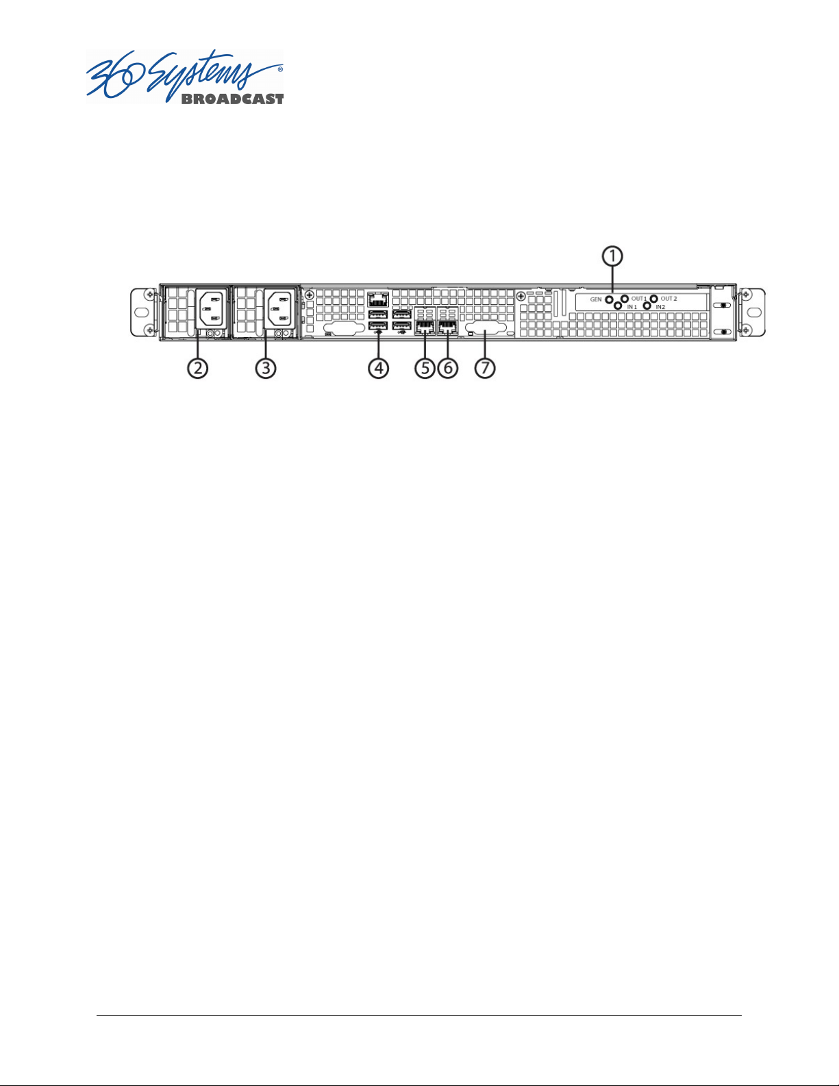
Figure 1 indicates the Rear Panel connections on TSS MINI Multi Format Video Server. Each
connection is described briefly in the following text. Make all connections appropriate to
other equipment before applying power to the system.
Figure 1 - Rear Panel Detail
Rear Panel Connections to the TSS MINI Multi Format Video Server
1. SDI Video I/O
2. Power Supply Module 1
3. Power Supply Module 2
4. USB ports for Keyboard / Mouse
5. Gigabit Ethernet port 1
6. Gigabit Ethernet port 2
7. VGA Video monitor output
SDI Video Inputs
TSS MINI Servers with input channel(s) will record digital video through the assigned HDBNC input(s) (High Density BNC) for either HD-SDI (serial digital per SMPTE 292M) or SD-SDI
(per SMPTE 259M).
Video Outputs
TSS MINI Servers with output channel(s) have assigned HD-BNC connections that can be
configured for HD-SDI operation (per SMPTE 292M) or SD-SDI operation (per SMPTE 259M).
Genlock Sync Reference
The TSS MINI Multi Format Video Server is designed to be referenced to an external genlock
source in the form of RS-170 black/burst, or Tri-level sync. The GENLOCK input provides a
Page 24 TSS MINI Operations Manual
Page 25

fixed 75-ohm termination. An internal crystal reference is also provided so that the server
can be used as a stand-alone player.
Gigabit Ethernet Port
A Gigabit Ethernet port is provided. Ports 1 and 2 may be used to access the server for the
transfer or retrieval of files. The 10GB Ports 1 and 2 are reserved for future use.
Keyboard
Attach the keyboard to an available USB port.
Mouse
A two-button scroll mouse is provided with the system. Plug the mouse into an available
USB port. Mouse operation can be reset by the keyboard sequence Control+Alt+F12 (the
screen will go black) followed by Control+Alt+F7.
Monitor
A compliant computer monitor may be connected to the video port directly using a VGA
cable. The resolution is automatically determined by the monitor connection. NOTE: The
monitor must be turned on and active before booting the server. If no monitor is detected,
the default screen resolution of 640 x 480 will be used. The GUI is best-viewed on 19-inch or
larger monitors. 360 Systems does not provide monitors for the server.
Serial Port
The rear panel serial port is not used. Make no connection.
USB Ports
The rear panel USB ports may be used to connect a keyboard, mouse or CXP-5 module. Do
not use a USB hub to operate the CXP-5 module.
Power Switch (not shown in Figure 2)
Shutdown the system only by momentarily pressing the front panel power button, or
through the SHUTDOWN command on the On-Screen user interface.
PRESSING THE FRONT PANEL POWER BUTTON FOR FOUR SECONDS WILL FORCE A
SHUTDOWN. USE THIS METHOD ONLY IF THE UNIT IS NOT RESPONDING AS DAMAGE TO
THE DATA ON THE RAID SYSTEM MAY RESULT.
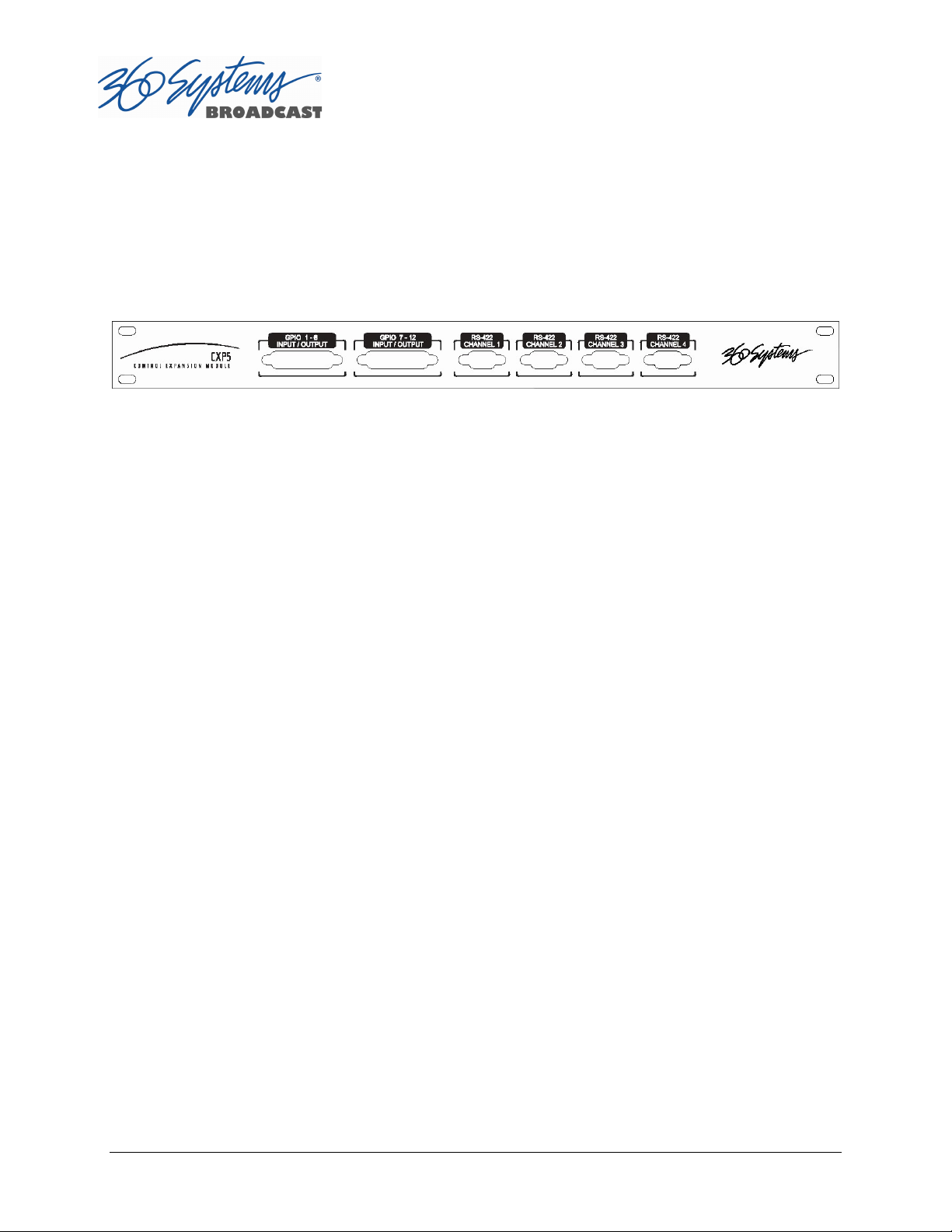
Serial Control Ports for Channels
Each of the four 9-pin “D” connectors on the CXP-5 module provides independent control of
the assigned video channel(s). They accept serial commands in VDCP, BVW or Odetics
protocol. The multiple serial ports allow simultaneous connection of an automation
controller and a desktop controller. See the chapter on Automation Control for further
details.
TSS MINI Operations Manual Page 25
Page 26
Most broadcast automation systems and some remote control panels employ VDCP
protocol. Many controllers used for transport, instant replay, and edit control employ BVW
or Odetics protocol.
Note that the server does not respond or provide status for all messages that are specific to
tape machines. As such it may not operate with editing systems designed for use with tape
machines.
Figure 2 – CXP-5 Module Connectors
GPIO Control
The CXP-5 module provides twelve GPIO inputs for control of machine functions, which
appear on two 25-pin GPIO connectors. These “General Purpose Inputs” can be connected
to switch contacts or to an open-collector transistor output. GPI inputs are programmable,
and can provide machine control such as PLAY, STOP, or RECORD through simple external
switches.
The CXP-5 also provides twelve GPIO Outputs which may be used to confirm that a
command has been received, to trigger operations on external equipment, or provide
warning indications for system errors. The function of these open-collector outputs is
programmable; they may be used to operate an LED, or they can drive a suitable logic input.
The pin-out for the GPIO connectors will be found in APPENDIX A.
Page 26 TSS MINI Operations Manual
Page 27

Basic Operations
This section introduces the Graphic User Interface (GUI), its menus and operating controls.
The graphic user interface is the primary way to manage server operations. With it, you can
control recording and playout, set up video and audio parameters, configure the network
and remote control ports, edit clips and make playlists.
The GUI is operated with a keyboard, mouse, and monitor connected to the server rear
panel. During the first power on the system must be connected to a keyboard, monitor
and mouse. The server will ask you to accept the Software Licensing Agreement before it
will operate. This screen will only appear during the initial startup.
The Server Desktop
The server desktop is similar to many computer graphic interfaces. A task bar and start menu
appear at the bottom of the screen. Use the Start menu button to launch applications,
manage the system or to shut down the server.
Launching the Graphic User Interface
The GUI launches automatically during start up. If it has been closed, click Start, then TSS
MINI GUI to re-launch it. The GUI window can be moved or minimized as desired.
Shutting Down the Server
Click Start, then Shutdown, to begin an orderly shutdown, or Full Restart to do an orderly
shutdown and restart (without a full power down).
Alternatively, momentarily pressing the front panel power button will cause the system to
begin an orderly shutdown. The server will acknowledge the button press with an audible
beep and the front panel lights will begin to flash together. Any operation in progress will
be halted, and any unsaved work will be lost.
In most cases the power will shut off automatically. However, if the front panel lights begin
to blink, it means that the file system has been properly closed, and it is safe to force the
power off by holding the front panel button in for 4 seconds.
If the system has stopped responding to commands and will not reset by pressing the front
panel button, press and hold the button for four seconds to force a power down. Wait 5
seconds, and then the system may be restarted with another press of this button.
DO NOT disconnect AC power to shutdown the server. Doing so may cause loss of unsaved
data, and may require the RAID drive array to re-synchronize – a process that could take
several hours. Shutdown the system only by momentarily pressing the front panel Power
button, or through the GUI.
The Quick Restart option in the Start menu allows the GUI and video playback application
to be restarted without restarting the entire operating system.
TSS MINI Operations Manual Page 27
Page 28

Graphic User Interface Overview
Once the server has successfully powered up, the VGA monitor will display the GUI of Figure 3.
This view provides:
A main System Menu bar for configuration operations
A Status Bar that displays various system messages
Three or four (Model dependent) VTR-like transport controls, one for each video
channel
Figure 3: Graphic User Interface with Clip Transport Windows
The input monitor will read Video In OK and display the received video resolution:
1080i, 720p, SD or NO INPUT.
When using the mouse, all buttons of all channels will operate immediately, without first
selecting a window to activate it. (Channel 1 is active in the illustration above, indicated by its
blue title bar.)
When using key commands, the active window is the only transport that will respond. Use
the CTRL+TAB key combination to change the active window in rotation, or use the mouse to
activate the desired window by clicking anywhere in it.
Page 28 TSS MINI Operations Manual
Page 29

Windows can be moved, resized and overlapped by dragging the title bar, window edges,
or the resize tab at the lower right corner of a window. The CTRL+TAB key combination will
also place the activated window in front of all other windows.
System Menu Bar
The System Menu bar contains four menus: Show, Edit, Windows and Help.
Show Menu
Contains selections for the Three or Four (Model dependent) Channels and the clip
management windows.
Channel Window Selection
Channel 1
Channel 2
Opens the specified window if it is closed, brings it to the top and activates it.
Key Commands – F1, F2
Clip List
Opens the Clip List window if it is closed, brings it to the top and activates it. See page
29.
Key Command – Ctrl+L.
Find Clips
Opens the Clip Locator dialog. See page 29.
Key Command – Ctrl+F.
Edit Menu
Contains a single selection, Configuration. This opens the main System Configuration
dialog. See page 35.
Windows Menu
Choices in this menu change the way the windows are displayed. Use the CTRL+TAB key
combination to change the active window in rotation, or use the mouse to activate a specific
window.
TSS MINI Operations Manual Page 29
Page 30

Cascade
Arranges all open windows so that they are overlapping, but offset. It is useful as a
starting point to rearrange the windows. This choice is especially useful with small
monitors.
Tile
Arranges all open windows so that each is fully visible. This choice is especially useful with
larger monitors. In case Windows do not tile as expected, select Cascade to restore their
original size and order, then select Tile.
In addition, there are selections for each open transport window. Selecting one of these
brings that transport to the top of the display and makes it the active window.
Help Menu
Contains a single item, About, which displays the server software versions, serial number and
Unit ID.
The Status Bar
A status bar appears at the bottom of the window that provides system information
including Server Status, GENLOCK, VIDEO INPUT, and TIME REMAINING—PERCENT FULL. Messages
such as CONNECTED TO HOST or CONNECTION TO HOST REFUSED are also displayed as diagnostics.
Error and status messages from the RAID system can also be displayed here.
Channel 1 can Record or Play video content. Channel 2 may Record or Play (2200) or may be
play only (2100), depending upon model. All channels may be used at the same time.
Each channel can be controlled in two different views.
The Transport View
The Playlist View
The Transport Channel View
The Transport Channel View is shown in Figure 4. This is the default view of each channel.
Basic transport operations such as play, stop, record, and head/tail trimming appear in the
Clip Transport window for each channel. These operate in familiar VTR fashion.
Page 30 TSS MINI Operations Manual
Page 31

Figure 4 - Transport Channel View
Transport Menu Bar
There are two menus, File and Options.
File Menu
New
Record capable channels only (Channel 1 and in some models Channel 2). Opens the Clip
List to allow naming of a new clip, then prepares channel 1 or 2 for recording.
See page Error! Bookmark not defined..
Key Command – Ctrl+N.
Open
Opens the Clip List to allow choosing a clip to load into the transport.
Key Command – Ctrl+O.
Save
Saves an edited clip using its existing file name.
Key Command – Ctrl+S.
Save As
Opens the Clip List to allow saving an edited version of the clip with a new name. This
allows making alternate versions of a clip or making multiple segments of a master clip.
TSS MINI Operations Manual Page 31
Page 32

Key Command – Ctrl+A.
Playlist
Switches from Transport View to Playlist View.
Close
Closes the Transport window. This has the same effect as the Close box in the upper right
corner of the window. Note that this will not stop playback or eject a loaded clip.
Options Menu
This menu contains two selections.
Take Control
Takes control of the video channel from another user (the Serial Control, a Remote
Workstation, or if you are using a Remote Workstation possibly the local GUI.) This item is
grayed out when the window has control.
Key Command – Ctrl+T.
Configure
Go To
Opens the video channel’s Configuration dialog. See page Error! Bookmark not
defined..
Key Command – Ctrl+C.
Opens the video channel’s Frame Locator. See page 46.
Key Command – Ctrl+G.
Page 32 TSS MINI Operations Manual
Page 33

Cue the selected
clip to play next.
Begin playing the next
(cued) clip immediately.
Cue the selected clip and
Display and Track the
Displays the time
Displays the time
next HOLD event.
Enable playlist editing.
Displays the time
Displays the current
Lists the clips
Eject the Playlist.
Stop the Playlist.
Play or Pause the
Repeat the Playlist indefinitely.
Set the
Check to arm
Start Time.
Insert a HOLD event
The Playlist Channel View
The Playlist Channel View is shown in Figure 5. This view allows multiple clips to be loaded in
a Playlist for sequential playout.
time of day.
scheduled
start time for
remaining of the
remaining before the
remaining for all
Scheduled
and events of
Playlist.
Figure 5 - Playlist Channel View
Playlist Menu Bar
There are two menus, File and Options.
clip that is currently
before the selected
File Menu
Open
TSS MINI Operations Manual Page 33
Opens the Playlist Selector to allow choosing a Playlist to load into the Playlist Window.
Key Command – Ctrl+D.
Page 34

Append
Opens the Playlist Selection dialog to allow choosing a Playlist to Append to the
currently loaded list. This can be done while playing to allow continuous playback of
new Playlists. See page Error! Bookmark not defined..
Save
Saves an edited Playlist using its existing file name.
Key Command – Ctrl+S.
Save As
Opens the Clip List to allow saving an edited version of the clip with a new name. This
allows making alternate versions of a clip or making multiple segments of a master clip.
Key Command – Ctrl+A.
Rename
Opens the Playlist Selection dialog to allow renaming the currently loaded Playlist.
Transport
Switches from Playlist View to Transport View. Only available when idle.
Eject
Ejects the currently loaded Playlist in preparation for creating a new one. (It is not
necessary to Eject a list to load another saved list. If the current list has been edited you
will be asked to save the changes.)
Key Command – Ctrl+N.
Close
Closes the Playlist window. This has the same effect as the Close box in the upper right
corner of the window. Note that this will not stop playback or eject a loaded list.
Options Menu
This menu contains two selections:
Take Control
Takes control of the video channel from another user (the Serial Control, a Remote
Workstation, or if you are using a Remote Workstation possibly the local GUI.) This item
is grayed out when the window has control.
Key Command – Ctrl+T.
Configure
Opens the Playlist’s Configuration dialog. See page Error! Bookmark not defined..
Note that this is different than the dialog for the video channel setup, which must be
accessed from the Transport View window.
Key Command – Ctrl+C.
Page 34 TSS MINI Operations Manual
Page 35

Initial System Configuration
Selecting a Sync Reference
In many applications, this server and downstream equipment connected to it must be
referenced to a common genlock source (SMPTE 170M or ITU-R-BT.470). A connector is
provided on the rear panel to receive a genlock signal (black and burst at the field rate of 25
or 29.97 fields/second) or a tri-level sync signal. It has a 75-ohm termination.
The genlock input automatically detects what type of input is connected. The frequency of
the reference must match the setting of the Frame Rate (see the next page).
An internal crystal reference is also provided so that the server can be used as a stand-alone
player when there is no need to synchronize with other equipment. Systems that
incorporate retiming circuitry in the router or video switcher inputs also may not require
referencing.
Note that the input sync for recording is derived from the input itself. This allows the
outputs to be timed while the input records an unreferenced signal.
Setting the Video Sync Source
To use with a referenced system, select External Sync using the GUI as follows:
Connect a source of genlock (black burst) or tri-level sync to the Genlock (or Reference)
input. Note that this may need to be connected while the unit powers up.
From the main menu bar select EDIT >CONFIGURE. Select the TIMING option. The
screen of Figure 6 appears.
Select EXTERNAL as the sync source.
Check that the front panel GENLOCK LED is now illuminated and the word GENLOCKED
now appears in the bottom right of the main GUI window.
Genlock Signal Quality
A genlock signal for the server must conform to one of the standards listed in the Technical
Specifications. An unstable genlock source may result in unwanted artifacts in the video output.
To use in a non-genlocked system, follow the instructions above but select INTERNAL
Sync.
TSS MINI Operations Manual Page 35
Page 36

29.97/(59.94) Frames(Fields)/Sec
25/(50)
1080i @ 59.94 Hz
1080i @ 50 Hz
720p @ 59.94 Hz
720p @ 50 Hz
Standard
NTSC
PAL
Input to the server is independent and self-clocking. It uses the input signal itself as a
reference. This allows recording any signal that conforms to the currently selected format.
No configuration is required to use this feature.
Selecting the Video Frame Rate Family
360 Systems TSS MINI servers can record and play video in four high definition video
formats and two standard definition formats: These formats are divided into two “families”
depending on the Frame (or Field) Rate that they are based on:
Frames(Fields)/Sec
High Definition
Definition
The rate is expressed in fps. 1080i and Standard Definition formats are interlaced and their
fields are displayed at the stated frequency; the frame rate is half that. The 720p
(progressive) format is more correctly referred to as a frames per second value.
To select a Video Frame Rate Family:
Go to Edit>Configure>Timing dialog on the GUI.
Select the button for the Frame Rate Family at which you will record or play.
A reminder will appear to stop video on all channels and restart to complete the transition to
the new frame rate.
Page 36 TSS MINI Operations Manual
Page 37

Figure 6 – Selecting a Frame Rate Family and Channel Output Format
The system as a whole operates at one Frame Rate Family at a time; it does not play clips of
mixed Frame Rate Families. Only the files recorded in the currently selected Frame Rate
Family will be visible in the Clip List. Files in the other format will become visible when the
server is set to that frame rate. Note that this also applies to any files you will be
transferring into the system; they must conform to the selected Frame Rate Family. The FTP
directory display will show all files on the system, so in the even that a clip of the wrong
frame rate is transferred it, it can be deleted by FTP without changing the system frame rate
setting.
Audio is recorded and played at the industry standard of 48 KHz sample rate (referenced to
the video frame rate), regardless of the video Frame Rate selected.
Selecting the Channel Output Format
Each of the system’s Video Channels are independently configurable to output 720p, 1080i,
or SD resolutions.
To select a Channel Output Format:
Go to Edit>Configure>Timing dialog on the GUI.
Select the button for the desired output format of each channel.
A reminder will appear to restart the system after a Channel Output Format has been
changed to complete the transition to the new format.
TSS MINI Operations Manual Page 37
Page 38

Making a Recording from the GUI
Video recordings are made using the Transport View of Channel 1 (2100) or Channel 1 & 2
(2200). These channels can record or play clips, but not both at the same time. On the 2100,
Channel 2 is playback only. The following steps are used to make a recording. Most
configuration settings can be skipped once a workflow is established. Channel 1 is used
below as an example; all instructions apply equally to channel 2 (Model dependent).
Record Configuration Options
If necessary, set Channel 1 and/or Channel 2 to the Transport View.
Click FILE >TRANSPORT in the Playlist View to switch to the Transport View.
Setting the Record Profile
Select OPTIONS >CONFIGURE from the Channel 1 Transport Window. The Dialog box in
Figure 7 appears. Click the arrow to open the dropdown menu to select a Record Profile.
AVC100 in .mxf (HD only)
o AVC Intra 100 in mxf
o Codec Type: H.264
o Bit Rate: 100 Mb/s
o Caption and VANC support via proprietary sidecar file.
o Audio Channels: 16
o Audio Codec: PCM
H.264 in .mp4
o HD or SD (480 line)
o MPEG 4 in .mp4
o Codec Type: H.264
o Bit Rates: HD 5-40 Mb/s SD 5-15 Mb/s
o Does not support Closed Captions
o Audio Channels: 2
o Audio Codec: AAC
MPEG2 PS 480 line in .mpg (SD only)
o MPEG Program Stream in .mpg
o Codec Type: MPEG2 Variable Bit Rate
o Bit Rate: Maximum selectable 5-50 Mb/s
o Does not support Closed Captions
o Audio Channels: 2
o Audio Codec: mp3 Layer 2
o Audio Codec: AAC
MPEG2 PS 512 line in .mpg (SD only)
o MPEG Program Stream in .mpg
o Codec Type: MPEG2 Variable Bit Rate
Page 38 TSS MINI Operations Manual
Page 39

o Bit Rate: Maximum selectable 5-50 Mb/s
o Supports Closed Captions
o Audio Channels: 2
o Audio Codec: mp3 Layer 2
IMX (D-10) in .mxf (SD only)
o IMX (D-10) in .mxf
o Codec Type: MPEG2 Constant Bit Rate
o Bit Rate: 30, 40, or 50 Mb/s
o Supports Closed Captions
o Audio Channels: 4
o Audio Codec PCM
Input Resolution Selection
Select OPTIONS >CONFIGURE from the Channel 1 (or 2 on 2200) Transport Window. The
Dialog box in Error! Reference source not found. appears.
Click the arrow to open the dropdown menu.
Select the Resolution of the input feed. The available resolutions will vary, depending on
the Record Profile Selected.
Click APPLY or OK.
Note: A warning will appear in the Transport Window if the selected Input Resolution does not
match the resolution of the input Feed.
Setting the Video Bit Rate
Select OPTIONS >CONFIGURE from the Channel 1 (or 2 on 2200) Transport Window. The
Dialog box in Error! Reference source not found. appears.
In the window, enter the desired Video Bit Rate (in Megabits/sec),. Alternatively, use the
up/down arrows to set a number. The range of values available depends on the Record
Profile selected.
Click APPLY or OK.
TSS MINI Operations Manual Page 39
Page 40

Figure 7 - Channel Configuration Dialog
Setting an Audio Delay Time
Audio tracks can be offset from video in 1 millisecond increments up to +/- one second. The
setting is per channel and non-volatile. It applies to playback only, not recording.
You must stop and start the playback to hear the result of a change. This adjustment is
made in Transport mode; once set it also applies to Playlist mode on that channel.
Select OPTIONS >CONFIGURE>OUTPUT from the Channel Transport Window. The
Dialog box in Figure 8 appears.
Enter a time offset value in the window.
Click APPLY or OK.
Figure 8 - Audio Delay Time Offset
Page 40 TSS MINI Operations Manual
Page 41

Audio Output Sync Reference
The audio sample rate is derived from the selected video sync reference. Audio is recorded at a
48K sample rate. The 0.1% pull-down for 59.94 Hz video is taken into account when generating
the sample rate.
Selecting a Time Code Source
When in High-Definition modes the server utilizes the time code standard specified in
SMPTE 12M-1, and applies it as described in SMPTE 12M-2. It is suggested that the user
refer to these documents, as HD time code differs significantly from standard definition
methods.
This function selects the source for time code for new recordings. The time code value
obtained from the selected source will be applied from the beginning of a recording.
Select OPTIONS >CONFIGURE from the Channel 1 Transport Window. The Dialog box
in Error! Reference source not found. appears.
The default Time Code Source is MANUAL. Alternatively, ATC (Ancillary Time Code ) or
TOD (Time Of Day as set by the system clock) may be selected.
For MANUAL, enter a time value in the window for the first frame of the recording. Use
the HH:MM:SS:FF format. It is not necessary to enter the colon ( : ) between digit pairs.
Click APPLY or OK.
Beginning Recording
When the setup steps outlined above are complete, you are ready to record. Place Channel
1 in the Record Ready mode as follows.
There are two approaches to starting a recording: “named recording” and “crash recording”.
You can name the clip first, then press Record; or just start recording, and let the system
generate a clip name automatically. The clip may be renamed as desired when the recording
is complete. The advantage of the first approach is that when the recording is complete, it is
fully identified and ready for use; the second approach is valuable for live action such as
sports, where there is no time to lose and action must be captured at once.
Clip names for crash recordings are of the form “new MMDD_N”, where MMDD represents
the month and day of the recording, and N is the lowest non-zero number that does not
cause the name to conflict with any previously made recording.
Making a Crash Recording
Press Record whenever Channel 1 reports that it is IDLE.
TSS MINI Operations Manual Page 41
Page 42
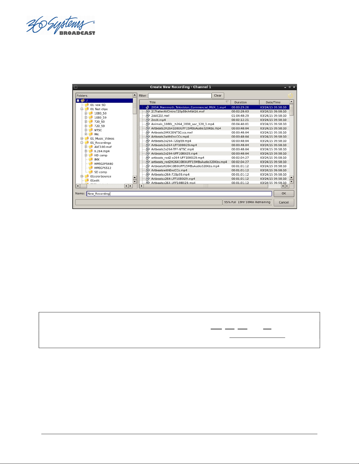
Making a Named Recording
From the Channel 1 Transport Window, Select FILE>NEW. The dialog of Figure 9 below
appears.
Figure 9 - Channel 1 Create New Recording dialog
Enter a clip name using the keyboard. Up to 115 characters may be used. Spaces are
allowed; however, some characters other than upper or lower case letters and numbers
may not be used. These characters will not enter into the name field when typed. They
include * ( ) + = ; : ‘ “ < > , . / and ? A list of existing clips will appear in the large
window, and can be used as a name reference when creating new clip names.
The Channel 1 transport Window will display the words IDLE CUEING for two seconds or
less. When ready to record, the Channel 1 Transport Window will display IDLE READY.
Note: File naming is case sensitive. Upper case letters sort before lower case. The name FILE
sorts in the order shown, based on differing capitalization: FILE, File, fiLe, and file. When using
the server with automation systems or other remote controls, it is not a good practice to
distinguish files only by differences in case.
Page 42 TSS MINI Operations Manual
Page 43

Figure 10 - Channel 1 Ready to Record
Click the RECORD button at any time to begin recording. The yellow time display counter
will update the clip duration continually.
To stop recording, click STOP.
Monitoring a Recording Source with Input Feed (E-E) Mode
The E-E button appears in the Channel 1 and Channel 2 (model dependent) Record/Play
window. It allows the input signal to be monitored from the server output. E-E Mode
toggles automatically as described below, but can also be switched manually at any time.
When a new clip is created for recording, the input source is automatically switched ON to
the output—an E-E connection. When a clip is opened for play on Channel 1 or 2, E-E
monitoring is switched OFF. (The term E-E comes from “Electrical to Electrical”.)
When Channel 1 or 2 is switched to playlist mode, the E-E monitor is switched OFF. E-E
mode cannot be toggled while the channel is in playlist mode.
When E-E is ON, the input video signal is routed to the outputs. Manually toggle the E-E
mode button OFF to switch the output to the servers output, for conventional playback
operation.
Under automation control, Auto E-E behavior is slightly different than under GUI control.
The server will remain in E-E ON mode until a transport control command (Play, Stop, Jog,
etc) is received. After receiving such a command, the server will remain in E-E OFF mode
until record mode is entered. In record mode, E-E mode is ON. As with GUI operation,
automation controllers may send E-E ON and E-E OFF commands to override the automatic
operation.
Note that when in E-E mode the video outputs are timed to the genlock signal. This allows
use of the input as an on air source when connected to other referenced equipment, even
TSS MINI Operations Manual Page 43
Page 44

when the input itself is not referenced. For example, you can simultaneously broadcast a live
signal while recording the event for later rebroadcast.
All VANC lines are passed through E-E regardless of which lines are selected for recording.
Similarly, all embedded audio is passed through even though (depending on the selected
recording format) only the lowest-numbered channels are recorded.
Page 44 TSS MINI Operations Manual
Page 45

Playing a Clip from the GUI
Video Playback can be done on all channels, individually or simultaneously. The recordcapable channels (Model dependent) can record or play, but not both at once. Follow these
steps to play a clip:
Beginning Playback
1. Select FILE >OPEN from the Transport Window of Channel 1 or 2. The Select Clip
windowError! Reference source not found. appears.
2. Navigate the folder structure if necessary by clicking on the folders.
3. Select the clip to be played by double-clicking it.
4. When the Transport Window indicates Idle Ready, the clip can be played by clicking
PLAY.
Figure 11 – Channel-1 Select Clip Window in “Open” Mode
Drag and Drop clip selection
1. Select FILE >CLIP LIST from the Main Window. The Clip List window in figure 11
appears.
2. Navigate the folder structure if necessary by clicking on the folders.
3. Select the clip to be played by clicking and holding the left mouse button. Wait briefly
then while continuing to hold the button “drag” the clip to the transport window and let
go.
TSS MINI Operations Manual Page 45
Page 46

4. When the Transport Window indicates Idle Ready, the clip can be played by clicking
PLAY.
Looping a Clip
Clicking on the LOOP checkbox in the Transport View will cause a clip to loop until LOOP is
unchecked, or until STOP is clicked. LOOP may be checked or unchecked before or during
playback, but must be changed at least 2 seconds before the end of clip to take immediate
effect.
Pausing a Clip
Click PAUSE at any time to pause a clip. Click again to resume. The PAUSE button is the
same key as the PLAY button.
Ejecting a Clip
Ejecting a clip effectively removes it from the transport. The channel will output Black.
Press EJECT to eject a clip.
Using Jog
The JOG + command will move to the next frame and go to Still.
The JOG – command will move to the previous frame and go to Still.
Using Go To Location
Click the arrows |< or >| to go to the next trim point (Mark In or Mark Out) in the selected
direction. When in Edit mode, an additional click in the selected direction will go to the
actual beginning or end of the entire clip.
To use the Go To Location slider, either select Go To from the
Options Menu of the Transport you are using, or type
Ctrl+G with the desired Transport selected (click anywhere
in the Transport window to select it - its title bar will turn blue.)
Using the mouse, drag the slider to move rapidly through the
video file. Or, type a specific frame location into the Destination field. You can type just as
much of the location as necessary, by typing frames, seconds and frames, minutes and
seconds and frames, or hours and minutes and seconds and frames. (You can type the
colons but they are not required.) Press Enter when done. The video will jump to the
specified frame (if it exists) and the Destination Field will become selected again to allow
another location to be entered.
Page 46 TSS MINI Operations Manual
Page 47

Using Fast Forward / Rewind
>> (Fast Forward) and << (Rewind) buttons transport program material at high speed in the
chosen direction. Four speed choices are available in each direction. Click the button
repeatedly for: 4x, 16x, 64x, and 128x. Audio does not play at any speed beyond +2X/-2X.
Slow Motion Playback
The TSS MINI system will play smooth slow-motion video in forward or reverse, at any speed
from zero to 2X forward or 2x reverse. Direction can be instantly changed, using either the
GUI or a desk-top controller. Audio is also played at these lower speeds. At speeds beyond
+2X/-2X, video frames will selected as needed, yielding a chunky result; audio is muted at
high speeds. Most slo-mo playback for sports and other uses lies well within the +2x/-2x
zone.
To play in slow motion from the GUI, press PLAY and then move the shuttle slider to the
desired speed. When you let go of the slider it goes back to pause. You can also have the
speed control “stick” at a particular speed – see below. See the following section for details
on the Shuttle control. For faster playback from the GUI, use the FAST FORWARD or REWIND
buttons as described in the preceding section.
In sports, slow-motion control is usually accomplished with a desk-top slow-mo controller,
such as those made by DNF Controls and others. These provide a hands-on experience far
preferable to using the GUI.
Using Shuttle to Control Playback Speed
The Shuttle Control is a slider bar that controls playback speed. Playback speed control
employs varispeed algorithms that may skip frames. It is not a perfect fast motion
mechanism.
The center position represents zero speed, or Still.
The right and left extents of the slider represent +2X/-1X maximums.
The Shuttle control slider works in three basic ways: Snap-Back to still, Hold Speed, and
Mouse Wheel.
In Snap-Back operation, click and drag the slide control to change speed. Releasing the
slider bar will let it snap back to zero speed, or still.
For Hold Speed operation, position the cursor over the slider control scale (not the slider
arrow) and click the left mouse button to increment the speed control. The transport will run
TSS MINI Operations Manual Page 47
Page 48

in the selected direction at the selected speed without holding the mouse button down. The
cursor may now be moved over the Stop button to wait for the desired point.
When using a wheel mouse, position the cursor over the slider scale and rotate the wheel to
increment speed. Rolling the wheel in opposite directions changes the direction the arrow
slider moves. To stop video, click the Stop button or the arrow slider.
Page 48 TSS MINI Operations Manual
Page 49

Editing a Clip
Edit controls are activated with the Edit check box. Several buttons are available to define
the beginning and end of a region within a clip; associated time code displays are also
present.
These non-destructive Mark In and Mark Out trim points can be set to define a portion of a
clip to be played. These “edit pointers” do not create a new clip from the original material;
they act like virtual trims, and material outside of the trim points is excluded, but can be
retrieved by resetting the Mark pointers. After setting the Mark In and Mark Out points,
clips will play between these points. These edit values are saved with the clip.
Edits may be saved to the current clip by de-selecting the Edit check box, or choosing Save
from the clip window File menu. Save As works to save the edit points to a new clip name,
even if the edits have not been saved in the current clip.
Marking the IN point
Sets the current time code value into the Mark In point time display. The Mark In button
can capture a time code value from the clip when it is still, or on-the-fly.
Mark In Display
Displays the time code of the Mark In point. When no Mark In point has been set manually,
this displays the Start of Message (SOM) time code (usually 00:00:00:00).
The values in this display window may be set by two methods:
Enter Mark In point from the keyboard: Use the mouse or Tab key to move between In
and Out fields. When a field is highlighted, enter a numeric value from the keyboard.
Whether a clip is still or playing, press Mark In to capture a time code value from the
clip’s current position.
Marking the Out Point
Sets the current time code value into the Mark Out point time display. The Mark Out
button can capture a time code value from the clip when it is still, or on-the-fly.
Mark Out Display
Displays the Mark Out point time code. When no Mark Out point has been set manually,
this displays the EOM time code (originally the end time of the recording).
The values in this display window may be set by two methods:
TSS MINI Operations Manual Page 49
Page 50

Enter Mark Out point from the keyboard: Use the mouse or Tab key to move between In
and Out fields. When a field is highlighted, enter a numeric value from the keyboard.
Whether a clip is still or playing, press Mark Out to capture a time code value from the
clip’s current position.
Duration Display
Displays the total running time (TRT) of the current clip. TRT is defined as the difference in
the time codes between the first and last frames, plus one. For example, if the first frame of
the clip is 00:00:00:00 and last frame displayed at the end is 00:00:01:15, the reported
duration will be 00:00:01:16.
With 59.94 Hz drop-frame time code, the true play duration may not be the exact numerical
value of ((Mark Out – Mark In) + 1) due to the discontinuities in the drop-frame time line.
The true run time is shown in the Clip List.
Auditioning the Mark In Point (Review Edit Button)
|
|
The Review Edit button
<~>
cues the clip to the Mark In point (or SOM, if no Mark In
point exists) and begins playback. Review Edit will stop at the Mark Out point. The Mark
Out point will be displayed in Still mode.
The Review Clip button may be used to check the Mark In point without playing all the way
through the clip. After Review Clip is pressed and play begins, all of the standard transport
buttons are available for use.
Auditioning the Mark Out Point (Review Tail Button)
|
The Review Tail button
~>
may be used to audition the Mark Out point without
playing all the way through the clip. It will cue the clip to three seconds before the Mark Out
point (or EOM, if no Mark Out Point exists) and then begin playback. Review Out will stop at
the Mark Out Point.
Single-Frame Clips
It is possible to Click Mark In and Mark Out on the same frame to create a still frame for use
in a playlist. These can function as either a hold point in the list that will display the frame
until another action is taken, or they can be assigned a duration. See page Error! Bookmark
not defined. for information on setting the duration of a still frame in a playlist.
Page 50 TSS MINI Operations Manual
Page 51

System Configuration
The following configuration options apply to the server as a whole, except where it applies
specifically to an individual channel.
Assigning Names to the Server and Transport Channels
The server can be assigned a name that will be displayed along the top of the Main GUI
Window. Each individual server channel can also be given a name.
To assign a name to the server or transport channels, click EDIT>CONFIGURE>NAMES
from the main menu pulldown.
The screen of Error! Reference source not found. is displayed. Use the keyboard to type in
a name for any of the selections. Names can be up to 31 characters in length. Spaces, digits
and other non-alphanumeric characters may be used. Click APPLY to accept the name. The
names will appear in their appropriate windows immediately.
Figure 12 - Configure Names Screen
TSS MINI Operations Manual Page 51
Page 52

Programming GPIO Outputs
The system has twelve General Purpose Outputs, referred to as GPO 1 through 12. Each can be
programmed to go active on the selected channel when one of the following events occurs:
IDLE
PAUSED
STOPPED
PLAYING
RECORDING
Transport returns to idle
Transport is paused
Transport is stopped
Transport is playing
Transport is recording
PLAYLIST
RAID Fault
NO GENLOCK
NO VIDEO INPUT
Fan Fault
System Fault
Any Fault
To program a GPO output, select EDIT >CONFIGURE >GPO. The screen of Error! Reference
source not found. is displayed. GPO 1 through 12 are triggerable outputs. The checkboxes to
the right of each selection represent channel 1 and channel 2.
To activate one of the GPO, pulldown the event menu and select which event will
activate the GPO.
Select an associated channel where applicable by checking the channel checkbox.
Click APPLY to activate.
Control GPO via playlist (or Playback Schedule)
RAID Fault
No genlock
No video at the selected input
Fan Fault
System Fault
RAID, Fan or System Fault
Page 52 TSS MINI Operations Manual
Page 53

Figure 13 - GPO Configuration Screen
Programming GPI Inputs
The optional CXP-5 module has 12 General Purpose Inputs, referred to as GPI 1 through GPI 12.
Each can be programmed to trigger one of the following events on a channel:
CUE
JUMP
NEXT
PAUSE
PLAY
RECORD
SELPREV
SELNEXT
STOP
Cue a clip (in a Playlist or Playback Schedule)
Cue selected clip for immediate playback (Playlist Mode only)
Immediately plays next cued clip in a playlist for playback
(Playlist Mode only)
Pause a clip
Play a clip
Start a recording
In Playlist Mode – Navigate to clip above currently selected clip
In Playlist Mode – Navigate to clip below currently selected clip
Stop a clip
To program a GPI Input, select EDIT >CONFIGURE >GPI. The screen of Error! Reference source
not found. will be displayed. GPI 1 through 12 are programmable inputs. The checkboxes to the
right of each selection represent video channel 1 and channel 2.
1. To activate a GPI input, select the event from the pulldown the event menu
TSS MINI Operations Manual Page 53
Page 54

2. Mark a checkbox for the channel of interest. The event will be triggered when that GPI
goes active.
3. Click APPLY to activate.
Figure 14 - GPI Configuration Screen
Configuring the Ethernet Network
The system provides a number of user settings that configure it for use in a practical
network. These will be found on the Configure Network tab shown below.
The NET-1 Ethernet port on the server has a unique IP Address. In this way, each server can
be identified on the network.
Network Settings Tab
Use the Main Menu selection bar at the top of the server GUI to configure network
communication settings.
Click EDIT >CONFIGURE >NETWORK
The screen of Figure 15Error! Reference source not found. is displayed.
Page 54 TSS MINI Operations Manual
Page 55

Figure 15 - Network Configuration Screen
The server is shipped with a default network Host Name and IP Address. Qualified network
engineers may change these configurations to suit your specific network environment. Factory
defaults for networking are:
Network Disabled
Use DHCP
Disable Network [X]
This selection turns the network OFF or ON. The default is Disabled (the box is checked). To
Enable the network connection, click the box to un-check it. Disabling the network can be
used to deny access to the server from the network for security purposes.
Enabling/Disabling DHCP [X]
Enabling DHCP will configure the network interface automatically.
If the DHCP box is not selected, the user may then manually enter assignments in the
following windows:
IP Address ( Example: 192.168.1.20 )
Net Mask ( Example: 255.255.255.0 )
Default Router ( Example: 192.168.1.1 )
The Host Name and NTP domain name may be a fully qualified domain name, such as
edit1.mydomain.com. All other manually configured addresses must be properly formatted
IP addresses.
TSS MINI Operations Manual Page 55
Page 56

FTP User / Password
In this space, you may set the User Name and Password to be used to access the system
remotely via an FTP client.
Saving Network Configuration
Click on OK, APPLY, or CANCEL to accept or abandon new entries.
The IP address of the system is displayed in the center of the GUI at the end of the main
window title.
IMPORTANT
The server is designed to be used in a private dedicated video network. An
external firewall (preferably with Virtual Private Network (VPN) support) must be
used in systems that require internal security or are connection to public networks.
Consult with a network security specialist for guidance on the best hardware,
programming and practices for your facility’s requirements.
Page 56 TSS MINI Operations Manual
Page 57

Setting the Date and Time
Click EDIT >CONFIGURE >DATE/TIME. The dialog below appears.
Figure 16 - Time/Date Configuration Screen
Set the TIME and DATE by clicking on the Time/Date field and navigating the clock and
calendar.
Check Automatic Updates to enable automatic updates using the Network Time Protocol
(NTP). Refer to Network Time Protocol on page 86.
TSS MINI Operations Manual Page 57
Page 58

Figure 17 - Time/Date Configuration Screen
Select the REGION and ZONE according to your geographic location or time zone. Use the
scroll-bar as necessary, and then click on the desired value.
Note: A System Restart is required for a Time Zone change to take effect
Page 58 TSS MINI Operations Manual
Page 59

Clip List
The TSS MINI server’s Clip List is used to find, select, delete, name, and rename clips.
Clips can be dragged and dropped anywhere on a Transport for immediate playback.
Single or multiple clips can be dragged into a Playlist. See page 67.
Click SHOW >CLIP LIST from the main pulldown menu to display the Clip List.
Figure 18 – Clip List
Renaming and Deleting Clips
Clips can be renamed by right clicking on them with the mouse, then selecting Rename from
the pop-up menu.
Clips can be deleted by right clicking on them with the mouse, then selecting Delete from
the pop-up menu.
Sorting Clips
Clips can be sorted in forward or reverse order by any of the columns by clicking once or
twice on the column heading. The previous sort is maintained, so if the sort is by Name, then
by Date, the clips of each Date will be sorted by Name.
TSS MINI Operations Manual Page 59
Page 60

Filtering the Clip Display
You can limit the number of clips displayed by typing a string in the SEARCH FILTER field.
For example, typing “AT” in the filter field limits the display to all clips that contain “AT”
somewhere in the clip name. It is not case sensitive, AT will show At, aT and at as well.
Pressing the Clear button restores the complete display.
Finding Clips
Clips can be easily found using the Clip Locator. To locate a clip:
1. Click SHOW>FIND CLIPS. The Clip Locator screen of Error! Reference source not
found. appears.
2. Check Case Sensitive to make the search case-sensitive.
3. Check Stop After First Match to find only the first match.
4. Check Use Regular Expressions to search for the string of interest ANYWHERE in the
clip name. With Regular Expressions unchecked, the search will match only clips that
BEGIN with the string entered at FIND. See the next page for more on Regular
Expressions.
5. Optionally, Enter a string in the SEARCH FILTER field to limit the number of clips
displayed. For example, entering “AT” in the SEARCH FILTER field will limit the display to
only clips containing “AT” in their clip name. Pressing the Clear button restores the
complete display.
6. Enter a name or part of a name in the FIND field. Press Enter to initiate the search.
The clip(s) will be displayed according to the rules set by the checkbox settings.
Page 60 TSS MINI Operations Manual
Page 61

Figure 19 - Clip Locator
Finding Clips Using Wildcards
The following wildcard conventions may be used in a search when Use Regular Expressions is
unchecked.
* Match anything. For example, to find all clips starting with “xyz”, use the pattern
“xyz*”. To find all clips containing “2008” use “*2008*”.
? Match any single character.
TSS MINI Operations Manual Page 61
Page 62

Finding Clips Using Regular Expressions
A regular expression (“RE”) specifies a pattern to be matched in a clip name. Regular expressions
can contain both special and ordinary characters. Ordinary characters just match themselves.
Thus, the RE “night” would match the “night” in the clip name “Tonight Show”, so this and any
other clip name with “night” in it would be placed in the list of found clips.
The following special characters are supported:
. (dot) This matches any single character. “a.c” matches “abc”, “aac”, “a2c” and “a c”
but not “acd”.
^ (caret) This matches the start of a clip name. To find all clips starting with “xyz”, for
example, use the Regular Expression “^xyz”.
$ Match the end of the clip name. To find all clips ending in “xyz” use the RE “xyz$”.
< Match the beginning of a word. For example “<Show” will match all clip names
containing a word that starts with “Show”, such as “Now Showing”, but not “LateShow”.
> Match the end of a word.
* Match zero or more repetitions of the preceding character. “.*” will match anything
– “G.*N.*” will match “Georgia Evening News” or “Good Night”.
+ Match 1 or more repetitions of the preceding RE term. “0+” matches 00 or 0000, not 0.
? The preceding Regular Expression term is optional. “ab?c” will match “ac” or “abc”
but not “adc”.
[ ] Used to indicate a set of characters. Characters can be listed individually, or a range of
characters can be indicated by giving two characters and separating them by a "-".
Special characters are not active inside sets. For example, [a+$] will match any of the
characters "a", "+", or "$". [a-z] will match any lowercase letter. [a-zA-Z0-9]
matches any letter or digit. If you want to include a "-" inside a set, precede it with a
backslash (“\-“), or place it as the first character. You can match all characters that are
not within the set by making "^" as the first character of the set; "^" elsewhere will
simply match the "^" character. For example, [^7] will match any character except
"7".
SPACE A space is treated as an ordinary character. “ Show “ (<space>Show) will match
“Tonight Show” or “Now Showing” but not "NewShow”. “ “ will match any clip with a
space in the name.
Page 62 TSS MINI Operations Manual
Page 63

The subject of Regular Expressions is much larger than can be completely covered here. They
are used in several different operating systems and programming languages. Further
information can be found on the internet and in books on Regular Expressions and Linux.
TSS MINI Operations Manual Page 63
Page 64

Using Playlists
The TSS MINI Multi Format Video Server’s Advanced Playlisting software provides extensive
tools for building, editing and playing complex sequences of program content. Advanced
Playlisting appears as on-screen windows, with an intuitive Graphic User Interface that makes
it easy to operate without extra equipment. It’s invaluable for building commercial breaks,
news rundowns, still-store and clip lists. The server will create and store as many playlists as
needed, each with its own unique name. For many users, Advanced Playlisting may be all
that’s needed to go to air.
The following features are included:
Drag-and-drop playlist building and editing on a graphic interface
Edit lists while they’re running
Start at any point in a list
Displays run time for clips, plus segment length and total remaining time
On-the-Fly commands for Pause, Skip, Hold, Next and Jump functions
Append a playing list with a saved playlist
Up to 12 programmable GPI Output events embedded in playlist clips
Programmable time-of-day start for a playlist and for individual events
Generates an As-Run Log
Setting rules for deleting old playlist entries
Simple text format allows playlists to be created, viewed and edited offline
FTP access allows playlists to be transferred between servers, or to/from a PC
For information about the playlist and asrun file formats, external list editing and use with
traffic systems, see Appendix D on page 132 and Appendix E on page 135.
Page 64 TSS MINI Operations Manual
Page 65

The Playlist View
Cue a clip to
Cue the next clip and
Cue the selected clip
Insert a HOLD event
Display and Track the
clip
Displays the time
Displays the time
Enable playlist editing.
Displays the time
Displays the current
Lists the clips
Stop the Playlist.
Play or Pause the
Repeat the Playlist indefinitely.
Displays a
Check to arm
The playlist view for channel 1 is shown in Error! Reference source not found.. Its functions
are briefly described here. Table 1 provides an overview of Playlist control functions and
their associated hot-keys.
time of day.
scheduled
start time for
a playlist.
remaining of the
current clip or event.
remaining before the
next HOLD event.
remaining for all
events to finish.
Scheduled
Start Time.
and events of
the Playlist.
Playlist.
begin playing
play next.
Figure 20 - Channel 1 Playlist View
and begin playing
that is currently playing.
Eject the Playlist.
before the selected
event.
TSS MINI Operations Manual Page 65
Page 66

FUNCTION
DESCRIPTION / REFERENCE
INVOKE
HOT
-
KEY
PLAY/ PAUSE
Play / Pause a clip ( Page
69
Error!
Button
STOP/ SHOW
Stop / Show First Frame ( Page
69)
Button
CUE
Cue a clip ( Page
Error! Bookmark not
Button
NEXT
Prepare next clip for playback ( Page
70)
Button
JUMP
Jump to the selected clip ( P
age
70)
Button
LOOP
Check to loop a Playlist ( Page
70)
LOOP
EDIT
Check to enable editing ( Page
73)
EDIT
ARM START
TIME
HOME
PLAY
Bookmark not defined.)
STOP
CUE
defined. )
NEXT
JUMP
Checkbox
Checkbox
Enable Scheduled Start Time ( Page 70)
Scroll to currently playing Clip ( Page 71) HOME Button
Table 1 - Playlist Control Functions
ARM
START TIME
Checkbox
P or
SPACE
S
C
N
J
L
E
T
H
Page 66 TSS MINI Operations Manual
Page 67

Creating and Running a Playlist
To Create a Playlist (Using Channel 1 in the example):
1. Change the transport for Channel 1 to the Playlist View. Click FILE
>PLAYLIST in the Channel 1 transport pulldown menu. The window of Error!
Reference source not found. appears.
2. Click the EDIT check box to put the channel into edit mode.
3. Click SHOW >CLIP LIST from the main menu to open the Clip List. Both
windows are now visible.
4. Insert clips in the list using one of these methods:
Double click on a clip in the Clip List to add it to the Playlist. The clip will appear
in the playlist. The first clip will indicate a status of CUED. Note that this mode of
insertion can only work when one channel is in Edit mode.
Alternately, click on any clip and hold the mouse button as you move the cursor
to the playlist. Let go of the button when the cursor is over the position that you
want the clip to appear in the playlist (drag and drop).
You can drag and drop a single clip from one playlist to another by holding the
Control key while you select and drag the clip. (Both lists must be in Edit mode.
You can duplicate a playlist entry within the same playlist by dragging it while
holding the Control key.
5. Repeat the procedures to add more clips.
TSS MINI Operations Manual Page 67
Page 68

Figure 21 - Channel 1 Playlist with Clip List
6. Click PLAY to run the playlist. The clips will be played in the order they were
entered in the playlist. The currently playing clip will indicate a status of
PLAYING. The next clip on the list will indicate a status of CUED.
7. To SAVE the Playlist select FILE >SAVE-AS. Enter a file name. Click SAVE.
8. To SAVE an existing playlist without changing the name, use FILE >SAVE.
Page 68 TSS MINI Operations Manual
Page 69
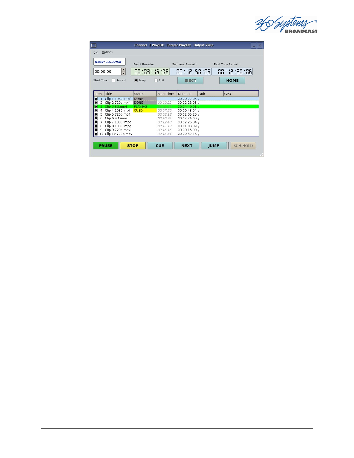
Figure 22 – Active Playlist
Loading a Playlist (FILE>OPEN)
Click FILE >OPEN from the Playlist View to bring up the list of available Playlists. Doubleclick on a playlist to load it.
Saving a New Playlist (FILE>SAVE AS)
Once a Playlist has been created, it can be saved by selecting FILE >SAVE AS from the
Playlist View pulldown menu. Type in an appropriate name and click SAVE.
Saving an Existing Playlist (FILE>SAVE)
An existing Playlist can be saved by selecting FILE >SAVE from the Playlist View pulldown
menu. Type in an appropriate name and click SAVE.
Stopping a Playlist (STOP)
Click STOP to halt a Playlist.
Pausing Playlist (PLAY/PAUSE)
When a Playlist is running, the PLAY key will change to indicate PAUSE. Pressing PAUSE
stops the Playlist immediately, on the current frame of a clip. Pressing it again will resume
playback.
TSS MINI Operations Manual Page 69
Page 70

Cueing a Clip (CUE)
When the Playlist is running, click CUE to immediately prepare a selected clip for playback.
When the current clip is finished playing, the Playlist will play the Cued clip, followed by all
subsequent clips. This allows the user to skip over clips that appear in the list between the
currently playing clip and the selected clip.
The user may also re-cue a clip that has already been played. In this case, the Playlist will
restart from the selected clip, and all subsequent events will be played (or re-played) in
sequence. When the Playlist is stopped, CUE will prepare the selected clip to play when Play
is pressed, or the list is started automatically by Arm Start Time.
Looping Playlist (LOOP [X] )
To loop the entire playlist after the last clip completes, check the LOOP checkbox at any
time. Upon un-checking, the list will play to completion and then stop.
Showing First Frame of CUED Clip (SHOW)
When a clip is cued, the STOP button legend changes to SHOW. Pressing it will display the
first frame of the cued clip.
Preparing Next Clip for Playback (NEXT)
When a Playlist is stopped, click NEXT to prepare the next clip in the Playlist for playback.
While the Playlist is running, NEXT will immediately begin playing the next cued clip in the
Playlist. (The next clip may require several seconds to load and cue for a seamless transition.)
If the next event in the Playlist is a HOLD, the NEXT command will move to the Hold event,
and video will Go to Black between Clips, Show First Frame of Next Clip or Hold on Last
Frame of Clip, depending on Hold Behavior selected.
Jumping to Selected Clip (JUMP)
Click JUMP to cue any selected clip for immediate playback; this permits jumping over
intervening clips. JUMP also allows clips that have already been played to be immediately
re-cued and played. In this case, the Playlist will restart from the selected clip, and
subsequent events will be re-played in sequence.
Setting Playlist Start Time
Set a start time for a Playlist by entering a twenty four hour time of day in Hours, Minutes
and Seconds in the START TIME field (see Error! Reference source not found. Figure 20
on page 65). Click on any field to edit the field. Check the ARM START TIME checkbox to
arm the start time. The ARM START TIME checkbox will automatically uncheck itself once
the playlist has started.
Page 70 TSS MINI Operations Manual
Page 71

Triggering the Start Time is essentially the same as pressing the Play button, so it is
possible to arm the start time while a list is playing, have the playback stop from a Hold or
GPI Stop, and then restart when the Start Time triggers playback.
Automatic Scrolling to Currently Playing Clip (HOME)
Click HOME to make the currently playing clip visible in the Playlist View window. If no clip is
playing, then the currently-cued clip is displayed. This is helpful if you have manually scrolled
elsewhere in a large Playlist. Once this is done, the display will also maintain the currentlyplaying clip within the window, if EDIT is off
Set HOLD Behavior
This determines what happens during a HOLD:
Click OPTIONS>CONFIGURE from the Playlist View of the channel pulldown. Use the drop
down menu to select between Go to Black between Clips, Show First Frame of Next Clip
or Hold on Last Frame of Clip.
A hold can exist not only when there is a HOLD event in the list, but also because the next
clip to play has a scheduled start time.
Note when using Hold on Last Frame or Show First Frame of Next Clip, you can still go to
black at any particular point in the playlist by inserting a still or single frame clip of black.
Figure 23 - Configure Channel 1 Playlist Window
Set Maximum Number of Items to Keep
To set the number of played items to be retained in a playlist:
TSS MINI Operations Manual Page 71
Page 72

Click OPTIONS>CONFIGURE from the Playlist View of the channel pulldown. Use the
thumbwheel UP and DOWN scroll button to increase or decrease the number of clips to
retain. The default value of zero will retain ALL Items. Note that this only applies to the
playlist itself, the actual clips referenced are not deleted.
Enabling As-Run Logging
To enable As-Run logs, while in the Playlist View select OPTIONS >CONFIGURE from the
menus within the Playlist window. Check the Enable As-Run Logging checkbox to enable
As-Run logging. Uncheck the box to disable As-Run logging. When enabled, a check mark
will appear next to the As-Run log label, and files played by a playlist will be written to an
As-Run log. As-Run logs are available only through FTP downloads; they cannot be viewed
or printed from the server. After logging into a server, select the ASRUN folder. All logs are
stored in this location, and have the extension “.arl”. Refer to Appendix E – As-Run Logging
for more details about As-Run logging functionality.
Viewing, Editing and Archiving Playlists
Playlists can be accessed via the server’s FTP feature, allowing several capabilities:
Lists can be backed up on a PC, and sent to another server.
Lists can be viewed and printed from the PC
Lists can be edited or created on the PC and uploaded to the server.
Playlists are found in the server’s FTP directory in the lists folder. They are simple text files
with the extension .lst. Refer to Appendix D, Playlist Management for more information.
Page 72 TSS MINI Operations Manual
Page 73

Editing Playlists
Removing a Clip from a Playlist
To Remove a clip or other event from a Playlist:
Make sure the clip to be removed is not PLAYING or CUED.
Position the cursor over the Clip and right-click. Select REMOVE from the pop-up
menu.
Removing Clips Above or Below the Selected Clip
All clips above or below the selected clip can be removed unless a CUED or PLAYING clip is
affected. These options will “grey out” if removal is not allowed for this reason.
To Remove All clips above a selected clip:
Move the cursor over the clip to select it.
Right click the mouse and select Remove All Above from the pulldown menu.
To Remove All clips below a selected clip:
Move the cursor over the clip to select it.
Right click the mouse and select Remove All Below from the pulldown menu.
Inserting a HOLD Into a Playlist
The HOLD command inserts a hold (wait) event in a Playlist immediately before the selected
clip. The PLAY or JUMP command will restart a Playlist after it has stopped on a HOLD line.
The HOLD command is also available in the Playlist Item Context Menu, accessed by rightclicking in the Playlist item window. If a programmed Start Time has been set and is armed,
the Playlist will resume when the Programmed Start Time occurs. See Page 70 for
instructions on setting a programmed start time.
Appending a Playlist (FILE >APPEND)
Make sure the EDIT checkbox is checked in the Playlist View window. Click FILE >APPEND
from the Playlist View to bring up the list of available Playlists. Double-click on a playlist to
load it. It will appear at the end of the list after a label event that shows the name of the
appended list. This operation can be performed during playback, allowing a new playlist to
be loaded without interruption of programming.
Changing Duration of Clips in Playlist
Make sure the EDIT checkbox is checked in the Playlist View window. Position the cursor
over a clip and right-click. Select EDIT DURATION from the pulldown menu. Enter a
TSS MINI Operations Manual Page 73
Page 74

duration in the Duration window. The minimum duration is 4 seconds. The entry may be in
one of these formats:
Hours, Minutes, Seconds and Frames entered as HHMMSSFF
04300102 = 4 Hours, 30 minutes, 1 second, 2 frames
Hours, Minutes, Seconds and Frames entered as HH:MM:SS:FF
03:39:41:17 = 3 Hours, 39 minutes, 41 seconds, 17 frames
As a whole number along with the special characters H for hours, S for seconds, M for minutes.
7H would set 7 hour duration. 31m would set 31 minutes. 15s would set 15 seconds.
NOTE: The Clip duration is affected only within the Playlist, for this event. The duration of the
source clip is not changed. Other events containing the same clip are not changed.
Mapping GPO to Playlist Events
The optional CXP-5 Auxiliary Interface Module has twelve General Purpose Interface
Outputs, referred to as GPO 1 through 12. Any of these can be programmed to go active at
a pre-determined time, or offset, after the beginning of a Playlist clip. An active duration can
also be set, after which the output again goes inactive. In all cases, every output will go
inactive when a clip ends. By default, a new clip contains no programmed GPO output
commands. Refer to Appendix A – Connector Specifications for details on electrically
interfacing to the GPIO connector.
To Map a Playlist event to a GPO output, Follow these steps.
A. Select EDIT>CONFIGURE >GPO. The screen of Error! Reference source not
found. is displayed. GPO 1 through 12 correspond to the 12 GPIO outputs. The
checkboxes to the right of each selection represent channel 1, 2, 3 (and 4 in four
channel models). GPO 9 is shown with the trigger option pulldown expanded.
a. Set the GPO of interest to PLAYLIST mode from the pulldown menu.
b. Set the Channel to (video channel) 1, 2, 3 and/or 4 by checking the appropriate
box to the right. Click APPLY to activate the settings.
Page 74 TSS MINI Operations Manual
Page 75
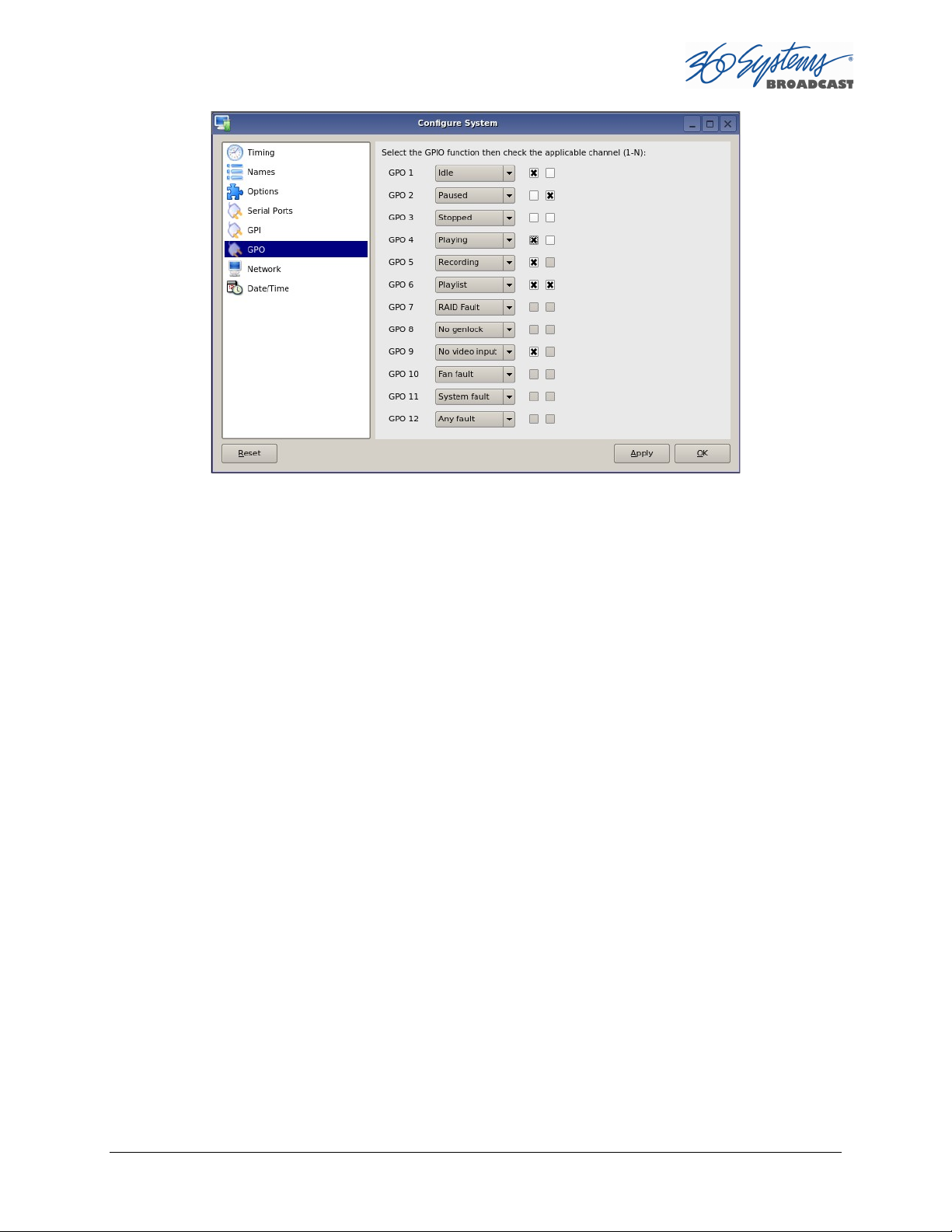
Figure 24 - GPO Configuration Screen
B. Check the EDIT checkbox in the Playlist View of the transport.
C. Place the cursor over a Clip in a Playlist. Right click on the clip. Select EDIT GPO. The
Event Editor (Error! Reference source not found. ) appears:
D. Enable the GPO of interest by checking the corresponding ENABLED checkbox.
E. Enter an offset into the Clip to activate the GPO line in the Offset Field. The form of
the field is Hours, Minutes, Seconds and frames. ( HH:MM:SS:FF )
F. Enter the Duration for the GPO to remain active in the Duration Field using the
same format. Click APPLY to activate the changes.
TSS MINI Operations Manual Page 75
Page 76

Figure 25 – GPO Editor
Mapping GPIO Inputs to Control a Playlist
Playlists can be controlled with the twelve GPI Inputs. See Programming GPI Inputs on page 53.
Page 76 TSS MINI Operations Manual
Page 77

Advanced Topics
System Timing
The TSS MINI Multi Format Video Server is equipped for use with an external genlock signal
as a timing reference. This causes all outputs to be synchronous with other video signals in a
facility.
Adjustment of Genlock Timing will fine tune this synchronization to compensate for
differences in equipment and wiring. This global setting for all outputs allows timing to be
varied by one line of video. The Vertical (lines) setting rarely needs to be adjusted. If required, it
would be adjusted so that the output of the first line of video happens concurrently with other
contributing inputs. The visible effect is that the picture will rise or fall by one line when viewed
at the output of a timed video switcher, or on a genlocked monitor. Note that this setting might
cause SD VBI data such as closed captions (and less likely, HD VANC data2) to appear on
different and possibly inappropriate lines.
2
VANC data carries its line number within the digital data, as such it is less susceptible to issues that arise
from changes in line timing. VBI relies on its actual position in the raster to be associated with a particular
line.
TSS MINI Operations Manual Page 77
Page 78

Figure 26 - Video Timing Adjustment
The Horizontal (nsec) adjustment is used to set the precise timing of the start of the frame
relative to the reference signal, in order to match with other contributing signals. The effect is
not normally visible; extreme settings may result in a slight visible shift of the picture from left to
right.
Page 78 TSS MINI Operations Manual
Page 79

Using Embedded Audio
The TSS MINI Multi Format Video Server provides up to 16-channels of embedded audio. (Note
that not all file formats support 16 channel audio.)
Features include:
Video synchronous 24-bit audio at a 48K sample rate. (Other sampling rates are not
supported.)
The server records and plays Group 1, 2, 3 and 4 audio, (channels 1-16).
In E-E or Input Monitor mode, all embedded audio channels will pass through the server
unaltered, regardless of whether they are being recorded in the selected file format.
User bits in the HD-SDI embedded audio stream are not supported.
Dolby®-E is supported with 360 Systems’ Bit-for-Bit® technology. Note that this requires
using a recording format such as AVC-100 that uses PCM audio recording.
TSS MINI Operations Manual Page 79
Page 80

Ganging Channels for Synchronized Playback
Two video channels can be ganged together for frame-accurate playback. This may be used
for key and fill material (either stills or clips), or multi-channel playout of presentations, such
as synchronized matte backdrops on News Broadcasts, or multi-screen projection.
The channels can be ganged in the following combinations:
Channel 1 can control Channel 2.
Only channel one can be set as the master channel.
To configure Channel Ganging Click EDIT >CONFIGURE >TIMING from the Main Menu. The
video timing adjustment screen of Figure 26 displayed.
To gang Channel 2 to channel 1, set CHANNEL GANGING MASTER to 1 and click the
GANG checkbox on channel 2.
FTP File Transfers
The TSS MINI Server connects over Gigabit Ethernet using its own internal RFC-1359 compliant
FTP server. File transfers to and from the server are managed from an FTP client file transfer
program running on an external system on the network (such as a Windows® or Macintosh®
computer). This provides a rapid way to execute file transfers, allows managing many servers at
once, and does not tie up the server GUI which may already be in use. Error! Reference source
not found.
FTP Client Platform
Flash FXP WINDOWS
DOS FTP WINDOWS
WS FTP WINDOWS XP
Internet Explorer WINDOWS XP
Filezilla WINDOWS MACINTOSH LINUX
Fetch MACINTOSH
CyberDuck MACINTOSH
Table 2 - Supported FTP Clients
FTP programs may also be used to move recorded or edited material between a server and
Network Attached Storage (NAS).
From a networking or system-integration viewpoint, the server appears as a normal FTP
server in any size network, with the exception that it may only receive video, graphic and
scheduling related files that are compatible with the server.
Page 80 TSS MINI Operations Manual
Page 81

The server is designed to be used in a private dedicated video network. A firewall
with VPN capability must be used in systems that require internal security or
connection to public networks.
Consult with a network security specialist for guidance on the best hardware,
programming and practices for your facility’s requirements.
Gigabit Ethernet Cable Quality
The high data rates generated by Gigabit Ethernet require high-quality cable designed for
this application. Low-quality network cables can result in high error rates and lower
transmission speed. For Gigabit operation, standard CAT-5 cable should be used only for
very short cable runs.
New Category 5e (enhanced) cables ensure maximum transfer rates, and should be used as
the minimum standard. Category 6 cable is a good choice for applications where longer
cable runs are required.
Configuring the FTP Interface
Before logging in to the server’s FTP server, the network must be configured according to
the local network topology. This is primarily a matter of setting a static IP address or
configuring
the server to use DHCP to obtain an IP address from a DHCP server. Refer to page Error!
Bookmark not defined. for details on configuring the network settings.
When connecting directly to a PC or Laptop, configure the server as IP address 192.168.1.3,
netmask 255.255.255.0 and disable DHCP. In the PC, double click on the Local Area
Connection Icon in the system tray or in the Network and Dial-Up Connections in the
Control Panel. In the Local Area Connection Status dialog, click on Properties. Click on the
item “Internet Protocol (TCP/IP)” and click on Properties again. In Local Area Connection
Properties, turn off “Obtain an IP Address Automatically“ by selecting “Use the Following IP
Address” and set the address to 192.168.1.2, netmask to 255.255.255.0.
No hardware settings are available or needed. The NET-1 port automatically negotiates port
speed and configures transmit and receive connections, and does not need a “crossover”
cable when connecting directly to a PC.
The actual transfer rate depends on the format of the files being transferred, and the
number of video streams being played or recorded.
Setting the server FTP User and FTP Password
Click on Edit>Configure>Network from the Main GUI Window
Enter the desired FTP User name in the FTP User field
Enter the desired FTP Password in the FTP Password field
Click Apply
TSS MINI Operations Manual Page 81
Page 82

Figure 27 – FTP User and Password Configuration
Logging in to the server FTP Service
Using one of the FTP clients shown in Error! Reference source not found.:
Enter the username and password
When the FTP client is connected, it will display the Clips in the main directory and all of the
sub-folders. Clips can be uploaded, downloaded, deleted and renamed using standard FTP
client commands. Clips in the subfolders can be displayed by entering those folders.
Consult the documentation for your FTP client for information on changing folders.
FTP Transfer Rates
Transfer rate (transfer time relative to clip length) depends greatly on the current operational
demands on the server. This includes the number of channels that are being used, whether
there is recording taking place, the bitrate of the video, and the number of VANC data lines
in use.
Secondarily, the network itself and the source of FTP data can be limiting factors in some
cases. The following rates assume a dedicated network with limited additional traffic, a high
bandwidth FTP source, and a video bit rate of 75 Mb/s with 1 VANC line.
Page 82 TSS MINI Operations Manual
Page 83

Transfer Time for 1 minute of video
Workload
Upload to
TSS MINI
IDLE
14 seconds (45.0 MB/s or 360 Mb/s)
28 seconds (22.5 MB/s or 180 Mb/s)
1 Channel Playing
14 seconds (45.0 MB/s or 360 Mb/s)
28 seconds (22.5 MB/s or 180 Mb/s)
2 Channels Playing
15 seconds (39.4 MB/s or 315.2 Mb/s)
45 seconds (14.0 MB/s or 112 Mb/s)
1
Record, 1
Play 17 seconds (37.0 MB/s or 296 Mb/s)
44 seconds (14.3 MB/s or 114.4 Mb/s)
Download from TSS MINI
Multiple Simultaneous FTP Operations
FTP client programs that allow multiple simultaneous data transfers should be set to allow
only one data connection at a time.
While it is possible to log in from multiple clients, it is only acceptable to perform multiple
file transfers when the system is idle or playing or recording on a single channel.
Overwriting Files
It is the responsibility of the client application (Windows Explorer, FlashFXP, etc) to ask the
user if they want to overwrite a file.
Interrupted and Resumed Transfers
If a transfer is interrupted (for example, by a dropped connection) the transfer must be
restarted. Resumption of a partial transfer is not possible.
Transfer of Edited Segments
Edited segments made on the TSS MINI Server are not available for transfer via FTP.
Supported File Types
The system recognizes media file types by their file extension. It is important that the file
extension properly identifies the file content. Attempts to send a file in one format but
masquerading as another due to a wrong file extension may result in undefined behavior.
It is also true that file extensions such as .mxf and .mov can contain many different formats
of video and audio. The TSS MINI Server will only accept files that contain compatible
formats as defined below.
Always test file import before depending on it for broadcast. Some formats allow wide
variation in the structure of files, and the parameters used in the video compression. The
system will not accept all possible variations, and it is even possible that a file that is
accepted may not operate perfectly in all respects. Always test files from new sources before
going on air.
The TSS MINI Server supports many different codec, container format, resolution and
frame/field rate combinations. While it is not possible to list all possible combinations, the
formats below supported and are known to work.
TSS MINI Operations Manual Page 83
Page 84

1920 X 1080i @ 29.97 or 25 fps
1920 X 1080p @ 59.94 or 50 fps
1280 X 720p @ 59.94 or 50 fps
720 X 512 NTSC @ 29.97 fps
720 X 486 NTSC @ 29.97 fps
720 X 480 NTSC @ 29.97 fps
640 X 480 NTSC @ 29.97 fps
720 X 576 PAL @ 25 fps
720 X 608 PAL @ 25 fps
Page 84 TSS MINI Operations Manual
Page 85

The following codecs and file formats are supported:
H.264/MPEG-4 AVC in .mp4
H.264 or MPEG-4 Part 10, Advanced Video Coding (MPEG-4 AVC) in the .mp4 container is
supported.
H.264/MPEG-4 AVC in .mov
H.264 or MPEG-4 Part 10, Advanced Video Coding (MPEG-4 AVC) in the .mov container is
supported.
AVC Intra 100 in .mxf
AVC Intra-100 using the H.264/MPEG-4 AVC standard in the .mxf container is supported.
MPEG2 PS in .mpg
MPEG-2 (H.222/H.262) Program Stream with a .mpg file extension is supported.
IMX (SMPTE D10) in .mxf
MPEG IMX using H.262/MPEG-2 Part 2 encoding in a .mxf container is supported.
Playlists (.lst, .txt)
A server playlist is a text-based file residing in the ‘lists’ directory. Playlists can be created
off-line and transferred to the server using FTP. See page 132 for further information on
playlist file editing and management.
As-Run Logs (.arl)
As-Run logs are available as a document of content actually played. They may be extracted
through FTP transfer. See page Error! Bookmark not defined. for further information on
using As-Run logs.
TSS MINI Operations Manual Page 85
Page 86

Network Time Protocol
Automatic Date/Time Updates
When using server play-lists in broadcast applications, an accurate record is often needed of
what was played and when. The server’s As-Run logging feature creates such a record, time
stamping each played clip using the machine’s internal date/time clock. Very accurate time
stamping can be achieved by synchronizing the server’s clock to an external time base that is
referenced to Coordinated Universal Time (UTC).
This is accomplished using the Network Time Protocol (NTP) to interrogate time servers
through a network connection. A time server could be an in-house computer or dedicated
time server that is equipped with a GPS receiver, or a radio receiver locked to signals from
the NIST radio station WWV. Alternatively, public time servers may be used which are
accessible through an Internet connection.
Connecting to the Internet
To obtain automatic date/time updates from the public time servers on the Internet, you will
need to provide the server with Internet access. Generally, servers would be connected on a
secure high-speed local area network, with any Internet connection going through a router
with an integrated firewall. The Network Time Protocol uses TCP/IP port number 123, so be
sure the firewall is configured to allow access to this port per Figure 28.
Figure 28 - NTP Network Block Diagram
Page 86 TSS MINI Operations Manual
Page 87

Configuring NTP
The server GUI is used to set the time zone and to enter the networking parameters. The
local GUI must be used, as these configuration screens are not available on the Remote
Workstation Interface.
Selecting the Time Zone
Starting at the main menu bar, Click Edit >Configure >Date-Time screen. When
“Automatic Updates” is not checked, the Region and Zone lists are enabled. Select your
region and then the zone within that region. There may be more than one way to your zone;
America/New York, for example, is the same as US/Eastern. Click the APPLY button to
activate the settings,
After changing the time zone a Quick Restart must be performed before changes become
effective.
Figure 29 - Date/Time Configuration Screen
When Automatic updates is checked, all functions on this page are locked out as they are
automatically adjusted by the NTP service. The NTP Status will be updated when the NTP
service checks the time, displaying the current Offset and Frequency adjustments to the
clock.
TSS MINI Operations Manual Page 87
Page 88
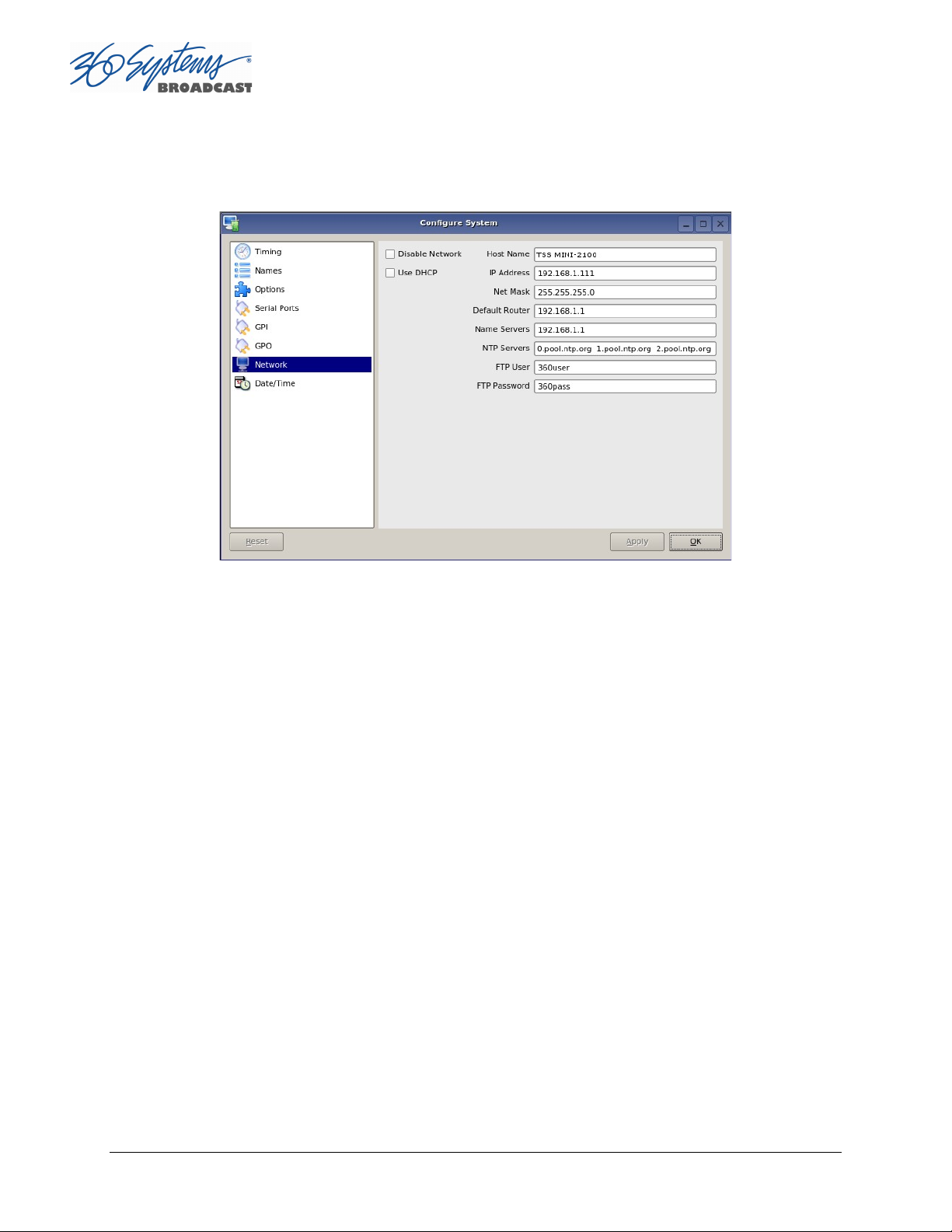
Entering Network Parameters
From the GUI’s main menu bar, click EDIT>CONFIGURE>NETWORK. The following screen
appears. Make sure the basic network parameters have been entered.
Figure 30 - Network Configuration Screen
Disable Network: uncheck
Host Name: (Any name will suffice, but since this name appears on each line of the server’s
diagnostic logs, it is a good idea to keep this short.) The name should also be unique from other
devices on the network.
If “Use DHCP” if not checked, then enter a fixed IP address compatible with your local subnet.
For example,
IP Address: 192.168.1.20
Net Mask: 255.255.255.0
Default Router: 192.168.1.1
The Name Servers and NTP Servers fields provide the information needed to reach the public
time servers. The NTP Servers field contains a list of time servers, either by numeric IP address,
or by site name (URL). Entries are separated by spaces.
The nonprofit Internet Systems Consortium, Inc. (ISC) maintains sites that automatically
return lists of public time servers to an NTP client such as the server. Hence, the NTP Servers
field is initially filled in with the URL’s for these sites (0.pool.ntp.org, for example). Of course
you can overwrite this list with the addresses of specific time servers you may want to use.
However, if you try to clear the NTP Servers field it will be reset to the default list.
Page 88 TSS MINI Operations Manual
Page 89

Note: When URLs (non-numeric site addresses such as pool.ntp.org) are used in the NTP
Servers field, the IP address of at least one DNS (Domain Name server) must be provided in the
Name Servers field. Typically, this address is supplied by your Internet Service Provider.
These name servers translate URL names into numeric IP addresses needed to access the
sites in question.
When using a GPS-based time server which is connected directly to a local area network,
enter its numeric IP address (such as 192.168.1.60) into the NTP Servers field, leaving the
Name Servers field blank.
Also, if you know the numeric IP addresses of the public or corporate time servers on the
Internet, you can enter these addresses, separated by spaces, in the NTP Servers field,
leaving the Name Servers field blank, since there would be no URLs to be resolved.
Note: Not all Network Time servers allow unlimited public access. Refer to www.ntp.org for
more information.
Click the APPLY button to save your changes.
TSS MINI Operations Manual Page 89
Page 90

Automation Control
The optional CXP-5 Auxiliary Interface Module’s serial control inputs connect with many
broadcast automation systems, instant replay panels, video switchers, and remote control
devices.
For compatibility with simple controllers and push buttons, the server also provides 12 GPI
(contact closure) inputs, and 12 programmable command outputs.
Remote Serial Control
The server’s four 9-pin RS-422 serial control inputs permit control of their associated video
channels. The following serial protocols are accepted:
VDCP
BVW
ODETICS Extensions to the BVW protocol
Figure 31 - CXP-5 Detail of Serial Port Connectors
CH1 - Channel 1, also referred to as COM1
CH2 - Channel 2, also referred to as COM2
CH3 - Channel 3, also referred to as COM3 (Not used on TSS MINI)
CH4 - Channel 4, also referred to as COM4 (Not used on TSS MINI)
With VDCP, each port can also respond to channel ID numbers that are equal to, or
multiples of, its base number. For example, channel 1 will also respond to 5, 9, 13, etc. This can
be helpful when an automation system needs to control a number of servers at once
The server’s multiple serial ports allow simultaneous connection of an automation controller
and a desktop editing controller. For example, one could attach an edit controller to Channel 1
for record, playout, and editing; while an automation controller on Channel 3 manages play-toair operations. Alternatively, a single controller could control the operation of all server
channels. A single VDCP controller will commonly control multiple server channels.
It is possible for a single VDCP controller to control multiple server channels through one
physical serial port. This is up to the design of the controller; it cannot be configured in the
server if the controller does not support it. When using a single port to control more than one
Page 90 TSS MINI Operations Manual
Page 91

channel, be sure the Assigned Serial Ports option is unchecked. Do not attempt to use a
different serial port to control one of the video channels that is under multichannel control.
Controller Priority
Only one serial controller can control a given video channel at a time. In general, the first
controller to gain control of a video channel will have exclusive command. This prevents
conflicting instructions that would cause unexpected behavior. The only exception is that the
graphic user interface can immediately take control of a channel by deselecting Serial Control
in that channel’s dialog window.
External controllers are prohibited from taking control away from the GUI. The Serial
Control box must be checked in the channel dialog window before a remote control device can
communicate with that channel.
Configuring the Automation Interface
Setting the automation protocol for a video channel
Each video channel can be configured independently for VDCP or BVW protocol.
To map a protocol to a channel, Click EDIT >CONFIGURE >SERIAL PORTS from the main
pull-down menu. The screen of in Figure 32 is displayed. Use the PORT pulldown to select
COM1, 2, or 3; these map to Video channels 1, 2, or 3.
Select VDCP to map the port to VDCP protocol
Select BVW to map the port to BVW and ODETICS protocols
Note that the ODETICS protocol is layered with the BVW protocol, and that it supports clip
names of up to eight characters only. Clips with longer names will not be displayed by an
Odetics controller and will not be accessible. This includes the demo clips shipped with the
server; see the section on page Error! Bookmark not defined. to rename the clips to allow their
use for testing.
VDCP operation can allow control of a channel by ID number from a different numbered
serial port, while BVW and Odetics protocol control only the channel number corresponding to
the number of the serial port in use. When using both protocols, take care to not allow a VDCP
controller to address a channel that is controlled by BVW/Odetics on another serial port.
If necessary turn on “Assigned Serial Ports” in VDCP Options – this will force VDCP to
control the channel corresponding to the serial port it is connected to regardless of the channel
ID in the control messages. This allows flexible assignment in control systems that limit choices
of channel IDs, and also (with some systems) can reduce the possibility that, if the server is
disconnected for any reason, the controller might have to be reset to resume communication.
TSS MINI Operations Manual Page 91
Page 92

Figure 32 - Serial Port Configuration Screen
Setting the Automation Source Directory
By default, automation equipment will access the Home or Root directory as a source of
clips. The directory accessed by automation equipment can be set for each port as follows.
Select the port to be used (COM1 or COM2).
Click on the FOLDER icon in the PATH field of the Serial Port Configuration Screen.
Navigate to the folder to be accessed by automation equipment.
It is recommended that for most applications only the root directory be used, and the
automation system be relied on for file management rather than the server. Automation can
only see the clips that are in the assigned Automation Source Directory. There are two
classes of applications for folders in conjunction with serial control:
Limiting the number of clips accessible to automation or remote controllers.
Some controllers have limited capacity for clip display and selection. Using a folder to
present only the currently needed clips can streamline operation.
Content can be prevented from being aired but still be readily accessible. Content can
be ingested at any time and made available to air by moving it into the Automation
Source Directory.
“Archived” material can be held in organized folders, then copied into the Automation
Source Directory as needed to air. The copies can then be deleted after airing without
affecting the archived copy.
Page 92 TSS MINI Operations Manual
Page 93

Content for different purposes can be grouped in folders, and selected by changing the
Automation Source Directory.
Segregating material for different broadcast channels
Content can be placed in a folder for each channel, and played out by separate
automation systems or controllers. Each channel can run completely independently –
there can be duplicate file names with different content, and the opportunity for airing
content on the wrong channel is greatly reduced.
Content that is common to both channels can be copied into both directories. When this
is done in the GUI (as opposed to FTP transfer) the copies reference the same data so
they are available immediately and take no additional disk space.
Other Automation Options
As illustrated in Figure 32, a number of check boxes are provided that control how the
server will respond to certain VDCP commands. Once set, these options remain selected
when the server is turned off, and until changed by the user.
NOTE: The following options will apply to both video channels. They cannot be individually
configured for each video channel. Except where noted, they apply only to VDCP operation.
Cue Shows 1st Frame
Upon receiving a Cue With Data or a Play Cue command, the server will cue the clip then jog
to and display the first frame of video. (This also applies to Odetics protocol.)
Cue with Offset (vs. Timestamp)
When checked, the time code for the clip becomes “zero-based” with reference to the head
point. To move to the head point of the clip, the automation controller would send a time
code value of 00:00:00:00, regardless of the clip’s original time stamp. When unchecked, the
server will calculate time code position based upon the time stamp from the first frame of
the unedited clip. Note that this only affects the operation of the serial port, it does not
change the way the server displays time code in the GUI.
Variplay 1X Equals Play
The server will interpret a Variplay 1x command as a Play command. (This also applies to
Odetics protocol.)
Variplay 0 Equals Pause
The server will interpret a Variplay 0x command as a Pause command. (This also applies to
Odetics protocol.)
Report Play (vs Still) At End
When the end of a clip is reached, the server will report Play to the automation controller,
instead of Still.
TSS MINI Operations Manual Page 93
Page 94

Ignore Preroll Commands
A minimum 4-frame pre-roll is required to allow the server time to respond to serial
commands. See the documentation for your controller or automation to find out how to set
the preroll value. Due to various ways preroll commands are implemented in different
systems, it may be sufficient to check only this box. A setting of 4 frames in the automation
controller will then work correctly.
This option is very seldom used; it allows preroll commands to be ignored and assumes that
the operational preroll is 4 frames. Do not check this unless you experience problems with
frame accuracy on recordings and playback transitions. Start with a setting of 4 frames on
the automation system and adjust until you achieve proper timing.
Auto E-E
Toggles Auto E-E mode (input monitor) on/off.
Assigned Serial Ports
VDCP protocol provides for altering the mapping of Serial Port to Video Channel via control
commands. Checking this option will lock the Serial Port to Video Channel ordering.
When checked, any command received on a particular serial port will be used to control
the like numbered video channel. This means that automation systems that use fixed or
limited VDCP ID numbers can use any output to control any channel of the server.
With this option checked, there is no requirement for a Port Open command to allow the
automation to control the channel. With some systems, this can negate the requirement
to restart the automation system when bringing the server online.
Do not check this option when using controllers that communicate with multiple
channels over a single serial port.
Do not use this option with DNF Controls products.
Communication Port Parameters
The serial data transfer parameters for the server are fixed and cannot be changed. These
characteristics are common to all automation controllers:
Baud Rate 38.4 K Baud
Start Bits 1
Data Bits 8
Parity Odd
Stop Bits 1
Page 94 TSS MINI Operations Manual
Page 95

Tested Automation Controllers
VDCP
VDCP
VDCP
VDCP
VDCP
The server has been tested by 360 Systems and the manufacturers of equipment listed
below, and found to operate correctly. This list is not comprehensive, and the inclusion or
absence of a product does not indicate a preference for any make or model. Operational
variations do exist between makes and models.
Manufacturer Controller Protocol Notes
HARRIS AUTOMATION ADC-100 VDCP ALL HARRIS CONTROLLERS SAME
SUNDANCE FAST BREAK VDCP
NVERZION EMC-NT VDCP
CRISPIN CORP. SYSTEM 2000 VDCP
FLORICAL AIR BOSS VDCP
VCI SOLUTIONS (DTG) AIRO VDCP
HARDATA HDX VIDEO ODETICS
IBIS ITA
PEBBLE BEACH SYSTEMS ANEMONE
PROBEL MORPHEUS
PHAROS PLAYTIME
AVECO ASTRA
Tested Remote Control Panels and Switchers
360 Systems servers have been tested by 360 Systems as well as manufacturers of remote
control devices and video switchers listed below, and found to operate correctly.
Manufacturer Controller Protocol Notes
ROSS VIDEO SYNERGY® SWITCHERS VDCP
ECHOLAB OPERA SWITCHERS VDCP
DNF CONTROLS
DNF CONTROLS 300-SSM P2 BVW-75, ALSO ODETICS PROTOCOL
DNF CONTROLS D-MAT VDCP ALSO ODETICS WITH D-MAT-O
ASH VALE SM-2 P2 SLOW MOTION CONTROLLER
BUF VTC-4000 P2 BVW-75, ALSO ODETICS PROTOCOL
BUF SPOT VDCP ALSO ODETICS PROTOCOL
LANCE DESIGNS TDC-100 ODETICS USE INT MODE
HI-TECH SYSTEMS ACTIV CART BOX VDCP ALL VDCP PRODUCTS SAME
4000-CL VDCP ALSO USED WITH DNF SHOT BOX
Uncheck “Assigned Serial Ports” in Serial Port Options when using any DNF Controls product.
TSS MINI Operations Manual Page 95
Page 96

Remote Workstation Interface
The Remote Workstation Interface is a software application that provides control of the
server from PC workstations located within a facility. A remote workstation can access one or
more video channels of the server to perform ingest, playback, trimming, playlisting, traffic
operations or monitoring of server activities.
Applications include—
Control of a server located in a machine room
Ingest station for loading commercials and other content from tape
Edit station for trimming content
Building, editing and running playlists
Remote control of a server located at a transmitter site (“evergreen” backup)
Access to file content and operations by engineering or management
Control of more than one server from a single workstation
On a wireless network, a server can be controlled by a secure
Wi-Fi enabled laptop computer
Remote control in a conference room, or during auditorium presentations
Servers may be securely controlled from a remote location, even across public Internet
connections, with inexpensive VPN (Virtual Private Network) technology.
A single server may be controlled from more than one different location on the network. See
Figure 33.
Similarly, a single computer can run multiple Remote Workstations to control multiple
servers.
Remote Workstation software provides the same functionality as the local GUI with the
following exceptions: It cannot access the server’s network configuration screen, shutdown
the server, access the RAID status display, or display the server’s time-of-day clock.
As of this writing, the current version of Remote Workstation is 3.05.22; this is required to
work with server software version 1.08.561.
Page 96 TSS MINI Operations Manual
Page 97

System Requirements
PC with Windows XP, Vista or Windows 7 installed. Other operating systems have not been
tested and may not be supported.
10 MB free space on the computer hard disk, plus 128 MB RAM.
Figure 33 - Remote Workstation Deployments
About the Remote Workstation Interface
The Remote Workstation Interface consists of a CD-ROM or USB flash drive carrying the
Remote Workstation application for Windows XP, Vista or Windows 7 computers. It selfinstalls using the normal Windows prompts. It is possible to install the Remote Workstation
software on a number of PCs; any of them can then control one or more channels of one or
more servers. Simultaneous active RWI connections to a particular server should be limited
to three.
Operations
Up to four Remote Workstations can simultaneously view the channel activity of a single
server. Only one Remote Workstation at a time can take control of a particular video
channel. Control of the server video channel is not automatically granted to a Remote
Workstation just by attempting to use the GUI; control must be actively taken, using the
TAKE CONTROL option described below. This allows remote monitoring of server channel
activity while greatly reducing the likelihood that a remote user will interfere with operations
initiated by another. All Workstations, including the server’s local GUI, have equal priority
and any can take control of a video channel at any time. Control is granted for server
channels individually, and not automatically for all four; therefore, four Remote Workstations
can each control a separate video channel. Each Remote Workstation can display or close
transport windows without affecting other Workstations or the Local GUI.
TSS MINI Operations Manual Page 97
Page 98

The IP address of a Remote Workstation currently controlling a channel appears in the status
bar on the bottom-left of the Playlist or Channel window.
A menu labeled Options appears at the upper-left of each server channel window. Clicking
this menu presents a drop-down menu with a TAKE CONTROL option. Select this then click
Yes in the confirmation dialog to give control of the video channel to your workstation.
Page 98 TSS MINI Operations Manual
Page 99

Installation
To install Remote Workstation software from CD-ROM or USB drive, insert the media into the
PC.
The auto-run capability of Windows will start the Remote Workstation setup program. If it
does not, select the Run… option of the taskbar Start Menu and type: D:\setup.exe. If
necessary, replace D:\ with the drive letter of the flash drive.
You will be prompted to enter the IP address of the server you wish to control. If you know
the address, enter it here. This information can also be entered after installation.
Read the terms under which this software is licensed to you. If you agree, installation will
continue. If you do not agree, installation will stop. Follow the prompts to finish installation.
By default, the Remote Workstation software installs all required files into the
“C:\Program Files\ Image Server RWI” folder. However, during the installation process an
alternate directory may be specified. If a previous version of Remote Workstation is already
installed on the Host computer, use this feature to install the new version in a uniquely
named folder, for example C:\Program Files\MAXX2420-SHD.
After Installation
A 360 Systems Remote Workstation icon will appear on your desktop. Double click the icon
to open a remote session on the server.
TSS MINI Operations Manual Page 99
Page 100

Figure 34 – Remote Workstation Properties Page
Because multiple simultaneous sessions of Remote Workstation may be run on a single PC, it
is possible to make copies of the Remote Workstation icon and change the IP address of
each, to permit access to any number of servers. Simply right click on the Remote
Workstation icon and select Copy from the pop-up menu. Next, right click anywhere on the
desktop and select Paste. Finally, follow the instructions above to edit the IP address to
match the second server.
Page 100 TSS MINI Operations Manual
 Loading...