


Operations Manual
Model 2470-HD Time Delay

Operations Manual
Model 2470-HD Time Delay
Version 1.04.526
October 2009
Copyright© 2009, 360 Systems
All rights reserved
Printed in the United States of America
100-145-0020 MAXX-2470 HD Time Delay UM

Table of Contents
Safety Notices .................................................................................................... |
4 |
Safety Terms and Symbols .......................................................................... |
4 |
General Safety Caution............................................................................... |
4 |
Personal Injury Precautions ........................................................................ |
4 |
Product Damage Precautions...................................................................... |
5 |
Product Registration ................................................................................... |
5 |
Product Improvements and Upgrades ......................................................... |
5 |
Trademarks and Software Copyrights .......................................................... |
5 |
Introduction....................................................................................................... |
6 |
Time Delay Features .......................................................................................... |
7 |
Installation......................................................................................................... |
8 |
Unpacking................................................................................................. |
8 |
Rack Mounting........................................................................................... |
8 |
System Cooling .......................................................................................... |
9 |
Power Conditioning ................................................................................... |
9 |
About Time Delay Software...................................................................... |
11 |
Front Panel Features ........................................................................................ |
12 |
Reset button............................................................................................. |
12 |
Indicators................................................................................................. |
12 |
Rear Panel Drawing ......................................................................................... |
13 |
Rear Panel Connectors..................................................................................... |
14 |
Operations....................................................................................................... |
15 |
The Graphical User Interface .................................................................... |
15 |
Run/Stop Control ..................................................................................... |
16 |
Time Delay Setting................................................................................... |
16 |
Configure Options Dialog ........................................................................ |
17 |
Configure Network .................................................................................. |
20 |
Date and Time ......................................................................................... |
22 |
Network Time Protocol ............................................................................ |
22 |
Technical Specifications................................................................................... |
26 |
Connector Pin Designations............................................................................. |
28 |
Audio XLR-3 Connector Pinout................................................................. |
28 |
Serial Control Connector Pinout ............................................................... |
28 |
BNC Connectors ...................................................................................... |
28 |
GPI Connector ......................................................................................... |
29 |
System Board Ports................................................................................... |
32 |
Mechanical Drawing........................................................................................ |
33 |
Program Updates from USB Memory............................................................... |
34 |
Updating Firmware .................................................................................. |
35 |
Maintenance .................................................................................................... |
37 |
Fault Diagnostics...................................................................................... |
37 |
Front Panel Indicators............................................................................... |
37 |
Gigabit Ethernet Indicators ....................................................................... |
38 |
2 • 2470HD Time Delay

Access to Components ............................................................................. |
38 |
Removing the Front Panel ........................................................................ |
38 |
Removing the Top Cover.......................................................................... |
39 |
General Handling Precautions.................................................................. |
39 |
Installing/Removing I/O Cards .................................................................. |
40 |
Accessing the Main System Board............................................................. |
40 |
Analog Audio Level Calibration................................................................ |
41 |
Managing the RAID Disk Array................................................................. |
42 |
Notices ............................................................................................................ |
52 |
Product Registration ................................................................................. |
52 |
Product Improvements and Upgrades ....................................................... |
52 |
Repair Policy ........................................................................................... |
52 |
Trademarks .............................................................................................. |
52 |
Software .................................................................................................. |
52 |
Regulatory Certificates and Compliance.................................................... |
52 |
Radio Interference Compliance................................................................. |
53 |
End User License Agreement............................................................................ |
54 |
Limited Warranty............................................................................................. |
56 |
Index................................................................................................................ |
57 |
Table of Contents • 3

Safety Notices
Safety Terms and Symbols
The following warning symbols are used in this manual
English |
ATTENTION: refer to owner’s manual for important |
|
information. |
Français |
ATTENTION: veuillez vous référer au mode d’emploi pour |
|
une information importante. |
Italiano |
ATTENZIONE: fate riferimento al manuale per informazioni |
|
importanti. |
Español |
ATENTCION: favor de referir al manual de operacion por |
|
informacion importante. |
|
|
English |
WARNING: electrical shock hazard. |
Français |
AVERTISSEMENT: danger de choc électrique. |
Italiano |
AVVERTIMENTO: pericolo di shock elettrico. |
Español |
ADVERTENSIA: peligro de choque electrico. |
General Safety Caution
Heed the following important cautions regarding the 2470 HD-Time Delay in order to avoid personal injury or equipment damage.
Only qualified personnel should perform installation and service. Refer to appropriate sections of this product manual for instruction. Contact 360 Systems Customer Support for further explanation, or to clarify any uncertainty.
Disconnect the power cord before removing the cover.
Personal Injury Precautions
To avoid electric shock, do not operate this product with cover removed.
To avoid risk of fire, replace the power cord only with same type and rating as specified. Replace damaged power cords immediately.
This product is grounded through the grounding conductor of the power cord. To avoid electric shock, do not remove or modify the contacts on the plug.
Prevent the power cord from being walked on, pinched, or abraded.
To reduce the risk of fire or electric shock, do not expose this unit to rain or moisture.
Remove jewelry, such as rings, watches, or necklaces before servicing this equipment.
4 • 2470HD Time Delay

Product Damage Precautions
The 2470 HD-Time Delay contains hard disk drives and other fragile electronic and mechanical devices. While this product is very reliable, it is still vulnerable to shock. Handle it with care, and exercise caution not to drop or bump the recorder as damage to internal components may result. Turn off power before moving the Time Delay.
Do not obstruct air vents. Maintain an ambient temperature below 30°C (86°F).
Clean only with a soft cloth dampened with water. Do not spray cleaners or solvents directly on the product.
 CAUTION:
Replace battery only with the same, or equivalent, battery type. Follow all local laws regarding the disposal of BR and CR Lithium batteries. Batteries should be fully discharged prior to disposal.
 CAUTION:
Never use the rear-panel power supply switch to shutdown the Time Delay. Doing so may cause errors in the hard disk array. Should this happen, the array can be reinitialized without any data loss; however, the process may take several hours. Shutdown the system only by momentarily pressing the front panel reset button, or through the On-Screen user interface.
Product Registration
Important: As the owner of new capital equipment, you will want to take advantage of product information, enhancements, upgrades, or notifications issued by 360 Systems. Send in your Warranty Card so 360 Systems can remain in contact with you. Mail or fax it to 360 Systems offices in the USA at the address on page 52.
Product Improvements and Upgrades
360 Systems reserves the right to make changes and/or improvements to its products without incurring any obligation to incorporate such changes or improvements in units previously sold. Certain features mentioned in this document may not be present in all models. Time Delays are not offered for sale in all countries.
Trademarks and Software Copyrights
Image Server, MAXX, 360 Systems, 360 Systems Broadcast, Bit-for-Bit, and Direct Digital Import are trademarks or registered trademarks of 360 Systems in the U.S. and/or foreign countries. Other trademarks referred to in this document are the property of their respective owners.
Software in this product is based on the work of, or is copyright by, 360 Systems, SuSE® GmbH, Trolltech, and FreeType Team. Copyright 2003-2009 by 360 Systems.
Safety Notices 5

2470-HD Time Delay
Introduction
360 Systems 2470 HD-Time Delay is a high-quality program delay for television broadcast, satellite delivery, and other applications requiring a user-settable delay time for video, audio, and ancillary data. Applications for the delay include:
•Compensation for time zone differences, where a program is received at a different time than when it needs to air.
•Program origination delays, where content is time-shifted prior to transmission or distribution.
•“+1” channels that allow cablecasters to offer multiple feeds of the same program content to maximize channel exposure with limited additional cost. Viewers can choose to see a variety of different shows in their chosen viewing time, or see an immediate repeat of a show that interested them simply by changing the channel.
The can be thought of as a black box that records video, audio, and specific ancillary data information; it then delays the playback of the program by a user-selectable time period. Whatever goes in, comes out later.
The Time Delay will operate as a set-and-forget box with no user intervention. On restarting after a power failure, it will again start delaying the input according to the most recent user settings. The delay time is user-programmable from 6 seconds to greater than 8 hours. The programmed delay interval is frame-accurate over an indefinite time period; if several Time Delays are fed identical input signals, they will remain in sync indefinitely.
The Time Delay employs high quality, visually lossless JPEG2000 video encoding at 100 Mb/s. JPEG2000 is an ideal codec for this application, providing superior final image quality when used in conjunction with other codec processes such as MPEG or H.264 for satellite transmission and cable distribution.
16 embedded audio channels are provided. Alternately, two +4 dBu analog channels are available. Audio I/O is on chassis-mounted gold-plated XLR-3 connectors. Available options allow for 8 channels of AES/EBU.
ATC Time Code is reproduced, as well as up to 12 selectable lines of Vertical Interval Ancillary (VANC) data. (In 1080i 6 lines from field 1 are selected, and the corresponding lines in field 2 are automatically selected.)
6 • 2470HD Time Delay

Time Delay Features
•Functions in a stand-alone configuration with no external machine controls, and requires no third-party software.
•Operates unattended for long periods of time. No operator intervention or file maintenance required for continuous operation.
•All settings are non-volatile, allowing unattended restart on power-up. The unit automatically reconfigures itself for the last-specified delay time, and re-enters the record/playback cycle.
•System configuration is accomplished through a GUI interface using a local keyboard, mouse and VGA monitor.
•Allows user to specify a frame-accurate delay time, such that multiple units will play back in frame-accurate sync when fed identical input video.
•RAID-5 hardware-based drive array protects stored data against a single drive failure.
•1 HD-SDI program input.
•1 E-E monitor output, 1 delayed program output. HD-SDI and HDMI connectors provided. Each output appears on both HD-SDI and HDMI simultaneously.
•Records video in 10-bit JPEG 2000, at 100 Mb/s for visually lossless picture quality.
•Records user-choice of audio sources: 8 stereo pairs SDI embedded, or 1 stereo pair of +4 analog. XLR-3 connectors are provided on the rear panel. In addition, 4 stereo pairs AES/EBU digital are selectable with the addition of the optional DXP-5.
•Compatible with Dolby® surround encoding.
•Captures and plays ATC (Horizontal ancillary time code).
•Synchronizes to video input.
•Upon loss of input video, records black and uses internal reference until input is restored.
•Outputs black and audio silence during the recording interval preceding the desired program output delay.
•Captures and plays 12 selectable lines of VANC data.
•Front panel status LEDs: genlock, power, fan failure, drives( RAID) , system errors.
•System Monitor signals available from GPI Outputs to indicate RAID status, fan failure, system errors, and loss of input.
•2 rack-unit (3¾”) height. Forced-air cooling.
Introduction & Features 7

Installation
Unpacking
Your 2470HD Time Delay has been carefully inspected and calibrated before shipment to allow immediate operation upon installation. Check all items for signs of visible damage which may have occurred during shipment. If any item is damaged, contact the carrier to file a claim.
Keep the packing materials in the event that the unit must be shipped. If the original packaging is not available, make sure that the following criteria are met:
•Packaging must be able to withstand the product weight.
•Product must be held firmly within the package.
•There must be at least two inches (50mm) of space between the product and outer container.
•The corners of the product must be protected.
Package Contents
Confirm that all items on the packing list have been received. Contact 360 Systems if any item is missing.
Model 2470HD Time Delay
Keyboard
2-Button Wheel Mouse.
Software backup on USB memory stick
Operations Manual
Power cord
Warranty Card
The Time Delay is not shipped with a video monitor. Select a VESA-compliant CRT or LCD monitor capable of a refresh rate of at least 75 Hz. Note that the Time Delay may not start correctly if an unsuitable monitor is connected.
If you own more than one Time Delay, it may be appropriate to use a single keyboard, monitor, and mouse with a KVM switch to select between units. Not all KVM switching systems are compatible. The KVM switch must supply an active signal to the Time Delay at all times, even when switched away from it. When first powering up the Time Delay, use only the supplied keyboard and mouse directly connected. Then test the KVM switch system that will be used thoroughly before installation is completed. NOTE: If the mouse and keyboard connections are interchanged, the Time Delay may not boot up properly. Be especially careful about this when using extender cables.
Rack Mounting
There are four adhesive-backed rubber feet on the Time Delay. These may need to be removed when rack mounting the unit.
Cables attached to the rear of the Time Delay should be supported by the rack mounting rails. Do not support substantial cable weight from the Time Delay.
Remove the front panel to expose the rack screw slots. Fasten the Time Delay into the rack. Replace the front panel. Tighten the front panel access screws.
8 • 2470HD Time Delay

Important Installation Notes
System Cooling
When many pieces of equipment are mounted in an equipment rack, a considerable amount of heat may be produced, which must be removed efficiently. Further, a lower operating temperature will make equipment operate more reliably, and it will last longer. In the extreme case, excessive temperatures cause rapid equipment failure, and damage which can be difficult to repair.
Heat in an equipment rack should be removed by forced air. This is often accomplished by blowers installed in the top of the rack, venting into the room. An alternative is to draw hot air from the top of the rack into an air-conditioning return duct, and not vent it into the equipment room; cold air should be ducted into the bottom of the rack.
The optimum air temperature for cooling electronic equipment is 25° C (72° F). When many pieces of equipment are contributing to the heat load, a substantial air-flow will be needed, and the inlet temperature may need to be lower.
Check These Points
•Are all ventilation holes in the Time Delay free of obstruction?
•Can blowers or HVAC system adequately remove heat from the equipment rack?
•Have you measured the actual temperature inside the rack? Do this near the top.
•Verify that the HVAC system is not on a timer that can shut off on weekends or holidays.
•What procedures are in place to protect the equipment when the HVAC system fails?
Power Conditioning
It is good practice to operate an on-air video Time Delay from an Uninterruptible Power Source, or UPS. All utility power systems experience occasional transient events, including brownouts and dropouts, which are capable of taking the Time Delay off the air. It is the station operator’s job to plan for and overcome such contingencies.
UPS units suitable for smoothing short-term power line problems come in two varieties:
Change-over UPS Design
This design senses drop-outs and low line voltage, and switches its output to an internal inverter operating from a battery. This UPS is low in cost, and is most often used in non-critical applications such as desk-top computers. A disadvantage is that it may create its own power transients when switching between utility power and its inverter supply. For this reason 360 Systems does not recommend this type for use with the Time Delay.
Continuous Conversion UPS Design
This improved design continuously converts utility power to DC, stores it in a battery, then produces isolated AC power from an inverter. It never switches, and is immune to input transients, brownouts, and blackouts. Models are available with batteries of almost any size, making the continuous-conversion UPS suitable for transient suppression or long-term operating power in the absence of utility power.
Introduction & Features 9
Recommended UPS Models
The following makes of continuous conversion UPS systems are suitable for use with 360 Systems’ video products:
APC Smart-UPS 2200-XL
Eaton/Powerware Corporation, Model 9125, www.powerware.com
This unit is available in several different configurations to accommodate various current load and power failure support times.
The minimum requirement for maximum current load for a single Time Delay is 2 amps.
Operating Environment
A Time Delay is a critical element in broadcast operations. Its installation should safeguard it from every external event that can interfere with it doing the task expected of it. 360 Systems’ engineers have experience with thousands of installations, and have become aware of a number of environmental factors that can adversely affect performance. Two of these have already been discussed: power conditioning and inadequate cooling. Two others, less obvious, should also be considered:
RF Interference by Cell Phones
Many people are not aware that cell phones can attain a very substantial power output, even when no conversation is taking place. You may have experienced the effect of a cell phone interfering with a common desk phone placed nearby. Carrying a cell phone into a machine room where it is in close proximity to broadcast equipment and its associated wiring is unwise. They are able to interfere with serial control commands, video synchronization, and in some cases can crash the CPU in equipment.
Some major broadcasters prohibit the carrying of cell phones into certain machine areas. 360 Systems believes that the risk of undesired equipment behavior from their RF fields is very real.
Static Discharge
Static electricity discharge is accepted by most people as an inevitable consequence of living in a dry area. It is, rather, a result of floor coverings that may enhance appearances, but are inappropriate for use around critical pieces of broadcast equipment. Static discharge can do two adverse things:
•Discharge into a connector can—and will—destroy internal circuitry of equipment. The result will always be difficult to diagnose and repair.
•Discharge to equipment frames or wiring can crash a CPU and take the station off the air. The event may seem random or unrelated to static, but it is clearly a catastrophic event—and one that can repeat indefinitely as humidity varies.
10 • 2470HD Time Delay

Several steps can be taken to protect equipment from static discharge:
•Do not install critical broadcast equipment in a room with carpeting.
•Connect equipment racks directly to an earth ground with a heavy copper conductor.
•Do not operate equipment with a lifted safety ground (green frame ground).
•Install a humidifier, if necessary, to reduce the likelihood of static discharge.
About Time Delay Software
The Time Delay is shipped with its application programs and operating system installed.
The first time that it is started, it must be connected to a keyboard, monitor and mouse. The Time Delay will ask you to accept the Software Licensing Agreement before it will operate. This screen will only appear during the initial startup.
If for any reason it becomes necessary to reinstall any software, refer to the Software / Firmware updates chapter on page 374 for instructions.
Introduction & Features 11
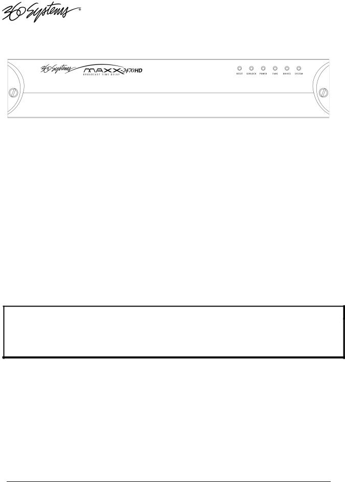
Front Panel Features
Reset button
The recessed Reset button initiates start-up and shut-down of the 2470HD Time Delay. Press it momentarily to start the Time Delay. A sequence of start-up screens will appear, ending with the graphic user interface.
When the Time Delay is running, pressing the Reset button momentarily will cause the system to begin an orderly shutdown. This can also be initiated from the GUI by selecting
START > SHUTDOWN > SHUTDOWN. In most cases the power will shut off automatically, however if the front panel lights begin to blink the file system has been properly closed and it is safe to force the power off by holding the front panel button in for 4 seconds.
In the event that the system has stopped responding to commands and will not shutdown, hold the button in for 4 seconds to force a power down.
Do not use the rear panel switch on the power supply to shut down the Time Delay. Abrupt power loss can cause loss of information stored on the disk array. The rear panel power switch can be used to prevent re-application of power during service procedures once the normal shut down sequence is complete.
CAUTION:
LOSS OF DATA CAN OCCUR IF THE POWER IS TURNED OFF WITHOUT A SHUTDOWN.
USE THE FOUR SECOND SHUTDOWN ONLY IF THE SYSTEM IS NOT RESPONDING OR THE SHUTDOWN PROCESS DOES NOT TURN THE POWER OFF AUTOMATICALLY.
Indicators
Five blue LED Status Indicators appear on the front panel. These indicators are illuminated continuously or are dark when the system is functioning normally. Error conditions are indicated by flashing. See the table Front Panel Indicators on page 37 for diagnostic meanings.
The Status Indicators are also available as GPI outputs, along with an additional output warning for loss of input. See GPI connector on page 29 for details.
12 • 2470HD Time Delay

Rear Panel Drawing
1 |
2 |
3 |
4 |
5 |
6 |
7 |
8 |
|||||
|
|
|
|
|
|
|
|
|
|
|
|
|
|
|
|
|
|
|
|
|
|
|
|
|
|
|
|
9 |
10 |
11 |
12 |
13 |
14 |
15 |
16 |
17 |
18 |
19 |
1. |
Serial control port (EIA-422) (Future use.) |
|
|
|
11. |
Keyboard port |
|
|
||||
2. |
(2) |
XLR-3 audio outputs |
|
|
|
|
12. |
Mouse port |
|
|
||
3. |
(2) |
XLR-3 audio monitors |
|
|
|
|
13. |
SVGA monitor port |
|
|
||
4. |
(2) |
XLR-3 audio inputs |
|
|
|
|
|
14. |
GPI port, 26-pin female |
|
|
|
5. |
Genlock Input (Future Use) |
|
|
|
15. |
Gigabit Ethernet ports (Use NET1 only.) |
|
|||||
6. |
HD-SDI main Program output |
|
|
|
16. |
USB Ports (Use only for program updates) |
|
|||||
7. |
HD-SDI E-E monitor output |
|
|
|
17. |
Audio Expander connector |
|
|
||||
8. |
HD-SDI video input |
|
|
|
|
|
18. |
HDMI main Program output |
|
|
||
9. |
AC Power connector |
|
|
|
|
|
19. |
HDMI E-E monitor output |
|
|
||
10.AC Power switch
Introduction & Features 13

Rear Panel Connectors
The Time Delay provides one video input with up to 16 Embedded audio channels, one delayed video output with audio, and a second monitoring output which reflects input video and audio (E-E).
Additionally, there are two analog audio inputs that can be used instead of embedded audio. These correspond to audio channels 1 and 2, and appear in the embedded audio on the video outputs and the XLR outputs. The XLR audio outputs will also carry audio channels 1 and 2 when embedded audio is selected as the input source.
The HDMI outputs carry audio channels 1 and 2 when either embedded or analog audio is selected. Audio from other channels cannot be output by either Analog or HDMI audio.
REAR PANEL DESIGNATION |
CONNECTOR TYPE |
FUNCTION |
HD-SDI IN |
BNC |
HD-SDI Video Program Input |
HD-SDI MON OUT |
BNC |
HD-SDI E-E monitor out |
MON OUT |
HDMI |
Local E-E monitor |
HD-SDI PGM OUT |
BNC |
Main HD-SDI Video Program Out |
PGM Out |
HDMI |
Local Program output |
|
|
|
ANALOG IN LEFT |
XLR |
Audio Channel 1 Input |
ANALOG IN RIGHT |
XLR |
Audio Channel 2 Input |
ANALOG PGM OUT L |
XLR |
Audio Channel 1 Main Program Out |
ANALOG PGM OUT R |
XLR |
Audio Channel 2 Main Program Out |
ANALOG MON OUT L |
XLR |
Audio Channel 1 E-E Out |
ANALOG MON OUT R |
XLR |
Audio Channel 2 E-E Out |
|
|
|
GPIO |
DB-26 |
Error Monitor outputs |
GENLOCK |
BNC |
Future use |
NET 1 |
RJ-45 |
Gigabit Ethernet (for diagnostic use) |
Serial In |
DB-9 |
future use |
Other Motherboard I/O |
various |
future use |
14 2470HD Time Delay
Operations
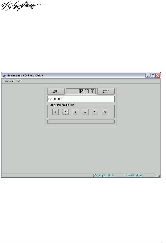
The Graphical User Interface
The Time Delay uses a Graphic User Interface (GUI) to control most functions. A keyboard and mouse are included, and the user needs to supply an SVGA monitor—either CRT or flat-panel.
The GUI is divided into two sections: Run/Stop control, and Time Delay Set. Controls and displays for each section are described below.
In addition, the Menu Bar provides two dialogs, accessed through Configure>Options, and Help>About.
Graphical User Interface
Operations 15

Run, Stop, Time to Air display
Time Delay Setting and Quick Select Presets
Run/Stop Control
Run
The RUN button initiates or restarts the time delay process. Press RUN to begin a new delay cycle, and restart the Time-to-Air countdown. When the countdown reaches zero, it changes to ON LINE, and the delayed video begins playing from the main Program Output.
Upon power up the Time Delay will automatically enter Run mode and start the delay process.
Stop
The STOP button stops playout and clears stored program content from memory. Note that the Time Delay value can only be changed when the machine is in the STOP mode.
Time to Air
Initially, the Time to Air display shows the selected Time Delay Setting. Once RUN is pressed and the recording process sets up and commences, Time to Air is a countdown value, displaying the time remaining before delayed program material reaches the output. It is an approximate display value; it is not directly locked to the video timing.
Time Delay Setting
Delay time is entered and displayed in the DELAY TIME window in HH:MM:SS:FF format. (Hours:Minutes:Seconds:Frames) The desired time is entered from the keyboard from left-to-right.
Delay times may also be entered as whole units of seconds, minutes, hours, by appending a suffix, (s, m, or h) to the value entered into the text box, such as “120m” or “30s.”
Delay Hours Quick Select
Six preset buttons provide a rapid way to set a delay time to an even number of hours from 1 to 6. With the machine stopped, clicking on one of these buttons will immediately load that time value, expressed in hours. An appropriate number of zeros will also be entered for MM:SS:FF. The presets are not active while the machine is running.
16 2470HD Time Delay
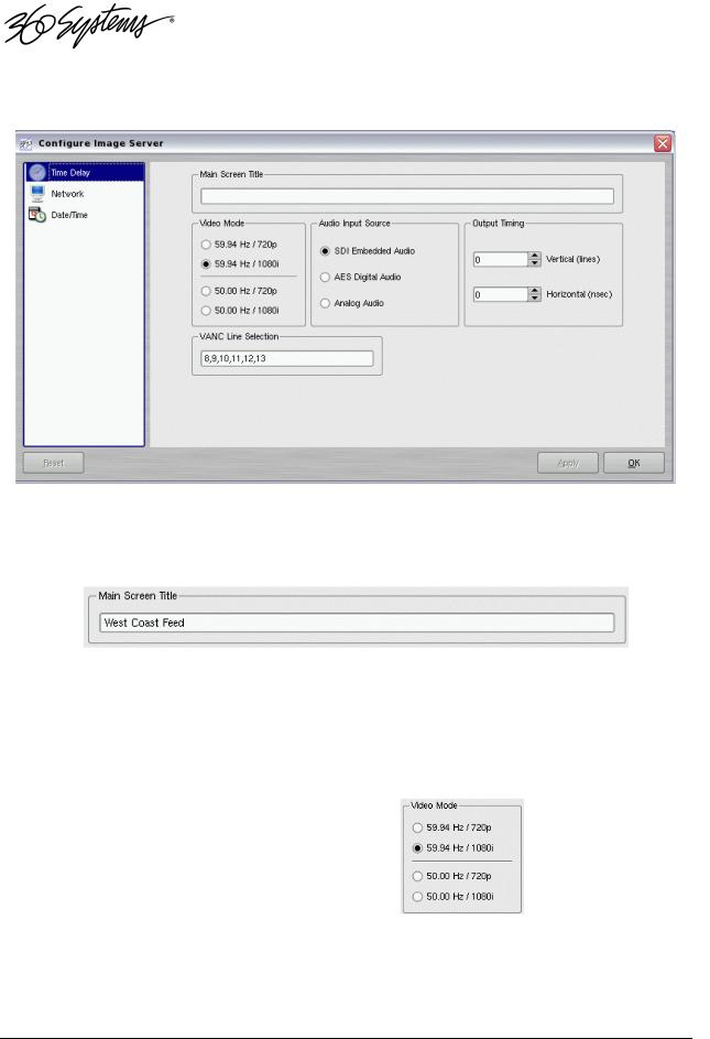
Configure Options Dialog
Configure Options Dialog
Main Screen Title
This allows a user selected title to replace the default “Time Delay” in the title bar of the main GUI window.
Video Mode
Four radio buttons select the Video Mode, which includes the frame rate and video format. These are:
59.94 Hz / 720p
59.94 Hz / 1080i
50 Hz / 720p
50 Hz / 1080i
This setting can only be changed when the Time Delay is stopped. When it is changed, the unit will display a warning and then automatically perform a quick restart to initialize in the newly selected mode.
Operations 17
 Loading...