


O P E R A T I O N Smanual

™
MAXX-1200-HD™ / MAXX-1200-EX™
High Definition Video Servers
Operations Manual
Rev. 1.8 June. 2012
Software version 1.08.561
Copyright © 2012, 360 Systems
All rights reserved
Printed in the United States of America

Page 2 |
MAXX-1200 Owner’s Manual |

™
Contents |
|
Preface _______________________________________________________________ 9 |
|
Software and Operations Manual Revisions.................................. |
9 |
Safety Notices ________________________________________________________ 10 |
|
Safety Terms and Symbols.......................................................... |
10 |
General Safety Caution .............................................................. |
10 |
Personal Injury Precautions ........................................................ |
10 |
Important Safety Instructions ...................................................... |
11 |
Product Damage Precautions ..................................................... |
12 |
Product Registration ................................................................... |
12 |
Product Improvements and Upgrades......................................... |
12 |
Trademarks ................................................................................ |
12 |
Software Copyrights ................................................................... |
12 |
Video/Audio Copyright Reminder .............................................. |
12 |
Introduction _________________________________________________________ 13 |
|
Key Features and Benefits ...................................................................... |
16 |
Applications for 360 Systems Servers ..................................................... |
17 |
Accessory Information ........................................................................... |
18 |
Installation___________________________________________________________ 19 |
|
Unpacking............................................................................................. |
19 |
Package Contents....................................................................... |
19 |
Important Installation Notes ................................................................... |
20 |
System Cooling .......................................................................... |
20 |
Power Conditioning ................................................................... |
20 |
About Server Software ........................................................................... |
22 |
Rack Mounting ...................................................................................... |
22 |
Mounting a DXP-2 Audio Module.............................................. |
22 |
Connecting the Monitor, Mouse and Keyboard .......................... |
22 |
Server Hardware Interface _____________________________________________ 23 |
|
Front Panel Elements ............................................................................. |
23 |
Reset (Power ON/OFF) Button ................................................... |
23 |
Indicators................................................................................... |
23 |
Rear Panel Elements............................................................................... |
25 |
Video Inputs .............................................................................. |
25 |
Video Outputs ........................................................................... |
25 |
Audio I/O................................................................................... |
25 |
Serial Control Ports .................................................................... |
26 |
Gigabit Ethernet Port.................................................................. |
26 |
GPI Control................................................................................ |
26 |
Genlock Sync Reference ............................................................ |
26 |
Keyboard ................................................................................... |
27 |
Mouse........................................................................................ |
27 |
MAXX-1200 Owner’s Manual |
Page 3 |

Monitor...................................................................................... |
27 |
Serial Port .................................................................................. |
27 |
USB Ports................................................................................... |
27 |
AC Power .................................................................................. |
27 |
Basic Operations______________________________________________________ 28
The Server Desktop................................................................................ |
28 |
Launching the Graphic User Interface ........................................ |
28 |
Shutting Down the Server .......................................................... |
28 |
Graphic User Interface Overview........................................................... |
29 |
System Menu Bar ....................................................................... |
30 |
Show Menu ............................................................................... |
30 |
Edit Menu .................................................................................. |
30 |
Windows Menu ......................................................................... |
30 |
Help Menu ................................................................................ |
31 |
The Status Bar ............................................................................ |
31 |
The Transport Channel View...................................................... |
32 |
Transport Menu Bar ................................................................... |
32 |
File Menu .................................................................................. |
32 |
Options Menu............................................................................ |
33 |
Playlist Menu Bar ....................................................................... |
34 |
File Menu .................................................................................. |
34 |
Options Menu............................................................................ |
35 |
Initial System Configuration ................................................................... |
36 |
Selecting a Sync Reference......................................................... |
36 |
Setting the Video Sync Source.................................................... |
36 |
Selecting a Video Format ........................................................... |
37 |
Making a Recording from the GUI ......................................................... |
38 |
Record Configuration Options.................................................... |
38 |
Setting the Video Bit Rate........................................................... |
38 |
Setting the Audio Input Source................................................... |
39 |
Setting an Audio Delay Time...................................................... |
39 |
Audio Rate Conversion .............................................................. |
40 |
Setting VANC Line Selections..................................................... |
41 |
Selecting a Time Code Source.................................................... |
41 |
Beginning Recording.................................................................. |
41 |
Making a Crash Recording ......................................................... |
42 |
Making a Named Recording....................................................... |
42 |
Monitoring a Recording Source with E-E Mode........................... |
43 |
Playing a Clip from the GUI................................................................... |
45 |
Beginning Playback.................................................................... |
45 |
Looping a Clip ........................................................................... |
45 |
Pausing a Clip ............................................................................ |
45 |
Ejecting a Clip............................................................................ |
46 |
Using Jog ................................................................................... |
46 |
Using Go To Frame and the Frame Locator ................................ |
46 |
Using Fast Forward / Rewind...................................................... |
46 |
Slow Motion Playback ............................................................... |
46 |
Using Shuttle to Control Playback Speed.................................... |
47 |
Editing a Clip ......................................................................................... |
48 |
Using Edit While Recording ....................................................... |
48 |
Page 4 |
MAXX-1200 Owner’s Manual |

System Configuration............................................................................. |
50 |
Assigning Names to the Server and Transport Channels.............. |
50 |
Programming GPIO Outputs ...................................................... |
51 |
Programming GPI Inputs ............................................................ |
52 |
Configuring the Network............................................................ |
53 |
Setting the Date and Time .......................................................... |
55 |
Clip Navigator ....................................................................................... |
56 |
Renaming and Deleting Clips..................................................... |
56 |
Sorting Clips .............................................................................. |
56 |
Filtering the Clip Display............................................................ |
56 |
Finding Clips.............................................................................. |
57 |
Finding Clips Using Wildcards ................................................... |
57 |
Finding Clips Using Regular Expressions .................................... |
58 |
Using Playlists ....................................................................................... |
59 |
The Playlist View ....................................................................... |
60 |
Creating and Running a Playlist.................................................. |
61 |
Loading a Playlist (FILE>OPEN) ................................................ |
62 |
Saving a New Playlist (FILE>SAVE AS) ...................................... |
62 |
Saving Existing Playlist (FILE>SAVE).......................................... |
62 |
Setting Playlist Start Time ........................................................... |
62 |
Stopping Playlist (STOP)............................................................. |
63 |
Pausing Playlist (PLAY/PAUSE) ................................................... |
63 |
Cueing a Clip (CUE)................................................................... |
63 |
Looping Playlist (LOOP [X] )...................................................... |
63 |
Show First Frame of CUED Clip (SHOW) ................................... |
63 |
Preparing Next Clip for Playback (NEXT).................................... |
63 |
Jumping To Selected Clip (JUMP)............................................... |
63 |
Automatic Scrolling to Currently Playing Clip (HOME)............... |
64 |
Setting Maximum Played Items to Keep...................................... |
64 |
Enabling As-Run Logging............................................................ |
64 |
Viewing, Editing and Archiving Playlists..................................... |
64 |
Editing Playlists...................................................................................... |
65 |
Removing Clip from Playlist....................................................... |
65 |
Removing All Clips Above or Below the Selected Clip ............... |
65 |
Inserting a HOLD into a Playlist ................................................. |
65 |
Appending a Playlist (FILE >APPEND)....................................... |
65 |
Changing Duration of Clips in a Playlist ..................................... |
66 |
Mapping GPO to Playlist Events................................................. |
66 |
Mapping GPI to Control a Playlist .............................................. |
67 |
Advanced Topics______________________________________________________ 68 |
|
System Timing ........................................................................... |
68 |
Using Embedded Audio ............................................................. |
69 |
Using Audio Sample Rate Conversion ........................................ |
69 |
Ganging Channels for Synchronized Playback ........................... |
70 |
Combined Video and Graphics Capability ................................. |
71 |
Importing TARGA Graphics Files ............................................... |
71 |
Animation Import (Uncompressed .mov files)............................. |
71 |
Still Frames ................................................................................ |
72 |
FTP File Transfers....................................................................... |
73 |
Using MAXX-HD with the Edius NLE _____________________________________ 80 |
|
MAXX-1200 Owner’s Manual |
Page 5 |

Network Time Protocol ________________________________________________ 87
Automatic Date/Time Updates ................................................... |
87 |
Connecting to the Internet.......................................................... |
87 |
Configuring NTP ........................................................................ |
88 |
Selecting the Time Zone............................................................. |
88 |
Entering Network Parameters ..................................................... |
89 |
Automation Control ___________________________________________________ 91
Remote Serial Control ................................................................ |
91 |
Configuring the Automation Interface......................................... |
92 |
Other Automation Options......................................................... |
94 |
Tested Automation Controllers................................................... |
96 |
Tested Remote Control Panels and Switchers ............................. |
96 |
Remote Workstation Interface __________________________________________ 97
System Requirements ................................................................. |
97 |
About the Remote Workstation Interface .................................... |
98 |
Operations................................................................................. |
98 |
Installation ................................................................................. |
99 |
After Installation......................................................................... |
99 |
Hard Disk Management_______________________________________________ 100
About RAID 5 .......................................................................... |
101 |
Improved Write Performance ................................................... |
101 |
Managing Disk Arrays.......................................................................... |
102 |
Error Notification and Repair.................................................... |
102 |
Log-In to the RAID Utilities ...................................................... |
104 |
Determining the Condition of the RAID Array .......................... |
105 |
Displaying the Alarm Log of the Raid Array.............................. |
106 |
Checking Status of the Drives................................................... |
107 |
Removing the Degraded Drive from the RAID Unit.................. |
108 |
Rebuilding the RAID Array....................................................... |
109 |
Replacing Hard Drives ............................................................. |
109 |
RAID Controller Settings .......................................................... |
110 |
Multi-Channel Audio Module __________________________________________ 111
Audio Input/Output Modules ................................................... |
111 |
|
DXP-2 |
Digital Audio Module ................................................... |
111 |
DXP-2 |
Technical Specifications................................................ |
112 |
Maintenance ________________________________________________________ 113
Fault Diagnostics ................................................................................. |
113 |
Front Panel Indicators .............................................................. |
113 |
Gigabit Ethernet Indicators ....................................................... |
114 |
Access to Components......................................................................... |
114 |
Removing the Front Panel ........................................................ |
114 |
Removing the Top Cover ......................................................... |
114 |
General Handling Precautions.................................................. |
115 |
Installing/Removing I/O Cards.................................................. |
115 |
Audio Level Calibration ....................................................................... |
116 |
Calibration Procedure .............................................................. |
116 |
Program Updates from USB Memory ................................................... |
117 |
Page 6 |
MAXX-1200 Owner’s Manual |

Updating Firmware .............................................................................. |
118 |
Replacing a Hard Drive ....................................................................... |
120 |
Factory Repair Policy ........................................................................... |
121 |
Regulatory Certifications ...................................................................... |
121 |
Safety....................................................................................... |
121 |
Radio Interference Compliance ................................................ |
121 |
Product Warranty____________________________________________________ 123
End User License Agreement___________________________________________ 124
For Server Software .................................................................. |
124 |
Appendix A _________________________________________________________ 126
Connector Specifications ..................................................................... |
126 |
Audio XLR-3 Connector Pinout ................................................ |
126 |
Serial Control Connector Pinout............................................... |
126 |
BNC Connectors ...................................................................... |
127 |
GPIO Connector ...................................................................... |
127 |
GPI Connector Pinout .............................................................. |
127 |
System Board Ports .................................................................. |
129 |
Appendix B _________________________________________________________ 130
Serial Command Protocols................................................................... |
130 |
VDCP Command Table............................................................ |
130 |
P2 (BVW) Serial Command Table............................................. |
132 |
Odetics® Protocol .................................................................... |
133 |
Appendix C _________________________________________________________ 136
Technical Specifications....................................................................... |
136 |
Keyboard Shortcuts.............................................................................. |
137 |
Appendix D _________________________________________________________ 138
Playlist Management Detail ................................................................. |
138 |
Appendix E__________________________________________________________ 141
As-Run Logging Detail ......................................................................... |
141 |
As-Run Naming Convention..................................................... |
141 |
Sample As-Run Log .................................................................. |
141 |
As-Run Log Page Header.......................................................... |
142 |
As-Run Log Body ..................................................................... |
142 |
Appendix F__________________________________________________________ 143
Mechanical Drawing............................................................................ |
143 |
Index_______________________________________________________________ 144
MAXX-1200 Owner’s Manual |
Page 7 |

Preface
This manual provides installation, setup and operating instructions for 360 Systems’ MAXX-1200-HD and 1200-EX video servers. It is organized to provide quick access to topics of primary interest. An extensive Table of Contents is provided at the beginning and a subject Index at the end, to assist in locating information.
The two models are identical except for the available storage, so unless specified all references to MAXX-1200 or MAXX-1200-HD also apply to MAXX-1200-EX
If you have already used other video servers or VTRs, you may find discussion of the basic server to be covering familiar topics. However, it is strongly recommended that engineering managers and staff members operating the server read through this manual. Being familiar with its operation can prevent operational mistakes, and will make all users aware of important set-up and maintenance issues.
Software and Operations Manual Revisions
Software revisions are released from time-to-time that introduce new product features, or improve the performance of the product. When such revisions are shipped in the form of a USB Flash device, printed operational notes will be included. When revisions are introduced in the course of product production, an updated Operations Manual will be shipped with new servers.
The title page of an Operations Manual indicates its revision number, which should always match the software revision of the server with which it is used. Operations Manuals for the latest revision may be obtained from 360 Systems Customer Service, or from 360 Systems’ web site.
Your comments are welcome. If anything in this manual seems unclear, please let us know by sending an email to support@360systems.com.
Typographical Conventions
The following typographical conventions are used to clarify meaning:
•Connector or indicator labeling that appears on the unit is shown in Arial Narrow Bold.
•GUI menu items are shown in Arial Bold.
•GUI sub-menu paths are shown by the > symbol.
•Text typed into the GUI and Key Commands are shown in Courier Bold.
MAXX-1200 Owner’s Manual |
Page 9 |
Safety Notices
Safety Terms and Symbols
THE FOLLOWING WARNING SYMBOLS ARE USED IN THIS MANUAL:
ENGLISH |
ATTENTION: REFER TO OWNER’S MANUAL FOR IMPORTANT |
|
INFORMATION. |
FRANÇAIS |
ATTENTION: VEUILLEZ VOUS RÉFÉRER AU MODE D’EMPLOI |
|
POUR UNE INFORMATION IMPORTANTE. |
ITALIANO |
ATTENZIONE: FATE RIFERIMENTO AL MANUALE PER |
|
INFORMAZIONI IMPORTANTI. |
ESPAÑOL |
ATENTCION: FAVOR DE REFERIR AL MANUAL DE |
|
OPERACION POR INFORMACION IMPORTANTE. |
|
|
ENGLISH |
WARNING: ELECTRICAL SHOCK HAZARD. |
FRANÇAIS |
AVERTISSEMENT: DANGER DE CHOC ÉLECTRIQUE. |
ITALIANO |
AVVERTIMENTO: PERICOLO DI SHOCK ELETTRICO. |
ESPAÑOL |
ADVERTENSIA: PELIGRO DE CHOQUE ELECTRICO. |
General Safety Caution
•Heed the following important cautions regarding the server in order to avoid personal injury or equipment damage.
•Only qualified personnel should perform installation and service. Refer to appropriate sections of this product manual for instruction. Contact 360 Systems Customer Support for further explanation, or to clarify any uncertainty.
•Disconnect the power cord before removing the cover.
Personal Injury Precautions
To avoid electric shock, do not operate this product with covers removed.
To avoid risk of fire, replace the power cord only with same type and rating as specified. Replace damaged power cords immediately.
This product is grounded through the grounding conductor of the power cord. To avoid electric shock, do not remove or modify the contacts on the plug.
Prevent the power cord from being walked on, pinched, or abraded.
To reduce the risk of fire or electric shock, do not expose this unit to rain or moisture. Remove jewelry such as watches or metallic necklaces before servicing this equipment.
Page 10 |
MAXX-1200 Owner’s Manual |

Important Safety Instructions
These instructions are required per applicable safety standards.
Read these instructions. Keep these instructions. Heed all warnings.
Follow all instructions.
Do not use this apparatus near water. Clean only with dry cloth.
Do not block any ventilation openings. Install in accordance with the manufacturer’s instructions.
Do not install near any heat sources such as radiators, heat registers, stoves, or other apparatus (including amplifiers) that produce heat.
Do not defeat the safety purpose of the polarized or grounding-type plug. A polarized plug has two blades with one wider than the other. A grounding type plug has two blades and a third grounding prong. The wide blade or the third prong are provided for your safety. If the provided plug does not fit into your outlet, consult an electrician for replacement of the obsolete outlet.
Protect the power cord from being walked on or pinched particularly at plugs, convenience receptacles, and the point where they exit from the apparatus.
Only use attachments/accessories specified by the manufacturer.
Unplug this apparatus during lightning storms or when unused for long periods of time.
Refer all servicing to qualified service personnel. Servicing is required when the apparatus has been damaged in any way, such as power-supply cord or plug is damaged, liquid has been spilled or objects have fallen into the apparatus, the apparatus has been exposed to rain or moisture, does not operate normally, or has been dropped.
Where the MAINS plug or an appliance coupler is used as the disconnect device, the disconnect device shall remain readily operable.
MAXX-1200 Owner’s Manual |
Page 11 |

Product Damage Precautions
•360 Systems’ MAXX-1200™ server contains hard disk drives and other fragile electronic and mechanical devices. While designed to be very reliable, it is still vulnerable to shock. Handle with care, and exercise caution not to drop or bump the server as damage to internal components may result. Always turn off power before moving the server.
•Do not obstruct air vents. Maintain an ambient temperature below 30°C (86°F).
•Clean only with a soft cloth dampened with water. Do not spray cleaners or solvents directly on the product.
CAUTION:
Replace the motherboard battery only with the same, or equivalent battery type. Danger of explosion if battery is incorrectly replaced. Replace only with the same or equivalent type recommended by the equipment manufacturer. Discard used batteries according to manufacturer’s instructions. Follow all local laws regarding the disposal of BR and CR Lithium batteries. Batteries should be fully discharged prior to disposal.
CAUTION:
Never use the rear-panel power supply switch to shutdown the server. Doing so may cause errors in the hard disk array. Should this happen, the array can be reinitialized without any data loss; however, the process may take several hours. Shutdown the system only by momentarily pressing the front panel power button, or through the OnScreen user interface.
Product Registration
Important: As the owner of new capital equipment, you will want to take advantage of product information, enhancements, upgrades, or notifications issued by 360 Systems. Send in your Warranty Card so 360 Systems can remain in contact with you. Mail or fax it to 360 Systems offices in the USA at the address given below.
Product Improvements and Upgrades
360 Systems reserves the right to make changes and/or improvements to its products without incurring any obligation to incorporate such changes or improvements in units previously sold. Certain features mentioned in this document may not be present in all models. This product is not offered for sale in all countries.
Trademarks
MAXX, Image Server, Multi-Format server, 360 Systems®, 360 Systems Broadcast and Bit-for- Bit® are trademarks or registered trademarks of 360 Systems in the U.S. and/or foreign countries. Other trademarks referred to in this document are the property of their respective owners.
Software Copyrights
Software in this product is based on the work of, or is copyright by, 360 Systems, SuSE® GmbH, Trolltech, and FreeType Team. Copyright 2003-2009 by 360 Systems.
Video/Audio Copyright Reminder
It is illegal to use this product to make copies of copyrighted material without the express permission of the copyright holder.
Page 12 |
MAXX-1200 Owner’s Manual |

Introduction
360 Systems’ MAXX-1200-HD™ and MAXX-1200-EX™ are three channel, high-definition video recorder/servers designed for broadcast, production, and Pro A/V applications. They can play three independent video streams at once, or record one stream and play two. The MAXX-1200-HD stores approximately 70 hours of JPEG-2000 encoded video1, or 140 hours in the MAXX-1200-EX, with eight audio channels per video stream. They occupy just 3½” of rack space. The extensive feature set makes either model an excellent choice for VTR replacement, broadcast automation, remote trucks, corporate, educational, house-of-worship, and live entertainment presentations. They can be operated at high definition line rates of 720p or 1080i, at field rates of 50 or 59.94 Hz.
Seamless Installation in New Facilities
The MAXX-1200 smoothes installation with HD-SDI video inputs and outputs, as well as optional HDMI outputs for displays and projectors. Program file transfers are also available over Gigabit Ethernet. It’s never necessary to add outboard encoders; variable rate premiumquality codecs are included as standard equipment.
All professional audio formats are available with MAXX-1200. Eight channels of embedded audio and 2 channels of balanced +4 analog audio are provided for each video input and output. The optional Model DXP-2 multi-channel audio module provides eight channels of AES/EBU digital audio connection per channel (four stereo pairs).
MAXX-1200’s versatile video and audio I /O personality is unique among HD servers, and guarantees a seamless fit in existing facilities, and as part of new build-outs.
Exceptional Storage Capacity
The 1200-HD houses four 1-Terabyte drives in its compact enclosure, providing about 70 hours of storage with exceptional image quality. Storage time varies proportionally at other data rates, as illustrated in the chart below. The 1200-EX has double the storage capability with four
2-Terabyte drives.
The server’s RAID-5 disk array provides a high level of security for stored program content, by spreading parity information across all drives. It also helps keep the server in service in the event a drive should fail. The multi-drive array also helps generate the data rates required for multiple streams of high definition video.
|
|
Total Drive Capacity |
|
Time @ 50 Mb/s |
Time @ 80 Mb/s |
Time @ 100 Mb/s |
|
|
|
|
|
|
|
|
|
|
|
MAXX-1200-HD |
|
|
|
|
|
|
|
|
|
|
|
|
|
|
|
4.0 TB |
|
110 hours |
70 hours |
60 hours |
|
|
|
|
|
|
|
|
|
|
|
MAXX-1200-EX |
|
|
|
|
|
|
|
|
|
|
|
|
|
|
|
8.0 TB |
|
220 hours |
140 hours |
1200 hours |
|
|
|
|
|
|
|
|
|
|
|
|
MAXX-1200 STORAGE TIME VS VIDEO DATA RATE |
|
|
||
|
|
|
|
|
|
|
|
|
1 At 80 Mb/sec data rate |
|
|
|
|
|
|
|
|
|
|
|
|
|
|
|
MAXX-1200 Owner’s Manual |
|
|
|
|
Page 13 |
|

Compatibility with Automation Controllers
MAXX servers work with automation controllers from many different manufacturers, accepting VDCP, Odetics or BVW protocols for 9-pin control of each server channel. 360 Systems’ business partners provide automation controllers for applications ranging from affordable systems for ProAV, up to large-scale broadcast solutions. Contact a 360 Systems application engineer or an automation provider for assistance with your requirements. Contact a 360 Systems application engineer or an automation provider for assistance with your requirements.
Remote Controls
Hardware accessories are available from third-party manufacturers to perform transport control, instant clip replay, slow-mo, and automation. A table of tested controllers is provided elsewhere in this manual. Contact 360 Systems Sales Support team for assistance with a specific application.
The MAXX-1200 server provides six GPI inputs for remote play, stop, and record capability from push-button panels or other GPI-controlled equipment. Six outputs are also provided; these may be used for command acknowledgement (to drive LEDs or logic inputs), or they can output at specific times programmed within a Playlist that is resident on the server.
Better Images with JPEG 2000
JPEG-2000 has distinguished itself for visually lossless encoding of images, and almost complete freedom from visual artifacts. It sets a new level of image quality for High Definition, well-suited for production and broadcast. It’s a first choice for many new cameras and servers; and its easy-to-edit I-frame format is accepted by an increasing number of NLEs. The MAXX-1200 runs at a wide range of video rates, making it an excellent choice for production, broadcast, and even high-quality projection.
Audio Features
MAXX-1200 provides many professional audio formats, making it an easy fit in a new facility. Eight embedded audio channels and two +4 balanced analog outputs are standard equipment for each video stream. Audio I/O is expandable to 3 x 8-channels of AES/EBU digital audio with the optional DXP-2 module. Gold XLR connectors are standard for audio inputs and outputs.
360 Systems brings extensive experience in broadcast and pro-audio to the design of video servers. Their 24-bit word size delivers a 20 dB improvement in SNR (10 times) compared with older 16-bit audio systems. Input circuits provide excellent hum and RF rejection, and 20 dB of headroom. 360 Systems’ Bit-for-Bit® design strategy assures that Dolby®-E, Dolby AC3, or other forms of encoded audio will be stored and played correctly.
The Graphic User Interface
The MAXX-1200 incorporates a clean graphic user interface (GUI) which gives fast access to every server function. It is controlled by a standard keyboard and mouse (supplied) and requires only a VESA-compliant SVGA display. The full GUI is also available from remote workstations.
The GUI displays a control panel for each server channel; these include transport control, clip management, head and tail trimming, and playlisting. The GUI can easily operate all three server channels at once.
Page 14 |
MAXX-1200 Owner’s Manual |

System configuration is clear and straightforward through the GUI. It provides access to encoding parameters, audio options, and time-code settings. Whenever new server features are installed, new set-up parameters and user-interface features become immediately available.
The server comes with Remote Workstation Software, which allows it to be remotely operated from a standard PC over Ethernet; the GUI is replicated at each remote location. Separate work areas can be easily created within a building for ingest, trimming, playlisting, system monitoring or play-to-air.
File Transfers over Gigabit Ethernet
The MAXX-1200 goes beyond just base-band connections for video and audio. File transfers over Gigabit Ethernet allow the transfer of video content across the room, or across the country, at high speed and low cost. With Ethernet switches and broadband connections, the server’s design enables low-cost networking of broadcast operations from ingest to storage, for editing, play-to-air and archiving.
Reliability Counts
360 Systems has 37 years experience manufacturing equipment for television broadcast and industries that require elevated reliability. We have over 30,000 hard disk products in service around the world. We understand quality and reliability, and protecting your stored content.
MAXX-1200 Owner’s Manual |
Page 15 |

Key Features and Benefits
The MAXX-1200 is designed from the ground up to deliver outstanding performance and value as a high-definition broadcast quality server. Three video outputs, a Gigabit Ethernet port, and multiple audio formats make it an excellent and affordable choice for the transition to high definition.
Three simultaneous video outputs, or 1 input and two outputs
HD-SDI video inputs and outputs
HDMI video outputs available with optional output module
Eight channels of embedded audio (standard)
Two In / Two x 3 Out +4 balanced analog audio on XLR connectors (standard)
1 x 8 in and 3 x 8-out channels AES/EBU digital audio available with optional DXP-2 module
Four Terabyte internal RAID-5 array, for 70+ hours of storage
Slow-Motion playback forward and reverse
Ganged playback of paired Key-and-Fill or 3D video.
Targa file import via Ethernet
24-Frame record and playback for cinema production applications
Serial control via VDCP, BVW or Odetics® protocols
Compatible with leading broadcast automation systems
FTP transfers over Gigabit Ethernet
VITC (ATC) time code
Closed-Captions and other Vertical Ancillary Data
Accurate head and tail trimming and program segmenting
Advanced Playlisting: Build, edit, store, playback, and loop 3 simultaneous lists
Looping
Keyboard shortcuts for editing
Set-up and control with a familiar graphic user interface
Workstation Software creates up to three remote worksites
Compact 2-RU (3½”) [88 mm] enclosure, low power consumption
Attractive pricing
Page 16 |
MAXX-1200 Owner’s Manual |

Applications for 360 Systems Servers
The MAXX-1200 adds value to many applications in broadcasting, cable distribution, video production, Pro A/V, entertainment and sports. It provides immediate record and playback of any source, lending a spontaneous appearance to broadcasts, presentations and live events.
News Production – Promos, teasers, intros, news segments, graphics, animation
Play-to-Air server – Playback under automation control
Graphics server – Import TARGA or uncompressed .mov files with key-and-fill
Master Control – Program and commercial playout, station IDs, promos, teasers
Program Ingest – Automated capture of satellite, tape, microwave, and fiber feeds
FTP File Delivery – Deliver news, promos, spots over broadband lines
Program Store-and-Forward – Temporary storage for subsequent delivery
Commercial Insertion – Playout under automation control or use GPI triggered playlists
Instant Replay – Hot Key playback of sports plays, news clips, stills, and graphics
Sports Shows and Events – Slow-motion playback, player bios, graphics, promos
Game Shows – Prizes, graphics, animations, promos
Talk and Variety Shows – Promos, teasers, intros, outros, graphics, animations
Award Shows – Nominees, categories, promos, graphics, animations
Theme Parks and Casinos – Playout for show backgrounds, event lists, kiosks
Houses of Worship -- Projection displays, program production, broadcasting
Colleges and Universities – On-campus networks, production, presentations
Digital Signage – drive projectors, flat-panel displays, kiosks
Entertainment Industry – Road show displays, projection
Mid-market Broadcasting – High performance at an attractive price
23.98 & 24-frame operation for cinema production applications
Synchronized two-channel playback for 3D video.
Synchronized three-channel playback for multi-screen presentations and “virtual set” applications.
MAXX-1200 Owner’s Manual |
Page 17 |

Accessory Information
DXP-2 Multi-Channel Digital Audio Module (optional accessory)
Provides eight AES/EBU digital audio inputs and outputs for each of the three server channels on XLR connectors. DXP-2 is self-powered with redundant supplies. 2-RU (3-½”) [88 mm] height.
HDMI-3 Video Output Module (optional accessory)
Provides 3 HDMI video outputs on server rear panel, in addition to standard HD-SDI outputs. No HDMI input is present. NOTE: HDMI outputs are not available as an add-on; they must be specified when the MAXX-1200 is ordered.
Maintenance Spares
360 Systems is committed to keeping your server on air. Having spare parts on hand in the event of a fault is a good practice in broadcast and other high-reliability applications. Hard disk spares are a requirement for continuous long-term operation. Please consider these parts options at the time of your purchase, or shortly after:
•1-TB (MAXX-1200-HD) or 2-TB (MAXX-1200-EX) server-grade hard drive
•MAXX-1200 Power Supply, universal line voltage
Page 18 |
MAXX-1200 Owner’s Manual |

Installation
Unpacking
Your server has been carefully inspected and calibrated before shipment to allow immediate operation upon installation. Check all items for signs of visible damage which may have occurred during shipment. If any item is damaged, contact the carrier to file a claim.
Keep the packing materials in the event that a unit must be returned. If the original packaging is not available, make sure that the following criteria are met:
Packaging must be able to withstand the product weight.
Product must be held firmly within the package.
There must be at least three inches (75 mm) of space between the product and outer container.
The corners of the product must be fully protected.
Package Contents
Confirm that all items on the packing list have been received. Contact 360 Systems if any item is missing.
9MAXX-1200 server
9Keyboard
92-Button Scroll Mouse.
9USB flash drive containing backup copy of software and utilities.
9Remote Workstation Software CD
9Operations Manual
9Power cord
9Warranty Card
The server is not shipped with a video monitor. Select a VESA-compliant CRT or LCD monitor with a minimum refresh rate of 75 Hz.
If you own more than one server, it may be appropriate to use a single keyboard, monitor, and mouse with a KVM switch to select between servers. Not all KVM switching systems are compatible. The KVM switch must supply an active signal to the server at all times, even when switched away from it. When first powering up the server, use only the supplied keyboard and mouse directly connected. Then thoroughly test the KVM switch system that will be used before installation is completed. NOTE: If the mouse and keyboard connections are interchanged, the server may not start up properly. Be especially cautious when using extender cables.
MAXX-1200 Owner’s Manual |
Page 19 |
Important Installation Notes
System Cooling
When many pieces of equipment are mounted in an equipment rack, a considerable amount of heat may be produced, which must be removed efficiently. Further, a lower operating temperature will make equipment operate more reliably, and it will last longer. In the extreme case, excessive temperatures cause rapid equipment failure, and damage which can be difficult to repair.
Heat in an equipment rack must be removed by forced air. This is often accomplished by blowers installed in the top of the rack, venting into the room. An alternative is to draw hot air from the top of the rack into an air-conditioning return duct, and not vent it into the equipment room. Cold air should be ducted into the bottom of the rack.
The optimum air temperature for cooling electronic equipment is 25° C (72° F). When many pieces of equipment are contributing to the heat load, a substantial air-flow will be needed, and the inlet temperature may need to be lower.
Check These Points
•Are the ventilation holes in the server free of obstruction?
•Can blowers or HVAC system adequately remove heat from the equipment rack?
•Have you measured the actual temperature inside the rack? Do this near the top.
•Verify that the HVAC system is not on a timer that can shut off on weekends or holidays.
•What procedures are in place to protect the equipment when the HVAC system fails?
Power Conditioning
It is good practice to operate an on-air video server from an Uninterruptible Power Source, or UPS. All utility power systems experience occasional transient events, including brownouts and dropouts, which are capable of taking a server off the air. It is the station operator’s job to plan for and overcome such contingencies.
The minimum requirement for the MAXX-1200-HD or MAXX-1200-EX server is 3 amps. UPS units designed for handling short-term power line problems come in two varieties:
Change-over UPS Design
This design senses drop-outs and low line voltage, and switches its output to an internal inverter operating from a battery. This UPS is low in cost, and is most often used in non-critical applications such as desk-top computers. A disadvantage is that it may create its own power transients when switching between utility power and its inverter supply. For this reason, 360 Systems does not recommend this type for use with a broadcast server.
Page 20 |
MAXX-1200 Owner’s Manual |

Continuous Conversion UPS Design
This improved design, sometimes called ‘double conversion’ continuously converts utility power to DC, stores it in a battery, then produces isolated AC power from an inverter. It never switches back and forth to utility power, and has better immunity to input transients, brownouts, and blackouts. Models are available with batteries of almost any size, making the continuous-conversion UPS suitable for transient suppression or long-term operating power in the absence of utility power.
Server Operating Environment
A video server is the most critical element in a broadcast operation. Its installation should safeguard it from every external event that can interfere with it doing the task expected of it. 360 Systems’ engineers have experience with thousands of installations, and have become aware of a number of environmental factors that can adversely affect performance. Two of these have already been discussed: power conditioning and inadequate cooling. Two others, less obvious, should also be considered:
RF Interference by Cell Phones
Many people are not aware that cell phones produce a very high instantaneous power output, even when no conversation is taking place. You may have experienced the effect of a cell phone interfering with a common desk phone placed nearby. Carrying a cell phone into a machine room where it is in close proximity to broadcast equipment and its associated wiring is unwise. Cell phones can interfere with serial control commands, video synchronization, and in some cases can crash the CPU in equipment.
Some major broadcasters prohibit the presence of cell phones in certain equipment areas. 360 Systems believes that the risk of undesired equipment behavior from their RF fields is very real.
Static Discharge
Static electricity discharge is accepted by most people as an inevitable consequence of living in a dry area. It is also a result of floor coverings that may enhance appearances, but are inappropriate for use around critical broadcast equipment. Static discharge can do two adverse things:
•Discharge into a connector can—and will—destroy internal circuitry of equipment. The result will usually be difficult to diagnose.
•Discharge to equipment frames or wiring can crash a CPU and take the station off the air. The event may seem random or unrelated to static, but it is clearly a catastrophic event—and one that can repeat indefinitely.
Several steps can be taken to protect equipment from static discharge:
•Do not install critical broadcast equipment (video servers) in a room with carpeting.
•Connect equipment racks directly to the utility safety ground with a heavy copper conductor.
•Do not operate equipment which has a lifted safety ground (green frame ground wire).
•Consider installing a humidifier to reduce the likelihood of static discharge.
MAXX-1200 Owner’s Manual |
Page 21 |

About Server Software
The MAXX-1200 is shipped with its application programs and operating system installed. The first time that it is started, it must be connected to a keyboard, monitor and mouse. The server will ask you to accept the Software Licensing Agreement before it will operate. This screen will only appear during the initial startup. Refer to the Maintenance chapter of this manual if it becomes necessary to reinstall software.
Rack Mounting
In North America, the server will usually be mounted in a 19” rack enclosure having 10-32 tapped holes. In countries with metric standards, the user will need to supply appropriate fasteners.
Remove the front panel to expose the rack screw slots. Fasten the server into the rack using the #10 flat-head Phillips screws (provided for North America). Replace the front panel and tighten its access screws until just snug.
There may be four adhesive-backed rubber feet on the server. These should be removed if rack mounting the unit.
Cables attached to the rear of the server should be supported by the rack mounting rails. Do not support substantial cable weight from the server.
Mounting a DXP-2 Audio Module
An optional multi-channel audio module may also be rack mounted above or below the MAXX-1200, on the front or rear of the rack. Four elongated screw holes are provided to facilitate rack mounting. The DXP-2 is connected to the server with the supplied 68 Pin cable. Connect one end to the mating connector on the rear of the audio module. Connect the other end to the rear panel of the server.
Connecting the Monitor, Mouse and Keyboard
The MAXX-1200 is not shipped with a video monitor. Select a VESA-compliant CRT or LCD monitor with a minimum refresh rate of 75 Hz. Note that the MAXX-1200 may not start correctly if an unsuitable monitor is connected. Connect the monitor to the VGA port on the rear of the unit.
Connect the keyboard to the PS-2 keyboard port on the rear of the unit; connect the mouse to the mouse port. NOTE: If the mouse and keyboard connections are interchanged, the MAXX1200 may not boot up properly. Be especially careful about this when using extender cables.
If you own more than one MAXX-1200, it may be appropriate to use a single keyboard, monitor, and mouse with a KVM switch to select between servers. Not all KVM switching systems are compatible. The KVM switch must supply an active signal to the server at all times, even when switched away from it. When first powering up the MAXX-1200, use only the supplied keyboard and mouse directly connected. Then thoroughly test the KVM switch system that will be used before installation is completed.
Page 22 |
MAXX-1200 Owner’s Manual |
Server Hardware Interface
Front Panel Elements
Reset (Power ON/OFF) Button
The front panel Reset button initiates start-up and shut-down of the server. Press it momentarily to start the server. A sequence of start-up screens will appear, presenting the 3-channel graphic user interface.
When the server is running, pressing the power button momentarily will cause the system to begin an orderly shutdown. This can also be initiated from the GUI by selecting
START > SHUTDOWN > SHUTDOWN. In most cases the power will shut off automatically, however if the front panel lights begin to blink the file system has been properly closed and it is safe to force the power off by holding the front panel button in for 4 seconds.
If the system has stopped responding to commands and will not shutdown, hold the button in for 4 seconds to force a power down.
Do not use the rear panel switch on the power supply to shut down the server. Abrupt power loss could cause loss of stored information. The rear panel power switch can be used to prevent re-application of power during service procedures once the normal shut down sequence is complete.
CAUTION
LOSS OF DATA CAN OCCUR IF THE POWER IS TURNED OFF WITHOUT A SHUTDOWN. USE THE FOUR SECOND SHUTDOWN ONLY IF THE SYSTEM IS NOT RESPONDING OR THE SHUTDOWN PROCESS DOES NOT TURN THE POWER OFF AUTOMATICALLY.
Indicators
Five blue LED Status Indicators appear on the front panel. The POWER, FANS, DRIVES and SYSTEM indicators are illuminated continuously when the system is functioning normally. GENLOCK will be off when Internal Sync is selected, and illuminated when Genlock is selected. See the table Front Panel Indicators on page 113 for diagnostic meanings.
MAXX-1200 Owner’s Manual |
Page 23 |

MAXX-1200 Rear Panel
(3) 9-pin serial control inputs
6 XLR-3M analog audio outputs
2XLR-3F analog audio inputs
3HD-SDI video outputs
3 HDMI video outputs (optional)
1 HD-SDI video input AC Power connector AC Power switch Cooling fan
Mouse connector Keyboard connector GPI I/O, 26-pin female Video monitor, 15-pin Gigabit Ethernet Genlock Input
2 USB ports
68-pin connector to DXP-2
Page 24 |
MAXX-1200 Owner’s Manual |

Rear Panel Elements
Video Inputs
The server accepts baseband video in HD-SDI format (SMPTE 292M) and records on channel #1. The input has an internal 75-ohm termination. Encoding is JPEG-2000.
Video Outputs
Three video outputs are provided in HD-SDI (SMPTE 292M) format.
Three additional HDMI outputs are available, but must be specified as a factory-installed option when the server is ordered. Each HDMI output duplicates the video and output for one of the server’s three channels.
Since the MAXX-1200 server is designed for commercial use, it does not implement HDCP (High-bandwidth Digital Content Protection). As no HDMI input is provided, there is no means to ingest HDCP-protected content. Similarly, there is no risk that stored content might fail to output as a result of some HDCP issue.
Audio I/O
MAXX-1200’s multiple audio formats ensure that the server will fit in most settings. Audio inputs and outputs are available in three formats:
•Eight channels of SDI embedded audio (standard)
•Two channels of +4 dBu balanced analog audio (standard)
•Multi-channel AES/EBU digital audio is optionally available as described below.
Embedded Audio
Embedded audio can be recorded, and is always present in each HD-SDI video output. Embedded audio is eight-channel with 20-bit resolution. Selection of audio input is made from the GUI’s menu system.
Analog Audio Capability
Each video channel has two analog audio outputs, configured as a stereo pair. The video input can also accept embedded audio, as selected through the GUI.
Digital Audio Capability
The optional DXP-2 Multi-Channel Digital Module provides 4 AES/EBU outputs (8 channels) for each video output, plus 4 AES/EBU inputs (8 channels) for the input. Signals appear on XLR connectors. The DXP-2 is self-powered with dual redundant power supplies. It is a 2U (3½” [88 mm] in height) rack mount chassis.
Audio Word Size and Sample Rate
The server employs 24-bit audio A/D and D/A converters, and records audio in a 24-bit frame, regardless of the word size received. The sample rate is fixed at 48K. When using an AES/EBU digital audio, its 48K sample rate should be referenced to its video. When that is not possible,
MAXX-1200 Owner’s Manual |
Page 25 |

or if a different source sample rate is present, the server’s input sample rate converter must be selected.
Encoded audio streams such as Dolby E® must be referenced to the incoming video signal, and the input sample rate converters must be disabled during recording.
Serial Control Ports
Each of the server’s three 9-pin serial inputs can control any of the three video channels. They accept commands in VDCP, BVW or Odetics protocol. The separate serial ports allow simultaneous connection by an automation controller and a desktop controller. See the chapter on Automation Control for further details.
Most broadcast automation systems and some remote control panels employ VDCP protocol. A list of supported VDCP commands will be found in Appendix B.
Many controllers used for transport, slow-mo, instant replay, and edit control employ BVW or Odetics protocol. Note that MAXX-HD is not compatible with most edit controllers. Edit controllers require features in the protocol specific to tape machines that are not supported.
Gigabit Ethernet Port
A Gigabit Ethernet port is provided on the server. It is intended for file transfer of program content between video servers, NLEs, broadband networks, or network attached storage.
GPI Control
Six GPI inputs appear on the 26-pin GPI connector, and are intended for control of server functions. These “General Purpose Inputs” can be connected to switch contacts or an opencollector transistor output. The GPI inputs are programmable, for control such as PLAY, STOP, or RECORD through simple external switches.
The server also provides six GPI outputs which may be used to confirm that a command has been received (such as operating an LED), or to initiate an external event, such as an effect within a switcher. The functions of these open-collector outputs are programmable. The pinout for the GPI connector will be found in Connector Specifications.
Genlock Sync Reference
A BNC connector is provided to receive a genlock signal. During normal operation, the server should be referenced to an external genlock (sync) reference (SMPTE 170M or ITU-R-BT.470). As with all video systems, this server and equipment connected to it must be referenced to a common genlock source. The GENLOCK input has a 75-ohm termination.
An internal crystal reference is also provided so that the server can be used as a stand-alone player, and also for convenience in performing tests in the laboratory. Use particular care when operating the server with an internal reference, as synchronization with other equipment may not be possible.
Page 26 |
MAXX-1200 Owner’s Manual |

Genlock Signal Quality
A genlock signal connected to the server must be of high quality. PLL circuits used in the server remove residual jitter from the genlock signal, but may not be suitable for use with lowquality signal sources such as consumer VTRs, as they may introduce time instability (wow) into their output, making them inaccurate as a genlock source.
Keyboard
Attach the alphanumeric keyboard to the purple 5-pin KEYBD connector to control the server and manage clips with the On-Screen graphic user interface.
Mouse
A two-button scroll mouse is provided with the server. Plug the mouse into the green 5-pin mouse port. Do not use the USB ports, even if a mouse is USB capable.
Monitor
A VESA-compliant computer monitor may be connected to the 15-pin VGA video port. The server resolution is fixed at 1024 x 768 pixels, with a refresh rate of 72 Hz. This is best-viewed on 17-inch or larger monitors. 360 Systems does not include a monitor with the server.
Do not use older monitors that are not VESA compliant. The server may not start properly if an unsuitable monitor is connected.
Serial Port
The rear panel motherboard mounted serial port is not used. Make no connection.
USB Ports
The USB ports are used for software upgrades for the server. Do not use them for any other purpose.
AC Power
An IEC mains socket is provided on the rear panel for power. The server will accept worldwide power sources in the range of 100-240 volts AC, 50/60 Hz. The server is shipped with a power cord appropriate for the region in which it is sold. Replace the power cord only with one of the same type and rating.
DO NOT use the power supply switch to shutdown the server. (See the section Shutting Down server on the next page.) The rear panel power switch should only be used if the server fails to shutdown after holding the front panel power switch for 4 seconds, and the shutdown procedure from the GUI is not possible. The rear panel power switch can be used to prevent the application of power during service procedures once the normal shutdown sequence has completed.
MAXX-1200 Owner’s Manual |
Page 27 |

Basic Operations
This section introduces the Graphic User Interface (GUI), its menus and operating controls. If you want to skip ahead to learn how to record a clip, go to page 38. Skip to page 45 to read about playing a clip.
The graphic user interface is a convenient way to manage server operations. With it, you can control recording and playout, set up video and audio formats, map remote control ports to video channels, perform editing and make playlists.
The GUI is operated with a keyboard, mouse, and monitor connected to the server rear panel.
During the first power on the system must be connected to a keyboard, monitor and mouse. The server will ask you to accept the Software Licensing Agreement before it will operate. This screen will only appear during the initial startup.
The Server Desktop
The server desktop is similar to many computer graphic interfaces. A task bar and start menu appear at the bottom of the screen. Use the Start menu button to launch applications, manage the system or to shut down the server.
Launching the Graphic User Interface
The GUI launches automatically during boot up. If it has been closed, click Start, then select Image Server GUI to re-launch it. The GUI window can be moved or minimized as desired.
Shutting Down the Server
Click Start, then Shutdown, then select either Shutdown to begin an orderly shutdown, or Full Restart to do an orderly shutdown and Restart (without a full power down).
Alternatively, momentarily pressing the front panel power button will cause the system to begin an orderly shutdown. The server will acknowledge the button press with an audible beep and the front panel lights will begin to flash together. Any operation in progress will be halted, and any unsaved work will be lost.
In most cases the power will shut off automatically. However, if the front panel lights begin to blink the file system has been properly closed and it is safe to force the power off by holding the front panel button in for 4 seconds.
If the system has stopped responding to commands and will not reset by pressing the front panel button, press and hold the button for four seconds to force a power down. Wait 5 seconds, and then the system may be restarted with another press of this button.
DO NOT use the rear panel power supply switch to shutdown the server. Doing so may cause loss of unsaved data, and may require the RAID drive array to re-synchronize – a process that could take several hours. Shutdown the system only by momentarily pressing the front panel Reset button, or through the GUI.
The Quick Restart option in the Start>Shutdown menu allows the GUI and video playback application to be restarted without restarting the entire operating system.
The Restart FTP Only option will restart the FTP service without affecting video operation.
Page 28 |
MAXX-1200 Owner’s Manual |
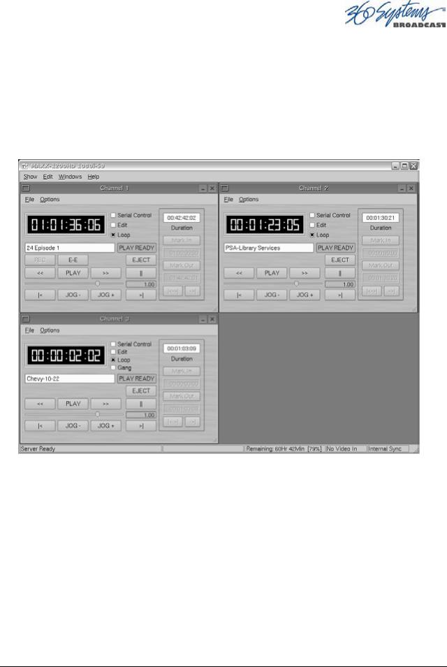
Graphic User Interface Overview
Once the server has successfully powered up, the VGA monitor will display the GUI of Figure 1. This view provides
•A main System Menu bar for configuration operations
•A Status Bar that displays various system messages
•Three VTR-like transport controls, one for each of the three video channels.
Figure 1: Graphic User Interface with Clip Transport Windows
When using the mouse, all buttons of all channels will operate immediately, without first selecting a window to activate it. (Channel 3 is active in the illustration above, indicated by its blue title bar.)
When using key commands, the active window is the only transport that will respond. Use the CTRL+TAB key combination to change the active window in rotation, or use the mouse to activate the desired window by clicking anywhere in it.
Windows can be moved, resized and overlapped by dragging the title bar, the edges or the resize tab at the lower right corner of each window. The CTRL+TAB key combination will also bring the activated window to the top, in front of all other windows.
MAXX-1200 Owner’s Manual |
Page 29 |
 Loading...