


TCR™ Series
User's Manual
Professional Production Recorders
TCR™ Series  User's Manual
The information contained in this User’s Manual is subject to change without notice or obligation, and is furnished for informational use only.
User’s Manual Edition 1.3, October 28, 1999.
Software version 1.0xx
© 1999, 360 Systems. Printed in the United States of America. All rights reserved.
Contents of this publication may not be reproduced in any form without the written permission of 360 Systems. Reproduction or reverse engineering of copyrighted software is prohibited. Software contained in this product is copyrighted by 360 Systems. Designs incorporated in this product are the subject of current or pending USA and foreign patents.
Company Address
Please use the following addresses for shipping and correspondence. At the Corporate Office in California, the switchboard is open Monday through Friday, from 8:00 AM to 5:00 PM.
Corporate Office and Customer Services |
European Office |
5321 Sterling Center Drive |
H. Meijerstraat 13 |
Westlake Village, CA 91361-4613 USA |
1444HA Purmerend, Netherlands |
Telephone: (+1) 818-991-0360 |
Telephone: (+31) 2994-37250 |
Fax: (+1) 818-991-1360 |
Fax: (+31) 2994-33627 |
E-mail info@360systems.com |
Website www.360systems.com |
Warning Symbols
The following warning symbols are used on the product in this manual:
English |
ATTENTION: Refer to Owner’s Manual for important information |
|
|
Français |
ATTENTION: Veuillez vous référer au Mode d’Emploi pour une information |
|
importante. |
|
|
Italiano |
ATTENZIONE: Fate riferimento al manuale per informazioni importanti. |
|
|
Español |
ATENTCION: Favor de referir al manual de operacion por informacion |
|
importante. |
|
|
|
|
English |
WARNING: Electrical shock hazard. |
|
|
Français |
AVERTISSEMENT: Danger de choc électrique. |
|
|
Italiano |
AVVERTIMENTO: Pericolo di shock elettrico. |
|
|
Español |
ADVERTENSIA: Peligro de choque electrico. |
|
|
Cautions
Please heed the following important cautions regarding the TCR4 and TCR8:
∙Do not remove the cover. No user serviceable parts inside. Refer servicing to qualified service personnel.
∙The TCR4 and TCR8 recorders contain a hard disk drive. While today’s hard disks are very reliable, they may be vulnerable to shock. Please handle with care, and exercise caution not to drop or bump the TCR recorder — damage to the internal hard disk may result. Ensure that power is off before moving the unit.
∙To reduce the risk of fire or electric shock, do not expose this unit to rain or moisture.

Contents
Introduction |
1-1 |
A Word of Thanks ........................................................................ |
1-1 |
In This Manual.............................................................................. |
1-1 |
Introducing the TCR Production Recorders ................................ |
1-2 |
Choice of TCR Models ......................................... |
1-2 |
Product Highlights........................................................................ |
1-3 |
TCR Options....................................................... |
1-4 |
Overview |
2-1 |
Control Panel Description............................................................ |
2-2 |
Monitoring Section............................................... |
2-3 |
Time Code Display............................................... |
2-3 |
Main Display ...................................................... |
2-4 |
Contrast Adjustment............................................. |
2-4 |
Keypad Section ................................................... |
2-4 |
Headphone Jack................................................... |
2-7 |
ZIP® Drive........................................................ |
2-8 |
Function Key Section............................................ |
2-8 |
Transport Control Section.......................................................... |
2-10 |
Drive Bay.......................................................... |
2-11 |
Jog Section ........................................................ |
2-11 |
Power Switch..................................................... |
2-13 |
Rear Panel Description.............................................................. |
2-14 |
Cooling Fan ....................................................... |
2-15 |
AC Power.......................................................... |
2-15 |
Ground Post....................................................... |
2-15 |
Sync and Time Code Section................................. |
2-15 |
Control Section................................................... |
2-16 |
Digital Audio Outputs.......................................... |
2-17 |
Digital Audio Inputs ............................................ |
2-17 |
Analog Audio Outputs ......................................... |
2-17 |
Analog Audio Inputs............................................ |
2-17 |
TCR Menu System..................................................................... |
2-18 |
Menu Navigation ........................................................................ |
2-19 |
Introduction to the Drive List...................................................... |
2-20 |
About the Drive Menu ......................................... |
2-20 |
Introduction to the Directory List................................................ |
2-21 |
About the Directory Menu .................................... |
2-21 |
TCR Series User's Manual |
Contents i |

Introduction to the File List......................................................... |
2-22 |
Auditioning a File ............................................... |
2-23 |
About the File Menu............................................ |
2-23 |
Introduction to the Transport Screen......................................... |
2-24 |
Opening a File.................................................... |
2-24 |
The Transport Menu ............................................ |
2-26 |
Locate Value Prompt ........................................... |
2-27 |
Adjusting Values ................................................ |
2-27 |
Installation |
3-1 |
Unpacking and Inspection ........................................................... |
3-2 |
Preparing Your Site...................................................................... |
3-2 |
Installing Hardware ...................................................................... |
3-3 |
Safety Cautions ................................................... |
3-3 |
Connecting Signals...................................................................... |
3-4 |
Audio I/O Connection........................................... |
3-4 |
Digital I/O Connection.............................. |
3-4 |
Analog I/O Connection.............................. |
3-4 |
Sync and Reference Connections............................. |
3-4 |
VITC Connection ..................................... |
3-5 |
Video Connection..................................... |
3-5 |
LTC Connection....................................... |
3-5 |
Word Clock Connection ............................ |
3-5 |
Control Connection .............................................. |
3-6 |
P2 Connection......................................... |
3-6 |
SCSI Connection...................................... |
3-6 |
GPI/O Connection.................................... |
3-6 |
Control In Connection .............................. |
3-6 |
Control Out Connection ............................ |
3-6 |
Operations |
4-1 |
24 Hour Time Line Concept......................................................... |
4-2 |
Machine Setup for Play and Record............................................ |
4-2 |
Sync Reference................................................. |
4-2 |
Frame and Sample Rates................................... |
4-3 |
External Sync Validity Indicators......................... |
4-3 |
Setting Up to Record.................................................................... |
4-3 |
Audio Input Selection ......................................... |
4-3 |
Sample Rate Conversions.................................. |
4-4 |
Track Arming..................................................... |
4-4 |
Track Monitoring, Metering and Muting................ |
4-5 |
Monitoring and Muting Rules .................. |
4-5 |
Monitoring and Metering Rules ............... |
4-6 |
Headroom Selection .......................................... |
4-6 |
Crossfade Time ................................................. |
4-6 |
Process Delays.................................................. |
4-6 |
RMW Selection.................................................. |
4-7 |
Basic Recording........................................................................... |
4-8 |
Full Record........................................................ |
4-8 |
Punch-In Record................................................ |
4-8 |
Punch-In Recording using the Arm Buttons ......... |
4-8 |
Automatic Edit Point Updates ............................. |
4-8 |
ii Contents |
TCR Series User's Manual |

Automatic Recording.................................................................... |
4-8 |
Setting Edit Points ............................................. |
4-8 |
Selecting Pre-roll and Post-roll Duration .............. |
4-9 |
Auto Record ...................................................... |
4-9 |
Recording from the File List......................................................... |
4-9 |
Playback....................................................................................... |
4-9 |
Locating Audio in the File ................................... |
4-9 |
Jog Mode.............................................. |
4-9 |
Shuttle Mode........................................ |
4-10 |
Fast Forward and Rewind...................... |
4-10 |
Changing the Rewind Speed ................. |
4-10 |
Using the Locate Register ................................. |
4-11 |
Entering Locate Values Directly ............. |
4-11 |
Adjusting Locate Values Using the Knob 4-11 |
|
Capturing Locate Values ....................... |
4-11 |
Storing and Recalling Locate Values...... |
4-11 |
Locating............................................... |
4-12 |
Naming Locates.................................... |
4-12 |
Review Playback .............................................. |
4-12 |
Edit Points............................................ |
4-12 |
Pre-roll and post-roll duration................. |
4-13 |
Performing the Review.......................... |
4-13 |
Variable-Speed Playback .................................. |
4-13 |
Initiating Off-Speed Playback................. |
4-13 |
Adjusting the Playback Speed ............... |
4-13 |
Digital Output Dithering ..................................... |
4-13 |
Chasing External Time Code..................................................... |
4-14 |
Time Code Input Selection ................................ |
4-14 |
Time Code and Sync Reference Relationships ... |
4-14 |
Internal Time Code Generator ........................... |
4-15 |
Chase Modes ................................................... |
4-15 |
Chase What ......................................... |
4-15 |
Chase When ........................................ |
4-15 |
Chase Until .......................................... |
4-15 |
Time Code Output ............................................ |
4-16 |
Output Options ..................................... |
4-16 |
Level Adjustment .................................. |
4-16 |
Time Code Offsets............................................ |
4-16 |
Entering an Offset................................. |
4-16 |
Capturing an Offset............................... |
4-16 |
Enabling the Offset ............................... |
4-16 |
Storing and Recalling Offsets ................ |
4-17 |
Naming Offsets..................................... |
4-17 |
Track Slip......................................................... |
4-17 |
Time Code Display Options ............................... |
4-18 |
Starting a Chase Operation ............................... |
4-18 |
Punching In and Out During Chase.................... |
4-18 |
Auto-Recording During Chase ........................... |
4-18 |
Reviewing During Chase................................... |
4-18 |
Synchronizing Multiple TCRs............................. |
4-19 |
Off-line Editing Operations......................................................... |
4-20 |
Erase Edit-In through Edit-Out........................... |
4-20 |
Copy Edit-In through Edit-Out............................ |
4-22 |
Cut Edit-In through Edit-Out............................... |
4-25 |
Paste at Edit-In................................................. |
4-28 |
Insert in Front of Edit-In..................................... |
4-30 |
TCR Series User's Manual |
Contents iii |

Saving Your Work ...................................................................... |
4-34 |
Changing the Removable Drive ......................... |
4-34 |
Changing a Zip Disk.......................................... |
4-34 |
Machine Setup |
5-1 |
Setup Menu Functions................................................................. |
5-2 |
Preferences.................................................................................. |
5-3 |
Crossfade ........................................................... |
5-4 |
Pre-Roll ............................................................. |
5-5 |
Post-Roll ............................................................ |
5-5 |
Sort Files By ....................................................... |
5-5 |
File Info to Show ................................................. |
5-6 |
Directory Info to Show.......................................... |
5-6 |
Drive Info to Show............................................... |
5-7 |
Default Time....................................................... |
5-7 |
Default Tracks..................................................... |
5-8 |
Default Title........................................................ |
5-8 |
Typed Time Values .............................................. |
5-9 |
Rewind/FF Speed................................................ |
5-10 |
Prompt on Exit ................................................... |
5-10 |
Screen Saver Off................................................. |
5-10 |
Audio I/O .................................................................................... |
5-12 |
Track Input........................................................ |
5-13 |
Sample Rate Converter Input................................. |
5-13 |
Monitor Armed Tracks......................................... |
5-14 |
Output Word Size ............................................... |
5-14 |
Headroom.......................................................... |
5-14 |
Calibrate Outputs................................................ |
5-15 |
Calibrate Inputs .................................................. |
5-15 |
Set Process Delays .............................................. |
5-15 |
Sync and Time Code ................................................................. |
5-16 |
Sync Ref ........................................................... |
5-17 |
Rate/Format....................................................... |
5-18 |
TC Input............................................................ |
5-18 |
LTC Level......................................................... |
5-19 |
Output LTC ....................................................... |
5-19 |
Chase What ....................................................... |
5-19 |
Chase When....................................................... |
5-20 |
Chase Until........................................................ |
5-20 |
Generator .......................................................... |
5-20 |
Set Generator ..................................................... |
5-21 |
External Control ......................................................................... |
5-22 |
Control-In Port ................................................... |
5-22 |
RS-422 Emulation............................................... |
5-23 |
RS-422 Ballistics ................................................ |
5-23 |
RS-422 Track Arming.......................................... |
5-23 |
General Purpose I/O ............................................ |
5-25 |
iv Contents |
TCR Series User's Manual |

Drives ......................................................................................... |
5-27 |
Recall Machine Setup................................................................ |
5-28 |
Store Machine Setup ................................................................. |
5-29 |
Use Factory Defaults ................................................................. |
5-30 |
System Management |
6-1 |
Using the Keypad for Renaming.................................................. |
6-2 |
Drive Menu Functions.................................................................. |
6-3 |
Machine Setup .................................................. |
6-3 |
Rename Drive ................................................... |
6-3 |
Erase Drive ....................................................... |
6-4 |
Copy Drive ........................................................ |
6-5 |
Spin Up Drive .................................................... |
6-6 |
Spin Down Drive................................................ |
6-6 |
Install File System.............................................. |
6-7 |
Check Disk........................................................ |
6-8 |
Format Drive ..................................................... |
6-8 |
Directory Menu Functions.......................................................... |
6-10 |
Machine Setup ................................................. |
6-10 |
Rename Directory............................................. |
6-10 |
Erase Directory................................................. |
6-11 |
Copy Directory.................................................. |
6-11 |
File Menu Functions................................................................... |
6-13 |
Machine Setup ................................................. |
6-13 |
Rename File..................................................... |
6-14 |
Erase Files....................................................... |
6-14 |
Copy Files........................................................ |
6-15 |
Change File Index............................................. |
6-16 |
Create New File................................................ |
6-17 |
Lock Files......................................................... |
6-18 |
Mark Files ........................................................ |
6-18 |
Installing TCR Program Updates............................................... |
6-19 |
Appendix A. VTR Emulation and Remote Control |
7-1 |
Machine I.D. Number................................................................... |
7-2 |
Emulating VTRs ........................................................................... |
7-2 |
Serial Control Protocol................................................................. |
7-2 |
Appendix B. Maintenance |
8-1 |
Calibration Procedure .................................................................. |
8-2 |
Output Calibration................................................ |
8-2 |
Input Calibration.................................................. |
8-4 |
Calibration Accuracy.................................................................... |
8-5 |
Input Gain Accuracy............................................. |
8-5 |
Output Gain Accuracy .......................................... |
8-5 |
TCR Series User's Manual |
Contents v |

Cleaning ....................................................................................... |
8-6 |
Appendix C. Specifications |
9-1 |
General Specifications................................................................. |
9-2 |
Audio Specifications..................................................................... |
9-3 |
Mechanical Specifications ........................................................... |
9-4 |
Audio I/O Connector Pinouts ....................................................... |
9-4 |
Control Input and Output Connector Pinouts .............................. |
9-5 |
P2 Connector Pinouts.................................................................. |
9-5 |
GPI/O Connector Pinouts ............................................................ |
9-6 |
AC Power Connector Pinouts...................................................... |
9-6 |
Appendix D. Mechanical Drawings |
10-1 |
Index |
11-1 |
vi Contents |
TCR Series User's Manual |

TCR Series User's Manual |
Contents vii |

Safety Compliance
TCR is currently being investigated for compliance with the following safety standards:
∙UL 1950, Standard for Safety of Information Technology Equipment, Including Electrical Business Equipment.
∙EN 60950, Standard for Safety of Information Technology Equipment, Including Electrical Business Equipment.
EU Declaration of Conformity
Type of Equipment: Professional Use Audio Equipment.
Conforms to the Following Standards:
∙EN55022 (1995) with amendments 1 and 2
(Limits and methods of measurement of radio disturbance characteristics of information technology equipment)
∙EN50082-1 (1997) (Generic immunity standard, Part 1: Residential, commercial and light industry).
∙IEC950 2nd Edition, Amendment 1 (1992), Amendment 2 (1993) and Amendment 3 (1995); Safety of Information Technology and Business Equipment.
FCC Compliance
This equipment complies with Part 15 of the FCC Rules. These limits are designed to provide reasonable protection against harmful interference when the equipment is operated in a commercial environment. This equipment generates, uses and can radiate radio frequency energy and if not installed and used in accordance with the owners manual, may cause interference to radio communications. Operation of this equipment in a residential area is likely to cause interference in which case the user will be required to correct the interference at his own expense.
This device will accept any interference received, including interference that may cause undesired operation. The user is cautioned that changes made to the equipment without the approval of the manufacturer could void the user's authority to operate this equipment. It is suggested that only shielded and grounded cables be used to ensure compliance with FCC Rules.
Notice
This Class A digital apparatus meets all requirement of the Canadian Interference-Causing Equipment Regulations.
Français: Cet appariel numérique de la classe A respecte toute les exigences du Reglement sur le matériel brouilleur du Canada.
viii Compliance |
TCR Series User's Manual |
Warranty and Repair Policy
TCR4 and TCR8 are warranted against defects in material and workmanship for a period of one year from date of original purchase. This warranty includes parts and labor. This warranty excludes units that have been modified, repaired by unauthorized personnel, or damaged by rough handling, abuse, improper operation, dirt, or static electricity.
360 Systems assumes no liability whatsoever for real or consequential damages, loss of profits, inconvenience or any other losses due to non-operation of the TCR4 and TCR8 recorders. 360 Systems’ sole liability under this limited warranty shall be the repair or replacement of defective product or components. Products being returned under warranty shall be sent to 360 Systems or one of its foreign service centers, freight prepaid, in the original or equivalent packaging. Please call 360 Systems for a return authorization number before returning any merchandise for any reason.
Product Improvements and Upgrades
360 Systems reserves the right to make changes and/or improvements to its products, without incurring any obligation to incorporate such changes or improvements in units previously sold or shipped.
Trademarks
The following trademarks may appear in this manual:
∙ is a registered trademark of 360 Systems.
∙TCR, TCR4 and TCR8 are trademarks of 360 Systems.
∙Zip® is a registered trademark of Iomega Corp.
∙Flex® is a registered trademark of Altera Corp.
∙All other product and brand names and any registered and unregistered trademarks mentioned in this manual are used for identification purposes only and remain the exclusive property of their respective owners.
TCR Series User's Manual |
Notices ix |

TCR Series User's Manual

`Introduction
A Word of Thanks
Thank you and congratulations on choosing 360 Systems’ TCR™ Series synchronous digital multitrack production recorder. You have purchased the power, versatility and creativity of the industry’s leading digital multi-track audio recorder — a system ready to take on all creative challenges in today’s competitive production environments.
You’ll be pleased at how easily the TCR integrates into your overall working environment — and the marked increase in the quality and quantity of your production.
Product Registration
Important — Please take a moment now to fill out your Warranty Card and either mail it, or fax it to 360 Systems Offices in the USA. By completing your Warranty Card, you will be able to receive new software upgrades and periodic Technical Support Bulletins about product enhancements and upgrades. Your warranty registration is the only way we know that you own a TCR.
In This Manual
This manual provides installation, setup and operating instructions for 360 Systems’ TCR Series of digital audio production recorders. Instructions are provided for both the TCR4 and the TCR8.
TCR recorders perform the complex tasks of synchronous audio production and editing — using a well designed, simple-to-use set of menus and buttons. This manual is organized to provide the user with a quick understanding of how to use the TCR to accomplish those production and editing tasks.
If you are already familiar with synchronous audio production, you should find TCR to be nearly intuitive. As such, an extensive index is provided at the end of this manual to assist you in locating information quickly.
However, we recommend that you read the entire manual so that you will become familiar with all of the features and helpful tools built into the TCR — each of which is designed to make your use of the TCR more productive and enjoyable.
TCR Series User's Manual |
`Introduction 1-1 |

Introducing the TCR Production Recorders
In the realm of audio recording, 360 Systems’ family of synchronous audio recorders represents a “next generation” technical development. Moving beyond “tapeless,” the TCR series couples an entirely new machine architecture with the feature set most requested by industry professionals.
The TCR4 and TCR8 are production recorders, designed specifically for television broadcast, video production and professional audio recording. As professional grade machines, they deliver premium quality audio and precise time code synchronization in a robust, carefully engineered package.
∙Speed and Versatility
The TCR’s design introduces speed and versatility to a variety of audio tasks. TCR recorders are not just “playout” machines for dubbing — they include many production features such as auto-locate, seamless punch-in, read-modify-write (RMW), looping, editing and offsets — features that make the TCR a first choice as the primary studio recorder.
∙24-bit Performance
To deliver the 24-bit performance expected of a new generation product, 360 Systems has designed entirely new “ultra-low jitter” clock generation circuits. In addition to professional analog and digital input circuitry, XLR connectors are provided as standard.
∙A Versatile Platform
With the industry in transition in regard to file formats and media, the TCR is built to accept many kinds of media and play many types of files. Using TCR, files will be able to be directly transferred to and from leading workstations, on media of the user’s choice.
Choice of TCR Models
360 Systems offers two TCR models, each designed for different audio production requirements.
∙Model TCR8 Eight Track Recorder
The TCR8 is designed for synchronous recording and playback in video, television production, cinema sound and broadcast applications. The TCR8 is also the ideal choice for surround-sound production, handling six channels (5.1) plus Lt-Rt. As a fast non-linear recorder, TCR8 is a natural upgrade from tape, and provides easy file interchange with popular workstations.
As your primary studio and mastering machine, TCR8 functions in standalone mode or, in the future, it can be combined with up to seven other recorders for transparent 64-track operation using the TCR’s multi-machine sync bus. Time code gives the TCR8 unprecedented editing power, including automated punch-in punch-out capability with variable length crossfade and Undo. Best of all, and unlike any other system, the TCR8 can record an entire working day of 24-bit audio — without reloading media.
∙Model TCR4 Four Track Recorder
The TCR4 precisely answers the need for a machine to replace time code DAT and “audioonly” VTRs. It includes the third and fourth tracks so often needed in video production, and provides greatly improved audio quality, cost-effective removable media and the instant response of a hard-disk recorder. Most important, TCR4 delivers a degree of reliability unattainable with tape-based systems.
Note that recorded files and sync connections are compatible between the TCR4 and TCR8.
1-2 ‘Introduction |
TCR Series User's Manual |

Product Highlights
This section outlines many of the superb features designed into the TCR series of digital multi-track recorders. All of these features apply to both the TCR4 and TCR8.
∙Unlimited Storage
Today’s projects result in very large audio files, particularly when they are multi-track, 24bit, or recorded at high sample rates. With the advent of affordable very high capacity drives, the file size limitation has been removed. TCR can accept an internal hard disk of unlimited size, with individual file size extending to the 24-hour limit of SMPTE/EBU time code.
∙High Density Removable Media
TCR recorders include a 250 MB Zip® drive as standard equipment. Each 250 MB Zip® cartridge provides a half-hour of low-cost file storage. Additionally, a 5_" drive bay accepts many user-selected drives, including removable hard disks, magneto-optical disks, and the emerging ultra-high density cartridges. A rear-panel SCSI port connects as many as five additional drives to the TCR system.
∙Programmable Hardware
360 Systems brings an entirely new design concept to the TCR platform — Programmable Hardware. To allow the system to be reconfigured as needs arise, much of TCR’s internal architecture is built with programmable Flex® logic, which can be reconfigured under software control. Using the built-in Zip drive, new hardware and software tools can be loaded. Overall, this superb capability means that TCR can be upgraded, modified and reconfigured with minimal disruption to your schedule.
∙Word Size Flexibility
As top quality audio becomes an increasing priority in the entertainment industry, 360 Systems selected 24-bits as the standard word size for all TCR recordings. However, optional 16 and 20-bit digital outputs can be generated for compatibility with older equipment.
∙Control Panel Clarity
The TCR’s control panel is designed for ease-of-use, with features specifically tailored for audio and video professionals. The large illuminated LCD screen provides clear and concise data for each system mode, including file names, machine status, edit operations, task prompts and operator “alerts.” A separate large LED readout is provided for clarity in reading time code position. For metering, a precise 14-segment LED meter array shows each channel’s level. For further operator comfort, intuitive VTR-like controls including the familiar Jog/Shuttle Wheel are provided.
∙Time Code Synchronization
TCR recorders include a complete set of SMPTE-EBU time code capabilities. They can lock to all common NTSC and PAL sync formats, including VITC, LTC, word clock, AES/EBU, internal crystals, or the multi-machine bus. Sample and playback rates can incorporate a ±0.1% pull-up or pull-down to accommodate any format conversion.
TCR Series User's Manual |
`Introduction 1-3 |

∙Standard Editing Functions
The TCR series includes a standard array of editing functions, including Cut, Copy, Insert, Paste, Erase and time offsets for individual tracks and for the entire machine. The convenient Jog Wheel, interactive LCD screen and track markers all combine to make editing easy. In addition, there’s an UNDO button for quickly correcting mistakes.
∙Remote Control Capability
All TCR recorders include a 9-pin serial port for seamless interfacing with edit controllers — just like a VTR. Using standard RS-422 VTR control protocol, the TCR provides the instant response of a non-linear recorder when used in a multi-machine editing configuration. TCR can emulate several common types of VTR and Time Code DAT transports.
TCR Options
TCR recorders may be configured with a choice of high-capacity drives for both the internal drive and the optional drive in the Drive Bay.
The following table lists recording times for each size drive including the standard 250 MB Zip® drive, in various multi-track recording modes. The recording times listed are approximate, and are based on continuous recording of all tracks simultaneously. Use of fewer tracks, or intermittent audio, will yield an increase in the available storage time.
Calculated TCR4 and TCR8 Recording Times at 48kHz Sample Rate
Track Count |
250 MB |
9 GB |
18 GB |
36 GB |
50 GB |
|
Zip Disk |
Hard Disk |
Hard Disk |
Hard Disk |
Hard Disk |
Eight Track Recording |
3 min. 20 sec |
2 hr 10 min. |
4 hr 20 min. |
8 hr 40 min. |
12 hr 3 min. |
Four Track Recording |
6 min. 52 sec |
4 hr 20 min. |
8 hr 40 min. |
17 hr 21 min. |
24 hr 6 min. |
Two Track Recording |
14 min. 10 sec |
8 hr 40 min. |
17 hr 21 min. |
34 hr 43 min. |
48 hr 13 min. |
Single Track (mono) |
28 min. 20 sec |
17 hr 20 min. |
34 hr 42 min. |
69 hr 26 min. |
96 hr 26 min. |
|
|
|
|
|
|
Important The Drive Bay assembly, including the drawer, drive and associated connectors, is an optional item that should be pre-configured at 360 Systems’ factory. If you wish to upgrade your system to include an optional drive for the Drive Bay, please contact 360 Systems Customer Support at the location listed in the front of this manual. Only qualified service personnel should perform the upgrade procedure.
1-4 ‘Introduction |
TCR Series User's Manual |

Overview
In This Chapter
The operating philosophy of the TCR™ recorder is presented here, with an eye to giving the reader a view of what can be accomplished without going into fine detail about its how each task is performed. It is our intention to convey the “design idea” for the machine, so the user can work on the same level as TCR’s design group.
Important This chapter should be reviewed before proceeding to the Operations chapter.
∙The buttons, displays, and disk drives on the front panel will be presented, and their functions will be defined.
∙Rear panel components such as connectors and switches are described as they relate to the TCR’s capabilities.
∙This chapter presents an introduction to the TCR’s menu system, and explains how the control panel is used for navigation.
TCR Series User's Manual |
Overview 2-1 |

Control Panel Description
The TCR4 and TCR8 control panels are divided into sections intended to logically group related controls together. Except for the Monitoring Section, the panel sections are identical between models.
1 |
|
|
|
|
|
|
|
3 |
2 |
4 |
|
|
5 |
|
|
|
|
|
|
|
|
|
|
|
TC LOCK |
EXT SYNC |
|
|
|
|
|
|
|
|
|
|
|
|
|
CLIP |
|
CAPTURE |
7 |
8 |
9 |
MENU |
DIR |
|
|
|
|
|
|
|
|
+18 |
|
MARK |
ABC |
DEF |
GHI |
DRIVES |
|
|
|
|
|
|
|
|
|
+15 |
|
|
|||||
|
|
|
|
|
|
|
|
|
|
|
|
||||
|
|
|
|
|
|
|
|
+12 |
|
|
|
|
|
|
|
|
|
|
|
|
|
|
|
+9 |
|
|
|
|
|
|
|
|
|
|
|
|
|
|
|
+6 |
|
|
4 |
5 |
6 |
|
|
|
|
|
|
|
|
|
|
+3 |
|
LOCATE |
EXIT |
FILES |
|||
|
|
|
|
|
|
|
|
0 |
|
FIND |
|
VERS |
|||
|
|
|
|
|
|
|
|
-10 |
|
JKL |
MNO |
PQR |
|
||
|
|
|
|
|
|
|
|
-20 |
|
|
|
|
|||
|
|
|
|
|
|
|
|
-30 |
|
|
|
|
|
|
|
|
|
|
|
|
|
|
|
-40 |
|
|
|
|
|
|
|
|
|
|
|
|
|
|
|
-50 |
|
STORE |
1 |
2 |
3 |
|
SAVE |
|
|
|
|
|
|
|
|
-70 |
|
ENTER |
|||||
|
|
|
|
|
|
|
|
|
|
PG UP |
LOCK |
||||
|
|
|
|
|
|
|
|
SLIP |
|
STU |
VWX |
YZ/ |
|
||
1 |
2 |
3 |
4 |
5 |
6 |
7 |
8 |
ARM |
|
RECALL |
+/- |
0 |
CLEAR |
|
UNDO |
|
|
|
|
|
|
|
|
ALL |
|
PG DN |
* |
SYM |
SPACE |
|
REDO |
|
|
|
|
|
|
|
|
|
|
|
|
|
|
||
MON |
MON |
MON |
MON |
MON |
MON |
MON |
MON |
ALL |
|
|
|
|
|
|
|
|
|
|
|
|
|
|
|
INPUT |
|
|
|
|
|
|
|
|
R-M-W |
MUTE |
LOOP |
REMOTE |
OFFSET |
|
|
|
ALT |
ADJ - |
|
|
|
ADJ + |
SHTL |
|
|
|
|
|
PLAY |
STOP |
REC |
AUTO |
REVIEW |
|
|
|
|
||
|
|
|
|
|
|
|
|
|
|
|
|||||
|
VARI |
OPT |
SLIP |
DISP |
CHASE |
|
|
|
ADJUST |
EDIT IN |
|
|
|
EDIT OUT |
|
6 |
7 |
|
|
8 |
9 |
|
|
|
10 |
11 |
|
|
|
|
12 |
|
|
|
|
|
TCR8 Control Panel Sections |
|
|
|
|
|
|
||||
1 |
|
|
|
3 |
2 |
|
|
|
|
4 |
|
|
5 |
|
|
|
|
|
|
|
TC LOCK |
|
|
|
EXT SYNC |
|
|
|
|
|
|
|
|
|
CLIP |
|
|
|
|
|
|
CAPTURE |
7 |
8 |
9 |
MENU |
DIR |
|
|
|
+18 |
|
|
|
|
|
|
MARK |
ABC |
DEF |
GHI |
DRIVES |
|
|
|
|
+15 |
|
|
|
|
|
|
|
|||||
|
|
|
|
|
|
|
|
|
|
|
|
||||
|
|
|
+12 |
|
|
|
|
|
|
|
|
|
|
|
|
|
|
|
+9 |
|
|
|
|
|
|
|
|
|
|
|
|
|
|
|
+6 |
|
|
|
|
|
|
|
4 |
5 |
6 |
|
|
|
|
|
+3 |
|
|
|
|
|
|
LOCATE |
EXIT |
FILES |
|||
|
|
|
0 |
|
|
|
|
|
|
FIND |
|
VERS |
|||
|
|
|
-10 |
|
|
|
|
|
|
JKL |
MNO |
PQR |
|
||
|
|
|
-20 |
|
|
|
|
|
|
|
|
|
|||
|
|
|
-30 |
|
|
|
|
|
|
|
|
|
|
|
|
|
|
|
-40 |
|
|
|
|
|
|
|
|
|
|
|
|
|
|
|
-50 |
|
|
|
|
|
|
STORE |
1 |
2 |
3 |
|
SAVE |
|
|
|
-70 |
|
|
|
|
|
|
ENTER |
|||||
|
|
|
|
|
|
|
|
|
|
PG UP |
LOCK |
||||
|
|
|
SLIP |
|
|
|
|
|
|
STU |
VWX |
YZ/ |
|
||
|
|
|
ARM |
|
|
|
|
|
|
|
|
|
|
|
|
|
1 |
2 |
3 |
4 |
|
|
|
|
|
RECALL |
+/- |
0 |
CLEAR |
|
UNDO |
|
|
|
|
|
|
|
|
|
|
PG DN |
* |
SYM |
SPACE |
|
REDO |
|
|
|
|
|
|
|
|
|
|
|
|
|
|
||
|
|
|
INPUT |
|
|
|
|
|
|
|
|
|
|
|
|
|
MON |
MON |
MON |
MON |
|
|
|
|
|
|
|
|
|
|
|
|
R-M-W |
MUTE |
LOOP |
REMOTE |
OFFSET |
|
|
|
ALT |
ADJ - |
|
|
|
ADJ + |
SHTL |
|
|
|
|
|
PLAY |
STOP |
REC |
AUTO |
REVIEW |
|
|
|
|
||
|
|
|
|
|
|
|
|
|
|
|
|||||
|
VARI |
OPT |
SLIP |
DISP |
CHASE |
|
|
|
ADJUST |
EDIT IN |
|
|
|
EDIT OUT |
|
6 |
7 |
|
|
8 |
9 |
|
|
|
10 |
11 |
|
|
|
|
12 |
TCR4 Control Panel Sections
1) |
Monitoring Section |
5) |
Keypad Section |
9) |
Transport Control Section |
2) |
Time code Display |
6) |
Headphone Jack |
10) |
Drive Bay |
3) |
Main Display |
7) |
ZIP Drive |
11) |
Jog Section |
4) |
Contrast Adjustment |
8) |
Function Section |
12) |
Power Switch |
|
|
|
|
|
|
2-2 Overview |
TCR Series User's Manual |
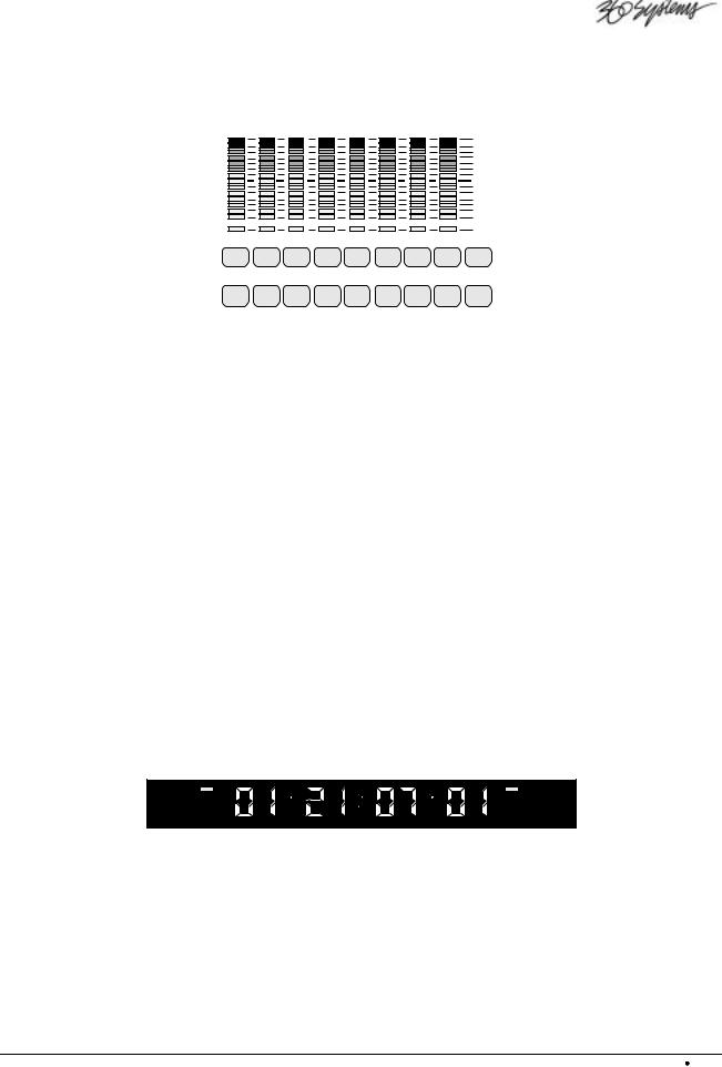
Monitoring Section
The Monitoring Section, as shown below for the TCR8, includes eight peak-responding audio level meters, plus buttons for arming tracks and monitoring their status.
CLIP +18 +15 +12 +9 +6 +3 0 -10 -20 -30 -40 -50 -70
|
|
|
|
|
|
|
|
SLIP |
1 |
2 |
3 |
4 |
5 |
6 |
7 |
8 |
ARM |
|
|
|
|
|
|
|
|
ALL |
MON |
MON |
MON |
MON |
MON |
MON |
MON |
MON |
ALL |
|
|
|
|
|
|
|
|
INPUT |
LED VU Meters
Fourteen LEDs display the recording level, covering a range from +20 dB to –70 dB. The headroom displayed between the “zero” reference and “clip” level can be programmed to conform to the common standards of 16 dB and 20 dB.
The CLIP LED lights when the input level for the associated track has peaked. It remains on until STOP, PLAY, ARM or MON is pressed.
The SLIP LED below the level display lights when that track has been offset in time with respect to others.
Track Arm Buttons
Eight numbered track ARM buttons are provided on the TCR8 — four on the TCR4. When lit RED, the selected tracks are armed for recording.
Monitor Buttons
Eight MON (monitor) buttons are provided on the TCR8 — four on the TCR4.
When MON is toggled on (RED) that channel’s input will be passed through to the output. When MON is toggled off, that channel’s output will be from disk.
Time Code Display
The Time Code Display provides several kinds of information, depending on the operating mode of the recorder. The display can present external time code, time code with offset, or the output of the internal time code generator.
TC LOCK |
EXT SYNC |
Two status LEDs are also provided in this section:
∙TC Lock — the TC LOCK LED lights whenever the TCR is locked to incoming time code, either LTC or VITC.
∙External Sync — the EXT SYNC LED lights whenever the TCR is referenced to an external sample rate. When this LED is off, the TCR is running on its internal sample rate reference.
TCR Series User's Manual |
Overview 2-3 |
Main Display
The TCR’s LCD Main Display provides information about the machine’s current mode of operation.
|
|
|
|
|
|
|
LOC |
01:00:01:21 .00 |
FILE |
|
|
|
POSN |
|
|||
|
FILE: ROUTE 66 |
|
|
|
|
|
|
EDIT IN |
: 01:00:01:21 |
|
|
|
|
EDIT OUT |
: 01:02:56:05 |
|
|
|
|
OFFSET |
: 00:00:00:00 |
|
|
|
|
FRAME RATE |
: 30 NON-DROP |
|
|
|
|
SAMPLE RATE |
: 48000 |
|
|
|
|
SYNC INPUT |
: INTERNAL |
|
|
|
|
TC SOURCE |
: VITC IF NO LTC |
|
|
|
TIME LEFT: 02:07:34 (8) |
SPEED: 0.000X |
|
||
|
|
|
|
|
|
|
|
|
|
|
|
Transport Screen
Four basic displays are provided, each with associated sub-menus: the Drive List, Directory List, File List and Transport Screen. Each of these will be introduced in detail later in this chapter.
Contrast Adjustment
Immediately below the RECALL button, a Contrast Adjustment is provided to adjust the LCD viewing angle for optimum legibility.
STORE |
1 |
PG UP |
STU |
|
|
RECALL |
+/1 |
PG DN |
* |
|
Contrast
Adjustment
A small flat-blade screwdriver or similar tool is needed for adjustment; one is shipped with each TCR.
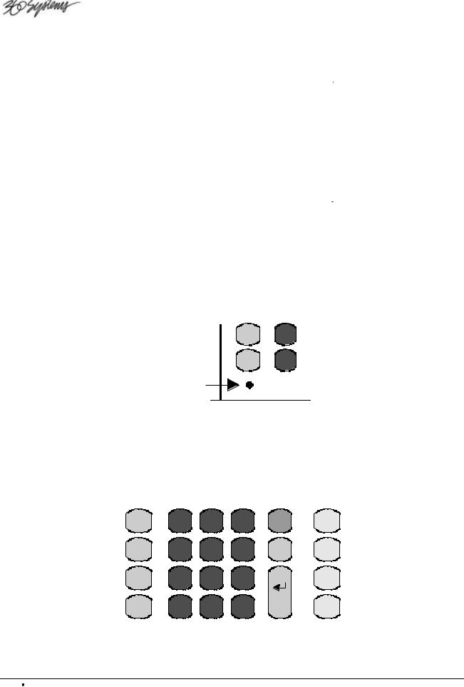
Keypad Section
The Keypad Section provides buttons for entering numbers, as in time-code values. It can also enter alphabetic characters, so that files may be given “real” names. Other buttons give fast access to Drives, Directories, Files and Menus.
CAPTURE |
7 |
8 |
9 |
MENU |
DIR |
MARK |
ABC |
DEF |
GHI |
|
DRIVES |
LOCATE |
4 |
5 |
6 |
EXIT |
FILES |
FIND |
JKL |
MNO |
PQR |
|
VERS |
STORE |
1 |
2 |
3 |
ENTER |
SAVE |
PG UP |
STU |
VWX |
YZ/ |
|
LOCK |
RECALL |
+/- |
0 |
CLEAR |
|
UNDO |
PG DN |
* |
SYM |
SPACE |
|
REDO |
|
|
|
|
|
2-4 Overview |
TCR Series User's Manual |
Many buttons have both large and small legends. These are dual-function — the key’s function depends on the context of the current operation. It is not necessary to use a “shift” key for the second command.
Capture / Mark
The CAPTURE button “grabs” a time code for use on the Transport Screen. When pressed, the value in the red Time Code Display is transferred to the Time Code Register on the Main display.
The MARK button places a checkmark (ü) after a filename on the File List. The marks are used to group files together for functions such as copy and erase.
Locate / Find
The LOCATE button instantly “cues” to the time code value shown in the Time Code Register.
The FIND button allows you to quickly find files. When pressed, the name of the desired file can be entered, and the file immediately retrieved.
Store / Page Up
The STORE button will store the time code value that currently appears in the Time Code Register, in a “Location Register”, so it may be retrieved for future use.
The PG UP (page up) button pages upward when a list is longer than the screen.
Recall / Page Down
The RECALL button allows you to recall a time code value from a Location Register, and place it in the Time Code Register.
The PG DN (page down) button pages downward when a list is longer than the screen.
Keypad / Alpha
TheKeypad is designed for both numeric and alphanumeric entry modes, depending upon the current operating context.
∙The KEYPAD buttons (0 through 9) will select numbered menu items directly, and enter time code values.
∙The KEYPAD buttons can also become ALPHA keys (ABC through YZ/), allowing files, drives, and directories to be given “real” names.
∙The +/- key toggles the Time Code Register between positive and negative values.
∙The * (star) key gives access to special Location Registers.
∙The SYM button allows you to enter special symbols that do not appear on the keypad’s ALPHA keys.
∙The CLEAR button clears the Time Code Register to 00:00:00:00.
∙In alphanumeric entry modes, the SPACE button enters a blank space.
Menu
The MENU button will present the menus associated with the Drive, Directory, File or Transport Screens.
TCR Series User's Manual |
Overview 2-5 |

Exit
The EXIT button has four primary functions:
∙To return from a menu back to its associated display
∙To return from a display back to the previous display in the menu system
∙To safely cancel a machine operation currently in progress
∙To end an editing session and close the file
Enter
The ENTER button confirms (or accepts) a data entry procedure. The button will also access a highlighted drive, directory, file or menu function.
Directory / Drives
The DIR button calls up a list of Drives or Directories, from which a selection can be made. The button is dual-function: pressing it once presents a Directory List; Pressing DIR again toggles to the Drive List.
As shown below, the Directory List presents all the Directory names for the selected drive.
DIRS ON: (HARD DRIVE 1)
0. |
(DIRECTORY 1.0) |
2 |
FILES |
1. |
(DIRECTORY 1.1) |
10 |
FILES |
2. |
(DIRECTORY 1.2) |
9 |
FILES |
3. |
(DIRECTORY 1.3) |
8 |
FILES |
4. |
(DIRECTORY 1.4) |
5 |
FILES |
5. |
(DIRECTORY 1.5) |
2 |
FILES |
6. |
(DIRECTORY 1.6) |
0 |
FILES |
7. |
(DIRECTORY 1.7) |
0 |
FILES |
8. |
(DIRECTORY 1.8) |
0 |
FILES |
9. |
(DIRECTORY 1.9) |
0 |
FILES |
'ENTER' OR NUMBER OPENS DIRECTORY
Directory List
As shown below, the Drive List presents all the Drive names currently on line in the TCR recorder.
DRIVES:
0. |
(ZIP DRIVE 0) |
0.0M FREE |
1. |
(HARD DRIVE 1) |
8.6G FREE |
2. |
(REMOVABLE DRIVE 2) |
9.1G FREE |
'ENTER' OR NUMBER SELECTS DRIVE 'EXIT' CHECKS FOR AVAILABLE DRIVES 'MENU' SHOWS DRIVE MENU
Drive List
2-6 Overview |
TCR Series User's Manual |

Files / Version
The FILES button calls up a list of files present.
As shown below, the File List presents all audio files, by name and index, present in the current directory. Additional information, such as time, can also be displayed.
FILES IN: (DIRECTORY 1.2)
000 |
FILE_000 |
00:03:02 |
|
|
001 |
FILE_001 |
00:02:37 |
|
|
002 |
DROP INS TK1 |
00:00:49 |
|
|
003 |
RERECORD 1-4 |
00:00:50 |
|
|
004 |
RERECORD 8-5 |
00:10:01 |
|
|
|
005 |
TK1 ONLY |
00:00:15 |
|
006 |
TK2 ONLY |
00:00:16 |
|
|
007 |
FILE_007 SIMUL 1-4 |
00:02:01 |
|
|
008 |
PGM OPEN TK1 |
00:30:10 |
|
|
|
|
|
|
|
File List
The TCR recorder offers a simple “Audition” Mode, allowing any file to be highlighted and played directly from the File menu. Just press PLAY.
The version button displays the software version number and machine I.D.
Save / Lock
The SAVE button will save a file you are working on, without closing it. The button lights as a reminder when changes have been made to the file.
The LOCK button changes the attributes of a file to “read-only,” and places a small Lock Icon (  ) on the display. In this mode, the file can be played but not altered.
Undo / Redo
The UNDO button will reverse the last operation and restore the previous version of a file. Whenever changes have been made to a file, the UNDO button lights to indicate that the operation may be undone.
The REDO button reverses the “undo” operation.
Headphone Jack
A standard 1/4" (6.3 mm) HEADPHONE JACK is provided on the left side of the front panel. The HEADPHONE button can be used in conjunction with the JOG WHEEL for convenient singlehanded level adjustment.
The headphone channel assignment is:
∙Tracks 1, 3, 5 and 7 to the left
∙Tracks 2, 4, 6 and 8 to the right.
The MON (monitor) buttons under the meters also function as channel-enable selectors for the headphones.
TCR Series User's Manual |
Overview 2-7 |
ZIP Drive
Drive
A 250 MB ZIP® Drive is provided as standard equipment on the front panel.
The drive may be used as an audio source, and for economical storage of small projects.
Approximately 14 track-minutes of 24-bit audio can be stored on a 250 MB Zip® disk. It is also used to load new TCR operating software.
Function Key Section
The function key section provides an array of ten buttons:
R-M-W |
MUTE |
LOOP |
REMOTE |
OFFSET |
VARI |
OPTION |
SLIP |
DISP |
CHASE |
R-M-W
When Read-Modify-Write is enabled, only playback audio is available at a channel output, rather than the usual input signal. Audio may then be externally modified and re-recorded to disk, all in a single operation. The R-M-W button toggles the mode on and off.
Varispeed Play
When Varispeed playback is active, audio is played at an adjustable off-speed rate. Varispeed processing is accomplished by the DSP so that a standard output sample rate is always produced. The VARI button toggles varispeed mode on and off.
Mute
The MUTE button toggles the track Mute function on and off.
∙When MUTE is on, the MON buttons are re-defined as MUTE buttons. When a track is muted, its meters still function in the record mode.
∙When MUTE is turned off, any tracks that had been muted will remain muted, and blink their MON buttons as a reminder. All other MON buttons return to their standard purpose.
Option
This is a “spare” button for future use. It is presently used for Lamp Test whenever the File List is displayed.
Loop
When LOOP is active, playback will repeat indefinitely, with a small pause between cycles. The LOOP button toggles the Loop Mode on and off.
2-8 Overview |
TCR Series User's Manual |

Slip
The SLIP button allows individual time offsets to be introduced in selected tracks. When a track is slipped, the SLIP LED lights at the bottom of the track’s associated meter.
Remote
When remote control is active, an external device can control TCR. All Control Panel buttons with the exception of REMOTE are disabled. The REMOTE button toggles this function on and off.
Display
The DISP (Display) button activates a menu used for selecting display modes for the Transport Screen and the Time Code Display.
Offset
The OFFSET button enables and disables any time-offset that is currently set.
Chase
When enabled, the TCR is controlled by incoming time code, and the PLAY button blinks. The CHASE button toggles Chase Mode on and off.
TCR Series User's Manual |
Overview 2-9 |

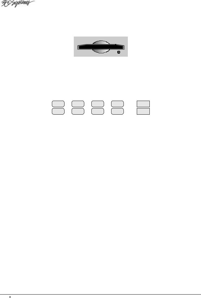
Transport Control Section
Although the TCR recorder shares no technical kinship with tape-based products, it is convenient to continue many of the operational traditions, such as the notion of a “tape transport”, referred to in this book as just “transport”. Other tape terminology, as in the words “rolling”, “punch-in”, “punch-out”, “rewind” and “varispeed”, are to be taken in the spirit of analog ancestry.
The Transport Control Section contains five buttons, used to control the delivery of audio in a VTR-like fashion:
PLAY |
|
STOP |
|
REC |
|
AUTO |
|
REVIEW |
|||||
|
|
|
|
|
|
|
|
|
|
|
|
|
|
|
|
|
|
|
|
|
|
|
|
|
|
|
|
Play
The Play button’s primary purpose is to initiate playback of a recorded file. In the TCR recorder, it can also operate in concert with other keys, or operating modes:
∙Press PLAY to play back any highlighted file on the Files Menu. The file will play from the Head Point to the Tail Point at normal speed.
∙While editing, press PLAY to play back a file from the cursor’s current position (that is, the value shown in the Time Code Display).
∙In the Loop Mode, press PLAY to repeat the file continuously.
∙Press PLAY + REC while the transport is rolling to punch-in to record mode.
∙While recording, press PLAY to punch-out of the record mode and keep rolling.
Stop
The STOP button will always stop all transport functions. When working with menus, press STOP to exit from the menu.
Record
Press REC + PLAY to start recording at the cursor’s current position.
From the File List, pressing REC + PLAY will create a new file in the current directory.
Auto-Record
The Auto-Record feature permits accurately pre-planned insert recordings to be made in an existing track. In practice, the user determines a punch-in point and a punch-out point. On pressing AUTO, the system will pre-roll, enter record at the Edit-In point, exit the record mode at the Edit-Out point, post-roll , and come to a stop.
Review
Similar to the “replay” mode in an editing system, the REVIEW key will place the TCR in an automatic review mode. The system will pre-roll and enter Play at the Edit-In point; playback continues through the Edit-Out point, and after a post-roll, the transport stops.
2-10 Overview |
TCR Series User's Manual |
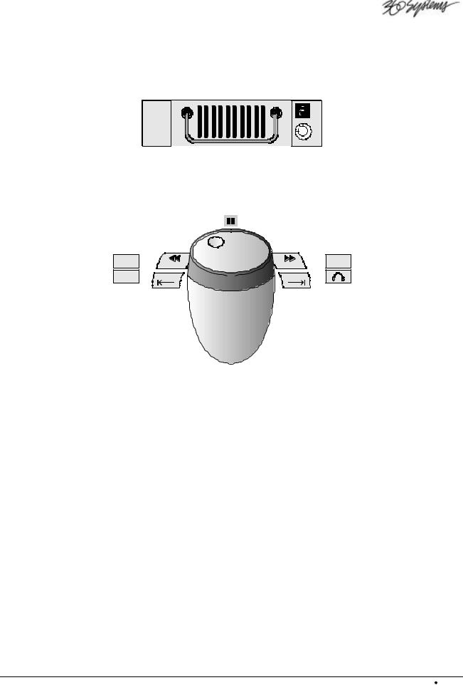
Drive Bay
The Drive Bay located below the control panel can house an optional hard disk drive, either as a fixed unit or installed in a removable drive carrier. When a drive carrier is installed, an illuminated digit above the drive lock indicates the drive’s numeric ID.
Jog Section
The Jog Section is used for transport control, and for making adjustments to other machine settings. As in the Keypad Section, many buttons have a dual-function.
ALT |
|
SHTL |
|
ADJ - |
ADJ + |
ADJUST |
EDIT IN |
EDIT OUT |
|
The Jog Wheel
The Jog Wheel in TCR is heavily weighted to provide a better tactile response than a light plastic knob. It combines the traditional video functions of Jog and Shuttle, and also the audio function of “Scrub” editing.
∙The Jog Wheel may be used to jog audio forward or backward at a variable speed, proportional to the rate at which the wheel is turned.
∙The wheel may be used in Shuttle Mode to play audio forward or backward, at a fixed speed proportional to the rotational position of the wheel. Play speeds up to 60x normal may be selected in Shuttle Mode.
∙Within Menus and Displays, the wheel may be used to scroll through a list of selections; to adjust a time code value; or to select alphabetic characters for text entry.
Pause LED
The PAUSE LED lights momentarily in both Jog and Shuttle modes when the transport is at zero speed.
TCR Series User's Manual |
Overview 2-11 |

Shuttle
Press SHUTTLE to change the function of the Jog Wheel from a jog control to a shuttle control. In this mode, rotate the Jog Wheel to shuttle the transport forward and backward at a speed proportional to the direction and position which the wheel is turned (up to 60x play).
ALT
The ALT button is provided for future enhancements.
Adjust
Many keys in the Jog Section change from transport controls to adjustment controls: On the Transport Screen, press ADJUST to display the Adjust Menu.
∙<< (Rewind) changes to ADJ-, which allows you to “nudge” a value down by one increment.
∙>> (Fast-forward) changes to ADJ+, which allows you to “nudge” a value up by one increment.
∙EDIT IN changes to , which allows you to move the Time Code Register’s underline to the left.
∙EDIT OUT changes to , which allows you to move the Time Code Register’s underline to the right.
The Jog Wheel changes to allow you to “dial in” values.
<</ Adjust -
∙Press << to rewind the transport at a fixed speed, ranging up to -60x play.
∙Press << twice to locate immediately to the next stop point earlier in time.
∙In “adjustment” mode, press ADJ- to “nudge” a value down by one increment.
>>/ Adjust +
∙Press >> to fast-forward the transport at a fixed speed, ranging up to +60x play.
∙Press >> twice to locate immediately to the next stop point later in time.
∙In “adjustment” mode, press ADJ+ to “nudge” a value up by one increment.
Edit In / 
The EDIT IN button is used in combination with other buttons to perform special functions, such as storing and recalling a time value related to an Edit-In location.
∙For example, press RECALL, EDIT IN to recall a stored Edit-In point.
∙Press STORE, EDIT IN to store the current Time Code Register value.
∙In “adjustment” mode, the  symbol will move the Time Code Register’s underline to the left.
2-12 Overview |
TCR Series User's Manual |

Edit Out /
The EDIT OUT button is used in combination with other buttons to perform certain special functions, such as storing and recalling a time value related to an Edit-Out location.
∙For example, press RECALL, EDIT OUT to recall a stored Edit-Out point.
∙Press STORE, EDIT OUT to store the current Time Code Register value.
∙In “adjustment” mode, the  symbol will move the Time Code Register’s underline to the right.
Headphones
The HEADPHONE button is used in combination with the Jog Wheel to select the desired volume. A Headphone Menu is appears, superimposed over the current display.
Power Switch
Use the POWER switch to turn power on or off.
Note The TCR can be powered off at any time from any screen. When power is restored, the system returns to the same non-menu screen that was active at powerdown. If TCR is recording during a power loss, all but the last few seconds of audio will be saved. If power is lost during an edit operation, the edit will not be saved.
TCR Series User's Manual |
Overview 2-13 |
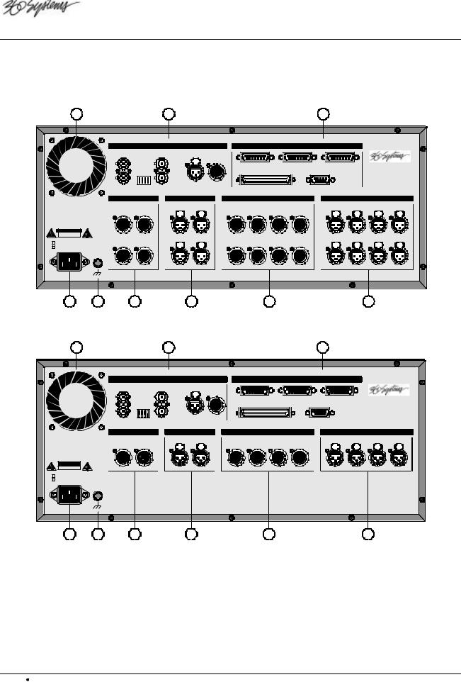
Rear Panel Description
The TCR4 and TCR8 rear panels are divided into sections as illustrated below. The sections are identical between the four and eight track models, except for the different number of connectors in the audio input and output sections.
|
1 |
|
|
|
4 |
|
|
|
|
|
5 |
|
|
|
|
SYNC AND TIME CODE |
|
|
|
CONTROL |
|
|
|
|
|
|
|||
|
WORD CLOCK |
|
|
LTC IN |
LTC OUT |
|
|
|
|
|
|
|
||
|
OUT IN |
0 WCLKTERM |
VITC TERM VIDEO TERM |
|
VITC |
|
|
|
|
|
|
|
|
|
|
|
IN |
|
|
CONTROL IN |
|
CONTROL OUT |
GPI/O |
|
|
|
|||
|
S4 |
VIDEO |
|
|
SCSI |
|
|
P2 |
|
|
|
|||
|
|
|
|
|
|
|
|
|
|
|||||
|
REF IN |
|
|
|
|
|
|
|
|
|
||||
|
|
I |
|
|
|
|
|
|
|
|
|
|
|
|
|
DIGITAL OUT |
|
DIGITAL IN |
|
ANALOG OUT |
|
|
ANALOG IN |
|
|
|
|||
|
|
|
|
|
1-2 |
3-4 |
|
|
|
|
1 |
2 |
3 |
4 |
|
|
1-2 |
3-4 |
|
|
|
1 |
2 |
3 |
4 |
||||
|
|
|
|
|
5-6 |
7-8 |
|
|
|
|
5 |
6 |
7 |
8 |
115 V~ |
50-60 Hz |
5-6 |
7-8 |
|
|
|
5 |
6 |
7 |
8 |
||||
230 V~ |
2.5 A MAX |
|
|
|
|
|
|
|
|
|
|
|
|
|
|
GND |
|
|
|
|
|
|
|
|
|
|
|
|
|
2 |
3 |
6 |
|
|
7 |
|
|
8 |
|
|
|
|
9 |
|
TCR8 Rear Panel Sections
|
1 |
|
4 |
|
5 |
|
|
SYNC AND TIME CODE |
|
CONTROL |
|
|
|
DIGITAL OUT |
DIGITAL IN |
ANALOG OUT |
ANALOG IN |
115 V~ |
50-60 Hz |
|
|
|
|
230 V~ |
2.5 A MAX |
|
|
|
|
|
GND |
|
|
|
|
2 |
3 |
6 |
7 |
8 |
9 |
TCR4 Rear Panel Sections
1) |
Exhaust Fan |
4) |
Sync and Time code Section |
7) |
Digital Audio Inputs |
2) |
AC Power |
5) |
Control Section |
8) |
Analog Audio Outputs |
3) |
Ground Post |
6) |
Digital Audio Outputs |
9) |
Analog Audio Inputs |
|
|
|
|
|
|
Following are more detailed descriptions of each rear panel section.
2-14 Overview |
TCR Series User's Manual |
 Loading...