


For use with Software Version 4.05.370
Image Server 2000 120
Image Server 2000 250
Image Server 2000 400
April 2008
Copyright 2008, 360 Systems
All rights reserved
Printed in the United States of America
900-105-0007-07 Image Server 2000 UM
Page 2 |
Image Server 2000 Owner’s Manual |

Contents
Contents______________________________________________________________ 3
Preface _______________________________________________________________ 8
Software and Operations Manual Revisions............................... |
8 |
Safety Notices _________________________________________________________ 9 |
|
Safety Terms and Symbols ........................................................ |
9 |
General Safety Caution............................................................. |
9 |
Personal Injury Precautions....................................................... |
9 |
Product Registration ................................................................ |
10 |
Product Improvements and Upgrades ...................................... |
10 |
Trademarks ............................................................................. |
10 |
Software Copyrights ................................................................ |
10 |
Video and Audio Copyright Reminder ..................................... |
10 |
Introduction _________________________________________________________ 11 |
|
Key Features and Benefits ........................................................ |
14 |
Applications for 360 Systems Image Servers ............................. |
15 |
Available Models .................................................................... |
16 |
Installation___________________________________________________________ 17 |
|
Unpacking .............................................................................. |
17 |
Rack Mounting........................................................................ |
18 |
Important Installation Notes..................................................... |
18 |
System Cooling ....................................................................... |
18 |
Power Conditioning ................................................................ |
19 |
About Image Server Software................................................... |
20 |
Image Server Hardware Interface _______________________________________ 21 |
|
Front Panel Features ................................................................ |
21 |
Power ON/OFF button ............................................................ |
21 |
Indicators................................................................................ |
21 |
Rear Panel Features ................................................................. |
23 |
Video Inputs ........................................................................... |
23 |
Video Outputs......................................................................... |
23 |
Audio I/O................................................................................ |
23 |
Analog/Digital Audio Selection................................................ |
24 |
Serial Control Ports.................................................................. |
24 |
Gigabit Ethernet Port ............................................................... |
25 |
GPI Control............................................................................. |
25 |
Genlock Sync Reference.......................................................... |
25 |
LTC Time Code Input .............................................................. |
25 |
Image Server 2000 Owner’s Manual |
Page 3 |

|
LTC Time Code Output ........................................................... |
26 |
|
Keyboard ................................................................................ |
26 |
|
Mouse .................................................................................... |
26 |
|
Monitor................................................................................... |
26 |
|
Power ..................................................................................... |
26 |
|
Basic Operations______________________________________________________ 27 |
|
|
The Image Server Desktop ....................................................... |
27 |
|
Launching the Graphic User Interface ...................................... |
27 |
|
Shutting Down Image Server ................................................... |
27 |
|
On-Screen Main Menu Bar ...................................................... |
28 |
|
System Menu Bar .................................................................... |
29 |
|
The Status Bar ......................................................................... |
30 |
|
The Transport Channel View ................................................... |
31 |
|
Transport Menu Bar................................................................. |
31 |
|
Playlist Menu Bar .................................................................... |
33 |
|
MAKING A RECORDING FROM THE GUI.............................. |
35 |
|
Record Configuration Options ................................................. |
35 |
|
Set Channel 1 to the Transport View ........................................ |
35 |
|
Setting the Sync Source ........................................................... |
35 |
|
Setting the Video Input Source................................................. |
36 |
|
Arming the Audio tracks .......................................................... |
37 |
|
Setting the Recording Format................................................... |
37 |
|
Setting the Time Code Source.................................................. |
38 |
|
Beginning Recording ............................................................... |
38 |
|
USING E-E Mode to Monitor the Recording Source .................. |
40 |
|
PLAYING A CLIP FROM THE GUI........................................... |
41 |
|
Beginning Playback................................................................. |
41 |
|
Looping a Clip ........................................................................ |
41 |
|
Pausing a Clip ......................................................................... |
41 |
|
Ejecting a Clip......................................................................... |
42 |
|
Using Jog ................................................................................ |
42 |
|
Using GO-TO ......................................................................... |
42 |
|
Using Fast Forward / Rewind ................................................... |
42 |
|
Using Shuttle to Control Playback Speed.................................. |
42 |
|
EDITING A CLIP ..................................................................... |
43 |
|
Using Edit-while-Recording ..................................................... |
43 |
|
SYSTEM CONFIGURATION.................................................... |
45 |
|
Assigning Names to the Server and Transport Channels............ |
45 |
|
Programming GPIO Outputs.................................................... |
46 |
|
Programming GPIO Inputs....................................................... |
47 |
|
Configuring Linear Time Code (LTC)........................................ |
48 |
|
Configuring the Network ......................................................... |
48 |
|
Setting the Date and Time ....................................................... |
50 |
|
Calibrating Channels ............................................................... |
51 |
|
CLIP NAVIGATOR .................................................................. |
52 |
|
Renaming and Deleting Clips .................................................. |
52 |
|
Sorting Clips ........................................................................... |
52 |
|
Filtering the Clip Display......................................................... |
52 |
|
Finding Clips........................................................................... |
53 |
Page 4 |
Image Server 2000 Owner’s Manual |
|

Finding Clips Using Wildcards................................................. |
53 |
Finding Clips Using Regular Expressions .................................. |
54 |
USING PLAYLISTS .................................................................. |
55 |
The Playlist view ..................................................................... |
56 |
Creating and Running a Playlist ............................................... |
57 |
Loading a Playlist (FILE>LOAD).............................................. |
58 |
Saving a new Playlist (FILE>SAVE AS)..................................... |
58 |
Saving an existing Playlist (FILE>SAVE)................................... |
58 |
Setting a Start Time for a Playlist .............................................. |
58 |
Stopping a Playlist (STOP) ....................................................... |
58 |
Pausing a Playlist (PLAY/PAUSE).............................................. |
59 |
Cueing a Clip (CUE) ................................................................ |
59 |
Looping a Playlist (LOOP [X]) ................................................. |
59 |
Showing the First Frame of a CUED clip (SHOW)..................... |
59 |
Preparing the Next Clip for Playback (NEXT)............................ |
59 |
Jumping to a selected Clip (JUMP) ........................................... |
59 |
Automatically scrolling to the currently playing Clip (HOME) ... |
59 |
Setting the Maximum Number of Played Items to Keep ............ |
60 |
Enabling As-Run Logging......................................................... |
60 |
Viewing, Editing and Archiving Playlists................................... |
60 |
EDITING PLAYLISTS ............................................................... |
61 |
Removing a Clip from a Playlist ............................................... |
61 |
Removing All Clips Above or Below the Selected Clip ............. |
61 |
Inserting a HOLD into a Playlist............................................... |
61 |
Appending a Playlist (FILE->APPEND) .................................... |
61 |
Changing the duration of Clips in a Playlist .............................. |
62 |
Mapping GPO to Playlist events .............................................. |
63 |
Mapping GPI to Control a Playlist............................................ |
64 |
Advanced Topics______________________________________________________ 65
System Timing......................................................................... |
65 |
Using Embedded Audio........................................................... |
66 |
Using Audio Sample Rate Conversion...................................... |
67 |
Using Channel Ganging .......................................................... |
68 |
Using the DV Video and Graphics Option ............................... |
69 |
Importing TARGA Graphics Files ............................................. |
70 |
Animation Import.................................................................... |
70 |
Still Frames ............................................................................. |
70 |
FTP File Transfers .................................................................... |
71 |
Network Time Protocol ________________________________________________ 75
Automatic Date/Time Updates................................................. |
75 |
Connecting to the Network...................................................... |
75 |
Configuring NTP ..................................................................... |
76 |
Selecting the Time Zone.......................................................... |
76 |
Entering Network Parameters................................................... |
77 |
Image Server 2000 Owner’s Manual |
Page 5 |

Automation Control ___________________________________________________ 79
Remote Serial Control ............................................................. |
79 |
Configuring the automation interface ....................................... |
80 |
Other Automation Options ...................................................... |
81 |
Tested Automation Controllers................................................. |
83 |
Tested Remote Control Panels and Switchers ........................... |
83 |
Remote Workstation Interface __________________________________________ 84
System Requirements .............................................................. |
85 |
About the Remote Workstation Interface .................................. |
85 |
Operations.............................................................................. |
85 |
Installation .............................................................................. |
86 |
After Installation...................................................................... |
86 |
Hard Disk Management________________________________________________ 88
About RAID 5 ......................................................................... |
88 |
Improved Write Performance................................................... |
89 |
Managing Disk Arrays ............................................................. |
89 |
Error Notification and Repair ................................................... |
89 |
Log-In to the RAID Utilities...................................................... |
91 |
Determining the Condition of the RAID Array .......................... |
92 |
Displaying the Alarm Log of the Raid Array.............................. |
93 |
Checking Status of the Drives .................................................. |
94 |
Removing the Degraded Drive from the RAID Unit .................. |
95 |
Rebuilding the RAID Array ...................................................... |
96 |
Replacing Hard Drives ............................................................ |
96 |
Maintenance _________________________________________________________ 97
Fault Diagnostics..................................................................... |
97 |
Front Panel Indicators.............................................................. |
97 |
Gigabit Ethernet Indicators....................................................... |
98 |
Access to Components ............................................................ |
98 |
Removing the Front Panel........................................................ |
98 |
Removing the Top Cover......................................................... |
98 |
General Handling Precautions ................................................. |
99 |
Installing/Removing I/O Cards ............................................... |
100 |
Accessing the Motherboard ................................................... |
100 |
Analog/Digital Audio Selection.............................................. |
101 |
Audio Level Calibration......................................................... |
102 |
Calibration Procedure............................................................ |
102 |
Program Updates via CD-ROM.............................................. |
104 |
Replacing a Hard Drive ......................................................... |
105 |
Factory Repair Policy............................................................. |
105 |
Regulatory Certifications........................................................ |
106 |
Safety.................................................................................... |
106 |
Laser Compliance.................................................................. |
106 |
Radio Interference Compliance.............................................. |
106 |
Product Warranty____________________________________________________ 108
End User License Agreement___________________________________________ 109
Page 6 |
Image Server 2000 Owner’s Manual |

Appendix A _________________________________________________________ 111
Connector Specifications ....................................................... |
111 |
Audio XLR-3 Connector Pinout.............................................. |
111 |
Serial Control Connector Pinout ............................................ |
111 |
BNC Connectors ................................................................... |
112 |
GPI Connector Pinout ........................................................... |
112 |
System Board Ports................................................................ |
114 |
Appendix B _________________________________________________________ 115
Serial Command Protocols..................................................... |
115 |
VDCP Command Table ......................................................... |
115 |
BVW Serial Command Table ................................................. |
117 |
Odetics® Protocol.................................................................. |
118 |
Appendix C _________________________________________________________ 121
Technical Specifications ........................................................ |
121 |
Keyboard Shortcuts ............................................................... |
123 |
APPENDIX D – PLAYLIST MANAGEMENT DETAIL _______________________ 124
APPENDIX E – AS-RUN LOGGING DETAIL______________________________ 127
As-Run Naming Convention .................................................. |
127 |
Sample As-Run Log ............................................................... |
127 |
As-Run Log Page Header ....................................................... |
127 |
As-Run Log Body................................................................... |
128 |
APPENDIX M – IMPORTING MPEG PROGRAM STREAM FILES ____________ 129
Encoding MPEG-2 Files Compatible with Image Server........... |
129 |
General Requirements........................................................... |
130 |
Appendix O _________________________________________________________ 131
Mechanical Drawing ............................................................. |
131 |
Index_______________________________________________________________ 132
Image Server 2000 Owner’s Manual |
Page 7 |

Preface
This manual provides installation, setup and operating instructions for 360 Systems’ Image Server™ 2000. It is organized to provide quick access to topics of primary interest. An extensive Table of Contents is provided at the beginning and a subject Index at the end, to assist in locating information.
If you have already used hard disk video servers (or VTRs), you may find discussion of the basic server to be covering familiar topics. However, it is strongly recommended that engineering managers and staff members operating the Image Server read through this manual. Being familiar with its operation can prevent operational mistakes, and will make all users aware of important setup and maintenance issues.
Software and Operations Manual Revisions
Software revisions are released from time-to-time that introduce new product features, or improve the performance of the product. When such revisions are shipped in the form of a CDROM, printed operational notes will be included. When revisions are introduced in the course of product production, an updated Operations Manual will be shipped with new servers.
The title page of an Operations Manual indicates its revision number, which should always match the software revision of the server with which it is used. Operations Manuals for the latest revision may be obtained from 360 Systems Customer Service, or from 360 Systems’ web site.
Your comments are welcome. If anything in this manual seems unclear, please let us know by sending an email to support@360systems.com.
Typographical Conventions
The following typographical conventions are used to clarify meaning:
•Connector or indicator labeling that appears on the unit is shown in Arial Narrow Bold.
•GUI menu items are shown in Arial Bold.
•Test typed into the GUI and Key Commands are shown in Courier Bold.
•GUI sub-menu paths are shown by the > symbol.
Page 8 |
Image Server 2000 Owner’s Manual |

Safety Notices
Safety Terms and Symbols
THE FOLLOWING WARNING SYMBOLS ARE USED IN THIS MANUAL:
ENGLISH |
ATTENTION: REFER TO OWNER’S MANUAL FOR IMPORTANT |
|
INFORMATION. |
FRANÇAIS |
ATTENTION: VEUILLEZ VOUS RÉFÉRER AU MODE D’EMPLOI |
|
POUR UNE INFORMATION IMPORTANTE. |
ITALIANO |
ATTENZIONE: FATE RIFERIMENTO AL MANUALE PER |
|
INFORMAZIONI IMPORTANTI. |
ESPAÑOL |
ATENTCION: FAVOR DE REFERIR AL MANUAL DE |
|
OPERACION POR INFORMACION IMPORTANTE. |
|
|
ENGLISH |
WARNING: ELECTRICAL SHOCK HAZARD. |
FRANÇAIS |
AVERTISSEMENT: DANGER DE CHOC ÉLECTRIQUE. |
ITALIANO |
AVVERTIMENTO: PERICOLO DI SHOCK ELETTRICO. |
ESPAÑOL |
ADVERTENSIA: PELIGRO DE CHOQUE ELECTRICO. |
General Safety Caution
•Heed the following important cautions regarding the Image Server in order to avoid personal injury or equipment damage.
•Only qualified personnel should perform installation and service. Refer to appropriate sections of this product manual for instruction. Contact 360 Systems Customer Support for further explanation, or to clarify any uncertainty.
•Disconnect the power cord before removing the cover.
Personal Injury Precautions
To avoid electric shock, do not operate this product with covers removed.
To avoid risk of fire, replace the power cord only with same type and rating as specified. Replace damaged power cords immediately.
This product is grounded through the grounding conductor of the power cord. To avoid electric shock, do not remove or modify the contacts on the plug.
Prevent the power cord from being walked on, pinched, or abraded.
To reduce the risk of fire or electric shock, do not expose this unit to rain or moisture. Remove jewelry, such as rings, watches, or necklaces before servicing this equipment.
Image Server 2000 Owner’s Manual |
Page 9 |

Product Damage Precautions
•Image Server recorders contain hard disk drives and other fragile electronic and mechanical devices. While this product is very reliable, it is still vulnerable to shock. Handle it with care, and exercise caution not to drop or bump the recorder as damage to internal components may result. Turn off power before moving the server.
•Do not obstruct air vents. Maintain an ambient temperature below 30°C (86°F).
•Clean only with a soft cloth dampened with water. Do not spray cleaners or solvents directly on the product.
 CAUTION:
Replace battery only with the same, or equivalent, battery type. Follow all local laws regarding the disposal of BR and CR Lithium batteries. Batteries should be fully discharged prior to disposal.
 CAUTION:
Never use the rear-panel power supply switch to shutdown the Image Server. Doing so may cause errors in the hard disk array. Should this happen, the array can be reinitialized without any data loss; however, the process may take several hours. Shutdown the system only by momentarily pressing the front panel power button, or through the On-Screen user interface.
Product Registration
Important: As the owner of new capital equipment, you will want to take advantage of product information, enhancements, upgrades, or notifications issued by 360 Systems. Send in your Warranty Card so 360 Systems can remain in contact with you. Mail or fax it to 360 Systems offices in the USA at the address given on page 105.
Product Improvements and Upgrades
360 Systems reserves the right to make changes and/or improvements to its products without incurring any obligation to incorporate such changes or improvements in units previously sold. Certain features mentioned in this document may not be present in all models. Image Servers are not offered for sale in all countries.
Trademarks
Image Server, Multi-Format Image Server, 360 Systems, 360 Systems Broadcast, Bit-for-Bit, and Direct Digital Import are trademarks or registered trademarks of 360 Systems in the U.S. and/or foreign countries. Other trademarks referred to in this document are the property of their respective owners.
Software Copyrights
Software in this product is based on the work of, or is copyright by, 360 Systems, SuSE® GmbH, Trolltech, and FreeType Team. Copyright 2003-2008 by 360 Systems.
Video and Audio Copyright Reminder
It is illegal to use this product to make copies of copyrighted material without the express permission of the copyright holder
Page 10 |
Image Server 2000 Owner’s Manual |
Introduction
360 Systems’ Image Server™ 2000 is a multi-channel video recorder/server designed for television broadcast and production applications. It can play three independent video streams at once, and store up to 170 hours of MPEG-2 video, with four audio channels per video stream. It occupies just 3½” of rack space. The server’s extensive feature set makes it an excellent choice for VTR replacement, broadcast automation, remote trucks; production for PEG, corporate and house- of-worship video; and live entertainment presentations. Image Server 2000 is produced in separate NTSC and PAL models. References in this document to frame counts other than 29.97 or 30 frames should be understood as a PAL example.
The Transition to a Digital Plant
Image Server 2000 smoothes the transition to digital production and broadcasting by providing both composite video and serial digital (SDI) interfaces, plus program file transfers over Gigabit Ethernet. It’s never necessary to add outboard video A/D or D/A converters or MPEG encoders; premium-quality codecs are included as standard equipment. The server’s dual analog and digital personality—for both video and audio—makes it fit seamlessly into an existing analog facility, or become part of a new digital build-out. Apart from serving its intended purposes, Image Server 2000 is also valuable for its ability to convert between different analog and digital media formats in real-time.
Exceptional Storage Capacity
The Image Server’s program storage is scaleable to suit the needs of both small and large users. It houses four hard drives within its compact enclosure, providing 52, 112 or 170 hours of storage at 12 Mb/sec. Storage time is proportional at other data rates. The server’s RAID-5 disk array provides a high level of security for stored programs. By spreading parity information across all drives, the RAID array helps keep the server in service—even with a failed drive. The multidrive storage array also generates the high data rates needed for multiple video streams at up to 50 Mb/sec, and enables fast program transfers through the Gigabit Ethernet port.
Drive Size |
Array Size |
Time @ 12 Mb/s |
Time @ 8 Mb/s |
|
(4 drives) |
2 audio channels |
2 audio channels |
||
|
||||
120 GB |
480 GB |
52 hours |
70 hours |
|
|
|
|
|
|
250 GB |
1.0 TB |
112 hours |
150 hours |
|
|
|
|
|
|
400 GB |
1.6 TB |
170 hours |
250 hours |
|
|
|
|
|
IMAGE SERVER 2000 STORAGE TIMES
The Image Server’s unique ability to play two video streams while recording a third, and at the same time do file transfers over Gigabit Ethernet, make it far more than just a VTR replacement.
Image Servers Support Traditional VTR Functions
The Image Server is a perfect drop-in replacement for popular VTRs. It saves costs for tape, machine maintenance, cassette prep, and storage. Its three output channels perform any combination of tasks, including responding to GUI or automation commands, clip trimming or browsing.
Image Server 2000 Owner’s Manual |
Page 11 |

Unlike a VTR, the Image Server can simultaneously record and play a program. A new recording can start at any time, even when two simultaneous playbacks are in progress. As a VTR replacement, the Image Server is controlled through a 9-pin serial interface. Several serial protocols are supported, allowing the Image Server to immediately operate with the controllers you already own. VDCP and Odetics protocols provide very complete server control, including editing functions. Sony BVW protocol is also provided in an abbreviated form allowing basic machine control, without insert-editing. Six parallel “GPI” control channels are also provided.
Compatibility with Automation Controllers
Image Servers work with automation controllers from many different manufacturers. They use established VDCP and Odetics protocols allowing 9-pin control of each server channel, for maximum flexibility. 360 Systems’ automation partners provide controllers for applications ranging from affordable systems for Pro-AV, up to large-scale broadcast solutions. Contact a 360 Systems application engineer, or an automation provider for assistance with your requirements.
Remote Controls
Hardware accessories are available from third-party manufacturers to perform transport control, trimming, clip replay and playlisting (automation). A table of approved controllers is provided elsewhere in this manual. Contact 360 Systems Sales Support team for assistance with a specific application.
The Image Server provides six GPI inputs for remote play, stop, and record capability from push-button panels or other GPI-controlled equipment. Six outputs are also provided; these may be used for command acknowledgement (to drive LEDs or logic inputs), or may output commands embedded within an Advanced Playlist on the Image Server.
Extended Feature Set
Image Server 2000 encodes video in MPEG-2 format, in 4:2:2 Profile with data rates to 50 Mb/sec, or in Main Profile to 15 Mb/sec. Both I-frame and long-GOP formats are supported. MPEG-2 file transfers in MXF-format are compatible with servers from other market leaders. Image Server 2000 can also receive IMX (D-10) files in the MXF format from Sony EVTRs.
The optional DV and Graphics capability allows Direct Digital Import™ of DV-25 and TARGA files to an Image Server over an Ethernet connection. DV files may then be trimmed, playlisted, stored, played out, and re-exported over Ethernet. They remain in DV format at all times, and are not converted to MPEG. TARGA files may be imported to the Image Server, and will be converted into separate high-resolution MPEG-2 “key” and “fill” files. These can be played as a synchronized pair, for downstream compositing.
Audio Features
Image Servers include both analog and digital audio circuits, making it an easy fit when upgrading a facility. Gold XLR connectors are used for audio inputs and outputs. Each output can be configured for either AES/EBU digital or +4 dBu balanced analog. In discrete digital format, each video program can have four channels of audio, whereas analog I/O provides two channels. (An AES/EBU line on a single XLR connector carries two audio channels, so a given number of XLR connectors make more channels possible in digital format). SDI embedded audio is also included as standard equipment.
Page 12 |
Image Server 2000 Owner’s Manual |

360 Systems brings extensive experience in broadcast and pro-audio to the design of Image Servers. They employ a 24-bit word, and deliver a 20 dB improvement in SNR (10 times!) compared with older 16-bit audio systems. A sample-rate converter is included in the audio input, which may be inserted from the GUI. Input circuits provide excellent hum and RF rejection, and 20 dB of headroom. 360 Systems’ Bit-for-Bit® design strategy assures that Dolby®-E, Dolby AC3, or other forms of encoded audio will be stored and played correctly.
On-Screen Graphic User Interface
The Image Server’s On-Screen graphic user interface (GUI) gives fast access to all server functions. It is controlled by a standard keyboard and mouse (supplied) and requires only a VESAcompliant SVGA display.
The GUI displays a complete control panel for each server channel; these include transport control, clip file management and head and tail trimming. The GUI allows an Image Server to operate as three self-contained VTR equivalents.
System configuration is clear and straightforward with the GUI. It provides access to MPEG-2 encoding parameters, audio channel and time-code settings. Whenever new server features are installed (using the built-in CD-ROM drive) new set-up parameters and user-interface features become immediately available.
Remote Workstation Software allows the GUI to be remotely operated from a common Windows® PC connected by Ethernet. Separate work areas can be easily created within a building for ingest, trimming, playlisting, system monitoring or play-to-air.
File Transfers over Gigabit Ethernet
Image Servers go beyond providing just base-band connections for video and audio. Both DV and MPEG-2 file transfers over Gigabit Ethernet open the door to new IP solutions for transferring video across the room—or across the country—at high speed and low cost.
By adding economical Ethernet switches and broadband connections, the Image Server’s design enables low-cost networking of broadcast operations from ingest to storage, for editing, play-to-air and archiving. The Image Server moves programs many times faster than real time, saving time and streamlining operations.
360 Systems’ MXF implementation for MPEG-2 transfers uses Operational Patterns 1a and 1b. It has been tested for compatibility with MXF files from many other manufacturers. 360 Systems can make Image Server MXF files available for testing and evaluation through our FTP site. Contact the customer service department to arrange for access.
Reliability Counts
360 Systems has 34 years experience manufacturing equipment for television broadcast and other industries that require elevated reliability. We understand quality and reliability, and have given close attention to design issues like power, cooling, and protecting stored data.
Image Server 2000 Owner’s Manual |
Page 13 |

Key Features and Benefits
Image Server 2000 is designed from the ground up to deliver outstanding performance and value in a multi-channel MPEG-2 and DV-format server. Three video outputs with analog, digital, and Gigabit Ethernet interfaces make it an excellent choice for the next-generation plant.
•MPEG-2: Main Profile @ Main Level and 4:2:2 Profile @ Main Level to 50 Mb/s.
•Internal RAID-5 storage configurable to 170 hours
•Three simultaneous video outputs, or 1 video input and two outputs
•SDI and composite video inputs and outputs
•Balanced analog and AES/EBU digital audio ports
•Four audio channels (2 AES stereo pairs) for each video channel
•Embedded audio option available.
•Serial control via VDCP, Sony BVW or Odetics protocols
•Compatible with leading broadcast automation systems
•Fast FTP transfers on Gigabit Ethernet
•VITC time code
•LTC Time code input and output; VITC written and read
•Accurate head and tail trimming
•Advanced Playlisting: Build, edit, store, playback, and loop multiple lists
•Looping
•Closed-Captions
•Keyboard shortcuts for editing
•Set-up, administration and control via graphic user interface
•Remote Workstation Software for Windows computers available
•31-character file names
•Compact 2RU (3½”) [88mm] enclosure, low power consumption
•Low cost
With the DV+Graphics Option:
•Import and playout of DV video and TARGA graphics
•Drag-and-Drop DV transfers from popular desktop editing programs
Page 14 |
Image Server 2000 Owner’s Manual |

Applications for 360 Systems Image Servers
Image Servers add value to many applications in broadcasting, cable distribution, video production, Pro A/V, entertainment and sports venues. Many of these tasks are impractical with videotape. In contrast, an Image Server provides immediate record and playback of any source, and lends a spontaneous appearance to broadcasts, presentations and live events.
•News Production – Promos, teasers, intros, news segments, graphics, animation
•Graphics Server – Play paired files for use in key-and-fill applications
•Master Control – Program and commercial playout, station IDs, promos, teasers
•Program Ingest – Automated capture of satellite, tape, microwave, and fiber feeds
•FTP File Delivery – Deliver news, promos, spots over DSL or ATM lines
•Play-to-Air Server – Playback under automation control
•Program Store-and-Forward – Temporary storage for subsequent delivery
•Commercial Insertion – Playout under automation control
•Instant Replay – Hot Key playback of sports plays, news clips, stills, and graphics
•Sports Shows and Events – Player bios, animations, graphics, promos
•Game Shows – Prizes, graphics, animations, promos
•Talk and Variety Shows – Promos, teasers, intros, outros, graphics, animations
•Award Shows – Nominees, categories, promos, graphics, animations
•Theme Parks and Casinos – Playout for show backgrounds, event lists, kiosks
•Houses of Worship -- Projection displays, program production, broadcasting
•Colleges and Universities – On-campus networks, production, presentations
•Digital Signage – drive projectors, flat-panel displays, kiosks
•Entertainment Industry – Road show displays, projection
•City Governments, Public Access – Long recording times, high quality video
•MidMarket Broadcast– High performance at an attractive price
Image Server 2000 Owner’s Manual |
Page 15 |

Available Models
Image Server 2000 Model 120
Provides 52 hours of storage at 12 Mb/sec.
Image Server 2000 Model 250
Provides 112 hours of storage at 12 Mb/sec.
Image Server 2000 Model 400
As above, with 170 hours of storage at 12 Mb/sec
Storage Upgrades
Upgrades an Image Server 2000 to 170 hours of storage (at 12 Mb/sec). Field installable.
PAL Models
Add suffix PAL to model number when ordering. Specify mains cord required.
Available Options
•DV+Graphics
•Remote Workstation
•Embedded Audio.
Maintenance Spares
360 Systems is committed to keeping your Image Server on air. The server contains hard disk drives and other fragile electronic devices; and while it is designed to be very reliable, having spare parts on hand in the event of a fault is a good practice. Hard disk spares are particularly important. Please consider these important options at the time of your purchase, or shortly after.
•120 GB Image Server Hard Drive for 52 hour servers
•250 GB Image Server Hard Drive for 112 hour servers
•400 GB Image Server Hard Drive for 170 hour servers
•Image Server Power Supply, universal line voltage
Page 16 |
Image Server 2000 Owner’s Manual |

Installation
Unpacking
Your Image Server has been carefully inspected and calibrated before shipment to allow immediate operation upon installation. Check all items for signs of visible damage which may have occurred during shipment. If any item is damaged, contact the carrier to file a claim.
Keep the packing materials in the event that a unit must be shipped by you. If the original packaging is not available, make sure that the following criteria are met:
•Packaging must be able to withstand the product weight.
•Product must be held firmly within the package.
•There must be at least two inches (50mm) of space between the product and outer container.
•The corners of the product must be protected.
Package Contents
Confirm that all items on the packing list have been received. Contact 360 Systems if any item is missing.
Image Server 2000
Keyboard
2-Button Scroll Mouse.
Software CD-ROM backup copy
Remote Workstation Software CD
Rack Mount Hardware Kit
Operations Manual
Power cord
Warranty Card
The Image Server is not shipped with a video monitor. Select a VESA-compliant CRT or LCD monitor with a minimum refresh rate of 75 Hz. Note that the Image Server may not start correctly if an unsuitable monitor is connected.
If you own more than one Image Server, it may be appropriate to use a single keyboard, monitor, and mouse with a KVM switch to select between servers. Not all KVM switching systems are compatible. The KVM switch must supply an active signal to the Image Server at all times, even when switched away from it. When first powering up the Image Server, use only the supplied keyboard and mouse directly connected. Then test the KVM switch system that will be used thoroughly before installation is completed. NOTE: If the mouse and keyboard connections are interchanged, the Image Server may not boot up properly. Be especially careful about this when using extender cables.
Image Server 2000 Owner’s Manual |
Page 17 |

Rack Mounting
Note: If you plan to use digital audio, be sure to change the configuration of the Analog/Digital Audio Jumpers inside the unit before mounting the Image Server in a rack. The jumpers are factory set to the Analog audio position. For more information about changing the jumpers, see Analog/Digital Audio Selection on page 101.
There are four adhesive-backed rubber feet on the Image Server. These may need to be removed when rack mounting the unit.
In North America, the Image Server will usually be mounted in a 19” rack enclosure having 10-24 or 10-32 tapped holes. In countries with metric standards, the user will need to supply appropriate fasteners.
Cables attached to the rear of the Image Server should be supported by the rack mounting rails. Do not support substantial cable weight from the Image Server.
Remove the front panel to expose the rack screw slots. Fasten the Image Server into the rack using #10 flat-head Phillips screws (provided in North America). Replace the front panel. Tighten the front panel access screws.
Important Installation Notes
System Cooling
When many pieces of equipment are mounted in an equipment rack, a considerable amount of heat may be produced, which must be removed efficiently. Further, a lower operating temperature will make equipment operate more reliably, and it will last longer. In the extreme case, excessive temperatures cause rapid equipment failure, and damage which can be difficult to repair.
Heat in an equipment rack should be removed by forced air. This is often accomplished by blowers installed in the top of the rack, venting into the room. An alternative is to draw hot air from the top of the rack into an air-conditioning return duct, and not vent it into the equipment room; cold air should be ducted into the bottom of the rack.
The optimum air temperature for cooling electronic equipment is 25° C (72° F). When many pieces of equipment are contributing to the heat load, a substantial air-flow will be needed, and the inlet temperature may need to be lower.
Check These Points
•Are all ventilation holes in the Image Server free of obstruction?
•Can blowers or HVAC system adequately remove heat from the equipment rack?
•Have you measured the actual temperature inside the rack? Do this near the top.
•Verify that the HVAC system is not on a timer that can shut off on weekends or holidays.
•What procedures are in place to protect the equipment when the HVAC system fails?
Page 18 |
Image Server 2000 Owner’s Manual |

Important Installation Notes
Power Conditioning
It is good practice to operate an on-air video server from an Uninterruptible Power Source, or UPS. All utility power systems experience occasional transient events, including brownouts and dropouts, which are capable of taking a server off the air. It is the station operator’s job to plan for and overcome such contingencies.
UPS units suitable for smoothing short-term power line problems come in two varieties:
Change-over UPS Design
This design senses drop-outs and low-line voltage, and switches its output to an internal inverter operating from a battery. This UPS is low in cost, and is most often used in non-critical applications such as desk-top computers. A disadvantage is that it may create its own power transients when switching between utility power and its inverter supply. . For this reason
360 Systems does not recommend this type for use with Image Server.
Continuous Conversion UPS Design
This improved design continuously converts utility power to DC, stores it in a battery, then produces isolated AC power from an inverter. It never switches, and is immune to input transients, brownouts, and blackouts. Models are available with batteries of almost any size, making the continuous-conversion UPS suitable for transient suppression or long-term operating power in the absence of utility power.
Recommended UPS Models
The following makes of continuous conversion UPS systems are suitable for use with 360 Systems’ Image Server products:
APC Smart-UPS 2200-XL
Eaton/Powerware Corporation, Model 9125, www.powerware.com
This unit is available in several different configurations to accommodate various current load and power failure support times.
The minimum requirement for maximum current load for a single Image Server 2000 is 2 amps.
Operating Environment
A video server is the most critical element in a broadcast operation. Its installation should safeguard it from every external event that can interfere with it doing the task expected of it. 360 Systems’ engineers have experience with thousands of installations, and have become aware of a number of environmental factors that can adversely affect performance. Two of these have already been discussed: power conditioning and inadequate cooling. Two others, less obvious, should also be considered:
Image Server 2000 Owner’s Manual |
Page 19 |

Important Installation Notes
RF Interference by Cel Phones
Many people are not aware that cel phones can attain a very substantial power output, even when no conversation is taking place. You may have experienced the effect of a cel phone interfering with a common desk phone placed nearby. Carrying a cel phone into a machine room where it is in close proximity to broadcast equipment and its associated wiring is unwise. They are able to interfere with serial control commands, video synchronization, and in some cases can crash the CPU in equipment.
Some major broadcasters prohibit the carrying of cel phones into certain machine areas. 360 Systems believes that the risk of undesired equipment behavior from their RF fields is very real.
Static Discharge
Static electricity discharge is accepted by most people as an inevitable consequence of living in a dry area. It is, rather, a result of floor coverings that may enhance appearances, but are inappropriate for use around critical pieces of broadcast equipment. Static discharge can do two adverse things:
•Discharge into a connector can—and will—destroy internal circuitry of equipment. The result will always be difficult to diagnose and repair.
•Discharge to equipment frames or wiring can crash a CPU and take the station off the air. The event may seem random or unrelated to static, but it is clearly a catastrophic event—and one that can repeat indefinitely as humidity varies.
Several steps can be taken to protect equipment from static discharge:
•Do not install critical broadcast equipment (video servers) in a room with carpeting.
•Connect equipment racks directly to an earth ground with a heavy copper conductor.
•Do not operate equipment with a lifted safety ground (green frame ground).
•Install a humidifier to reduce the level of static discharge.
About Image Server Software
The Image Server is shipped with its application programs and operating system installed.
The first time that it is started, it must be connected to a keyboard, monitor and mouse. The Image Server will ask you to accept the Software Licensing Agreement before it will operate. This screen will only appear during the initial startup.
The CD-ROM drive is intended only for installing software. It may not be used to load video or audio program content.
If for any reason it becomes necessary to reinstall any software, refer to the Maintenance chapter for instructions.
Page 20 |
Image Server 2000 Owner’s Manual |
Image Server Hardware Interface
Front Panel Features
Power ON/OFF button
The blue front panel button initiates start-up and shut-down of the Image Server. Press it momentarily to start the server. A sequence of start-up screens will appear, ending with the 3- channel graphic user interface.
When the Image Server is running, pressing the blue button momentarily will cause the system to begin an orderly shutdown.
In the event that the power does not turn off automatically after 30 seconds, hold the front panel power switch for 4 seconds.
In the event that the system has stopped responding to commands and will not shutdown, hold the button in for 4 seconds to force a power down.
Do not use the rear panel switch on the power supply to shut down the Image Server. Abrupt power loss can cause loss of information stored on the disk array. The rear panel power switch can be used to prevent re-application of power during service procedures once the normal shut down sequence is complete.
Indicators
Five blue LED Status Indicators appear on the front panel. The POWER, FANS, DRIVES and SYSTEM indicators are illuminated continuously when the system is functioning normally. GENLOCK will be off when Internal Sync is selected, and illuminated when Genlock is selected. See the table Front Panel Indicators on page 97 for diagnostic meanings.
Image Server 2000 Owner’s Manual |
Page 21 |
Rear Panel Drawing
|
1 |
|
|
|
|
2 |
|
|
3 |
|
|
4 |
|
5 |
|
6 |
|
|
|
|
|
|
OUTPUT |
|
|
INPUT |
|
|
|
|
|
|
|
|
|
|
MAIN 3 L |
MAIN 3 R |
MAIN 2 L |
MAIN 2 R |
MAIN 1 L |
MAIN 1 R |
MAIN IN L |
MAIN IN R |
ANALOG |
|
|
|
|
|
|
|
1 CH |
MAIN 3 L/R |
AUX 3 L/R |
MAIN 2 L/R |
AUX 2 L/R |
MAIN 1 L/R |
AUX 1 L/R |
MAIN IN L/R |
AUX IN L/R |
DIGITAL |
|
|
|
|
|
CH |
CH |
|
|
|
|
|
|
|
|
|
|
|
|
|
|
|
PLAY 3 |
PLAY 2 |
REC/PLAY |
|
|
|
|
|
|
|
|
|
|
|
|
|
|
100 - 240 VOLTS, 50 - 60Hz, 2 AMPS MAX |
|
|
|
|
|
|
|
|
|
LTC IN |
CVBS |
CVBS |
CVBS |
CVBS |
||
|
|
|
|
|
|
|
GPI |
|
|
|
|
CH 1-3 |
3OUT |
2OUT |
1OUT |
1IN |
|
|
|
|
|
|
|
|
|
|
|
|
GENLOCK |
|
|
|
|
|
|
|
|
MOUSE |
|
|
|
|
|
|
|
INPUT |
|
|
|
|
|
|
|
|
|
|
USB |
|
|
NET 1 |
NET 2 |
|
|
|
|
|
|
|
|
|
|
|
|
|
|
|
|
|
|
|
|
|
||
|
|
|
|
|
|
|
SERIAL |
MONITOR |
GIGABIT LAN |
GIGABIT LAN |
LTC OUT |
SDI |
SDI |
SDI |
SDI |
|
|
|
|
|
|
|
|
|
|
|
|||||||
|
|
|
|
|
|
|
|
|
|
|
|
CH 1-3 |
3OUT |
2OUT |
1OUT |
1IN |
|
|
|
|
KEYBD |
|
|
|
|
|
|
|
|
|
|
|
|
|
|
|
|
|
|
|
|
|
|
|
|
|
|
MADE IN USA |
|
|
|
|
|
|
|
|
|
|
|
|
|
|
|
|
WESTLAKE VILLAGE, CALIFORNIA, USA |
||
|
|
7 |
8 |
|
9 |
|
11 |
12 |
13 |
14 |
15 |
|
16 |
|
17 |
|
|
|
|
|
|
10 |
|
|
|
|
|
|
|
|
|
|
|
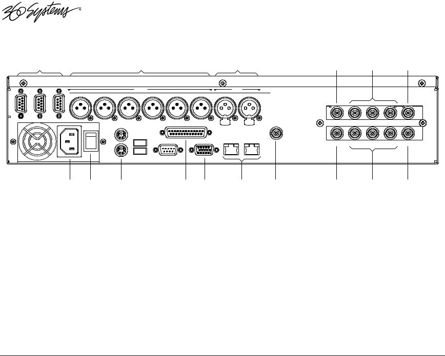
Figure 1: Rear Panel Features
1.(3) serial control ports (EIA-422)
2.(6) XLR-3 audio outputs (AES/EBU digital or +4 balanced analog)
3.(2) XLR-3 audio inputs (AES/EBU digital or +4 balanced analog)
4.LTC time code input
5.(3) Composite video outputs
6.Composite video input
7.AC Power connector
8.AC Power switch
9.Mouse port
10.Keyboard port
11.GPI port, 25-pin female:
(6) opto-isolated inputs, (6) status outputs
12.SVGA monitor port
13.Gigabit Ethernet ports
14.Genlock Input
15.LTC time code output
16.(3) SDI video outputs
17.SDI video input
Page 22 |
Image Server 2000 Owner’s Manual |

Rear Panel Features
Video Inputs
The Image Server records video on channel #1. It has separate BNC inputs for SDI (serial digital per SMPTE 259M) and analog video (CVBS) signals. Both video inputs have a fixed 75ohm termination. The graphic user interface selects between the two. Encoding is performed in MPEG-2 format within the server.
Video Outputs
Video outputs are provided in SDI and Composite (CVBS) formats simultaneously. Digital video appears in SDI format at 270 Mb/s and conforms to SMPTE 259M. Analog video is composite (CVBS).
Audio I/O
The Image Server provides audio inputs and outputs in three formats:
•Balanced analog audio at a reference level of +4 dBu.
•Digital audio in AES/EBU format per AES-3-2000.
•SDI embedded audio, 4-channels
These multiple standards facilitate the transition from an analog studio to digital production and broadcasting, and ensure that the server can operate with most equipment. Note that both analog and AES/EBU audio signals are not available at the same time on a given input or output. Internal jumpers select between analog or digital; however, each pair of inputs and outputs can be set up differently, if desired. A set of XLR-3 connectors allows high-quality connections to be made in either format. Embedded audio appears in the SDI output stream at all times.
Analog Audio Capability
When the analog audio input format is selected, each video channel has two audio channels, recorded together as a stereo pair. Internal trimmers allow adjustment to unity gain.
Digital Audio Capability
When AES/EBU digital audio is selected, each video channel has four audio channels, which are recorded as two stereo pairs. Because a single XLR connector carries a stereo pair in AES/EBU format, and only one (monaural) channel in analog, the server provides an extra pair of audio channels when used with AES/EBU audio signals.
Embedded Audio Capability
When SDI embedded audio is selected, four audio channels are available for recording. Embedded audio is always inserted in the video outputs. Note that discrete audio (analog or AES/EBU) is also available on XLR connectors, at the same time embedded audio appears in the video stream. Embedded audio has a 20-bit resolution.
Image Server 2000 Owner’s Manual |
Page 23 |

Audio Word Size and Sample Rate
The Image Server employs 24-bit audio A/D and D/A converters, and records audio into a 24bit frame, regardless of the word size received. The sample rate is fixed at 48K. When using the AES/EBU digital input, the 48K sample rate of the incoming digital audio must be derived from the video genlock reference. If it is not, or if a different sample rate is used, the Image Server’s input sample rate converters must be selected.
Encoded audio streams such as Dolby E® must be referenced to the video genlock, and the input sample rate converters must be disabled when recording such streams.
Analog/Digital Audio Selection
The following drawing illustrates jumper positions to select between analog or digital audio. Note that each output may be individually selected. As described earlier, when analog audio is selected, only two channels are available, while selection of AES/EBU digital audio provides two stereo pairs, one on each XLR connector. Both jumpers for each channel (Left & Right, or Main & Aux) must be set together, either analog or digital. The Image Server must be power cycled for jumper changes to take effect. For more detail, see Analog/Digital Audio Selection in the Maintenance chapter.
GAIN ADJUST |
|
|
JUMPER BLOCK PAIR SHOWN |
||||||||||||||||||||
|
|
|
|
|
|
|
|
|
|
|
|
|
|
|
|
IN DIGITAL POSITION |
|||||||
|
|
|
|
|
|
|
|
|
|
|
|
|
|
|
|
|
|
|
|
|
|
|
|
|
|
|
|
|
|
|
|
|
|
|
|
|
|
|
|
|
|
|
|
|
|
|
|
|
|
|
|
|
|
|
|
|
|
|
|
|
|
|
|
|
|
|
|
|
|
|
|
|
|
|
|
|
|
|
|
|
|
|
|
|
|
|
|
|
|
|
|
|
|
|
|
|
|
|
|
|
|
|
|
|
|
|
|
|
|
|
|
|
|
|
|
|
|
|
|
|
|
|
|
|
|
|
|
|
|
|
|
|
|
|
|
|
|
|
|
|
|
|
|
|
|
|
|
|
|
|
|
|
|
|
|
|
|
|
|
|
|
|
|
|
|
|
|
|
|
|
|
|
|
|
|
|
|
|
|
|
|
|
|
|
|
|
|
|
|
|
|
DIGITAL
ANALOG
JUMPER BLOCK PAIR SHOWN
IN ANALOG POSITION
Figure 1: Jumper location on audio card for selection of analog or digital audio.
Serial Control Ports
Each of the Image Server’s three 9-pin “D” connectors permits independent control of any of the three video channels. They can accept serial commands in VDCP, Sony BVW or Odetics protocol. The multiple serial ports allow simultaneous connection of an automation controller and a desktop controller. See the chapter on Automation Control for further details.
Most broadcast automation systems, and some remote control panels, employ the VDCP protocol. A list of supported VDCP commands will be found in Appendix B.
Many controllers used for transport, instant replay, and edit control employ Sony BVW or Odetics protocol.
Page 24 |
Image Server 2000 Owner’s Manual |

Gigabit Ethernet Port
Gigabit Ethernet ports are provided on the Image Server. The NET 1 port is intended for external transfer of program content between video servers. The server supports MXF file transfer (MPEG-2, Op 1a and 1b), which allows content interchange between products from different manufacturers, as well as file import in various formats from desktop editors.
The NET 2 port is reserved for future use and is not active. Use only the NET 1 port.
GPI Control
The Image Server provides six GPI inputs for control of machine functions, which appear on the 25-pin GPI connector. This “General Purpose Interface” can be connected to switch contacts or an open-collector transistor output. GPI inputs are programmable, and can provide machine control such as PLAY, STOP, or RECORD through simple external switches.
The Image Server also provides six GPI status outputs which may be used to confirm that a command has been received, or for other purposes. The functions of these open-collector outputs are programmable, and may be used to operate an LED, or they can be connected to a suitable logic input. The pin-out for the GPI connector will be found in Connector Specifications.
Genlock Sync Reference
A BNC connector is provided on the rear panel to receive a genlock signal. During normal operation, the Image Server should be referenced to an external genlock reference in the form of CVBS black. As with all video systems, this server and equipment connected to it must be referenced to a common genlock source. The GENLOCK input provides a fixed 75-ohm termination.
An internal crystal reference is also provided so that the server can be used as a stand-alone player, and also for convenience in performing tests in the laboratory. Use particular care when operating the server with an internal reference, as synchronization with other equipment is not possible.
Genlock Signal Quality
A genlock signal connected to the Image Server must conform to the RS-170A standard. PLL circuits used within the server remove residual jitter from the genlock signal. This may preclude the use of low-cost VCRs as signal sources, as they may introduce time instability (wow) into their output, making them inaccurate as a genlock source.
LTC Time Code Input
A LTC time code input is provided on the LTC IN BNC connector. This input may be selected by means of the On-Screen user interface and recorded as a time code reference. The LTC input provides a >10k ohm termination.
Image Server 2000 Owner’s Manual |
Page 25 |

LTC Time Code Output
An LTC time code output is provided on the LTC OUT BNC connector. It may be selected by means of the On-Screen user interface to output time code from any of the three video channels during playback. The LTC output has a source impedance of <5 ohms.
Keyboard
Attach the alphanumeric keyboard to the purple 5-pin KEYBD connector to control the server and manage clips with the On-Screen graphic user interface. Note that the server will only recognize the keyboard if it is attached before power up.
Mouse
A two-button scroll mouse is provided with the Image Server. Plug the mouse into the green 5- pin MOUSE port. Do not use the USB ports, even if the supplied mouse is USB capable. Note that the server will only recognize the mouse if it is attached before power up.
Monitor
A VESA-compliant computer monitor may be connected to the 15-pin VGA video port. The Image Server resolution is fixed at 1024 x 768 pixels, with a refresh rate of 72 Hz. This is bestviewed on 17-inch or larger monitors. 360 Systems does not provide monitors for the server. Note: Do not use older monitors that are not VESA compliant. The server may not start properly if an unsuitable monitor is connected.
Serial Port
The system board serial port is not used. Make no connection.
USB Ports
The system board USB ports are not used. Make no connection.
Power
An IEC mains socket is provided on the rear panel for power input. The Image Server will accept world-wide power sources in the range of 100-240 volts AC, 50-60 Hz. The server is shipped with a power cord appropriate for the region in which it is sold. Replace the power cord only with one of the same type and rating.
DO NOT use the power supply switch to shutdown the Image Server. Shutdown the system only by momentarily pressing the front panel power button, or through the HALT command on the On-Screen user interface. The rear panel power switch should only be used if the Image Server fails to shutdown after holding the front panel power switch for 4 seconds. The rear panel power switch can be used to prevent the application of power during service procedures once the normal shutdown sequence has completed.
The server may also be shut down from the graphic user interface. Click START>SHUTDOWN>SHUTDOWN. After a few seconds, shutdown will occur. In the event that the power does not turn off automatically after 30 seconds, hold the front panel power switch for 4 seconds.
Page 26 |
Image Server 2000 Owner’s Manual |

Basic Operations
This section introduces the Graphic User Interface (GUI), its menus and operating controls. If you want to skip ahead to learn how to record a clip, go to page 35. Skip to page 41 to read about playing a clip.
The graphic user interface is a convenient way to manage Image Server operations. With it, you can control recording and playout, set up video and audio formats, map remote control ports to video channels, perform editing and make playlists.
All GUI software is pre-installed on the Image Server. It is also contained on the Image Server software CD-ROM. The GUI is operated with a keyboard, mouse, and monitor connected to the Image Server rear panel.
The Image Server Desktop
The Image Server desktop is similar to many computer graphic interfaces, and is always running. A task bar and start menu appear at the bottom of the screen. Use the Start menu button to launch applications, manage the system or to shut down the server.
Launching the Graphic User Interface
The GUI launches automatically during boot up. If it has been closed, click Start, then Image Server GUI to re-launch it. The GUI window can be moved or minimized as desired.
Shutting Down Image Server
Click Start, then Shutdown, then select either Halt>Shutdown to begin an orderly shutdown, or Full Restart to do an orderly shutdown and Restart.
Alternatively, momentarily pressing the front panel power button will cause the system to begin an orderly shutdown. Image Server will acknowledge the button press with an audible beep and the front panel lights will begin to flash together. Any operation in progress will be halted, and any unsaved work will be lost.
In the event that the power does not turn off automatically after 30 seconds, hold the front panel power switch for 4 seconds.
In the event that the system has stopped responding to commands and will not shut down by pressing the front panel button, press and hold the button for four seconds to force a power down. Wait 5 seconds, and then the system may be restarted with another press of this button.
DO NOT use the rear panel power supply switch to shutdown the Image Server. Doing so may cause loss of unsaved data, and may require the RAID drive array to re-synchronize – a process that could take several hours. Shutdown the system only by momentarily pressing the front panel power button, or through the GUI.
The Quick Restart option in the Start>Shutdown menu allows the GUI and video playback application to be restarted without restarting the entire operating system. The Restart FTP Only option will restart the FTP service without affecting video operation.
Image Server 2000 Owner’s Manual |
Page 27 |

On-Screen Main Menu Bar
Once Image Server 2000 has successfully powered up, the VGA monitor will display the GUI of Figure 2. This view provides
•A main System Menu bar for configuration operations
•A Status Bar that displays various system messages
•Three VTR-like transport controls, one for each of the three video channels.
Figure 2: Graphic User Interface with Clip Transport Windows
When using the mouse, all buttons of all channels will operate immediately, without first selecting a window to activate it. (Channel 3 is active in the illustration above, indicated by its blue title bar.)
When using key commands, the active window is the only transport that will respond. Use the CTRL+TAB key combination to change the active window in rotation, or use the mouse to activate the desired window by clicking anywhere in it.
Windows can be moved, resized and overlapped by dragging the title bar, the edges or the resize tab at the lower right corner of each window. The CTRL+TAB key combination will also bring the activated window to the top, in front of all other windows.
Page 28 |
Image Server 2000 Owner’s Manual |

System Menu Bar
The System Menu bar contains four menus: Show, Edit, Windows and Help.
Show Menu
Contains selections for the three Channels and the clip management windows.
Channel 1
Channel 2
Channel 3
Opens the specified window if it is closed, brings it to the top and activates it.
Key Commands – F1, F2, F3
Clip List
Opens the Clip Navigator window if it is closed, brings it to the top and activates it. See page 52.
Key Command – Ctrl+L.
Find Clips
Opens the Clip Locator dialog. See page 52.
Key Command – Ctrl+F.
Edit Menu
Contains a single selection, Configuration. This opens the main System Configuration dialog. See page 45.
Image Server 2000 Owner’s Manual |
Page 29 |

Windows Menu
Choices in this menu change the way the windows are displayed. Use the CTRL+TAB key combination to change the active window in rotation, or use the mouse to activate the desired window.
Cascade
Arranges all open windows so that they are overlapping, but offset. It is useful as a starting point to rearrange the windows. This choice is especially useful with small monitors.
Tile
Arranges all open windows so that each is fully visible at the same time. This choice is especially useful with larger monitors. In case the Windows don’t tile as expected, select Cascade to restore their original size and order, then select Tile.
In addition, there are selections for each open transport window. Selecting one of these brings that transport to the top of the display and makes it the active window.
Help Menu
Contains a single item, About, which displays the Image Server software versions, serial number and Unit ID.
The Status Bar
A status bar appears at the bottom of the window that provides system information to the user
including GENLOCK, INPUT VIDEO DETECTED, and TIME REMAINING—PERCENT FULL. Messages such as
CONNECTED TO HOST or CONNECTION TO HOST REFUSED are also displayed as diagnostics. Error and status messages from the RAID system can also be displayed here.
Channel 1 is the only channel that can either Record or Play video content. Channels 2 and 3 can play back content. All channels may be used at the same time.
Each channel can be controlled in two different views.
1.The Transport View
2.The Playlist View
Page 30 |
Image Server 2000 Owner’s Manual |
 Loading...